

Kollmorgen MKD-C, MKD-N060007, MKD-N060607, MKD-N120007, MKD-N120607 Product Safety Manual
...Page 1
MKD®-C, MKD®-N
Product Safety Guide
Edition: -, January 2019
Part Number 904-200024-99
English Deutsch Français Italiano Português Español Русский
Original language is English. All other content is translated from the genuine English content.
For safe and proper use, follow
these instructions.
Keep them for futurereference.
Page 2
Record of Document Revisions
Revision Remarks
...
Table with lifecycle information of this document see (➜ # 79)
A, 01/2019 First edition
Contents
Product Safety Guide English (➜ # 3) Product Safety Guide Português (➜ # 47)
Product Safety Guide Deutsch (➜ # 23) Product Safety Guide Español (➜ # 49)
Product Safety Guide Français (➜ # 43) Product Safety Guide Русский (➜ # 51)
Product Safety Guide Italiano (➜ # 45)
Appendix/Dimensions (➜ # 55) Appendix/Faults and Warnings (➜ # 74)
Appendix/Connections (➜ # 57) Appendix/Approvals (➜ # 77)
Hardware Revision (HR)
MKD-N MKD-C Firmware WorkBench Remarks
A A from 1.18 from 1.18 MKD-C and MKD-N start revisions
Technical changes which improve the performance of the device may be made without prior notice!
This document is the intellectual property of Kollmorgen. All rights reserved. No part of this work may be reproduced
in any form (by photocopying, microfilm or any other method) or stored, processed, copied or distributed by electronic
means without the written permission of Kollmorgen.
Technische Änderungen zur Verbesserung der Leistung der Geräte ohne vorherige Ankündigung vorbehalten.
Dieses Dokument ist geistiges Eigentum von Kollmorgen. Alle Rechte vorbehalten. Kein Teil dieses Werkes darf in
irgendeiner Form (Fotokopie, Mikrofilm oder in einem anderenVerfahren) ohne schriftliche Genehmigung von Kollmorgen reproduziert oder elektronisch verarbeitet, vervielfältigt oder verbreitet werden.
Sous réserve de modifications techniques apportés en vue d'amélioration des appareils!
Ce document est la propriété intellectuelle de Kollmorgen.Tous droits réservés. Sans autorisation écrite de
l'entreprise Kollmorgen, aucune partie de cet ouvrage n'a le droit d'être ni reproduite par des moyens quelconques
(impression, photocopie, microfilm ou autre procédure) ni traitée, polycopiée ou distribuée électronique.
Il produttore si riserva la facoltà di apportare modifiche tecniche volte al miglioramento degli apparecchi
Questo documento è la proprietà intellettuale di Kollmorgen. Tutti i diritti riservati. Nessuna parte del documento può
essere riprodotta in qualsiasi forma (fotocopia, microfilm o altro processo) senza l’approvazione scritta della ditta Kollmorgen o rielaborata, riprodotta o diffusa mediante l’uso di sistemi elettronici.
Alterações técnicas que melhoram o desempenho do dispositivo podem ser feitos sem aviso prévio!
Este documento é uma propriedade intelectual da Kollmorgen. Todos os direitos reservados. Nenhuma parte deste
trabalho pode ser reproduzida sob qualquer forma (por fotocópia, microfilme ou qualquer outro método) ou
armazenado, processado, copiado ou distribuído por meios eletrônicos sem a permissão escrita da Kollmorgen.
Los cambios técnicos que mejoran el rendimiento del dispositivo pueden llevarse a cabo sin aviso previo.
Este documento es propiedad intelectual de Kollmorgen. Todos los derechos reservados. Ninguna parte de esta
obra, bajo concepto alguno, podrá reproducirse (por fotocopia, microfilm ni ningún otro método) ni almacenarse, procesarse, copiarse ni distribuirse por medios electrónicos sin el permiso por escrito de Kollmorgen.
Сохраняется право внесения технических изменений с целью усовершенствования приборов!
Настоящий документ является интеллектуальной собственностью Kollmorgen. Все права защищены.
Воспроизведение любой части данного издания в любой форме (фотокопия, микрофильм или иной метод) или
редактирование, размножение или распространение с помощью электронных систем без письменного
разрешения компании Kollmorgen запрещаются.
2 Kollmorgen | kdn.kollmorgen.com | January 2019
Page 3

MKD Product Safety Guide | 1 English
1 English
1.1 General 4
1.1.1 Notes for the Printed Edition (paper version) 4
1.1.2 Symbols Used 5
1.2 Product Safety 6
1.2.1 You should pay attention to this 6
1.2.2 Use as Directed 8
1.2.3 ProhibitedUse 9
1.2.4 Warning note labels 9
1.3 Product life cycle handling 10
1.3.1 Transport 10
1.3.2 Packaging 10
1.3.3 Storage 10
1.3.4 Installation, setup and normal operation 11
1.3.5 Decommissioning 11
1.3.6 Maintenance and cleaning 11
1.3.7 Disassembly 11
1.3.8 System Repair 12
1.3.9 Disposal 12
1.4 Technical description and general data 13
1.4.1 Package Supplied 13
1.4.2 Part Number Scheme 14
1.4.3 Ambient Conditions in normal operation 15
1.4.4 Electrical Data 15
1.4.5 System limits 15
1.5 Safe Torque Off (STO) 16
1.6 Mechanical Installation 17
1.6.1 Important Notes 17
1.6.2 Guide to Mechanical Installation 17
1.7 Electrical Installation 18
1.7.1 Important Notes 18
1.7.2 Guide to electrical installation 18
1.8 Setup 19
1.8.1 Important Notes 19
1.8.2 Initial System Test 20
1.9 Troubleshooting the MKD System 21
Kollmorgen | kdn.kollmorgen.com | January 2019 3
Page 4

MKD Product Safety Guide | 1 English
1.1 General
This manual, the MKD-C/N Product Safety Guide, presents the relevant information for safe
installation and setup of MKD drive system modules MKD-C power supply and MKD-N servo
drive.
For full informationrefer to the MKD-C/N Installation Manual, to the AKD-N Installation
Manual and additional Kollmorgen documents.
Additional documents include the following:
WorkBench Online Help: describes how to use the system in common applications. It
also provides tips for maximizing your system performance. The Online Help includes the
Parameter and Command Reference Guide which provides documentation for the parameters and commands used to program the system.
EtherCAT Communication: describes how to use the system in EtherCAT applications.
These documents can be found on the DVD in the drive package. All documents can be
downloaded from the Kollmorgen website www.kollmorgen.com.
1.1.1 Notes for the Printed Edition (paper version)
A printed version of the manual is enclosed with each product. For
environmental reasons, the document was reduced in size and printed on DIN A5.
Should you experience difficulties reading the font size of the
scaled-down printed version, you can print and use the PDF version in DIN A4 format 1:1. You can find the PDF version on the
DVD accompanying the product and on the Kollmorgen website.
4 Kollmorgen | kdn.kollmorgen.com | January 2019
Page 5
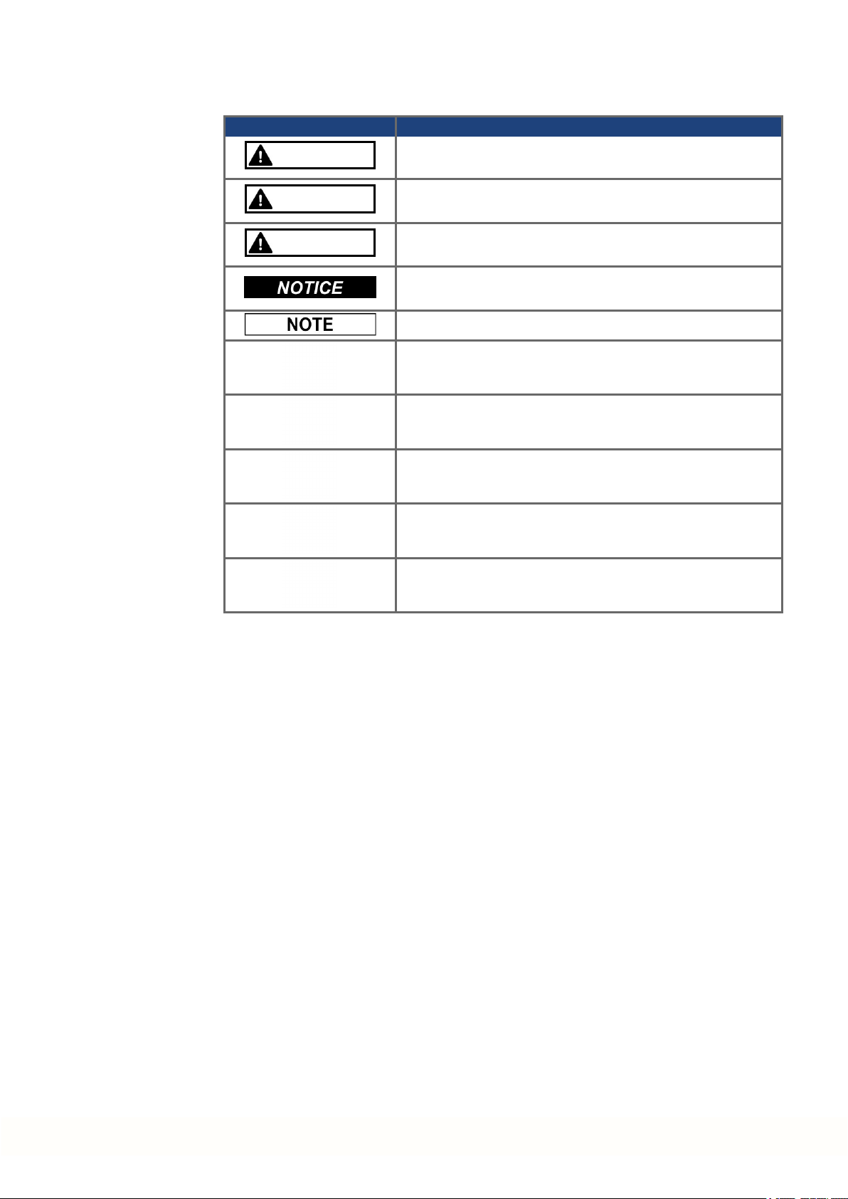
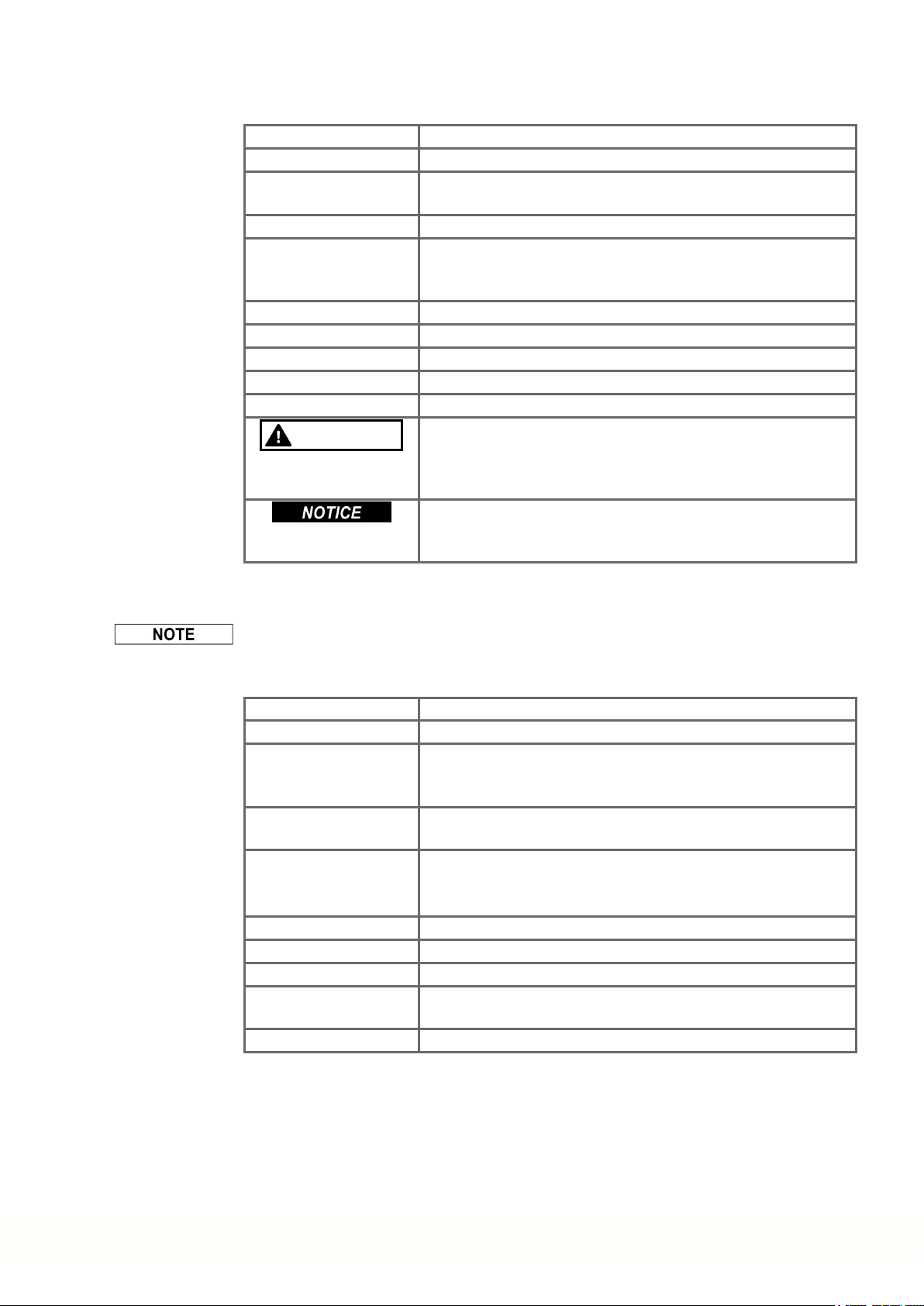
1.1.2 Symbols Used
Symbol Indication
DANGER
Indicates a hazardous situation which, if not avoided, will result in death or serious injury.
MKD Product Safety Guide | 1 English
WARNING
CAUTION
Indicates a hazardous situation which, if not avoided, could
result in death or serious injury.
Indicates a hazardous situation which, if not avoided, could
result in minor or moderate injury.
Indicates situations which, if not avoided, could result in property damage.
This symbol indicates important notes.
Warning of a danger (general). The type of danger is specified
by the text next to the symbol.
Warning of danger from electricity and its effects.
Warning of danger from hot surface.
Warning of danger from suspended loads.
Warning of danger from automatic start.
Kollmorgen | kdn.kollmorgen.com | January 2019 5
Page 6

MKD Product Safety Guide | 1 English
1.2 Product Safety
1.2.1 You should pay attention to this
Specialist staff required!
Only properly qualified personnel are permitted to perform such tasks as transport, installation and setup. Qualified specialist staff are persons with expertise in transport, installation,
assembly, commissioning and operation of electrotechnical equipment.
Transport, storage, unpacking: only by personnel with knowledge of handling electrostatically sensitive components.
Mechanical installation: only by personnel with mechanical expertise.
Electrical installation: only by personnel with expertise in electrical engineering.
Basic tests / setup: only by personnel with expertise in electrical engineering and drive
technology.
The qualifiedpersonnel must know and observe ISO 12100 / IEC 60364 / IEC 60664and
national accident prevention regulations.
Read the documentation!
Read the availabledocumentation before installation and commissioning. Improper handling
of the devices can cause harm to people or damage to property. The operator of systems
using the drive system must ensure that all personnel who work with the drive read and understand the manual before using the drive.
Check Hardware Revision!
Check the Hardware Revision Number of the product (see product label). Hardware Revsion
Number of MKD-C and MKD-N can differ from each other. This numberis the link between
your product and the manual. The product HardwareRevision Numbermust match the Hardware Revision Number on thecover page of the manual.
Pay attention to the technical data!
Adhere to the technical data and the specifications on connection conditions. If permissible
voltage values or current values are exceeded, the devices can be damaged. Unsuitable
motor or wrong wiring will damage the system components. Check the combination of drive
andmotor. Compare the rated voltage and current of the units.
Perform a risk assessment!
The manufacturerof the machine must generate a risk assessment for the machine, andtake
appropriate measures to ensure that unforeseen movements cannot cause injury or damage
to any person or property. Additional requirements on specialist staff may also result from the
risk assessment.
The manufacturershould define periodic checks of the electrical components and application.
Automatic Restart!
The drive might restart automatically after power on, voltage dip or interruption of the supply
voltage, depending on theparameter setting.
Risk of death orserious injury for humans working in the machine.
If the parameterDRV.ENDEFAULT for one MKD-N is set to 1, then place a warning sign to
the machine (Warning: Automatic Restart at Power On)and ensure, that poweron is not possible, while humans are in a dangerous zoneof the machine. In case of usingan undervoltage protection device, you must observe EN 60204-1:2006 chapter 7.5 .
6 Kollmorgen | kdn.kollmorgen.com | January 2019
Page 7

MKD Product Safety Guide | 1 English
Observe electrostatically sensitive components!
The devices contain electrostatically sensitive components which may bedamaged by incorrect handling. Electrostatically discharge your body before touching the device. Avoid contact with highly insulatingmaterials (artificial fabrics, plastic film etc.). Place the device on a
conductive surface.
Hot surface!
Drives may have hot surfaces during operation. The housing can reach temperatures above
80°C. Risk of minorburns! Measure the temperature, and wait until the housing has cooled
down below 40 °C before touching it.
Earthing!
It is vital that you ensure that the drive is safely earthed to the PE (protective earth) busbarin
the switch cabinet. Risk of electric shock. Without low-resistance earthing no personal protection can be guaranteed.
Leakage Current!
Since the leakage current to PE is more than 3.5 mA, in compliance with IEC61800-5-1 the
PE connection must either be doubledor a connecting cable with a cross-section >10 mm²
must be used. Deviating measures accordingto regional standards might be possible.
Residual current protective or monitoring devices!
MKD-C with MKD-N can cause a d.c. current in the protective earthingconductor. Wherea
residual current-operated protective (RCD) or monitoring(RCM) device is used for protection
in case of direct or indirect contact, only an RCD or RCM of Type B is allowed on the supply
side of MKD-C.
Lethal voltages!
The equipment produces highelectric voltages up to 900V. Lethal danger exists at live parts
of the device. Do not open or touch the equipment during operation. Keep theIP 54 cabinet
doors closed duringoperation. Built-in protection measures such as insulation or shielding
may not be removed. Work on the electrical installation may only be performed by trained
andqualified personnel, in compliance with the regulations for safety at work, and only with
switched off mains supply, and secured against restart.
Never undo any electrical connections to the MKD while it is live. Thereis a dangerof electrical arcing with damage to contacts and personal injury. Wait at least 5 minutes after disconnecting the product from the supply voltages (mains supply and 24V supply) before
touching potentially live sections of the equipment (such as contacts) or removing any connections.
Functional Safety
Safety functionality is not approved nor certified. Do not use this functionality in applications
with functional safety request.
Never modify the drive!
It is not allowed to modify the drive hardware without permission by the manufacturer. Opening the housingcauses loss of warranty.
Kollmorgen | kdn.kollmorgen.com | January 2019 7
Page 8
MKD Product Safety Guide | 1 English
1.2.2 Use as Directed
The MKD-C series powersupplies are exclusively intended for operatingMKD-N servo drive
modules within a cabinet and AKD-N decentralized servo drives.
The MKD-N family of servo drives is exclusively intended for driving suitable synchronous
servomotors with closed-loop control of torque, speed, and/or position.
MKD system modules arecomponents that are built into electrical plants or machines and
can only be operatedas integral components of these plants or machines. The manufacturer
of the machinemust generate a risk assessment for the machine.
When the system modules are built into machines or plant, the drive must not be used until it
has been established that the machine orplant fulfills the requirements of the regional directives.
Kollmorgen multi axes drive system
MKD must only be operated in a motion system with components from Kollmorgen. Required
additional Kollmorgencomponents are the mains chokes, hybrid string cables, hybrid motor
cables, motor power and feedback cables, servomotors.
Assembling
MKD modules must only be operated in environments suitable for the ambient conditions
defined on(➜ # 15).
Wiring
Use only Kollmorgen cables for connecting the system components.
Power supply
MKD-C must be powered from a 3 phase industrial supply network
(not more than 42 kA symmetrical rated current at 400 V and 480 V) via a mains choke 3YL.
MKD-N series drives must be powered by MKD-C intelligent power supply modules with DC
voltage from 55 VDC up to 800 VDC.
Fusing
The devices must be operatedwith fuse protection against power overload.
Motor voltage rating
The rated voltage of the motors must be at least as high as the DC bus link voltagedivided by
√2 produced by the drive (U
nMotor
>=UDC/√2).
For the cases of group installations and of DC powered drives
MKD has not been evaluated by Kollmorgen, UL, or TÜV for group installations norare ratings defined for DC input voltage.
Auxiliary voltage supply, Standby power
Standby power for the drive strings must only be used for supplying the MKD-N electronics.
24 VDC supply unit must accord to PELV (EN 60204-1) requirements.
Safe torque off
Safety functionality is not approved nor certified. Do not use this functionality in applications
with functional safety request.
8 Kollmorgen | kdn.kollmorgen.com | January 2019
Page 9
1.2.3 Prohibited Use
Otheruse thanthat described in chapter “Use as directed”is not intended and can lead to personnel injuries and equipment damage.
The system may not be used
The use of the device in the following environments is also prohibited:
Wiring the system with hybrid cables from othermanufacturers than Kollmorgen is not
allowed. Changing Kollmorgen cables or connectors is not allowed.
MKD Product Safety Guide | 1 English
with a machine that does not comply with appropriate national directives or standards,
for driving elevators,
in applications with continuous, operational short circuits to the external regen resistor
contacts.
in applications with any short circuits to the DC-Bus link contacts.
potentially explosive areas
environments with corrosive and/or electrically conductive acids, alkaline solutions, oils,
vapors, dusts
ships or offshoreapplications
1.2.4 Warning note labels
If these signs are damaged, they must be replaced immediately.
1.2.4.1 Notes placed on the product
The minimum size of the
protective earthing conductor
shall comply with the local safety
regulations for highprotectice
earthingconductor current.
Residual Voltage
Wait 5 minutes after removing
powerbefore servicing.
Kollmorgen | kdn.kollmorgen.com | January 2019 9
Page 10
MKD Product Safety Guide | 1 English
1.3 Product life cycle handling
1.3.1 Transport
Transport the MKD modules in accordance with IEC 61800-2as follows:
Transport only by qualified personnel in the manufacturer’s original recyclable packaging.
Avoid shocks while transporting.
Vibration/Shock: MKD modules are tested for environmental class 3M1 of IEC 60721-3-2.
Store at or below maximum stacking height of 8 cartons
Transport only within specified temperature ranges: -25 to +70 °C, max. rate of change 20
K/hour, class 2K3.
Transport only within specified humidity: maximum 95% relative humidity, no condensation, class 2K3.
The devices contain electrostatically sensitive components that can be damaged by incorrect handling. Electrostatically discharge yourself before touching the device. Avoid contact
with highly insulating materials, such as artificial fabrics and plastic films. Place the device
on a conductive surface.
If the packagingis damaged, check the unit for visible damage. Inform the shipper andthe
manufacturer of any damageto the package or product.
1.3.2 Packaging
1.3.3 Storage
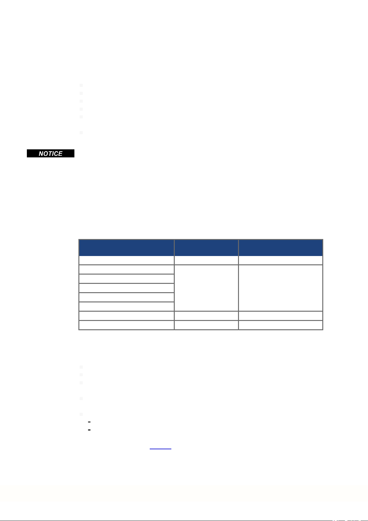
The MKD packaging consists of recyclable cardboard with inserts and a label on the outside
of the box.
Model Package Dimensions
(mm) HxWxL
MKD-C003007 580x 350 x 170 22.5
MKD-N060007
MKD-N060607
MKD-N120007
MKD-N120607
MKD-N121207
MKD-N240007 580x 350 x 110 9.5
MKD-N480007 580x 350 x 140 11.5
Store the MKD modules in accordance with IEC 61800-2as follows:
Store only in the manufacturer’s original recyclable packaging.
Store at or below maximum stacking height of 8 cartons
Store only within specified temperature ranges: -25 to +55 °C, max.rate of change20
K/hour, class 1K4.
Storage only within specified humidity: 5 to 95% relative humidity, no condensation, class
1K3.
Store the MKD in accordance with the following durationrequirements:
Less than 1 year: without restriction.
More than 1 year: capacitors in the MKD-C must be re-formed before setting upand
operating the system. Re-forming procedures are described in the Kollmorgen
Developer Network (Forming).
580x 350 x 110 8.5
Total Weight
(kg)
10 Kollmorgen | kdn.kollmorgen.com | January 2019
Page 11
1.3.4 Installation, setup and normal operation
Installation and setup information aregiven in this Guide:
Mechanical installation (➜ # 17)
Electrical installation (➜ # 18)
Setup (➜ # 19)
Normal operationtested for environmental class 3K3 according to IEC 61800-2 (➜ # 15).
The manufacturerof the machine defines the necessary end user expertise based onthe risk
assessment for the machineand describes the requirements for normal operation based on
the application.
1.3.5 Decommissioning
Only professional staff who are qualified in electrical engineering are allowedto decommission parts of the system.
DANGER: Lethal Voltages!
There is a dangerof serious personal injury or death by electrical shock or electrical arcing.
Switch off the mainswitch of the switchgearcabinet.
Securethe system against restarting.
Block the mainswitch.
Wait at least 5 minutes after disconnecting.
MKD Product Safety Guide | 1 English
1.3.6 Maintenance and cleaning
The device does not require maintenance. Opening the device voids the warranty. The inside
of the unit can only be cleaned by the manufacturer.
Do not immerse orspray the device. Avoid that liquidenters the device.
To clean the device exterior:
1. Decommission the device (see chapter 1.3.5 "Decommissioning").
2. Casing: Clean with isopropanol or similar cleaning solution.
Caution : Highly Flammable! Risk of injury by explosion and fire.
Observe the safety notes given on the cleaning liquid package.
Wait at least 30 minutes after cleaning beforeputting the device back into operation.
3. Protective grill on fan: Clean with a dry brush.
1.3.7 Disassembly
Only professional staff who are qualified in electrical engineering are allowedto disassemble
parts of the system.
1. Decommission the device (see chapter 1.3.5 "Decommissioning").
2. Check temperature.
CAUTION: High Temperature! Risk of minor burns. During operation, the heat sink of
the drive may reach temperatures above 80°C (176°F). Before touching the device,
check the temperature and wait until it has cooled below 40°C (104°F).
3. Remove the connectors. Disconnect the potential earth connection last.
4. Demount: loosen the fasteningscrews. Remove the device.
Kollmorgen | kdn.kollmorgen.com | January 2019 11
Page 12
MKD Product Safety Guide | 1 English
1.3.8 System Repair
Only professional staff who are qualified in electrical engineering are allowedto exchange
parts of the drive system.
CAUTION: Automatic Start! During replacement work a combinationof hazards and mul-
tiple episodes may occur.
Work on the electrical installation may only be performed by trained and qualifiedpersonnel, in compliance with the regulations for safety at work, and only with use of prescribed personal safety equipment.
Exchange of the device
Only the manufacturer can repair the device. Opening the device voids the warranty.
1. Decommission the device (see chapter 1.3.5 "Decommissioning").
2. Demount the device (see chapter 1.3.7 "Disassembly").
3. Send the device to the manufacturer.
4. Install a new device as described in this manual.
5. Setup the system as describedin this manual.
Exchange of other drive system parts
If parts of the drive system (forexample cables) must be replaced, proceed as follows:
1.3.9 Disposal
1. Decommission the device (see chapter 1.3.5 "Decommissioning").
2. Exchange the parts.
3. Check all connections for correct fastening.
4. Setup the system as describedin this manual.
To dispose the unit properly, contact a certified electronic scrap disposal merchant.
In accordance with the WEEE-2012/19/EC guideline and similar, the manufacturer accepts
returns of old devices and accessories for professional disposal. Transport costs are the
responsibility of the sender.
Contact Kollmorgen and clarify the logistics.
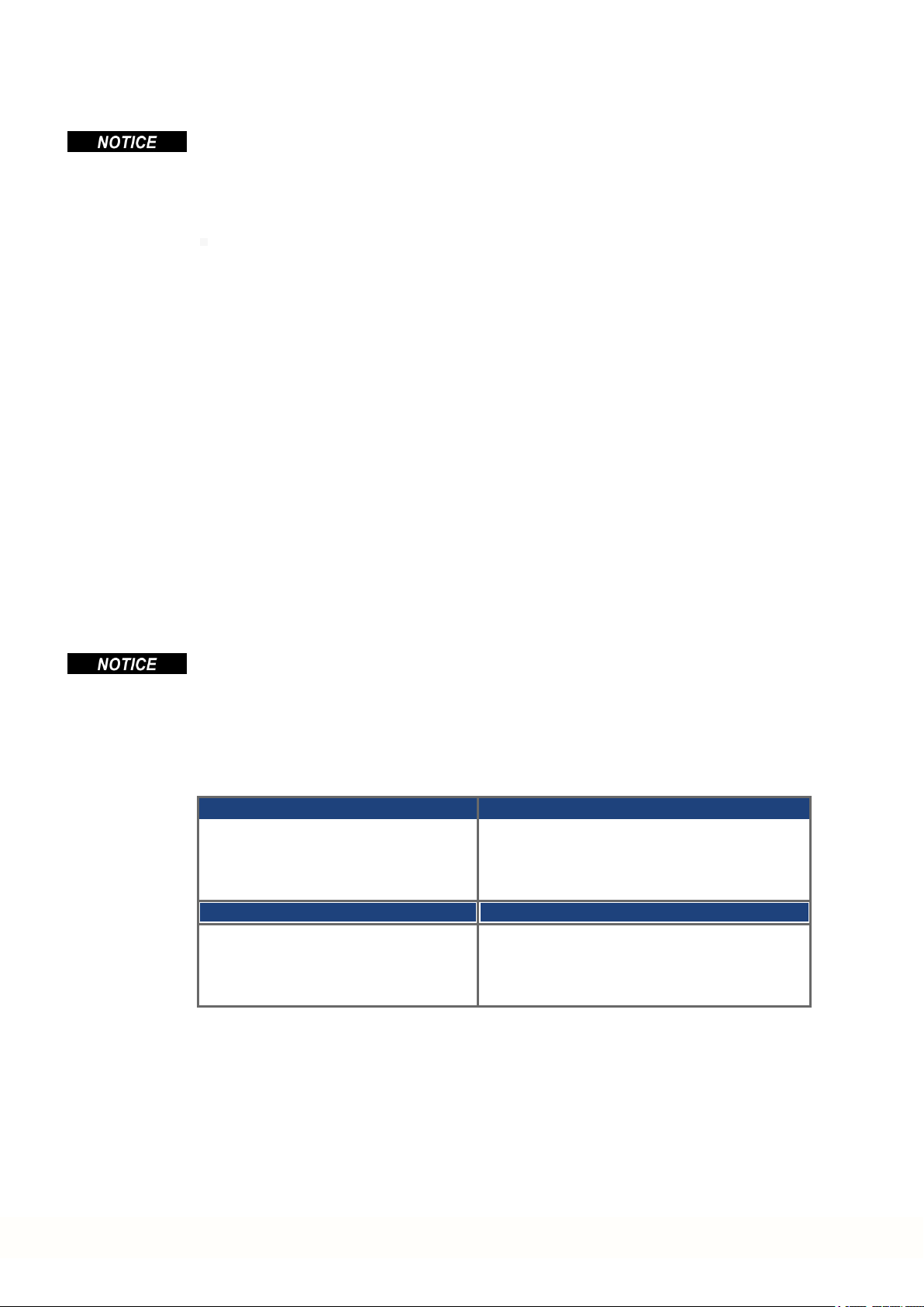
Send thedevices in the original packaging to the manufacturer address:
North America South America
KOLLMORGEN
201West Rock Road
Radford, VA 24141, USA
Europe Asia
KOLLMORGEN Europe GmbH
Pempelfurtstr. 1
40880 Ratingen, Germany
KOLLMORGEN
AvenidaJoão Paulo Ablas, 2970
Jardim da Glória, Cotia – SP
CEP 06711-250, Brazil
KOLLMORGEN
Floor 4, Building 9, No. 518,
North Fuquan Road, Changning District,
Shanghai 200335, China
12 Kollmorgen | kdn.kollmorgen.com | January 2019
Page 13
1.4 Technical description and general data
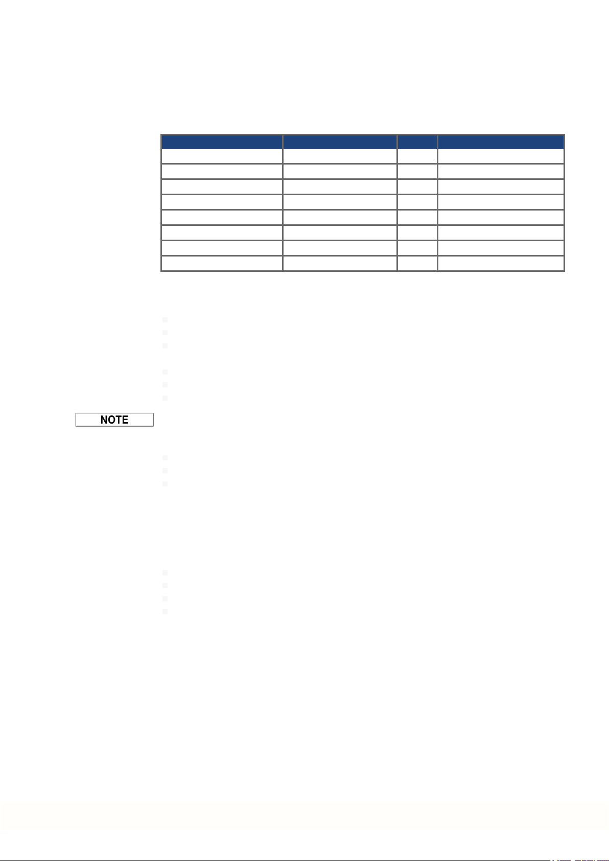
1.4.1 Package Supplied
Available MKD Modules
Variant Description Power Remarks
MKD-C003007-NAEC Central Power supply 30kW Standard
MKD-N060007-DSEC Drive Module 2.5 kW Single Axis, 6A
MKD-N060607-DSEC Drive Module 5kW Dual Axes, 2 x 6A
MKD-N120007-DSEC Drive Module 5kW Single Axis, 12A
MKD-N120607-DSEC Drive Module 7.5 kW Dual Axes, 12A + 6A
MKD-N121207-DSEC Drive Module 10 kW Dual Axes, 2 x 12A
MKD-N240007-DSEC Drive Module 10 kW SingleAxis, 24A
MKD-N480007-DSEC Drive Module 20 kW SingleAxis, 48A
When a MKD module is ordered, the following items are included in the package:
MKD-C package:
The ordered module itself
Printedcopy of MKD Product Safety Guide
DVD containing the setup software, WorkBench, and all product documentation in digital
format.
Mating connectors MKD-C: X12, X13, X14, X15, X16, X25
OneMKD-N DC-Bus link cover
Two connector covers M23 for AKD-N
MKD Product Safety Guide | 1 English
The M23 connector covers are required forprotecting X2 of the last AKD-N in the strings.
MKD-N package:
The ordered module itself
Data Sheet
Mating connectors MKD-N: X9, X24, X26
Accessories:
Accessories must be ordered separately if required.
Accessories for AKD-N see regional Accessories Manual or AKD-N Installation Manual.
Spare parts
Connector Kit MKD-C-Conkit (X12, X13, X14, X15, X16, X25)
Connector Kit MKD-N-Conkit 6 to 12 A single (X9, X24, X26, X29A)
Connector Kit MKD-N-Conkit 6 to 12 A double (X9, X24, X26, X29A, X29B)
Connector Kit MKD-N-Conkit 24 to 48 A (X9, X24, X26, X29A, X30A)
Kollmorgen | kdn.kollmorgen.com | January 2019 13
Page 14
MKD Product Safety Guide | 1 English
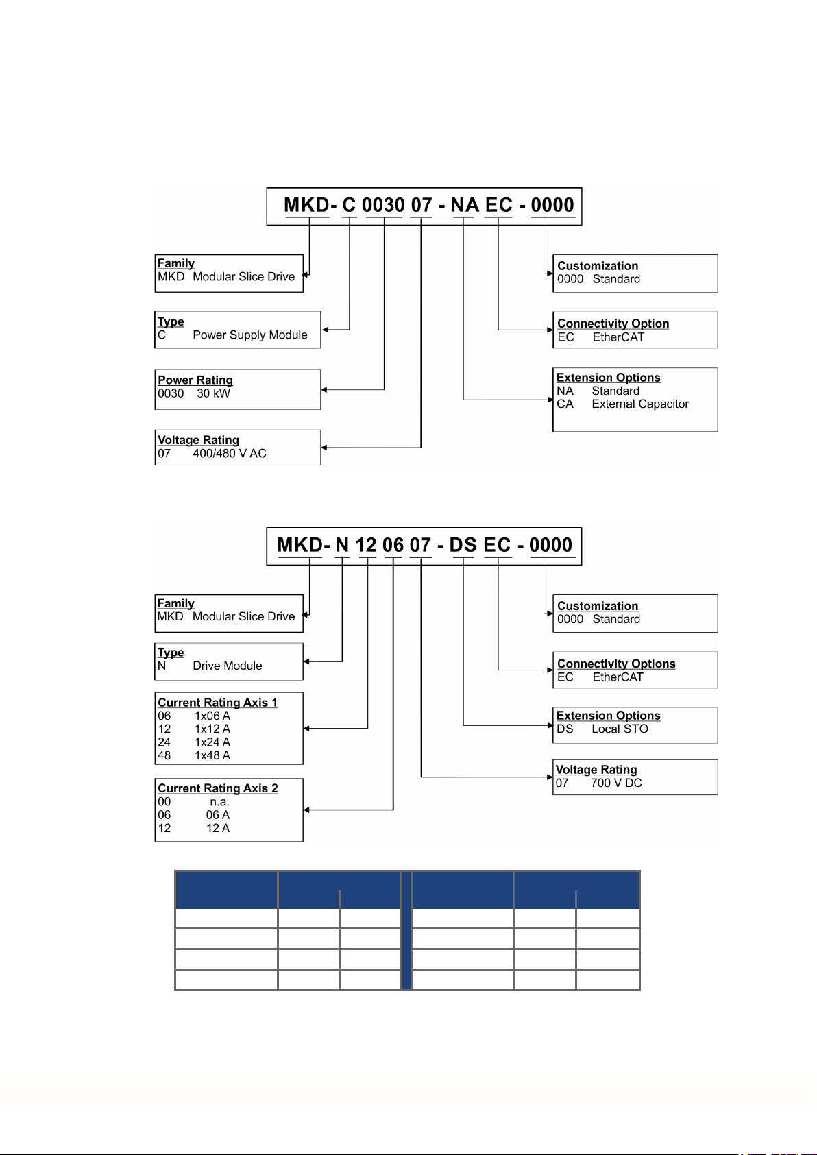
1.4.2 Part Number Scheme
Use the part numberscheme for product identification only, not for the order process,
because not all combinations of features arepossible, always.
1.4.2.1 MKD-C modules
Customization code codingfor customerspecials (not relevant for functional safety).
1.4.2.2 MKD-N modules
Available drive modules:
Current rating Current rating
Single Axis Axis 1 Axis 2 Dual Axes Axis 1 Axis 2
MKD-N0600 06 A - MKD-N0606 06 A 06 A
MKD-N1200 12 A - MKD-N1206 12 A 06 A
MKD-N2400 24 A - MKD-N1212 12 A 12 A
MKD-N4800 48 A -
Customization code codingfor customerspecials (not relevant for functional safety).
14 Kollmorgen | kdn.kollmorgen.com | January 2019
Page 15
1.4.3 Ambient Conditions in normal operation
Storage, Transport (➜ # 10)
Normal operation Environmental class 3K3 accordingto IEC 61800-2
Surrounding air tem-
perature in operation
Humidity in operation Relative humidity 5 to 85%, nocondensation, class 3K3
Site altitude Up to 1000 meters above mean sealevel without restriction
Pollution level Pollution level 2 as per IEC 60664-1
Vibrations Class 3M1 according to IEC 60721-3-3
Environmental area Cabinet IP 54 according to IEC 60529
Mounting position Vertical
Ventilation Built-in fan.
CAUTION
0 to +40 °C under rated conditions
+40 to +55 °C with continuous current derating4 % perKelvin
1,000 to max. 2,000 meters above mean sea level with power
derating1.5%/100 m
Continuous noise up to 60dBA during operation. Keep cabinet
doors closed duringoperation. To reduce inconvenience, we suggest to use ear protection if cabinet doors must be opened during
normal operation.
The device shuts down in case of excessively high temperature
in the control cabinet. Make sure sufficient forcedventilationis
supplied within the control cabinet.
MKD Product Safety Guide | 1 English
1.4.4 Electrical Data
Electrical data (➜ # 53)
1.4.5 System limits
Length String 2/3 Maximum 100 m total cable length perstring.
Number of MKD-C Limitedby fieldbus protocol.
Number of MKD-N
axes
Number of AKD-N Maximum 14per string, total maximum 28 onstrings 2 and3,
Output current Use coincidence factor of the axes for distribution and system
Total power At 565 V to 680 V limited to 30kW.
String 2/3 power At 565 V to 680 V limited to 10kW for each string.
String standby power At 55 V limited to 180W for each string.
Motor Brake power You can control up to 3 motorbrakes per string. Available power
Service Interface X18 Ethernet TCP/IP, 100 Mbit/s, max. cable distance 100m
Maximum 14axes for string 1, total maximum 28 axes if string 1
and2 are combined (observe total power and current restrictions).
(observe total power and current restrictions).
poweroptimization.
String 1: 43 A, String 2: 16 A, String 3: 16 A
for brakes is 76 W per string(= 3.2 A @ 24 VDC).
Kollmorgen | kdn.kollmorgen.com | January 2019 15
Page 16
MKD Product Safety Guide | 1 English
1.5 Safe Torque Off (STO)
Safety functionality is not approved nor certified. Do not use this functionality in applications
with functional safety request.
Refer to the MKD Installation Manual for full information on functional safety.
The safety properties given by Kollmorgenlisted in the appendix (➜ # 77) can be reached if
the Kollmorgen components are used. The resulting Functional Safety classification (SIL
and/or PL level)must be calculatedacross the drive system.
MKD-C connector X16:
global STO (String 2/3) inputs of the system powered by this MKD-C.
MKD-N connector X26:
local STO (axis 1 and axis 2 if built-in) input of the drive module.
AKD-N connectors X6:
local STO input of the AKD-N-DS/DT drive modules.
Global STO
There is one STO input for every DC Power string. The string STO input release the power
output stageof all AKD-N (without option DS/DT) connected to the string as longas a 24 V
signal is applied to this input.
Local STO
The local STO input releases the power output stage of the MKD-N drive axis as longas a 24
V signal is applied to this input.
16 Kollmorgen | kdn.kollmorgen.com | January 2019
Page 17
1.6 Mechanical Installation
Dimensions and mounting hints see (➜ # 55)and refer to the MKD Installation Manual.
1.6.1 Important Notes
MKD-C and MKD-N devices must be mountedin cabinets only with protection class IP 54
according to IEC 60529.
MKD Product Safety Guide | 1 English
CAUTION
Risk of electrical shock, if the servo amplifier (or the motor) is not properly EMC-grounded.
Do not use painted (i.e. non-conductive) mounting plates.
In unfavourable circumstances, use copper mesh tape between the earthing bolts and
earth potential to deflect currents.
Protect the device from impermissible stresses. In particular, do not let any components
become bent or any insulation distances altered during transport and handling. Avoid contact with electronic components and contacts.
The modules will switch itself off in case of overheating. Ensure that the mountingspace
matches the requirements (➜ # 15).
Do not mount devices that produce magnetic fields directly beside the device. Strong magnetic fields can directly affect internal components. Install devices which produce magnetic
field with distance to the MKD-C and/orshield themagnetic fields.
1.6.2 Guide to Mechanical Installation
For details refer to the MKD Installation Manual.The following tools are required (at a min-
imum) to install the MKD-C and MKD-N modules; yourspecific installationmay require additional tools.
M4 hexagon socket-cap screws (ISO 4762)
3 mm T-handle Allen key
No. 2 Phillips head screwdriver
Small slotted screwdriver
High EMC Voltage Level!
Install the modules as follows:
1. Prepare the site. The MKD modules must be mounted in a closed control cabinet (➜ #
15). The site must be free from conductive or corrosive materials.
2. Check that the ventilation of the modules is unimpeded, and keepwithin the permitted
ambient temperature (➜ # 15). Keep the required space clearance above andbelow the
modules (➜ # 56).
3. If cooling systems are used forthe control cabinet, position the cooling system so that
condensation water cannot drip onto the modules or peripheral devices.
4. Assemble the power supply module and the drive modules on the conductive, grounded
mounting plate in the cabinet.
5. Ground the modules, the mounting plate, motor housing, GND of 24V supply and CNCGND of the control system.
For mechanical installation of AKD-N to the machine, refer to the AKD-N Installation
Manual.
Kollmorgen | kdn.kollmorgen.com | January 2019 17
Page 18

MKD Product Safety Guide | 1 English
1.7 Electrical Installation
Connectors and Wiring overview see (➜ # 57)and refer to the MKD Installation Manual.
1.7.1 Important Notes
Only professional staff who are qualified in electrical engineering are allowedto install the
drive system. Wires with colorgreen with one or more yellow stripes must not be used other
than for protective earth (PE) wiring.
DANGER
There is a dangerof serious personal injury or death by electrical shock or electrical arcing.
Capacitors can still have dangerous voltages present up to 5 minutes after switchingoff the
supply power. Control and power connections can still be live, even if the motor is not rotating.
Only install and wire the equipment when it is not live.
Make sure that the cabinet is safely disconnected (forinstance, with a lock-out and warning signs).
Never remove electrical connections to the drive while it is live.
Wait at least 5 minutes after disconnecting the drive from the main supply power before
touching potentially live sections of the equipment (e.g. contacts) or undoingany connections.
To be sure, measure the voltage in the DC bus link and wait until it has fallen below 50 V.
Since the leakage current to PE is more than 3.5 mA, in compliance with IEC61800-5-1 the
PE connection must either be doubledor a connecting cable with a cross-section >10 mm²
must be used. Deviating measures accordingto regional standards might be possible.
WrongDC Bus link voltage, unsuitable motoror wrong wiringwill damage the system components. Check the combination of drive and motor. Compare the rated voltage and current
of the units. Implement the wiring according to the connection diagrams: (➜ # 57).
It is permissible to use the setup software to alter the settings of the device. Any other alterations will invalidate the warranty.
High Voltage up to 900 V!
1.7.2 Guide to electrical installation
For details refer to the MKD Installation Manual. Install the drive electrical system as follows:
1. Select cables accordance with the planned system topology, see (➜ # 15).
2. Observe the maximum cable length definition (➜ # 15).
3. Install shielding and ground the system components, see (➜ # 61).
4. Wire the system components.
- Observe "Recommendations for EMI noise reduction": see MKD Installation Manual
- Connect all interface according to the wiring diagrams in the MKD Installation Manual.
5. Check the wiring against the wiringdiagrams in the MKD Installation Manual.
For electrical installation of AKD-N to the machine, referto the AKD-N Installation Manual.
18 Kollmorgen | kdn.kollmorgen.com | January 2019
Page 19
1.8 Setup
For detailed information on functional safety refer to the MKD Installation Manual.
Programming parameters and control loop behavior: see WorkBench online help.
The fieldbus setup is describedin the corresponding manual on the DVD.
1.8.1 Important Notes
Beforetesting andsetup, the manufacturer of the machine must generate a risk assessment
for the machine and take appropriate measures so that unforeseen movements cannot
cause injury or damage to any person or property.
Only professional personnel with extensive knowledge in the fields of electrical engineering
anddrive technology are allowed to test and set up the drive.
MKD Product Safety Guide | 1 English
DANGER
There is a dangerof serious personal injury or death by electrical shock. Lethal danger exists
at live parts of the device.
Built-in protection measures such as insulation orshielding may not be removed.
Work on the electrical installation may only be performed by trained and qualifiedpersonnel, in compliance with the regulations for safety at work, and only with switched off
mains supply, and secured against restart.
WARNING
Risk of death orserious injury for humans working in the machine. The drive might restart
automatically after power on, voltage dip or interruption of the supply voltage, depending on
the parameter setting. If parameterDRV.ENDEFAULT is set to 1,
then place a warning sign ("WARNING: Possible Automatic Restart" or similar) to the
machine.
Ensure, that power on is not possible, while humans are in a dangerous zone of the
machine.
CAUTION
Risk of minor burns. The heat sink of the drive can reach temperatures up to 80°C in operation.
Check the heat sink temperaturebefore handlingthe drive.
Wait until the heat sink has cooled down to 40°C before touching it.
Lethal Voltage!
Automatic Restart!
High Temperature!
If a device has been stored for more than 1 year, you must re-form the capacitors in the DC
bus link circuit. Re-forming procedures aredescribed in the KollmorgenDeveloper Network
(Forming).
Kollmorgen | kdn.kollmorgen.com | January 2019 19
Page 20

MKD Product Safety Guide | 1 English
1.8.2 Initial System Test
1. Unpack the devices and accessories. Observe the safety instructions in the documentation.
2. Mount the devices and wire the system.
3. Validate mechanical and electrical installation.
4. Validate IP addresses
5. Make sure you have on hand the following information about the drive components:
rated mains supply voltage
motor type (motor data, if the motor type is not listed in the motordatabase)
feedback unit built into the motor (type, poles/lines/protocol)
moment of inertia of the load
1.8.2.1 Set system addresses
The MKD-C IP address can beset with the rotary switch. When connecting the MKD-C directly to a PC, static IP addressing (not 0) is recommended.
Example: if S1 is set to 5 – the IP address is 192.168.0.5
WorkBench looks for IP address in the subnet to detect devices in the LAN and start communication. Refer to the WorkBench Online Help for information.
1.8.2.2 Confirm connections
Switch on 24 VDC logic power for the system (mains supply voltage is not neededfor communications).
Confirm that the greenlink LED 1 on the MKD-C and on the PC are both illuminated.
While the PC is connecting, yourstatus bar will show the following acquiring icon:
Wait for this icon to changeto the limited functionality icon (this process can take up to one
minute).
Although Windows displays this limited functionality icon for the drive connection, the PC
can communicate fully with the drive. Using WorkBench, you can now configure the drive
throughthis connection.
1.8.2.3 Install and start WorkBench
WorkBench is available from the DVD included with the drive and on theKollmorgen Website: www.kollmorgen.com. Select the install file and follow the instructions given by the
installer.
Once installation is complete, click the WorkBench icon to start the program.
1.8.2.4 Parameterize and enable the axes in WorkBench
Refer to the WorkBench Online Help for information.
20 Kollmorgen | kdn.kollmorgen.com | January 2019
Page 21

1.9 Troubleshooting the MKD System
Drive problems occur for a variety of reasons, depending on the conditions in yourapplication. The causes of faults in multi-axis systems can be very complex. If you cannot resolve
a fault, Kollmorgen customersupport can give you furtherassistance.
Eliminate errors and faults in compliance with work safety rules. Troubleshooting only by
qualified and trained staff.
Details on the removal of faults can be found in the WorkBench onlinehelp.
MKD Product Safety Guide | 1 English
Kollmorgen | kdn.kollmorgen.com | January 2019 21
Page 22

MKD Product Safety Guide | 1 English
---/ ---
22 Kollmorgen | kdn.kollmorgen.com | January 2019
Page 23

MKD Product Safety Guide | 2 Deutsch
2 Deutsch
2.1 Allgemeines 24
2.1.1 Hinweise für die gedruckte Ausgabe(Papierversion) 24
2.1.2 Verwendete Symbole 25
2.2 Produktsicherheit 26
2.2.1 Das sollten Sie beachten 26
2.2.2 Bestimmungsgemäße Verwendung 28
2.2.3 Nicht bestimmungsgemäße Verwendung 29
2.2.4 Warnaufkleber 29
2.3 Produkt Lebenszyklus, Handhabung 30
2.3.1 Transport 30
2.3.2 Verpackung 30
2.3.3 Lagerung 30
2.3.4 Installation, Setup und Normalbetrieb 31
2.3.5 Außer Betrieb nehmen 31
2.3.6 Wartung und Reinigung 31
2.3.7 Demontage 31
2.3.8 System Reparatur 32
2.3.9 Entsorgung 32
2.4 Technische Beschreibung und allgemeine Daten 33
2.4.1 Lieferumfang 33
2.4.2 Typenschlüssel 34
2.4.3 Umgebungsbedingungen im normalen Betrieb 35
2.4.4 Elektrische Daten 35
2.4.5 Systemgrenzen 35
2.5 Safe Torque Off (STO) 36
2.6 Mechanische Installation 37
2.6.1 Wichtige Hinweise 37
2.6.2 Anleitung für die mechanische Installation 37
2.7 Elektrische Installation 38
2.7.1 Wichtige Hinweise 38
2.7.2 Anleitung für die elektrische Installation 38
2.8 Setup 39
2.8.1 Wichtige Hinweise 39
2.8.2 Basis Systemtest 40
2.9 Fehlerbehebung beim MKD System 41
Kollmorgen | kdn.kollmorgen.com | January 2019 23
Page 24
MKD Product Safety Guide | 2 Deutsch
2.1 Allgemeines
Der MKD-C/N Product Safety Guide liefert die relevanten Informationen für sichere Instal-
lation und Inbetriebnahme der MKD Systemmodule MKD-C Netzteil und MKD-N Servoverstärker.
Vollständige Informationen finden Sie im MKD-C/N InstallationManual , in derAKD-N
Betriebsanleitung und weiteren Kollmorgen Dokumenten.
Weitere Dokumente auf der beiliegenden DVD:
WorkBenchOnlinehilfe: Beschreibt die VerwendungdesSystems in gängigenApplikationen. Sie liefert auch Hinweise für die Optimierung der Systemleistung. Die Online
Hilfe beinhaltet den Parameter and Command Reference Guide mit Informationenzu Para-
metern und Befehlen, die zum Programmieren des Systems benutzt werden.
EtherCAT Communication: beschreibt die Verwendung des Systems in EtherCAT Applikationen.
Diese Dokumente finden Sie auf der DVD in der Verpackungdes Servoverstärkers. Alle
Dokumente können Sie von der Kollmorgen Website www.kollmorgen.com herunterladen.
2.1.1 Hinweise für die gedruckte Ausgabe (Papierversion)
Jedem Produkt liegt eine gedruckte Ausgabe dieses Handbuchs
bei. Aus ökologischen Gründen wurde das Dokument verkleinert
auf DIN A5 gedruckt.
Sollten Sie Schwierigkeiten haben, die Schriftgröße des verkleinert gedruckten Exemplars zu lesen, können Sie die PDF Version im DIN A4 Format 1:1 ausdrucken und verwenden. Sie finden
die PDF Version auf der dem Produkt beiliegenden DVD und auf
der Kollmorgen Internetseite.
24 Kollmorgen | kdn.kollmorgen.com | January 2019
Page 25

2.1.2 Verwendete Symbole
Symbol Bedeutung
GEFAHR
WARNUNG
MKD Product Safety Guide | 2 Deutsch
Weist auf eine gefährliche Situation hin, die, wenn sie nicht vermieden wird, zum Todeoder zu schweren, irreversiblenVerletzungen führenwird.
Weist auf eine gefährliche Situation hin, die, wenn sie nicht vermieden wird, zum Todeoder zu schweren, irreversiblenVerletzungen führenkann.
VORSICHT
Weist auf eine gefährliche Situation hin, die, wenn sie nicht vermieden wird, zu leichten Verletzungen führen kann.
Dieses Symbol weist auf eine Situation hin, die, wenn sie nicht
vermieden wird, zu Beschädigung von Sachen führenkann.
Dieses Symbol weist auf wichtige Informationen hin.
Warnungvor einer Gefahr(allgemein). Die Art der Gefahr wird
durch dennebenstehenden Warntext spezifiziert.
Warnungvor gefährlicher elektrischer Spannungund derenWirkung.
Warnungvor Gefahr durch heiße Oberfläche.
Warnungvor Gefahr durch hängende Last.
Warnungvor Gefahr durch automatischem Anlauf.
Kollmorgen | kdn.kollmorgen.com | January 2019 25
Page 26

MKD Product Safety Guide | 2 Deutsch
2.2 Produktsicherheit
2.2.1 Das sollten Sie beachten
Fachpersonal erforderlich
Für Arbeitenwie Transport, Installation, Inbetriebnahme und Instandhaltung darf nur qualifiziertes Personal eingesetzt werden. Qualifiziertes Personal sind Personen, die mit Transport, Installation, Inbetriebnahme und Betrieb von elektrischen Antrieben vertraut sind.
Transport, Lagerung, Auspacken: nur durch Personal mit Kenntnissen in der Behandlung
elektrostatisch gefährdeter Bauelemente.
Mechanische Installation: nur durch Personal mit Kenntnissen in mechanischen Arbeiten.
Elektrische Installation: nur durch Personal mit Kenntnissen in elektrotechnischenArbeiten.
Inbetriebnahme: nur durch Fachleute mit weitreichendenKenntnissen in den Bereichen
Elektrotechnik und Antriebstechnik.
Das Fachpersonal muss ebenfalls ISO 12100 / IEC 60364 / IEC 60664 und nationale Unfallverhütungsvorschriften kennen undbeachten.
Dokumentation lesen
Lesen Sie vor derMontage und Inbetriebnahmedie vorliegende Dokumentation. Falsches
Handhaben der Geräte kann zu Personen- oder Sachschäden führen. Der Betreiber muss
dahersicherstellen, dass alle mit Arbeiten am Antriebssystem betrauten Personen das Handbuch gelesenund verstanden haben und dass die Sicherheitshinweise in diesem Handbuch
beachtet werden.
Hardware Revision prüfen
PrüfenSie die Hardware-Revisionsnummer des Produkts (siehe Typenschild). Hardware
Revisionsnummer von MKD-C und MKD-N können voneinander abweichen. Die Nummer ist
die Verknüpfung zwischen dem Produkt und dem Handbuch. Diese Revisionsnummer muss
mit der Hardware-Revisionsnummerauf der Betriebsanleitungübereinstimmen.
Technische Daten beachten
Halten Sie die technischen Daten und die Angaben zu den Anschlussbedingungen ein. Wenn
zulässige Spannungswerte oder Stromwerte überschritten werden, können die Geräte
geschädigt werden. Ein ungeeigneter Motor oder fehlerhafte Verdrahtung beschädigen die
Systemkomponenten. Prüfen Sie die Kombination aus Verstärker und Motor. Gleichen Sie
die Nennspannung und den Nennstrom der Komponentenab.
Risikobeurteilung erstellen
Der Hersteller der Maschine muss eine Risikobeurteilung für die Maschine erstellen und
geeignete Maßnahmentreffen, dass unvorhergesehene Bewegungennicht zu Verletzungen
oder Sachschädenführen können. Aus der Risikobeurteilung leiten sich eventuell auch
zusätzliche Anforderungen an das Fachpersonal ab.
Der Hersteller der Maschine muss regelmäßige Überprüfungen der elektrischen Komponenten und Applikationenfestlegen.
Automatischer Wiederanlauf!
Der Antriebkannabhängig von der Parametereinstellung nach dem Einschalten derNetzspannung, bei Spannungseinbrüchen oder Unterbrechungenautomatisch anlaufen.
Es besteht die Gefahr von tödlichen oder schweren Verletzungen für Personen, die in der
Maschine arbeiten.
Wenn der Parameter DRV.ENDEFAULT eines MKD-N auf 1 gesetzt ist, warnen Sie an der
Maschine mit einem Warnschild (Warnung: Automatischer Wiederanlauf nach Einschalten!)
undstellen Sie sicher, dass ein Einschalten der Netzspannung nicht möglich ist, während
sich Personen im gefährdeten Bereich der Maschineaufhalten. WennSie einen Unterspannungsschutz benutzen, beachten Sie Kapitel 7.5 der EN 60204-1:2006.
26 Kollmorgen | kdn.kollmorgen.com | January 2019
Page 27

MKD Product Safety Guide | 2 Deutsch
Elektrostatisch empfindliche Bauteile
Die Geräte enthalten elektrostatisch gefährdete Komponenten, die durch unsachgemäßen
Gebrauch beschädigt werdenkönnen. Entladen Sie Ihren Körper elektrostatisch, bevor Sie
das Gerät berühren. Vermeiden Sie es, hoch isolierendeStoffe zu berühren (Kunstfasern,
Plastikfolie usw.). Legen Sie das Gerät auf eineleitfähige Oberfläche.
Heiße Oberfläche
Die Oberflächenvon Verstärkernkönnen im Betrieb sehr heiß werden. Das Gehäuse kann
Temperaturen über80 °C erreichen. Gefahr leichter Verbrennungen. Messen Sie die Temperatur. Warten Sie, bis das Gehäuse auf unter 40 °C abgekühlt ist, bevor Sie es berühren.
Erdung
Stellen Sie die ordnungsgemäßeErdungdes Gerätes mit derPE-Schiene im Schaltschrank
als Bezugspotential sicher. Gefahr durch elektrischen Schlag.
Ohne niederohmigeErdungist keinepersonelle Sicherheit gewährleistet
Ableitstrom
Da der Ableitstrom zu PE mehr als 3,5 mA beträgt, muss in Übereinstimmungmit der Norm
EN61800-5-1 derPE-Anschluss entweder doppelt ausgeführt oder ein Anschlusskabel mit
einem Querschnitt von >10 mm² verwendet werden. Abweichende Maßnahmen sindin Übereinstimmung mit regionalen Vorschriften möglich.
Fehlerstrom Schutzschalter oder Überwachungsgeräte!
MKD-C mit MKD-N kanneinen Gleichstrom im Schutzerder erzeugen. Wo für denSchutz im
Falle einerdirekten oder indirekten Berührung eineFehlerstrom-Schutzeinrichtung (RCD)
oder ein Fehlerstrom-Überwachungsgerät (RCM) verwendet wird, ist auf der Stromversorgungsseite des MKD-C nur einRCD oder RCM vom Typ B zulässig.
Tödliche Spannung!
Die Geräte erzeugen hohe elektrische Spannungen bis zu 900 V. Lebensgefahrbeim Berührenvon spannungsführenden Teilen. Öffnen oder berühren Sie die Geräte während des
Betriebs nicht. Halten Sie während des Betriebs alle Türen des IP54 Schaltschranks
geschlossen. Eingebaute Schutzmaßnahmenwie Isolation oder Schirmung dürfen nicht entfernt werden. Arbeiten an der elektrischen Installation sollen nur von geschultem und qualifizierten Personal unter Beachtungder Arbeitssicherheitsbestimmungen bei abgeschalteter
undgegenWiedereinschalten gesicherter Netzspannungdurchgeführt werden.
Trennen Sie nie die elektrischen Verbindungen zum MKD, während dieserSpannung führt.
Es besteht die Gefahr von Lichtbogenbildung mit Verletzungsgefahr (Verbrennungen oder
Erblindung)und Schäden anKontakten. Warten Sie nach dem Trennen des Gerätes von den
Versorgungsspannungen(Netzversorgung und 24V Versorgung)mindestens 5 Minuten,
bevor Sie Geräteteile, die potenziell Spannung führen (z. B. Kontakte), berührenoder
Anschlüsse trennen.
Funktionale Sicherheit
Die Safety Funktionensind nicht freigegeben undnicht zertifiziert. Benutzen Sie diese Funktion nicht in Applikation, die funktionale Sicherheit erfordern.
Geräte nicht verändern
Veränderungan der Servoverstärker Hardware ohne Erlaubnis des Herstellers sind nicht
zulässig. Öffnen derGeräte bedeutet Verlust der Gewährleistung.
Kollmorgen | kdn.kollmorgen.com | January 2019 27
Page 28

MKD Product Safety Guide | 2 Deutsch
2.2.2 Bestimmungsgemäße Verwendung
MKD-C Netzteile sind ausschließlich für den Betriebvon MKD-N Servoverstärker Modulen
imSchaltschrank und AKD-N dezentralen Servoverstärkerngeeignet.
Die MKD-N Servoverstärkersind ist ausschließlich zum Antrieb von geeigneten SynchronServomotoren mit geschlossenem Drehmoment-, Drehzahl- und/oder Positionsregelkreis vorgesehen.
MKD Systemmodule sind Komponenten, die in elektrische Anlagen oder Maschinen eingebaut werdenund nurals integrierte Bestandteile dieser Anlagen oder Maschinen betrieben
werden können. Der Hersteller der Maschine muss eine Risikoanalyse der Maschine erstellen.
Wenn dieSystemmodule in Maschinen oder Anlagen eingebaut werden, darf derAntrieb
nicht verwendet werden, bis sichergestellt wurde, dass die Maschine oder Anlage die regionalen Richtlinien erfüllt.
Kollmorgen Multi-Achsen Antriebssystem
MKD darf nur in Antriebssystemen mit Komponenten von Kollmorgen eingesetzt werden.
Zusätzlich benötigte Kollmorgen Komponentensind die Netzdrossel, Hybrid Strangkabel,
Hybrid Motorkabel, Motorleistungskabel und Motorfeedbackkabel sowie Servomotoren.
Montage
MKD Module dürfen nurin geschlossenen Schaltschränken betrieben werden, die sich für die
definiertenUmgebungsbedingungen eignen(➜ # 35).
Verdrahtung
Verwenden Sie nurKollmorgen Leitungen zur Verbindung der Systemkomponenten.
Spannungsversorgung
MKD-C muss an einem 3 phasigen, industriellen Versorgungsnetz betrieben werden
(maximaler symmetrischerNennstrom bei 400 V und 480 V: 42 kA) übereine Netzdrossel
3YL.
MKD-N Servoverstärkermüssen von den intelligenten MKD-C Netzteilen mit einerGleichspannung von 55VDC bis 800 VDC versorgt werden.
Sicherungen
Die Geräte müssen mit einerAbsicherung gegen Überlast betrieben werden.
Motor-Nennspannung
Die Nennspannung der Motoren muss mindestens so hoch sein wie die vom Verstärker
erzeugte DC-Zwischenkreisspannung geteilt durch √2 (U
nMotor
>=UDC/√2).
Gruppeninstallationen und mit Gleichstrom versorgte Antriebe
Der MKD wurde weder von Kollmorgen, UL noch dem TÜV für Gruppeninstallation untersucht. Es sind keine Werte für eineDC Spannungsversorgung definiert.
Hilfsspannungsversorgung, Standby Versorgung
Die Standby Versorgung fürdie Antriebsstränge darf nur für die Versorgung der MKD-N Elektronik verwendet werden. Das 24 VDC Netzteil muss die Anforderungen von PELV (EN
60204-1) erfüllen.
Safe Torque Off
Die Safety Funktionensind nicht freigegeben undnicht zertifiziert. Benutzen Sie diese Funktion nicht in Applikation, die funktionale Sicherheit erfordern.
28 Kollmorgen | kdn.kollmorgen.com | January 2019
Page 29

2.2.3 Nicht bestimmungsgemäße Verwendung
Eine andere Verwendung als in Kapitel "Bestimmungsgemäße Verwendung" beschrieben ist
nicht bestimmungsgemäß und kann zu Schäden bei Personen, Gerät oder Sachen führen.
Das System soll nicht verwendet werden
in Maschinen, die nicht den geltenden nationalen Richtlinien oder Normen entsprechen,
zum Antrieb von Aufzügen,
in Anwendungen mit häufigen, betriebsmäßigen Kurzschlüssen der Anschlüsse des
Bremswiderstandes,
in Anwendungen mit Kurzschlüssen der DC+/DC- Zwischenkreisanschlüsse.
Die Verwendung des Gerätes in den folgenden Umgebungen ist ebenfalls untersagt:
explosionsgefährdete Bereiche,
Umgebungenkorrosiven und/oder elektrisch leitenden Säuren, alkalischen Lösungen,
Ölen, Dämpfen und Staub,
Schiffe oder Offshore-Anwendungen.
Verdrahtung des Systems mit Hybridkabeln anderer Hersteller als Kollmorgen ist nicht
erlaubt. Verändern von Kollmorgen Kabeln oderSteckern ist nicht erlaubt.
MKD Product Safety Guide | 2 Deutsch
2.2.4 Warnaufkleber
Beschädigte Warnsymbole müssen sofort ersetzt werden.
2.2.4.1 Hinweise auf dem Produkt
The minimum size of the
protective earthing conductor
shall comply with the local safety
regulations for highprotectice
earthingconductor current.
Übersetzung:
Die Mindestgröße der Schutzerdungsleiter
soll den örtlichen Sicherheitsvorschriften für
hohen Schutzerdungsstrom entsprechen.
Residual Voltage
Wait 5 minutes after removing
powerbefore servicing.
Übersetzung:
Restspannung
5 Minuten nach
.
Abschalten der Leistung
bis zur Wartung warten.
Kollmorgen | kdn.kollmorgen.com | January 2019 29
Page 30

MKD Product Safety Guide | 2 Deutsch
2.3 Produkt Lebenszyklus, Handhabung
2.3.1 Transport
Transportieren Sie die MKD Module gemäß EN 61800-2 wie folgt:
Transport nur durch qualifiziertes Personal in der wiederverwertbaren Originalverpackung
des Herstellers.
Beim Transport Stöße vermeiden.
Vibration/Schock: MKD Module sind geprüft für Klasse 3M1 gemäß IEC 60721-3-2.
Höchstens mit der maximalen Stapelhöhe (8Kartons) stapeln.
Nur innerhalb der angegebenen Temperaturbereichetransportieren: -25bis +70°C, max.
Änderungsrate 20 K/Stunde, Klasse 2K3.
Nur innerhalb der angegebenen Feuchtigkeitsbereiche transportieren: max. 95 % relative
Luftfeuchtigkeit, nicht kondensierend, Klasse 2K3.
Die Geräte enthalten elektrostatisch gefährdete Komponenten, die durch unsachgemäßen
Gebrauch beschädigt werdenkönnen. Entladen Sie sich elektrostatisch, bevor Sie das
Gerät berühren. Vermeiden Sie es, hoch isolierende Stoffe zu berühren (Kunstfasern, Plastikfolie usw.). Legen Sie das Gerät auf eine leitfähigeOberfläche.
Wenn dieVerpackung beschädigt ist, prüfen Sie das Gerät auf sichtbare Schäden. Informieren Sie den Spediteurund denHerstellerüber Schädenan der Verpackung oder Produkt.
2.3.2 Verpackung
2.3.3 Lagerung
Die MKD Verpackungbesteht aus recyclingfähigem Karton mit Einsätzen und einem Aufkleberauf der Außenseite der Verpackung.
Modell Verpackungsmaße
(mm) HxBxL
MKD-C003007 580x 350 x 170 22,5
MKD-N060007
MKD-N060607
MKD-N120007
MKD-N120607
MKD-N121207
MKD-N240007 580x 350 x 110 9,5
MKD-N480007 580x 350 x 140 11,5
Lagern Sie die MKD Module gemäß EN 61800-2wie folgt:
Nur in derwiederverwertbaren Originalverpackungdes Herstellers lagern.
Höchstens mit der maximalen Stapelhöhe (8 Kartons) stapeln.
Nur innerhalb der angegebenen Temperaturbereichelagern: -25 bis +55 °C, max. Änderungsrate 20 K/Stunde, Klasse 1K4.
Nur innerhalb der angegebenen Feuchtigkeitsbereiche lagern: 5 bis 95 % relative Luftfeuchtigkeit, nicht kondensierend, Klasse 1K3.
MKD Module gemäß den folgendenAnforderungen an die Lagerungsdauer lagern:
Weniger als 1 Jahr: keine Beschränkungen.
Mehr als 1 Jahr: Kondensatoren im MKD-C müssen formiert werden, bevor das System in Betrieb genommen wird. Verfahrenzur Formierung sind im Kollmorgen Developer Network (Formierung) beschrieben.
580x 350 x 110 8,5
Gesamtgewicht (kg)
(kg)
30 Kollmorgen | kdn.kollmorgen.com | January 2019
Page 31

2.3.4 Installation, Setup und Normalbetrieb
Information zu Installation und Setup finden Sie in diesem Guide:
Kapitel Mechanische Installation(➜ # 37)
Kapitel Elektrische Installation (➜ # 38)
Kapitel Setup (➜ # 39)
Normalbetrieb wurde getestet für Umgebungsklasse 3K3 gemäß IEC 61800-2 (➜ # 35).
Der Hersteller der Maschine definiert die erforderlichen Fachkenntnisse des Endnutzers
gemäß der Risikobeurteilung für die Maschine und beschreibt abhängigvon der Applikation
die Erfordernisse für den normalen Betrieb.
2.3.5 Außer Betrieb nehmen
Nur Fachpersonal mit Kenntnissen im Bereich der Elektrotechnik darf Systemkomponenten
außer Betrieb nehmen.
GEFAHR: Tödliche Spannung! Es besteht die Gefahr vonschwerenoder tödlichen Ver-
letzungen durch elektrischen Schlag oderLichtbogenbildung.
Schalten Sie den Hauptschalter des Schaltschranks aus.
SichernSie das System gegenWiedereinschalten.
BlockierenSie denHauptschalter .
Warten Sie mindestens 5 Minuten nach Abschalten der Spannung.
MKD Product Safety Guide | 2 Deutsch
2.3.6 Wartung und Reinigung
Das Gerät ist wartungsfrei. Wenn das Gerät geöffnet wird, erlischt die Garantie. Das Innere
des Geräts kann nur vom Hersteller gereinigt werden.
Das Gerät nicht in Flüssigkeiten tauchen oder besprühen. Vermeiden Sie, dass Flüssigkeit
in das Gerät eindringt
So reinigen Sie das Gerät von außen:
1. NehmenSie das Gerät außer Betrieb(siehe Kapitel 2.3.5 "Außer Betrieb nehmen").
2. Gehäuse: Mit Isopropanol oder einer ähnlichen Reinigungslösung reinigen.
VORSICHT : Leicht Entflammbar! Gefahr von Verletzung durch Verpuffung und Feuer.
Beachten Sie die Sicherheitshinweise auf der Verpackung des Reinigungsmittels.
Warten Sie nach derReinigungmindestens 30 Minuten, bevor Sie das Gerät wiederin
Betriebnehmen.
3. Schutzgitter am Lüfter: Mit einer trockenen Bürste reinigen.
2.3.7 Demontage
Nur Fachpersonal mit Kenntnissen im Bereich der Elektrotechnik darf Systemkomponenten
demontieren.
1. NehmenSie das Gerät außer Betrieb(siehe Kapitel 2.3.5 "Außer Betrieb nehmen").
2. Prüfen Sie die Temperatur.
VORSICHT: Hohe Temperatur! Gefahr leichterVerbrennungen. Im Betrieb kann der
Kühlkörper Temperaturen über 80 °C erreichen. Bevor Sie das Gerät berühren, messen
Sie die Temperaturund warten Sie, bis der Verstärker auf unter40 °C abgekühlt ist.
3. EntfernenSie die Stecker. Trennen Sie denPE Anschluss zuletzt.
4. Ausbauen: LösenSie die Befestigungsschrauben und entfernen Sie das Gerät.
Kollmorgen | kdn.kollmorgen.com | January 2019 31
Page 32

MKD Product Safety Guide | 2 Deutsch
2.3.8 System Reparatur
Nur Fachpersonal mit Kenntnissen im Bereich der Elektrotechnik darf Systemkomponenten
austauschen.
VORSICHT: UnerwarteterAnlauf! Bei der Durchführungvon Austauscharbeiten kannes
zur Kombinationvon Gefährdungen und multiplen Folgen kommen.
Arbeiten sind nur unter Beachtung der Vorschriften für Arbeitssicherheit, durch geschultes
Personal und mit Benutzungder jeweils vorgeschriebenen persönlichen Schutzausrüstung zulässig.
Austausch des Gerätes
Nur derHerstellerkanndas Gerät reparieren. Öffnen des Gerätes bedeutet Verlust der
Gewährleistung.
1. NehmenSie das Gerät außer Betrieb(siehe Kapitel 2.3.5 "Außer Betrieb nehmen").
2. Demontieren Sie das Gerät (siehe Kapitel 2.3.7 "Demontage").
3. Senden Sie das Gerät an den Hersteller.
4. Installieren Sie einneues Gerät wie in diesem Handbuch beschrieben.
5. Nehmen Sie das System in Betrieb, wie in diesem Handbuch beschrieben.
Austausch sonstiger Teile des Antriebssystems
Wenn Teile des Antriebssystems ausgetauscht werden müssen (zum Beispiel Kabel), gehen
Sie wie folgt vor:
2.3.9 Entsorgung
1. NehmenSie das Gerät außer Betrieb(siehe Kapitel 2.3.5 "Außer Betrieb nehmen").
2. Tauschen Sie dieTeile aus.
3. Prüfen Sie alle Steckverbindungen auf korrekten Sitz.
4. Nehmen Sie das System in Betrieb, wie in diesem Handbuch beschrieben.
Für die fachgerechte Entsorgung des Gerätes wenden Sie sich an einenzertifizierten Elektronikschrottverwerter.
Gemäß der Richtlinie WEEE-2012/19/EG u.ä. nimmt der Hersteller Altgeräte und Zubehör
zur fachgerechten Entsorgung zurück. Die Transportkosten muss der Versender tragen.
Setzen Sie sich mit Kollmorgenin Verbindung und klärenSie dielogistische Abwicklung.
Senden Sie dieGeräte in der Originalverpackung an diein der folgenden Tabelle aufgeführten
Herstelleradressen.
Nordamerika Südamerika
KOLLMORGEN
201West Rock Road
Radford, VA 24141, USA
Europa Asien
KOLLMORGEN Europe GmbH
Pempelfurtstr. 1
40880 Ratingen, Germany
KOLLMORGEN
AvenidaJoão Paulo Ablas, 2970
Jardim da Glória, Cotia – SP
CEP 06711-250, Brazil
KOLLMORGEN
Floor 4, Building 9, No. 518,
North Fuquan Road, Changning District,
Shanghai 200335, China
32 Kollmorgen | kdn.kollmorgen.com | January 2019
Page 33

2.4 Technische Beschreibung und allgemeine Daten
2.4.1 Lieferumfang
Verfügbare MKD Module
Variante Beschreibung Leistung Bemerkungen
MKD-C003007-NAEC Zentrales Netzteil 30 kW Standard
MKD-N060007-DSEC Antriebsmodul 2,5 kW Einachsig, 6A
MKD-N060607-DSEC Antriebsmodul 5 kW Zweiachsig, 2 x 6A
MKD-N120007-DSEC Antriebsmodul 5 kW Einachsig, 12A
MKD-N120607-DSEC Antriebsmodul 7,5 kW Zweiachsig, 12A + 6A
MKD-N121207-DSEC Antriebsmodul 10 kW Zweiachsig, 2 x 12A
MKD-N240007-DSEC Antriebsmodul 10 kW Einachsig, 24A
MKD-N480007-DSEC Antriebsmodul 20 kW Einachsig, 48A
Wenn einModul derMKD Reihe bestellt wird, sind im Lieferumfang folgende Komponenten
enthalten:
MKD Product Safety Guide | 2 Deutsch
MKD-C Paket:
Das bestellte Modul selbst
Gedruckter MKD Product Safety Guide.
DVD mit der Setup-Software WorkBench und dergesamten Produktdokumentation in
elektronischer Form.
Gegenstecker MKD-C: X12, X13, X14, X15, X16, X25
Eine MKD-N Zwischenkreis Abdeckung
Zwei Steckerabdeckungen M23 für AKD-N
Die M23 Steckerabdeckungen werden für den Schutz des Steckers X2 des letzten AKD-N
im Strang.
MKD-N Paket:
Das bestellte Modul selbst
Datenblatt
Gegenstecker MKD-N: X9, X24, X26, X29, X30 (nur 24A/48A)
Zubehör:
Zubehör muss bei Bedarf getrennt bestellt werden.
Zubehör für AKD-N siehe regionales Zubehör Handbuch oder AKD-N Betriebsanleitung.
Ersatzteile
Steckerkit MKD-C-Conkit (X12, X13, X14, X15, X16, X25)
Steckerkit MKD-N-Conkit 6 to 12 A single(X9, X24, X26, X29A)
Steckerkit MKD-N-Conkit 6 to 12 A double (X9, X24, X26, X29A, X29B)
Steckerkit MKD-N-Conkit 24 to 48 A (X9, X24, X26, X29A, X30A)
Kollmorgen | kdn.kollmorgen.com | January 2019 33
Page 34

MKD Product Safety Guide | 2 Deutsch
2.4.2 Typenschlüssel
Benutzen Sie den Typenschlüssel zur Produktidentifizierung, jedoch nicht für den Bestellprozess, da nicht immer alle Merkmalkombinationen technisch möglich sind.
2.4.2.1 MKD-C Module
Ausführung: Kodierung von kundenspezifische Besonderheiten(nicht Safety relevant).
2.4.2.2 MKD-N Module
Verfügbare Antriebsmodule:
Strombemessung Strombemessung
Einachsig Achse 1 Achse 2 Zweiachsig Achse 1 Achse 2
MKD-N0600 06 A - MKD-N0606 06 A 06 A
MKD-N1200 12 A - MKD-N1206 12 A 06 A
MKD-N2400 24 A - MKD-N1212 12 A 12 A
MKD-N4800 48 A -
Ausführung: Kodierung von kundenspezifische Besonderheiten(nicht Safety relevant).
34 Kollmorgen | kdn.kollmorgen.com | January 2019
Page 35

2.4.3 Umgebungsbedingungen im normalen Betrieb
Lagerung, Transport (➜ # 30)
Normaler Betrieb Umgebungsklasse 3K3 gemäß IEC 61800-2
Umgebungstemperatur
im Betrieb
Feuchtigkeit im
Betrieb
Einsatzhöhe Bis zu 1000 Meter über Normalnull ohne Beschränkungen.
Verschmutzungsgrad Verschmutzungsgrad 2 gemäß EN 60664-1
Schwingungen Klasse 3M1 gemäß EN 60721-3-3
Umgebung Schaltschrank IP 54 gemäß IEC 60529
Einbaulage Vertikal
Belüftung Integrierter Lüfter
VORSICHT
0 bis +40 °C unter Nennbedingungen
+40 bis +55 °C mit Dauerstromreduzierung von 4 % pro K
Relative Luftfeuchtigkeit 5 bis 85 %, nicht kondensierend,
Klasse 3K3
1000 bis max. 2000 Meter über Normalnull mit Stromreduzierung
von 1,5 %/100 m
Dauergeräusch bis zu 60dBA im Betrieb. Halten Sie während
des Betriebs die Schaltschranktüren geschlossen. Wir empfehlen, Gehörschutz zu tragen, wenn dieSchaltschranktüren
währenddes Betriebs geöffnet werdenmüssen.
Das Gerät schaltet sich bei stark überhöhter Temperatur im
Schaltschrank ab. StellenSie eineausreichendeZwangsbelüftung im Schaltschrank sicher.
MKD Product Safety Guide | 2 Deutsch
2.4.4 Elektrische Daten
Elektrische Daten (➜ # 53)
2.4.5 Systemgrenzen
Länge Strang 2/3 Maximal 100 m Gesamtkabellänge pro Strang
Anzahl der MKD-C Begrenzt vom Feldbus Protokoll.
Anzahl der MKD-N Achsen Maximal 14 Achsen inStrang 1, insgesamt maximal 28 Ach-
Anzahl AKD-N Maximal 14Achsen pro Strang, insgesamt maximal 28 Ach-
Ausgangsstrom Nutzen Sie den Gleichzeitigkeitsfaktor der Achsen für die
Gesamtleistung Bei 565 V...680 V begrenzt auf 30kW.
Strang 2/3 Leistung Bei 565V...680V begrenzt auf 10kW je Strang.
Strang Standby Leistung Bei 55 V begrenzt auf 180W je Strang.
Leistung Motorbremse Sie können bis zu 3 Motorbremsen pro Strangansteuern.
Serviceschnittstelle X18 Ethernet TCP/IP, 100 Mbit/s, max. Kabellänge 100 m
sen wenn Strang 1 und 2 kombiniert werden(Begrenzung
durch Gesamtleistung und Gesamtstrom).
sen in Strang2 und 3 (Begrenzung durch Gesamtleistung
undGesamtstrom).
Lastverteilung und Optimierung.
Strang1: 43 A, Strang 2: 16 A, Strang 3: 16 A
Verfügbare elektrische Leistung für Bremsen: 76 W pro
Strang(= 3,2 A @ 24 VDC).
Kollmorgen | kdn.kollmorgen.com | January 2019 35
Page 36

MKD Product Safety Guide | 2 Deutsch
2.5 Safe Torque Off (STO)
Die Safety Funktionensind nicht freigegeben undnicht zertifiziert. Benutzen Sie diese Funktion nicht in Applikation, die funktionale Sicherheit erfordern.
In der MKD Betriebsanleitung finden Sie vollständige Informationen überdie funktionale
Sicherheit.
Die von Kollmorgen im Anhang (➜ # 77) angegebenenSafety Kennzahlenkönnen erreicht
werden, wenn Kollmorgen Komponenten verwendet werden. Der resultierende Level derfunktionalen Sicherheit (SIL und/oder PL)muss unterBerücksichtigung des gesamten Antriebssystems berechnet werden.
MKD-C Stecker X16:
globale STO (Strang 2/3) Eingänge für das vom MKD-C versorgte System.
MKD-N Stecker X26:
lokalerSTO (Achse 1 und wenn vorhanden Achse 2 ) Eingang des Antriebsmoduls.
AKD-N Stecker X6:
lokalerSTO Eingangder AKD-N-DS/DT Antriebsmodule.
Globaler STO
Für jedenAntriebsstranggibt es einen STO Eingang. Der STO eines Antriebsstranges gibt
die Endstufen allerAKD-N (ohneOption DS/DT), die am Antriebsstrangangeschlossen sind,
frei, solange ein 24 V Signal an diesem Eingang anliegt.
Lokaler STO
Der lokale STO Eingang gibt die Leistungsendstufe des MKD-N frei, solangeein 24 V-Signal
an diesem Eingang anliegt.
36 Kollmorgen | kdn.kollmorgen.com | January 2019
Page 37

2.6 Mechanische Installation
Abmessungenund Montagehinweise siehe (➜ # 55) und im MKD Installation Manual.
2.6.1 Wichtige Hinweise
MKD-C und MKD-N Geräte müssen imSchaltschrank (Schutzklasse IP 54 gemäß IEC
60529) montiert werden.
MKD Product Safety Guide | 2 Deutsch
VORSICHT
Gefahr durch elektrischen Schlag, wenn der Verstärker (oder der Motor) nicht EMV-gerecht
geerdet ist.
Verwenden Sie elektrisch leitende Montageplatten, z. B. aus Aluminium oder galvanisiertem Stahl.
Verwenden Sie in ungünstigen Fällen ein Kupfergewebeband zwischen Erdungsbolzen
undErdpotential zum Ableiten der Ströme.
Schützen Sie das Gerät vor unzulässigen Belastungen. Achten Sie insbesondere darauf,
dass durch den Transport oder die Handhabung keine Komponenten verbogen oder Isolationsabstände verändert werden. Vermeiden Sie den Kontakt mit elektronischen Komponenten und Kontakten.
Die Module schaltet sich bei Überhitzung selbsttätig aus. Stellen Sie sicher, dass der Einbauraum die Anforderungen erfüllt (➜ # 35).
Montieren Sie keine Geräte, die Magnetfelder erzeugen, direkt neben den Modulen. Starke
Magnetfelder könneninterne Bauteile direkt beeinflussen. Montieren Sie Geräte, die Magnetfelder erzeugen, in ausreichendem Abstand zum MKD-C und/oder schirmen Sie die Magnetfelder ab.
Hoher Ableitstrom!
2.6.2 Anleitung für die mechanische Installation
Einzelheiten siehe MKD Installation Manual. Halten Sie die folgendenWerkzeuge zur Mon-
tage der MKD-C und MKD-N Module bereit; Ihre spezielleApplikation erfordert eventuell
zusätzliche Werkzeuge.
M4-Zylinderschrauben mit Innensechskant (EN 4762)
3 mm-Innensechskantschlüssel mit T-Griff
Nr. 2 Kreuzschlitzschraubendreher
Kleiner Schlitzschraubendreher
Bauen Sie die Modulewie folgt ein:
1. Bereiten Sie den Einbauort vor. Die MKD Module müssen in einem verschließbaren
Schaltschrank montiert werden (➜ # 35). Der Einbauort muss frei von leitenden undkorrosiven Materialien sein.
2. StellenSie sicher, dass die Belüftungdes Verstärkers nicht beeinträchtigt ist, und halten
Sie die zulässige Umgebungstemperatur ein (➜ # 35). Halten Sie dengeforderten Freiraum über und unter den Modulen ein (➜ # 56).
3. Wennfür den Schaltschrank Kühlsysteme verwendet werden, platzieren Sie das Kühlsystem so, dass kein Kondenswasser in die Module oder andere Geräte tropfen kann.
4. Montieren Sie Netzteil und Antriebsmodule nahe beieinander auf der leitenden, geerdeten
Montageplatte im Schaltschrank.
5. Erden Sie dieModule, die Montageplatte, das Motorgehäuse, den GND der
24VVersorgung und denCNC-GND derSteuerung.
Die Montage des AKD-N an die Maschine ist in der AKD-N Betriebsanleitung beschrieben.
Kollmorgen | kdn.kollmorgen.com | January 2019 37
Page 38

MKD Product Safety Guide | 2 Deutsch
2.7 Elektrische Installation
Stecker und Anschluss siehe (➜ # 57) und MKD Installation Manual.
2.7.1 Wichtige Hinweise
Das Antriebssystem darf nur von Fachpersonal mit Kenntnissen im Bereich der Elektrotechnik installiert werden. Grüne Drähte mit gelbenStreifendürfen nur für die Verdrahtung
derSchutzerde (PE) verwendet werden.
GEFAHR
Es besteht die Gefahr von schwerenoder tödlichen Verletzungendurch elektrischenSchlag
oder Lichtbogenbildung. Kondensatoren können bis zu 5 Minuten nach Abschalten der
Stromversorgung gefährlicheSpannung führen. Steuer- und Leistungsanschlüsse können
auch bei nicht aktivem Motorunter Spannung stehen.
Installieren und verdrahten Sie nur abgeschaltete Geräte.
Achten Sie darauf, dass die Anlage sicher freigeschaltet ist (Absperrung, Warnzeichen
usw.).
Trennen Sie nie die elektrischen Verbindungen zum Servoverstärker, während dieser
Spannung führt.
Warten Sie nach dem Freischalten des Servoverstärkers mindestens 5 Minuten, bevor
Sie Geräteteile berührenoder Anschlüsse trennen.
Messen Sie zur Sicherheit die Spannung am DC-Bus-Zwischenkreis, und warten Sie,
bis die Spannung unter 50 V gesunkenist.
Da der Ableitstrom zu PE mehr als 3,5 mA beträgt, muss in Übereinstimmungmit der Norm
EN61800-5-1 derPE-Anschluss entweder gedoppelt oder ein Anschlusskabel mit einem
Querschnitt von >10 mm² verwendet werden. Abweichende Maßnahmensind in Übereinstimmung mit regionalen Vorschriften möglich.
Falsche Zwischenkreisspannung, ein ungeeigneter Motor oder fehlerhafte Verdrahtung
beschädigen die Systemkomponenten. Prüfen Sie die Kombination aus Verstärker und
Motor. Gleichen Sie dieNennspannung und den Nennstrom derKomponenten ab. Führen
Sie die Verdrahtung gemäß der Anschlussbilder aus: (➜ # 57)
Die Setup-Software kann verwendet werden, um die Einstellungen des Gerätes zu ändern.
Jede weitere Veränderung führt zum Erlöschender Garantie.
Hohe Spannung bis 900 V!
2.7.2 Anleitung für die elektrische Installation
Einzelheiten siehe MKD Installation Manual. Installieren Sie das elektrische Antriebssystem
wie folgt:
1. Wählen Sie Kabel gemäß dergeplanten Systemtopologie aus (➜ # 35).
2. Beachten Sie die maximale Leitungslänge (➜ # 35).
3. Montieren Sie die Schirmung underden Sie die Systemkomponenten (➜ # 61).
4. Verdrahten Sie die Systemkomponenten.
- Beachten Sie die "Empfehlungen für die Störunterdrückung": MKD Installation Manual
- Führen Sie die Verdrahtung nach den Anschlussbildern im MKD Installation Manual
durch.
5. Prüfen Sie die Verdrahtung anhandder Anschlusspläne im MKD Installation Manual
durch.
Die elektrische Installation des AKD-N an die Maschine ist in der AKD-N Betriebsanleitung
beschrieben.
38 Kollmorgen | kdn.kollmorgen.com | January 2019
Page 39

2.8 Setup
Vollständige Informationen zu funktionaler Sicherheit finden Sie im MKD Installation
Manual.
ParameterProgrammierung und Regelkreisverhalten: sieheWorkBench OnlineHilfe.
Die Inbetriebnahme des Feldbus ist im zugehörigen Handbuch auf der DVD beschrieben.
2.8.1 Wichtige Hinweise
Der Hersteller der Maschine muss vor der Prüfung undInbetriebnahme eine Risikobeurteilungfür die Maschine erstellen und geeignete Maßnahmen ergreifen, um sicherzustellen, dass unvorhergesehene Bewegungen nicht zu Verletzungenoder Sachschäden
führen können.
Der Verstärker darf nur von Fachpersonal mit umfassenden Kenntnissen in der Elektrotechnik und der Antriebstechnik getestet und konfiguriert werden.
MKD Product Safety Guide | 2 Deutsch
GEFAHR
Gefahr eines elektrischen Schlags. An spannungsführenden Teilen besteht unmittelbare
Lebensgefahr.
Verbaute Schutzmaßnahmen wie Isolationen oder Abschirmungen dürfennicht entfernt
werden.
Arbeiten an der elektrischen Anlage sind nur durch geschultes und eingewiesenes Personal, unter Beachtung der Vorschriften für Arbeitssicherheit und nur bei ausgeschalteter
undgegenWiedereinschalten gesicherter elektrischer Versorgung zulässig.
WARNUNG
Es besteht die Gefahr von tödlichen oder schweren Verletzungen für Personen, die in der
Maschine arbeiten. Der Antrieb kann abhängig von der Parametereinstellung nach dem Einschalten der Netzspannung, bei Spannungseinbrüchen oder Unterbrechungen automatisch
anlaufen. Wenn ParameterDRV.ENDEFAULT auf 1 gesetzt ist,
warnen Sie an der Maschine mit einem Warnschild (WARNUNG: Automatischer Anlauf
möglich" oder ähnlich!) und
stellen Sie sicher, dass ein Einschalten der Netzspannungnicht möglich ist, während
sich Personen im Arbeitsbereich der Maschine aufhalten.
VORSICHT
Tödliche Spannung!
Automatischer Wiederanlauf!
Hohe Temperatur!
Gefahr leichter Verbrennungen. Der Kühlkörper des Verstärkers kann im Betrieb Temperaturenüber 80°C erreichen.
PrüfenSie die Temperatur des Kühlkörpers, bevor Sie ihnberühren.
Warten Sie, bis der Verstärker auf unter40°C abgekühlt ist.
Wenn der Verstärker länger als 1 Jahr gelagert wurde, müssen Sie die Kondensatoren im
DC-Bus-Zwischenkreis formieren. Verfahren zur Formierung sind im KollmorgenDeveloper
Network (Forming)beschrieben.
Kollmorgen | kdn.kollmorgen.com | January 2019 39
Page 40

MKD Product Safety Guide | 2 Deutsch
2.8.2 Basis Systemtest
1. Packen Sie Geräte und Zubehör aus. Beachten Sie dieSicherheitshinweise in der Dokumentation.
2. Montieren Sie die Geräte undverdrahten Sie das System.
3. Mechanische und elektrische Installation validieren.
4. IP Adressen validieren.
5. StellenSie sicher, dass Sie die folgenden Informationen zur Handhaben:
Nennversorgungsspannung
Motortyp (Motordaten, wenn der Motortyp in der Motordatenbank nicht enthalten ist)
In den Motor integrierte Rückführungseinheit (Typ, Polzahl/Strichzahl/Protokoll)
Trägheitsmoment der Last
2.8.2.1 System Adresse einstellen
Die MKD-C IP-Adresse kann mit dem Drehschalter eingestellt werden. Wenn Sie den MKDC direkt mit einem PC verbinden, empfehlen wir eine statische IP-Adressierung(ungleich 0).
Beispiel: Wenn S1 auf 5 eingestellt ist, lautet die IP-Adresse 192.168.0.5
WorkBench benutzt die IP Adresse zur Erkennung der Geräte im LAN und startet die Kommunikation. Weitere Informationen siehe WorkBench Onlinehilfe.
2.8.2.2 Verbindungen überprüfen
Schalten Sie die 24 VDC Logikversorgung des Systems (für die Kommunikation wird keine
Leistungsversorgung benötigt).
Stellen Sie sicher, dass sowohl am MKD-C Stecker als auch am PC Stecker die grüne LED
1 leuchtet.
Währendder PC die Verbindung herstellt, erscheint in Ihrer Taskleiste das folgende Symbol:
Warten Sie, bis dieses Symbol sich zum Symbol für eingeschränkte Konnektivität ändert
(dies kann bis zu einer Minute dauern).
Der PC kann vollständig mit dem Servoverstärkerkommunizieren, obwohl Windows für die
Verbindung mit dem Servoverstärker das Symbol für eingeschränkte Konnektivität anzeigt.
In WorkBench können Sie jetzt den Servoverstärkerüber diese Verbindung konfigurieren.
2.8.2.3 WorkBench installieren und starten
WorkBench ist auf der mit dem Gerät gelieferten DVD undaus der Kollmorgen Website
www.kollmorgen.com enthalten. Wählen Sie die Installationsdatei und folgen Sie denAnweisungen der Installationsroutine.
Wenn dieInstallation vollständig ist, klicken Sie auf das WorkBench Symbol um das Programm zu starten.
2.8.2.4 Parametrieren und Freigabe der Achsen in WorkBench
Weitere Informationen siehe WorkBench Onlinehilfe.
40 Kollmorgen | kdn.kollmorgen.com | January 2019
Page 41

2.9 Fehlerbehebung beim MKD System
Fehler könnenaus den verschiedensten Gründen auftreten, die von den Bedingungen in Ihrer
Anwendung abhängen. Die Ursachen für Fehler in Mehrachsensystemenkönnen besonders
komplex sein. Wenn Sie einen Fehlernicht behebenkönnen, kannIhnen der Kollmorgen Kundendienst weitere Unterstützung bieten.
BeseitigenSie auftretende Fehler und Störungen unter Beachtung der Arbeitssicherheit. Fehlerbeseitigung nur durch qualifiziertes und eingewiesenes Fachpersonal.
Weitere Informationen zu Fehlermeldungen undzum Beheben von Fehlern findenSie in der
WorkBench-Onlinehilfe.
MKD Product Safety Guide | 2 Deutsch
Kollmorgen | kdn.kollmorgen.com | January 2019 41
Page 42

MKD Product Safety Guide | 2 Deutsch
---/ ---
42 Kollmorgen | kdn.kollmorgen.com | January 2019
Page 43

3 Français
MKD Product Safety Guide | 3 Français
Translation in process
Kollmorgen | kdn.kollmorgen.com | January 2019 43
Page 44

MKD Product Safety Guide | 3 Français
---/ ---
44 Kollmorgen | kdn.kollmorgen.com | January 2019
Page 45

4 Italiano
MKD Product Safety Guide | 4 Italiano
Translation in process
Kollmorgen | kdn.kollmorgen.com | January 2019 45
Page 46

MKD Product Safety Guide | 4 Italiano
---/ ---
46 Kollmorgen | kdn.kollmorgen.com | January 2019
Page 47

5 Português
Translation in process
MKD Product Safety Guide | 5 Português
Kollmorgen | kdn.kollmorgen.com | January 2019 47
Page 48

MKD Product Safety Guide | 5 Português
---/ ---
48 Kollmorgen | kdn.kollmorgen.com | January 2019
Page 49

6 Español
MKD Product Safety Guide | 6 Español
Translation in process
Kollmorgen | kdn.kollmorgen.com | January 2019 49
Page 50

MKD Product Safety Guide | 6 Español
---/ ---
50 Kollmorgen | kdn.kollmorgen.com | January 2019
Page 51

7 Русский
MKD Product Safety Guide | 7 Русский
Translation in process
Kollmorgen | kdn.kollmorgen.com | January 2019 51
Page 52

MKD Product Safety Guide | 8 Appendix
8 Appendix
8.1 Electrical Data 53
8.1.1 MKD-C 53
8.1.2 MKD-N, single axis 54
8.1.3 MKD-N, dual axis 54
8.2 Dimensions and Mounting 55
8.2.1 DimensionDrawing 55
8.2.2 Mounting Example 56
8.3 Connections 57
8.3.1 Connection Overview 57
8.3.2 Connection diagrams 61
8.3.3 Fusing 64
8.3.4 Connector pin assignments 65
8.4 Fault and Warning Messages 74
8.5 Approvals 77
8.5.1 Conformance with UL/cUL 77
8.5.2 Conformance with EC Low Voltage andEMC Directives 77
8.5.3 Conformance with EC Machinery Directive, Functional Safety 77
8.5.4 Conformance with REACH 77
8.5.5 Conformance with RoHS 77
8.6 Standards Used 78
52 Kollmorgen | kdn.kollmorgen.com | January 2019
Page 53

8.1 Electrical Data
8.1.1 MKD-C
Electrical data Units MKD-C-NA
Rated supply voltage(L1, L2, L3) V~ 3 x 400 V to 3 x 480 V, ±10%
Rated supply input frequency Hz 50 Hz / 60 Hz
Rated input power kVA 30
Rated input current
Permitted switch on/off frequency, mains 1/h 30
Max. inrush current A 20
Rated DC bus link voltage
(Bus Turn on Delay 3ph 1 sec)
Standby DC power voltage VDC 55 ±10%
Continuous total output current
Peak total output current (for 1 s, ± 3%)
Continuous output power kVA 30
Output power (perstring)
Peak total output power (1s, D=0.25) kVA 90
Technical data for regen circuit — see MKD-C/N Installation
Thermal dissipation at 24V standby
Thermal dissipation at ratedcurrent (without
regenpower)
Noise emission (low speed/ high speed fan) dB(A) 40 / 60
Aux. voltagesupply (PELV) VDC 24 V (±10%, check voltage
Aux. voltagesupply current
Aux. voltageinrush current A= 16
Protection class - IP20
MKD Product Safety Guide | 8 Appendix
at 3x400 V~ A 44
at 3x480 V~ A 36
VDC 565to 680
at 565 VDC A= 53
at 680 VDC A= 44
at 565 VDC A= 159
at 680 VDC A= 132
continuous kVA 10
peak (for 1 s) kVA 30
Manual
No drive axis (min) W 8.6
42 drive axes (max) W 70
W 250
drop)
maximum required A= 40
peraxis without brake A= 0.33
Kollmorgen | kdn.kollmorgen.com | January 2019 53
Page 54

MKD Product Safety Guide | 8 Appendix
8.1.2 MKD-N, single axis
Electrical data Units MKD-
N0600
Rated supply voltage VDC 565 to 680
Standby supply voltage VDC 55
Rated input power for continuous operation kVA 2.6 4.5 8.5 16.3
Rated input current at 565 VDC A 4.6 8.1 15.3 30.8
Rated input current at 680 VDC A 3.8 6.7 12.7 25.4
Continuous output current (± 3%)
Axis Arms 6 12 24 48
Module Arms 6 12 24 48
Peak output current (for 5 s, ± 3%)
Axis Arms 18 30 48 96
Module Arms 18 30 48 96
Continuous output power kW 2.5 5 10 20
Peak output power (for 5 s) kW 7.5 12.5 20 40
Motor inductance min. mH 3.2 2.5 1.2 0.6
Motor inductance max. mH 300 250 120 60
Thermal dissipation, output stage disable W tbd tbd tbd tbd
Thermal dissipation at ratedcurrent W tbd tbd tbd tbd
Efficiency factor % tbd tbd tbd tbd
Motor holding brake current A max. 1.6 max. 1.6 max. 2.2 max. 2.2
MKD-
N1200
MKD-
N2400
MKD-
N4800
8.1.3 MKD-N, dual axis
Electrical data Units MKD-N0606 MKD-N1206 MKD-N1212
Rated supply voltage VDC 565 to 680
Standby supply voltage VDC 55
Rated input power for continuous
operation
Rated input current at 565 VDC A 8.1 11.7 15.3
Rated input current at 680 VDC A 6.7 9.7 12.7
Continuous output current (± 3%)
Axis 1 / 2 Arms 6 / 6 12 / 6 12 / 12
Module Arms 12 18 24
Peak output current (for 5 s, ± 3%)
Axis 1 / 2 Arms 18 / 18 18 / 30 30/ 30
Module Arms 36 48 60
Continuous output power kW 5 7.5 10
Peak output power (for 5 s) kW 15 20 25
Motor inductance min. mH 3.2 / 3.2 2.5 / 3.2 2.5 / 2.5
Motor inductance max. mH 300 / 300 250 / 300 250 / 250
Thermal dissipation, output stage
disable
Thermal dissipation at ratedcurrent W tbd tbd tbd
Efficiency factor % tbd tbd tbd
Motor holding brake current A max. 1.6 / 1.6 max. 1.6 / 1.6 max. 1.6 / 1.6
kVA 4.5 6.5 8.5
W tbd tbd tbd
54 Kollmorgen | kdn.kollmorgen.com | January 2019
Page 55

8.2 Dimensions and Mounting
8.2.1 Dimension Drawing
MKD Product Safety Guide | 8 Appendix
Kollmorgen | kdn.kollmorgen.com | January 2019 55
Page 56

MKD Product Safety Guide | 8 Appendix
8.2.2 Mounting Example
Mounting material: Three M5hexagonsocket screws to ISO 4762, 4 mm T-handle Allenkey.
Cabinet example: Width 600mm, String 1 with 6 drive modules (10axes)
56 Kollmorgen | kdn.kollmorgen.com | January 2019
Page 57

8.3 Connections
Detailed interface descriptions see MKD Installation Manual.
8.3.1 Connection Overview
8.3.1.1 Connector Position MKD-C
MKD Product Safety Guide | 8 Appendix
Kollmorgen | kdn.kollmorgen.com | January 2019 57
Page 58

MKD Product Safety Guide | 8 Appendix
8.3.1.2 Connector Position MKD-N (6A, 12A)
58 Kollmorgen | kdn.kollmorgen.com | January 2019
Page 59

8.3.1.3 Connector Position MKD-N (24A)
MKD Product Safety Guide | 8 Appendix
Kollmorgen | kdn.kollmorgen.com | January 2019 59
Page 60

MKD Product Safety Guide | 8 Appendix
8.3.1.4 Connector Position MKD-N (48A)
60 Kollmorgen | kdn.kollmorgen.com | January 2019
Page 61

8.3.2 Connection diagrams
8.3.2.1 MKD-C
MKD Product Safety Guide | 8 Appendix
Kollmorgen | kdn.kollmorgen.com | January 2019 61
Page 62

MKD Product Safety Guide | 8 Appendix
8.3.2.2 MKD-N (6A, 12A)
62 Kollmorgen | kdn.kollmorgen.com | January 2019
Page 63

8.3.2.3 MKD-N (24A, 48A)
MKD Product Safety Guide | 8 Appendix
Kollmorgen | kdn.kollmorgen.com | January 2019 63
Page 64

MKD Product Safety Guide | 8 Appendix
8.3.3 Fusing
8.3.3.1 External power supply and 24 V fusing
Non renewable cartridgefuses must be used with finger safe fuse holders accordingto
IEC60529.
UL cartridge fuses: Class J, 600 VAC 200 kA, time-delay. The fuse must be UL and CSA
listed, UL recognizedis not sufficient.
CE cartridge fuses: types gS(gRL) or gG, 400 V/500 V, time-delay
Cartridge Fuses Ampere rating UL Region CE Region
External AC power
supply fusing (FN1/2/3)
External 24 VDC supply
fusing (FA1)
Ampere rating for operation with full applicationpower. Low coincidence factor may allow
reduction of fuse ampererating.
8.3.3.2 External regen resistor fusing
60 A (Time-Delay) example Mersen:
40 A (Time-Delay) example Mersen:
AJT 60, 60A
TR40R, 40A
example Siba:
type gS/gG, D02, 63A
example Mersen:
D02GG40V40/10, 40A
FPS: Frizlen DC Powerswitch
RBext FPS Range [In] cable cross section
BAS(U)2000-10 FPS-16 10 to 16 A min. 2.5 mm²
BAS(U)3000-10 FPS-20 16 to 20 A min. 4 mm²
BAS(U)6000-10 FPS-25 20 to 25 A min. 4 mm²
8.3.3.3 DC-Bus link fusing
DC Bus sharing functionality is pending. Do not use this functionality until further notice.
64 Kollmorgen | kdn.kollmorgen.com | January 2019
Page 65

8.3.4 Connector pin assignments
8.3.4.1 X9A, X9B: MKD-N, Brake interruption
MKD-N, front
2 pin, pitch 3.5 mm
X9A for Axis 1, X9B for Axis 2 if applicable
Pin Signal Description
1 BrInt Out Brake interruption +
2 BrInt In Brake Interruption-
This functionality is not approved nor certified. Do not use this functionality in applications.
Use cablewith minimum 0.5 mm² cross section to jumper the contact pins 1 and 2.
8.3.4.2 X10, X11: MKD-C, EtherCAT Fieldbus In/Out
MKD-C, top
RJ45 with built-ingreenand yellow LEDs
X10 IN port, X11 OUT port
MKD Product Safety Guide | 8 Appendix
Pin Signal Pin Signal
1 Transmit + 5
2 Transmit - 6
3 Receive+ 7
4 n.c. 8
8.3.4.3 X12: MKD-C, Mains Supply
Pin Signal Description
1 L1 3~ mains supply L1, 1~ supply L, DC supply +
2 L2 3~ mains supply L2
3 L3 3~ mains supply L3, 1~ supply N, DC supply 4 PE Protective earth
n.c.
Receiven.c.
n.c.
MKD-C, top
4 pin, pitch 7.62 mm
With shield plate
Kollmorgen | kdn.kollmorgen.com | January 2019 65
Page 66

MKD Product Safety Guide | 8 Appendix
8.3.4.4 X13: MKD-C, 24V DC Logic Supply
Pin Signal Description
1 + 24 V +24 VDC supply voltage, PELV
2 GND Ground for 24VDC supply voltage, PELV
8.3.4.5 X14: MKD-C, External regen resistor
Pin Signal Description
1 + RB External regen resistor +
2 - RB External regenresistor 3 PE Protective earth
MKD-C, top
2 pin, pitch 5.08 mm
optional T version
MKD-C, bottom
3 pin, pitch 7.62 mm
optional T version
8.3.4.6 X15A, X15B: MKD-C, I/O
X15A
Signal Description
Pin
1 Relay Out + Relay contact, normally open, 24 VDC, 1A
2 Relay Out - Relay contact, normally open, 24 VDC, 1A
3 STO Status String 2+ Global STO Status + for String2
4 STO Status String 2- Global STO Status - for String 2
5 STO Status String 3+ Global STO Status + for String3
6 STO Status String 3- Global STO Status - for String 3
X15B
Signal Description
Pin
1 Digital-In 1 Slow, isolated, sink, type EN 61131-2 type 1
2 Digital-In 2 Slow, isolated, sink, type EN 61131-2 type 1
3 Digital-In 3 Slow, isolated, sink, type EN 61131-2 type 1
4 DCOM Ground for digital I/O
5 Digital-Out+ Slow, isolated, sink, type EN 61131-2 type 1
6 Digital-Out- Slow, isolated, sink, type EN 61131-2type 1
MKD-C, front
2 x 6 pins, pitch 3.5 mm
66 Kollmorgen | kdn.kollmorgen.com | January 2019
Page 67

8.3.4.7 X16A, X16B: MKD-C, Global STO String 2 and 3
MKD-C, front
2 x 6 pins, pitch 3.5 mm
X16A for String 2, X16B for String 3
X16A
Signal Description
Pin
1 + 24 V 24 V output voltage (unused)
2 STO String 2 + Global STO EnableString 2 +
3 STO String 2 + Global STO EnableString 2 +
4 STO String 2 - Global STO Enable String 2 5 STO String 2 - Global STO Enable String 2 6 GND Ground
MKD Product Safety Guide | 8 Appendix
X16B
Signal Description
Pin
1 + 24 V 24 V output voltage (unused)
2 STO String 3 + Global STO EnableString 3 +
3 STO String 3 + Global STO EnableString 3 +
4 STO String 3 - Global STO Enable String 3 5 STO String 3 - Global STO Enable String 3 6 GND Ground
8.3.4.8 X18: MKD-C, Service
Pin Signal Description
1 Tx + Transmit +
2 Tx - Transmit 3 Rx + Receive +
6 Rx - Receive -
MKD-C, top
RJ45 with built-ingreenand yellow LEDs
100/10 Mbit Ethernet TCP/IP
Supports auto-IP, DHCP and fixed IP addressing
Supports point-to-point (i.e. Auto-IP) andconnection via
network switches
Supports automatic discovery in WorkBench if in the same
sub-net.
Kollmorgen | kdn.kollmorgen.com | January 2019 67
Page 68

MKD Product Safety Guide | 8 Appendix
8.3.4.9 X20A, X20B: MKD-C, String 2/3 DC Power
MKD-C, bottom
3 pin, pitch 5.08 mm
X20A for String 2, X20B for String 3
Pin Signal Description
1 +ST StringDC Power +
2 -ST String DC Power 3 PE Protective earth
8.3.4.10 X21A, X21B: MKD-C, String 2/3 Communication
MKD-C, bottom
Mini I/O
X21A for String 2, X21B for String 3
Pin Signal Description
1 Rx + Receive +
2 Rx - Receive 3 Tx + Transmit +
6 Tx - Transmit -
8.3.4.11 X22: MKD-C, String 1 Communication
Pin Signal Description
1 Tx+ Transmit +
2 Tx - Transmit 3 Rx + Receive +
6 Rx - Receive -
8.3.4.12 X23: MKD-C, MKD-N, String 1 DC Power
Pin Signal Description
1 + DC DC bus link +
2 - DC DC bus link 3 PE Protective earth
MKD-C, front
RJ45 with built-ingreenand yellow LEDs
MKD-C, MKD-N, front
3 slide contacts with screws
Connects DC-Bus link between modules
68 Kollmorgen | kdn.kollmorgen.com | January 2019
Page 69

8.3.4.13 X24A, X24B: MKD-N, I/O
Pin Signal Description
1 Digital-In 1 Fast, isolated, sink, type EN 61131-2type 1
2 Digital-In 2 Fast, isolated, sink, type EN 61131-2type 1
3 Digital-In 3 Slow, isolated, sink, type EN 61131-2type 1
4 DCOM Ground for digital I/O
5 Digital-Out+ Slow, isolated, sink, type EN 61131-2type 1
6 Digital-Out- Slow, isolated, sink, type EN 61131-2 type 1
7 STO Status Out+ Local STO Status +
8 STO Status Out- Local STO Status -
MKD Product Safety Guide | 8 Appendix
MKD-N, front
8 pins, pitch 3.5 mm
X24A for axis 1, X24B for axis 2 if applicable
8.3.4.14 X25: MKD-C, DC Bus sharing
Pin Signal Description
1 + DC DC-Bus link +
2 - DC DC-Bus link -
MKD-C, bottom
2 pin, pitch 7.62 mm
With shield plate
Kollmorgen | kdn.kollmorgen.com | January 2019 69
Page 70

MKD Product Safety Guide | 8 Appendix
8.3.4.15 X26A, X26B: MKD-N, Local STO
Pin Signal Description
1 + 24 V 24 V output voltage (unused)
2 STO + Local STO Enable +
3 STO + Local STO Enable +
4 STO - Local STO Enable 5 STO - Local STO Enable 6 GND Ground
MKD-N, front
2 x 6 pins, pitch 3.5 mm
X26A for axis 1, X26B for axis 2 if applicable
8.3.4.16 X27, X28: MKD-N, String Communication
Pin Signal Description
1 Tx+ Transmit +
2 Tx - Transmit 3 Rx + Receive +
6 Rx - Receive -
MKD-N, front
RJ45 with built-ingreenand yellow LEDs
X27 IN port, X28 OUT port
Node ID to be set by WorkBench
70 Kollmorgen | kdn.kollmorgen.com | January 2019
Page 71

8.3.4.17 X29A, X29B: MKD-N 6A or 12A, Motor Power, Brake
MKD-N, bottom
6 pin, pitch 7.62 mm
X29A for Axis 1, X29B for Axis 2 if applicable
Motor power, Motor brake
With shield plate
Pin Signal Description
1 U Motor phase U
2 V Motor phase V
3 W Motor phase W
4 PE Protective earth
5 BR+ Motor holding brake +
6 BR- Motor holding brake -
8.3.4.18 X29A: MKD-N 24A or 48A, Motor Power
MKD-N, bottom
4 pin, pitch 7.62 mm
Motor power, Motor brake
With shield plate
MKD Product Safety Guide | 8 Appendix
Pin Signal Description
1 U Motor phase U
2 V Motor phase V
3 W Motor phase W
4 PE Protective earth
8.3.4.19 X30A : MKD-N 24A or 48A, Motor Brake
Pin Signal Description
1 BR+ Motor holding brake +
2 BR- Motor holding brake -
MKD-N, bottom
2 pin, pitch 3.81 mm
required forSIL3 brake control
Kollmorgen | kdn.kollmorgen.com | January 2019 71
Page 72

MKD Product Safety Guide | 8 Appendix
8.3.4.20 X31A, X31B: MKD-N, commutation Feedback 1
MKD-N, bottom
Sub-D 9 pin, female
Mating connector male
Input for two wire primary feedback
X31A for Axis 1, X31B for Axis 2 if applicable
Pin Signal Description
1 to 6 - not connected
7 COM+ SFD3 + or HIPERFACE DSL +
8 COM- SFD3 - or HIPERFACE DSL -
9 - not connected
8.3.4.21 X32A, X32B: MKD-N, commutation Feedback 2
MKD-N, front
Sub-D high density 15pin, female
Mating connector male
Input for conventional primary feedback
X32A for Axis 1, X32B for Axis 2 if applicable
Pin SFD BiSS
B
BiSS
C
EnDAT
2.1
EnDAT
2.2
Sine/Cos
+Hall
Incr. Enc.
1 - - - - - HallU HallU
2 - CLK+ CLK+ CLK+ CLK+ HallV HallV
3 - CLK- CLK- CLK- CLK- HallW HallW
4 SEN+ SEN+ SEN+ SEN+ SEN+ SEN+ SEN+
5 SEN- SEN- SEN- SEN- SEN- SEN- SEN6 COM+ DAT+ DAT+ DAT+ DAT+ Zero+ Zero+
7 COM- DAT- DAT- DAT- DAT- Zero- Zero8 - Thermal control (+)
9 - Thermal control (-)
10 +5 V +5 V +5 V +5 V +5 V +5 V +5 V
11 0 V 0 V 0 V 0 V 0 V 0 V 0 V
12 - A+ - A+ - A+ A+
13 - A- - A- - A- A14 - B+ - B+ - B+ B+
15 - B- - B- - B- B-
CLK = CLOCK, DAT = DATA, SEN = SENSE
+Hall
72 Kollmorgen | kdn.kollmorgen.com | January 2019
Page 73

8.3.4.22 X33A, X33B: MKD-N, secondary Feedback
MKD-N, front
Sub-D 9 pin, male
Mating connector female
Input for secondary feedback
X33A for Axis 1, X33B for Axis 2 if applicable
Pin Sine / Cos Incr. Enc.
1 A+ A+
2 A- A3 0 V 0 V
4 B+ B+
5 B- B6 Shield Shield
7 Zero+ Zero+
8 Zero- Zero9 +5 V +5 V
MKD Product Safety Guide | 8 Appendix
Kollmorgen | kdn.kollmorgen.com | January 2019 73
Page 74

MKD Product Safety Guide | 8 Appendix
8.4 Fault and Warning Messages
Eliminate errors and faults in compliance with work safety rules. Troubleshooting only by
qualified and trained staff.
More information about warnings and fault messages, causes, remedy andclearing faults
can be found in the WorkBench online help.
Code Message/Warning
F101 Firmwaretype mismatch.
F102 Resident firmware failed.
F103 Resident FPGA failed.
F104 Operational FPGA failed.
F105 Non-volatile memory stamp invalid.
F106 Non-volatile memory data (might occur when downloadingfirmware).
F125 Fieldbus synchronization frames lost.
F136 Firmwareand FPGA versions are not compatible.
F201 Internal RAM failed.
F202 External RAM failed.
F203 Code Integrity failed.
F204 Control board EEPROM read failed.
F205 Control board EEPROM corrupted serial number stamp.
F206 Control board EEPROM corrupted serial number data.
F207 Control board EEPROM corrupted parameterstamp.
F208 Control board EEPROM corrupted parameterdata.
F209 Power boardEEPROM readfailed.
F210 Power boardEEPROM corrupted serial numberstamp.
F212 Power boardEEPROM corrupted serial numberdata.
F213 Power boardEEPROM corrupted parameterstamp.
F214 Power boardEEPROM corrupted parameterdata.
F219 Control board EEPROM write failed.
F230 Power boardEEPROM write failed.
F232 Power boardEEPROM invalid data.
F234 Control overtemperature sensor 1.
F235 Power over temperature sensor1.
F236 Power over temperature sensor2.
F237 Power over temperature sensor3.
F238 Power over temperature sensor4.
F240 Control under temperature sensor 1.
MKD fault codes or warningcodes are displayed
constantly if present. Fault messages are coded with
"F", warnings are coded with "n".
The LED displays the fault or warningnumber as
follows: F-1-0-1-[break] or n-1-0-1-[break]. The highest
priority fault is displayed. Multiple faults may be present
when a fault condition is occurring. Check the
WorkBench Fault Screen or read the status of
DRV.FAULTS through the controlleror HMI for the
entire list of faults.
74 Kollmorgen | kdn.kollmorgen.com | January 2019
Page 75

MKD Product Safety Guide | 8 Appendix
Code Message/Warning
F241 Power undertemperature sensor 1.
F242 Power undertemperature sensor 2.
F243 Power undertemperature sensor 3.
F246 Power undertemperature sensor 4.
F501 Bus over voltage.
F503 Bus capacitor overloaded.
F519 Regen short circuit.
F521 Regen over power.
F523 Bus over voltage FPGA.
F531 Power stage fault.
F536 Standby power supply fault.
F537 Prechargefault.
F541 AC input phase 1 missing.
F542 AC input phase 2 missing.
F543 AC input phase 3 missing.
F545 String current over peak limit.
F546 String current over continous limit.
F561 Too many nodes connected on string 2.
F562 Too many nodes connected on string 1.
F563 Too many nodes connected on string 3.
F564 Number of connected nodes on string 1 has decreased.
F565 Number of connected nodes on string 2 has decreased.
F567 Number of connected nodes on string 3 has decreased.
F568 String 1 current over peak limit.
F569 String 2 current over peak limit.
F571 String 3 current over peak limit.
F572 String 1 current over continuous limit.
F573 String 2 current over continuous limit.
F574 String 3 current over continuous limit.
F576 String 1 desaturated.
F578 String 2 desaturated.
F579 String 3 desaturated.
F580 String 1 over current.
F581 String 2 over current.
F582 String 3 over current.
F583 Rectifier desaturated.
F584 Bulk prechargeover current.
F585 Bulk prechargedesaturated.
F586 String prechargedesaturated.
F621 Control board CRC fault.
F623 Power boardCRC fault.
F624 Power boardwatchdogfault.
F625 Power boardcommunication fault.
F626 Power boardFPGA not configured.
F627 Control board watchdog fault.
Kollmorgen | kdn.kollmorgen.com | January 2019 75
Page 76

MKD Product Safety Guide | 8 Appendix
Code Message/Warning
F628 Front door packet not received on string 1.
F629 Front door packet not received on string 2.
F630 FPGA cyclic read fault.
F632 Front door packet not received on string 3.
F702 Fieldbus communication lost.
F706 Fieldbus cyclic setpoints missing.
76 Kollmorgen | kdn.kollmorgen.com | January 2019
Page 77

MKD Product Safety Guide | 8 Appendix
8.5 Approvals
8.5.1 Conformance with UL/cUL
UL/cUL listing is pending.
8.5.2 Conformance with EC Low Voltage and EMC Directives
EU Declarations of Conformity can be found on theKollmorgen website.
Conformance with the EC EMC Directive 2014/30/EC and the Low VoltageDirective
2014/35/EC is mandatory for the supply of drives within the European Community.
The devices have been tested by an authorized testing laboratory in a defined configuration,
using the system components that are described in this documentation. Any divergence from
the configuration and installation described in this documentation means that the user will be
responsiblefor carrying out new measurements to ensure conformance with regulatory
requirements.
Kollmorgen declares the conformity of the MKD modules with the following directives:
EC Directive 2014/35/EC, Low Voltage Directive
Used harmonized standard EN61800-5-1
EC Directive 2014/30/EC, EMC Directive
Used harmonized standard EN 61800-3
System MKD-C-NA with MKD-N
l MKD-C-NA must be powered from a 3 phase industrial supply network
via a mains choke 3YL.
l The MKD modules meet the noise immunity requirements to the 2nd environmental
category (industrial environment).
l For noise emission the MKD system modules meet the requirement to a product of the
category C2 (motor cable up to 10 m). With a motor cable length of 10 m or more, the
system meets the requirement to the category C3.
These devices can cause high-frequency interferences in non industrial environments and
may require measures for interference suppression (additional external EMC filters).
8.5.3 Conformance with EC Machinery Directive, Functional Safety
Safety functionality is not approved nor certified. Do not use this functionality in applications
with functional safety request.
8.5.4 Conformance with REACH
EU Regulation no. 1907/2006 deals with the registration, evaluation, authorizationand
restriction of chemical substances 1 (abbreviated to "REACH").
The device does not contain any substances (CMR substances, PBTsubstances, vPvB
substances andsimilar hazardous substances stipulated in individual cases based on
scientific criteria) above 0.1 mass percent per product that are included on the candidate list.
8.5.5 Conformance with RoHS
Directive 2011/65/EC of the European Union onthe restriction of the use of certain
hazardous substances in electrical and electronic equipment (RoHS) became operative as
from the 3rd of January, 2013. Following substances namely are involved
Lead (Pb), Cadmium (Cd), Hexavalent chromium (CrVI), Polybrominated biphenyls (PBB),
Polybrominated diphenyl ethers (PBDE), Mercury (Hg)
The device is manufactured in conformance with RoHS.
Kollmorgen | kdn.kollmorgen.com | January 2019 77
Page 78

MKD Product Safety Guide | 8 Appendix
8.6 Standards Used
Standard Content
ISO 4762 Hexagon socket headcap screws
ISO 11898 Road vehicles — Controller area network (CAN)
ISO 12100 Safety of machinery: Basic concepts, general principles for design
ISO 13849 Safety of machinery: Safety-relatedparts of control systems
IEC 60085 Electrical insulation- Thermal evaluation anddesignation Maintenance
IEC 60204 Safety of Machinery: Electrical equipment of machinery
IEC 60364 Low-voltage electrical installations
IEC 60439 Low-VoltageSwitchgearand Controlgear Assemblies
IEC 60529 International protection rating (IP code)
IEC 60664 Insulationcoordination for equipment within low-voltage systems
IEC 60721 Classification of environmental conditions
IEC 61000 Electromagnetic compatibility (EMC)
IEC 61131 Programmable controllers
IEC 61491 Electrical equipment of industrial machines – Serial data link for real-time
communications between controls and drives.
IEC 61508 Functional safety of electrical/electronic/programmable electronic safety-
related systems
IEC 61800 Adjustable speed electrical power drive systems
IEC 62061 Functional safety of electrical/electronic/programmable electronic safety-
related systems
IEC 82079 Preparationof instructions for use - Structuring, content and presentation
UL 61800-5-1 UL Standard forAdjustable Speed Electrical Power Drive Systems -
Part 5-1: Safety Requirements - Electrical, Thermal andEnergy
IEC - International Electrotechnical Commission
ISO - International Organizationfor Standardization
UL - Underwriters Laboratories
78 Kollmorgen | kdn.kollmorgen.com | January 2019
Page 79

MKD Product Safety Guide | 9 Record of document revisions
9 Record of document revisions
Revision Remarks
A, 01/2019 First edition
Kollmorgen | kdn.kollmorgen.com | January 2019 79
Page 80

About KOLLMORGEN
Kollmorgen is a leading providerof motion systems and components for machine builders. Throughworldclass knowledge in motion, industry-leading quality and deep expertise in linking and integrating standard and
custom products, Kollmorgen delivers breakthrough solutions that are unmatched in performance, reliability
andease-of-use, giving machine builders an irrefutable marketplace advantage.
Join the Kollmorgen Developer Network for product support. Ask the community ques-
tions, search the knowledge base for answers, get downloads, and suggest improvements.
North America
KOLLMORGEN
201West Rock Road
Radford, VA 24141, USA
Web: www.kollmorgen.com
Mail: support@kollmorgen.com
Tel.: +1 - 540 - 633 - 3545
Fax: +1 - 540 - 639 - 4162
South America
KOLLMORGEN
AvenidaJoão Paulo Ablas, 2970
Jardim da Glória, Cotia – SP
CEP 06711-250, Brazil
Web: www.kollmorgen.com
Mail: contato@kollmorgen.com
Tel.: +55 11 4615-6300
Europa
KOLLMORGEN Europe GmbH
Pempelfurtstr. 1
40880 Ratingen, Germany
Web: www.kollmorgen.com
Mail: technik@kollmorgen.com
Tel.: +49 - 2102 - 9394 - 0
Fax: +49 - 2102 - 9394 - 3155
China and SEA
KOLLMORGEN
Floor 4, Building 9, No. 518,
North Fuquan Road, Changning District,
Shanghai 200335, China
Web: www.kollmorgen.cn
Mail: sales.china@kollmorgen.com
Tel.: +86 - 400 661 2802
 Loading...