

Page 1
KCM Kondensatormodule
KCM Capacitor Modules
KCM Modulo Condensatore
KCM Módulos de Condensadores
Usable with AKD, S300, S400, S600, S700 (400/480V, max. 24A)
DEUTSCH
ENGLISH
ITALIANO
ESPAÑOL
Ausgabe/Edition/Edizione/Edition 01/2014
Bewahren Sie das Handbuch als Produktbestandteil während
der Lebensdauer des Produktes auf. Geben Sie das Handbuch
an nachfolgende Benutzer oder Besitzer des Produktes weiter.
Conservare il manuale per l’intera durata del prodotto. In caso di
cambio di proprietà il manuale deve essere fornito al nuovo uti
lizzatore quale parte integrante del prodotto.
Datei/File/File KCM_deis.***
Betriebsanleitung
Instruction Manual
Manuale di Istruzioni
Manual de instrucciones
Keep the manual as a product component during the life span of
the product. Pass the manual to future users / owners of the
product.
Conserve el manual durante toda la vida útil del producto.
-
Entregue el manual a posteriores usuarios o propietarios del
producto.
Page 2
Record of Document Revisions
Revision Remarks
04 / 2013 First multilingual edition
05 / 2013 Correction Weight KCM-P
06 / 2013 Discharging time changed from 30s to 70s
01 / 2014 Switch-on sequence updated, safe voltage 40V->60V, KCM-P ready signal, X4-RS422
Inhaltsverzeichnis, Table of Content, Sommario, Sumario
TOCDru ck
1 KCM Kondensatormodule
1.1 Allgemeines ......................3
1.2 Sicherheit ........................3
1.3 Technische Daten .................5
1.4 Mechanische Installation ............6
1.5 Elektrische Installation ..............7
1.6 Inbetriebnahme ..................10
1.7 KCM Module entladen .............10
2 KCM Capacitor Modules
2.1 General ........................11
2.2 Safety ..........................11
2.3 Technical Data ...................13
2.4 Mechanical Installation.............14
2.5 Electrical Installation ..............15
2.6 Setup ..........................18
2.7 Discharging KCM modules .........18
3 KCM Moduli Condensatore
3.1 Informazioni generali ..............19
3.2 Sicurezza .......................19
3.3 Dati tecnici ......................21
3.4 Installazzione meccanica...........22
3.5 Installazione elettrica ..............23
3.6 Messa in funzione ................26
3.7 Scaricare i moduli KCM ............26
4 KCM Módulos de Condensadores
4.1 Generalidades ...................27
4.2 Seguridad.......................27
4.3 Datos técnicos ...................29
4.4 Instalación mecánica ..............30
4.5 Instalación eléctrica ...............31
4.6 Puesta en funcionamiento ..........34
4.7 Descarga de los módulos KCM ......34
5 Approvals
5.1 CE ............................35
5.2 UL Markings.....................35
Technische Änderungen, die der Verbesserung der Geräte dienen, vorbehalten!
Originalbetriebsanleitung, gedruckt in der BRD
Alle Rechte vorbehalten. Kein Teil des Werkes darf in irgendeiner Form (Fotokopie, Mikrofilm oder in einem
anderen Verfahren) ohne schriftliche Genehmigung der Firma Kollmorgen reproduziert oder unter Verwendung elektronischer Systeme verarbeitet, vervielfältigt oder verbreitet werden.
Technical changes to improve the performance of the equipment may be made without prior notice!
Translation of the original manual, printed in the Federal Republic of Germany
All rights reserved. No part of this work may be reproduced in any form (by photocopying, microfilm or any
other method) or stored, processed, copied or distributed by electronic means without the written permission
of Kollmorgen.
Il produttore si riserva la facoltà di apportare modifiche tecniche volte al miglioramento degli apparecchi
Traduzione del manuale originale, stampato nella Repubblica federale tedesca
Tutti i diritti riservati. Nessuna parte di questo documento può essere rielaborata, riprodotta in qualsiasi
forma (fotocopia, microfilm o altro processo) o diffusa mediante l'uso di sistemi elettronici senza l'approvazione scritta della ditta Kollmorgen o rielaborata, riprodotta o diffusa mediante l’uso di sistemi elettronici.
Reservado el derecho de introducir modificaciones técnicas para la mejora de los equipos
Traducción del manual original, impreso en la RFA
Reservados todos los derechos. Prohibida la reproducción total o parcial de la presente obra por cualquier
medio (fotocopia, microfilm u otros), así como su procesamiento, reproducción y divulgación por medio de
sistemas electrónicos, sin expresa autorización escrita de la empresa Kollmorgen.
Page 3
Kollmorgen 01/2014 KCM Kondensatormodule
1 KCM Kondensatormodule
1.1 Allgemeines
Die KCM Module (KOLLMORGEN Capacitor Module) nehmen Energie auf, die der Motor
im generatorischen Betrieb erzeugt. Normalerweise wird diese Energie über Bremswiderstände in Verlustleistung umgesetzt. Die KCM Module speisen die gespeicherte Energie
in den Zwischenkreis zurück, wenn sie benötigt wird.
KCM-S Spart Energie: Die beim generatorischen Bremsen im Kondensatormodul ge-
speicherte Energie steht für den nächsten Beschleunigungsfall zur Verfügung.
Die Einsatzspannung des Moduls wird automatisch während der ersten Lastzyklen ermittelt.
KCM-P Power trotz Netzausfall: Bei Ausfall der Leistungsversorgung stellt das Modul
dem Servoverstärker die gespeicherte Energie für ein gesteuertes Stillsetzen
des Antriebs zur Verfügung (nur Leistungsspannung, 24V separat puffern).
KCM-E Erweiterungsmodul für beide Einsatzzwecke. Erweiterungsmodule sind in zwei
Kapazitätsklassen verfügbar.
1.2 Sicherheit
DEUTSCH
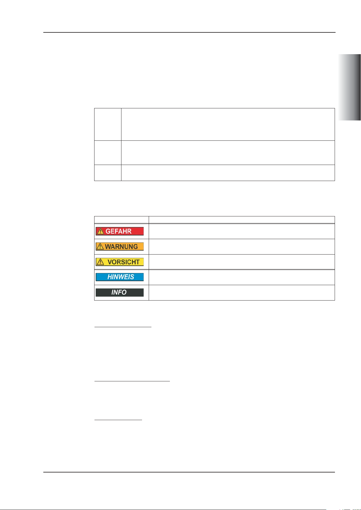
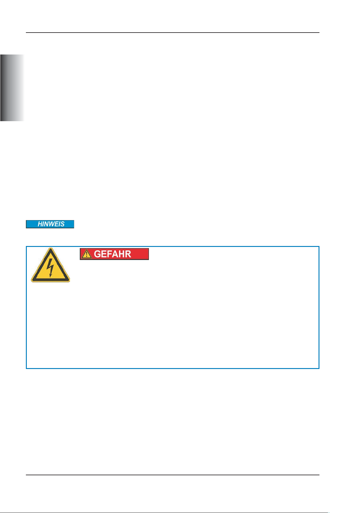
1.2.1 Verwendete Symbole
Symbol Bedeutung
Weist auf eine gefährliche Situation hin, die, *wenn sie nicht vermieden
wird, zum Tode oder zu schweren, irreversiblen Verletzungen führen wird
Weist auf eine gefährliche Situation hin, die, wenn sie nicht vermieden wird,
zum Tode oder zu schweren, irreversiblen Verletzungen führen kann
Weist auf eine gefährliche Situation hin, die, wenn sie nicht vermieden wird,
zu leichten Verletzungen führen kann
Dies ist kein Sicherheits-Symbol. Es weist auf eine Situation hin, die, wenn
sie nicht vermieden wird, zu Beschädigung von Sachen führen kann
Dies ist kein Sicherheits-Symbol. Dieses Symbol weist auf wichtige Informationen hin
1.2.2 Das sollten Sie beachten
Dokumentation lesen
Lesen Sie vor der Montage und Inbetriebnahme die vorliegende Dokumentation. Falsches Handhaben der KCM Module kann zu Personen- oder Sachschäden führen. Der
Betreiber muss daher sicherstellen, dass alle mit Arbeiten an KCM Modulen betrauten
Personen das Handbuch gelesen und verstanden haben und dass die Sicherheitshinweise in diesem Handbuch beachtet werden.
Technische Daten beachten
.
.
.
.
.
Halten Sie die technischen Daten und die Angaben zu den Anschlussbedingungen
(Typenschild und Dokumentation) ein. Wenn zulässige Spannungswerte oder Stromwerte
überschritten werden, können die Module z.B. durch Überhitzung geschädigt werden.
Heiße Oberfläche
Die Module können im Betrieb bis zu 80°C heiß werden. Bei Berührung besteht die
Gefahr leichter Verbrennungen. Beachten Sie die zulässige Einbaulage (senkrecht, Erd
anschlüsse unten) und achten Sie auf ausreichend Abstand (rechts/links > 20mm,
unten/oben>100mm) zu benachbarten Baugruppen.
-
Betriebsanleitung Deutsch - 3
Page 4

KCM Kondensatormodule 01/2014 Kollmorgen
Fachpersonal erforderlich
Nur qualifiziertes Fachpersonal darf Arbeiten wie Transport, Montage, Inbetriebnahme
und Instandhaltung ausführen. Qualifiziertes Fachpersonal sind Personen, die mit Trans
port, Aufstellung, Montage, Inbetriebnahme und Betrieb von Leistungselektronik vertraut
sind und über die ihrer Tätigkeit entsprechenden Mindestqualifikationen verfügen:
Transport: nur durch Personal mit Kenntnissen in der Behandlung
elektrostatisch gefährdeter Bauelemente
DEUTSCH
Mech. Installation: nur durch Fachleute mit maschinenbautechnischer Ausbildung
Elektr. Installation: nur durch Fachleute mit elektrotechnischer Ausbildung
Inbetriebnahme: nur durch Fachleute mit weitreichenden Kenntnissen in
den Bereichen Elektrotechnik / Antriebstechnik
Das Fachpersonal muss ebenfalls IEC 60364 / IEC 60664 und nationale Unfallverhütungsvorschriften kennen und beachten. Aus der Risikobeurteilung des Maschinenherstellers leiten sich eventuell zusätzliche Anforderungen an das Fachpersonal ab.
Erdung
Stellen Sie die ordnungsgemäße Erdung der KCM Module mit der PE-Schiene im Schaltschrank als Bezugspotential sicher. Ohne niederohmige Erdung ist keine personelle
Sicherheit gewährleistet und es besteht Lebensgefahr durch elektrischen Schlag.
-
Hohe Spannungen
Halten Sie während des Betriebs der KCM Module den Schaltschrank geschlossen. Ziehen Sie keine Stecker während des Betriebs, in ungünstigen Fällen können Lichtbögen
entstehen und Personen und Kontakte schädigen. Zwischenkreisanschlüsse können über
eine Stunde nach Abschalten der Netzspannung gefährliche Spannung führen (Selbstentladezeit). Lebensgefahr durch elektrischen Schlag.
Vor Installation oder Deinstallation müssen KCM Module komplett entladen werden. Führen Sie die Entladung wie im Kapitel "Module entladen" beschrieben durch.
Prüfen Sie vor Arbeitsbeginn an den Leistungsanschlüssen der Module die Spannung an
den Anschlussklemmen gegen Erde und gegeneinander auf Spannungsfreiheit.
1.2.3 Bestimmungsgemäße Verwendung
— Die KCM Module dürfen nur an Kollmorgen Servoverstärkern mit 400/480V Nenn-
spannung und maximal 24A Nennstrom angeschlossen werden.
— Die KCM Module werden als Bauteile in elektrische Anlagen oder Maschinen einge-
baut und dürfen nur als integrierte Bauteile in Betrieb genommen werden.
— Die Konformität der KCM Module zu den in der EG-Konformitätserklärung genann-
ten Normen garantieren wir nur, wenn von uns gelieferte Komponenten (Servoverstärker, Motor, Leitungen usw.) verwendet werden.
1.2.4 Nicht bestimmungsgemäße Verwendung
— Der Betrieb der KCM Module ist verboten
- in explosionsgefährdeten Bereichen,
- in Umgebungen mit ätzenden und/oder elektrisch leitenden Säuren, Laugen, Ölen,
Dämpfen, Stäuben.
— Der bestimmungsgemäße Betrieb der KCM Module ist untersagt, wenn die Maschi-
ne, in die sie eingebaut wurden,
- nicht den Bestimmungen der EG Maschinenrichtlinie entspricht,
- nicht die Bestimmungen der EMV- und Niederspannungs-Richtlinien erfüllt.
Deutsch - 4 Betriebsanleitung
Page 5
Kollmorgen 01/2014 KCM Kondensatormodule
1.2.5 Handhabung
1.2.5.1 Transportieren
Klimaklasse 2K3 nach EN61800-2, IEC 60721-3-2
—
Temperatur: -25..+70°C, max. 20K/Stunde schwankend
—
Luftfeuchtigkeit: relative Feuchte 5% ... 95% nicht kondensierend
— Überprüfen Sie bei beschädigter Verpackung das Modul auf sichtbare Schäden.
Informieren Sie den Transporteur und gegebenenfalls den Hersteller.
1.2.5.2 Lagern
— Klimaklasse 1K4 nach EN61800-2, IEC 60721-3-2
— Lagertemperatur -25...+55°C, max. 20K/Stunde schwankend
Luftfeuchtigkeit relative Feuchte 5% ... 95% nicht kondensierend
— Nur in der Originalverpackung des Herstellers, max. Stapelhöhe: 10 Kartons
— Lagerdauer > 1 Jahr: Kondensatoren müssen vor der Inbetriebnahme neu formiert
werden. Lösen Sie alle elektrischen Anschlüsse. Speisen Sie das KCM etwa
1Stunde/Lagerjahr mit max. 200V DC an den Klemmen +/- DC.
DEUTSCH
1.2.5.3 Warten / Reinigen
— Wartung und Reinigung nur von qualifiziertem Personal
— Gehäusereinigung mit Isopropanol o.ä., nicht tauchen oder absprühen
1.2.5.4 Deinstallieren
1. Gerät sicher entladen (siehe Kapitel "KCM Module Entladen" auf S.10)
2. Entladehilfsmittel (Steckbrücke, Verbindungskabel) gesteckt lassen
3. Spannungsfreiheit DC+/DC-, DC+/PE, DC-/PE prüfen
4. Verdrahtung entfernen, KCM Modul demontieren
1.2.5.5 Reparieren / Entsorgen
Reparaturen darf nur der Hersteller durchführen, Öffnen der Geräte bedeutet Verlust der
Gewährleistung. Gemäß der WEEE-2002/96/EG-Richtlinien nehmen wir Altgeräte und
Zubehör zur fachgerechten Entsorgung zurück, sofern die Transportkosten vom Absender übernommen werden. Senden Sie die Geräte zur Reparatur oder Entsorgung an:
KOLLMORGEN Europe GmbH, Pempelfurtstr. 1, D-40880 Ratingen
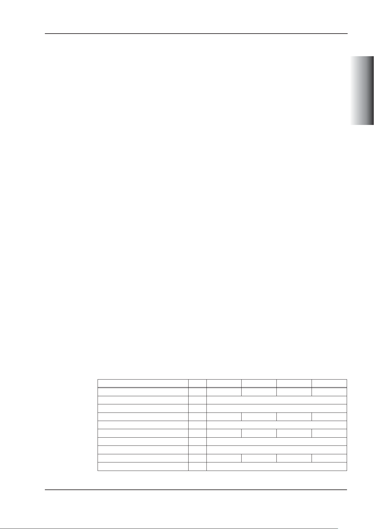
1.3 Technische Daten
Typ DIM KCM-S200 KCM-P200 KCM-E200 KCM-E400
Speicherkapazität
Nenn-Anschlussspannung
Spitzen-Anschlussspannung
Leistung
Schutzart
Einsatzspannung
Anschlussquerschnitt
Maße (HxBxT)
Gewicht
zul. Umgebungstemperatur
Ws 1600 2000 2000 4000
V= max 850
V= max 950 (30s in 6min)
kW 18 18 18 18
IP20
V= ermittelt 470 - -
mm² max. 6
mm 300 x 100 x 201
kg 6,9 6,9 4,1 6,2
°C 0 ... 40
Betriebsanleitung Deutsch - 5
Page 6
KCM Kondensatormodule 01/2014 Kollmorgen
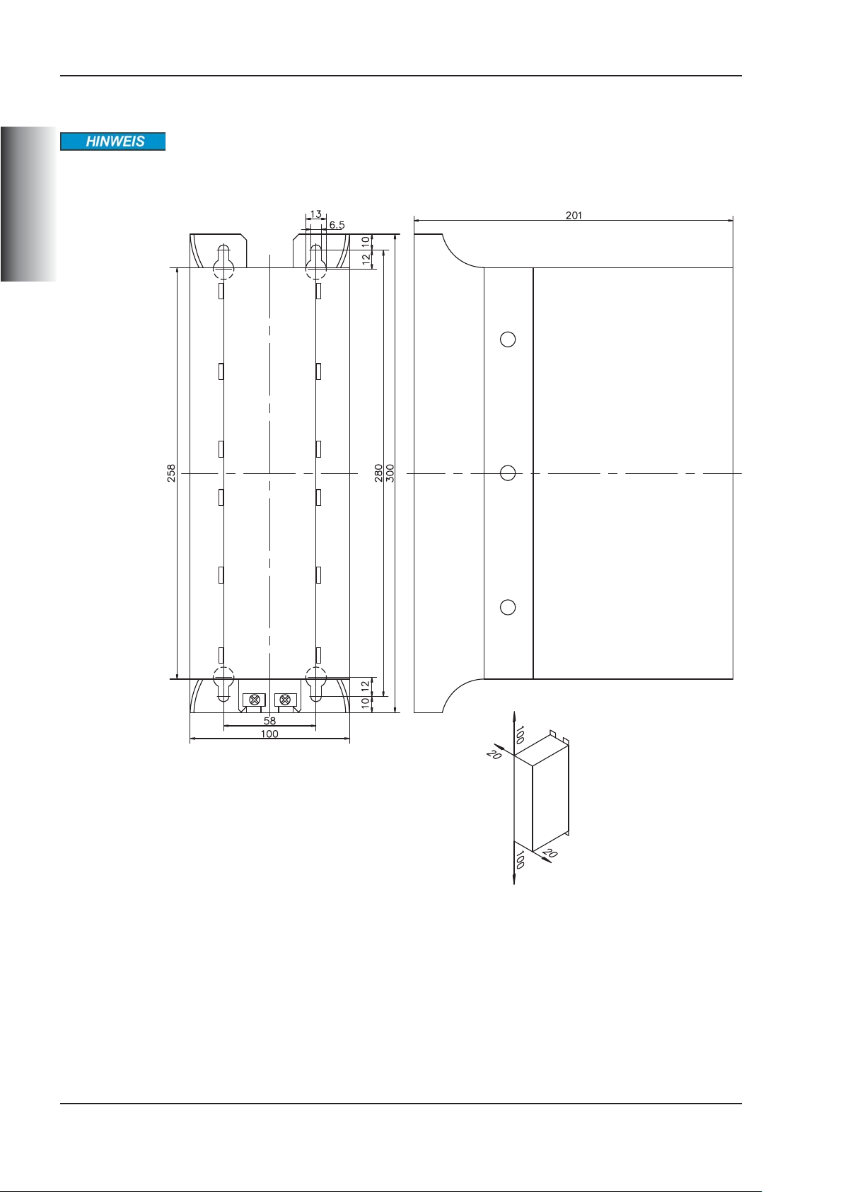
1.4 Mechanische Installation
Zulässige Montageart: Senkrecht, Erdanschlüsse unten. Andere Montagelagen sind nicht
zulässig.
Montagematerial: vier Innensechskant-Schrauben M6.
DEUTSCH
Freiräume einhalten!
Maße in mm, Freimaßtoleranzen nach DIN7168, T1 mittel
Deutsch - 6 Betriebsanleitung
Page 7
Kollmorgen 01/2014 KCM Kondensatormodule
1.5 Elektrische Installation
1.5.1 Anschluss
Zwischenkreisklemmen in Servosystemen führen hohe Gleichspannung
bis zu 900V. Berühren der Klemmen unter Spannung ist lebensgefährlich.
Schalten Sie die Netzspannung ab (freischalten). Sie dürfen nur bei freigeschalteter Anlage an den Anschlüssen arbeiten.
Die Selbstentladezeit der Module kann über eine Stunde betragen. Prüfen
Sie den Ladezustand mit einem für Gleichspannung bis 1000V geeigneten Messgerät. Wenn Sie zwischen den Klemmen DC+/DC- oder gegen
Erde eine Spannung größer als 60V messen, entladen Sie die Module
(siehe Kapitel "KCM Module Entladen" auf S.10).
Maximale Leitungslänge zwischen Servoverstärker und KCM Modul: 500mm.
Verdrillen Sie die Leitungen. Größere Kabellängen erfordern abgeschirmte Leitungen.
Voraussetzung für die folgenden Anweisungen:
- Ordnungsgemäß freigeschaltete, geerdete Anlage.
- KCM Module sind im Schaltschrank montiert.
- Entladehilfsmittel (Steckbrücke, Verbindungskabel) gesteckt wie im Lieferzustand
(Kapazitäten sind dauerhaft mit dem integrierten Entladewiderstand verbunden).
DEUTSCH
KCM-S anschließen (Reihenfolge einhalten!)
1. Schließen Sie als erstes die Schutzerde an.
2. Prüfen Sie die Spannungsfreiheit des Zwischenkreises, an den Sie KCM-S
anschließen wollen.
3. Schließen Sie den BR Anschluss an den Servoverstärker mit den häufigsten
generatorischen Bremsvorgängen im System an. Dieser Servoverstärker muss
einen aktiven internen oder externen Bremswiderstand besitzen.
4. Schließen Sie die DC+/DC- Anschlüsse an den Zwischenkreis an.
Achten Sie auf korrekte Polung, bei Vertauschen von DC+/DCwerden die KCM Module zerstört.
5. Entfernen Sie die Entladehilfsmittel (Steckbrücke).
KCM-P anschließen (Reihenfolge einhalten!)
1. Schließen Sie als erstes die Schutzerde an.
2. Prüfen Sie die Spannungsfreiheit des Zwischenkreises, an den Sie KCM-P
anschließen wollen.
3. Schließen Sie die DC+/DC- Anschlüsse an den Zwischenkreis an.
Achten Sie auf korrekte Polung, bei Vertauschen von DC+/DCwerden die KCM Module zerstört.
4. Entfernen Sie die Entladehilfsmittel (Steckbrücke).
KCM-E anschließen (Reihenfolge einhalten!)
1. Schließen Sie als erstes die Schutzerde an.
2. Das Verbindungskabel vom KCM-E lösen und zum Entladen zwischen
KCM-E/X3 und KCM-S(-P)/X1 stecken. Mindestens 140 s warten.
3. Das Verbindungskabel lösen und zwischen KCM-E/X1 und KCM-S(-P)/X1 stecken.
Betriebsanleitung Deutsch - 7
Page 8
KCM Kondensatormodule 01/2014 Kollmorgen
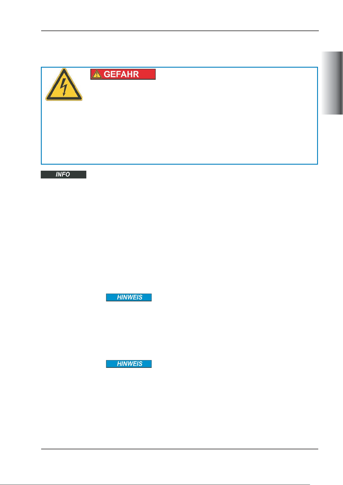
1.5.2 Anschlussbeispiel 1 mit Y-Stecker
Das Beispiel zeigt ein System mit Servoverstärker, KCM-P, KCM-S und KCM-E. Der
Y-Stecker am Kollmorgen Servoverstärker ermöglicht den Anschluss von zwei
KCM-Modulen am Zwischenkreis eines Servoverstärkers.
Die Verbindungen DC+ und DC- sollten immer verdrillt geführt werden (max. 6mm²).
DEUTSCH
Legende:
Kürzel Bedeutung
DC+ Gleichstrom Zwischenkreis positiv
DC- Gleichstrom Zwischenkreis negativ
BR Brems-Chopper
RBint Interner Bremswiderstand
RBintern Chopper Eingang für internen Bremswiderstand
RBext Externer Bremswiderstand
PE Schutzerde
Serielle Schnittstelle X4 zum Anschluss an PC, Gegenstecker liegt bei,
RS422
KCM-P Ready Signal (Klemmen 4,6): Schaltspannung +24V, Widerstand 1...100 kW
gegen Masse. Typische Abfallzeiten auf unter 5V kleiner 4 ms.
Klemme 6 KCM-P Status Mögliche Ursachen
High-Signal Betriebsbereit. Ladevorgang beendet, Spannung im Toleranzbereich.
Low-Signal Nicht betriebsbereit
beliebige Terminalsoftware zur Kommunikation verwenden. Weitere Information finden Sie im Produkt WIKI
Einstellung: 115200 Baud, 8 Data Bits, 1 Stop Bit, No Parity&Flow Control
- KCM-P ist noch im Lademodus
- Netzausfall.
- KCM-P ist defekt.
.
Deutsch - 8 Betriebsanleitung
Page 9
Kollmorgen 01/2014 KCM Kondensatormodule
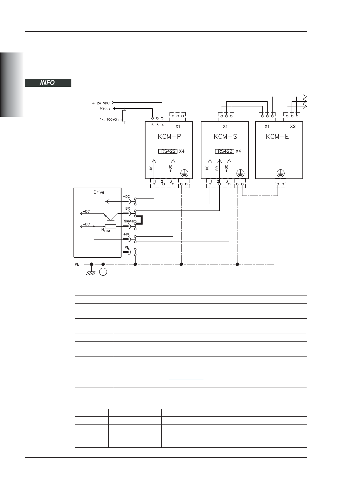
1.5.3 Anschlussbeispiel 2 mit Klemmleiste
Das Beispiel zeigt ein System zwei Servoverstärkern, KCM-P, KCM-S und KCM-E. Die
Verdrahtung erfolgt über verdrillte Leitungen und über eine Klemmleiste.
Die Verbindungen DC+ und DC- sollten immer verdrillt geführt werden (max. 6mm²)
DEUTSCH
Legende:
Kürzel Bedeutung Kürzel Bedeutung
DC+ Gleichstrom Zwischenkreis positiv RBext Externer Bremswiderstand
DC- Gleichstrom Zwischenkreis negativ BR Brems-Chopper
PE Schutzerde RS422 X4 Details siehe Seite 8
Betriebsanleitung Deutsch - 9
Page 10
KCM Kondensatormodule 01/2014 Kollmorgen
1.6 Inbetriebnahme
Voraussetzung für die folgenden Anweisungen:
- Ordnungsgemäß freigeschaltete, geerdete Anlage.
- KCM Module sind im Schaltschrank montiert und verdrahtet.
- Entladehilfsmittel (Steckbrücke, Verbindungskabel) sind entfernt.
- KCM-P: Die Netzausfall-Überwachung muss im Servoverstärker korrekt
parametriert sein.
DEUTSCH
- KCM-S: Last muss angekoppelt sein, die dazu führt, dass beim Abbremsen der
Bremschopper des Servoverstärkers aktiv wird.
Gehen Sie wie folgt vor (Reihenfolge einhalten!):
1. 24V Versorgungsspannung des Servoverstärkers einschalten.
2. Netzspannung einschalten, wenn der Verstärker-Startvorgang beendet ist.
3. KCM-P beginnt den Ladevorgang bei ca. 470V DC, die LED blinkt.
4. Servoverstärker freigeben und ein Fahrprofil fahren, das zum Ansprechen des
Bremschoppers führt.
5. KCM-S ermittelt die Chopperschwelle und beginnt zu laden, die LED blinkt.
1.7 KCM Module entladen
Die jedem Modul beiliegenden Hilfsmittel (Steckbrücke bzw. Verbindungskabel) ermöglichen das sichere Entladen der Module.
Wenn die Lade-LED in der Oberseite der Module blinkt, sind die Kondensatoren geladen.
Die LED ermöglicht jedoch keine sichere Aussage über den Entladezustand, da sie nicht
auf Ausfall überwacht wird.
Zwischenkreisklemmen in Servosystemen führen hohe Gleichspannung
bis zu 900V. Berühren der spannungsführenden Klemmen ist lebensgefährlich. Schalten Sie die Netzspannung ab (Anlage freischalten). Sie
dürfen nur bei freigeschalteter Anlage an den Anschlüssen arbeiten. Prüfen Sie den Ladezustand der Kondensatoren mit einem für Gleichspannung bis 1000V geeigneten Messgerät. Warten Sie, bis die zwischen den
Klemmen DC+/DC- oder gegen Erde gemessene Spannung unter 60V
gesunken ist. Die Selbstentladezeit der Module kann über eine Stunde
betragen. Wenn Sie die Selbstentladezeit nicht abwarten können, müssen Sie die Module zwangsentladen. Halten Sie das unten beschrieben
Vorgehen zur Zwangsentladung der Module unbedingt ein.
Gehen Sie zu Ihrer Sicherheit bei der Zwangsentladung der Module wie folgt vor:
1. Schalten Sie die Netzspannung und 24V Versorgungsspannung ab (freischalten).
2. Entladen Sie die Module (ca. 70s pro Modul):
KCM-S/-P: Steckbrücke in die Schraubklemmen (schwarz-1 <=> grau-2) an der
Unterseite der Module stecken, Steckbrücke stecken lassen.
KCM-E: Mit einem Verbindungskabel an der Oberseite des Moduls die
Stecker X2/X3 brücken, Verbindungskabel stecken lassen.
3. Messen Sie die Spannung +DC/-DC , warten Sie, bis die Spannung unter 60V
gesunken ist.
4. Führen Sie die geplante Aufgabe durch (z.B. Reinigen, Warten oder Deinstallieren).
5. Vor erneuter Inbetriebnahme Steckbrücke bzw. Verbindungskabel lösen und die
Geräte wieder korrekt anschließen.
Deutsch - 10 Betriebsanleitung
Page 11
Kollmorgen 01/2014 KCM Capacitor Modules
2 KCM Capacitor Modules
2.1 General
KCM modules (KOLLMORGEN Capacitor Modules) absorb energy generated by the
motor when it is operating in generator mode. Normally, this energy is dissipated as
waste via brake resistors. KCM modules, however, feed the energy they have stored
back into the DC Bus link as and when it is required.
KCM-S Saves energy: The energy stored in the capacitor module during regenerative
braking is available the next time acceleration happens. The module’s inception voltage is calculated automatically during the first load cycles.
KCM-P Power in spite of power failure: If the power supply fails, the module provides
the servo amplifier with the stored energy that is required to bring the drive to a
standstill in a controlled manner (this only applies to the power supply voltage;
battery-back the 24 V supply separately).
KCM-E Expansion module for both applications. Expansion modules are available in
two capacitance classes.
2.2 Safety
ENGLISH
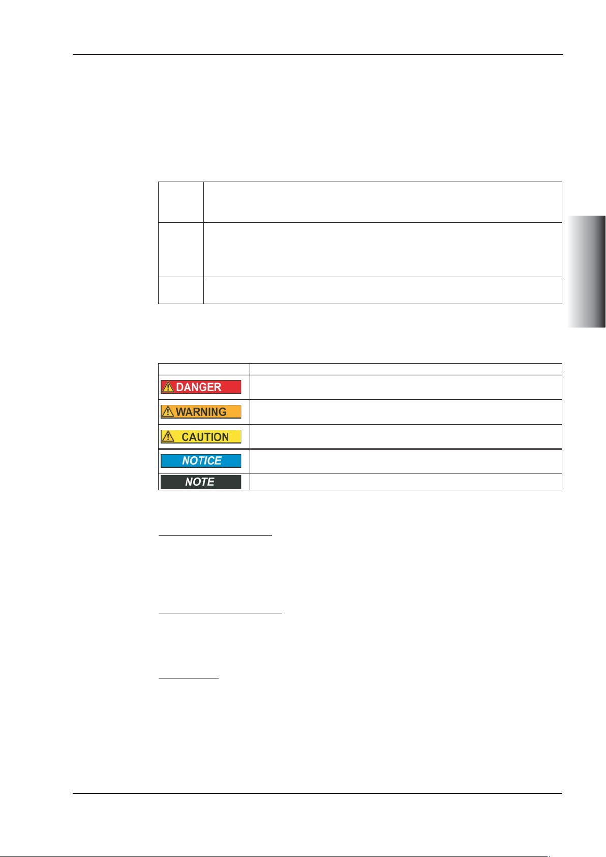
2.2.1 Symbols used
Symbol Indication
Indicates a hazardous situation which, if not avoided, will result in death or
serious injury
Indicates a hazardous situation which, if not avoided, could result in death
or serious injury
Indicates a hazardous situation which, if not avoided, could result in minor
or moderate injury
This is not a safety symbol. This symbol indicates situations which, if not
avoided, could result in property damage
This is not a safety symbol. This symbol indicates important notes.
.
.
2.2.2 You should pay attention to this
Read the documentation!
Read this documentation prior to assembly and commissioning. Incorrect handling of the
KCM modules may lead to personal injury or material damage. The operator must, therefore, ensure that all persons entrusted to work on KCM modules have read and understood the manual and that the safety information in the manual is observed.
Observe the technical data!
Observe the technical data and the information on connection requirements (rating plate
and documentation). If the permissible voltage or current values are exceeded, the modules may be damaged (as a result of overheating, for example).
.
.
Hot surfaces!
The KCM modules can reach temperatures of up to 80°C during operation. Touching
them can result in minor burns. Observe the permissible mounting position (vertical,
ground connections at the bottom) and ensure that a sufficient distance is maintained
from neighboring assemblies (right/left > 20 mm, above/below > 100 mm).
Instruction Manual English - 11
Page 12

KCM Capacitor Modules 01/2014 Kollmorgen
Specialist staff required
Only qualified specialist personnel may carry out work relating to transport, assembly,
commissioning, and maintenance. Qualified specialist personnel are persons who are
familiar with the processes involved in transporting, installing, assembling, commissio
ning, and operating power electronics, and who possess the relevant minimum qualifica
tions for their field:
Transport: Only by personnel with knowledge of handling
electrostatically-sensitive components
Mech. installation: Only by specialists in mechanical engineering
Elec. installation: Only by specialists in electrical engineering
Commissioning: Only by specialists with extensive knowledge in
the fields of electrical engineering/drive technology
The specialist personnel must also observe and be familiar with IEC 60364 / IEC 60664,
as well as national accident prevention regulations. The machine manufacturer’s risk
assessment may result in additional requirements for specialist personnel.
-
-
ENGLISH
Earthing
Ensure that the KCM modules are grounded properly with the PE rail in the switching
cabinet as reference potential. Without low-resistance grounding, personal safety cannot
be guaranteed and there will be a danger of death from electric shock.
High voltages
Ensure that the switching cabinet remains closed while the KCM modules are in operation. Do not remove any connectors during operation as this may cause electrical arcing,
resulting in personal injury and damage to contacts. DC Bus link connections can carry
dangerous voltage levels over an hour after the line voltage has been switched off
(self-discharge time). Danger of death from electric shock.
The KCM modules must be completely discharged prior to installation or uninstallation.
Perform the discharge process as described in the chapter “Discharging KCM modules”.
Before commencing work on the modules’ power terminals, check the voltage at the connection terminals is de-energized to ground and to each other.
2.2.3 Use as directed
— The KCM modules may only be connected to Kollmorgen servo amplifiers with
400/480 V rated voltage and a maximum rated current of 24 A.
— The KCM modules are built into electrical systems or machines as components and
may only be operated as integrated components.
— We only guarantee that the KCM modules conform to the standards referred to in
the EC Declaration of Conformity if the components that we have supplied are used
(servo amplifier, motor, cables, etc.).
2.2.4 Prohibited use
— You must not operate the KCM modules
- in potentially explosive areas
- in areas with corrosive and/or electrically conductive acids, bases, oils, vapors,
or dusts.
— The intended operation of the KCM module is prohibited if the machine in which it
has been installed
- does not correspond to the provisions of the EC Machinery Directive
- does not fulfill the provisions of the EMC Directive and the Low Voltage Directive.
English - 12 Instruction Manual
Page 13

Kollmorgen 01/2014 KCM Capacitor Modules
2.2.5 Handling
2.2.5.1 Transport
Climatic class 2K3 according to EN61800-2, IEC 60721-3-2
—
Temperature: -25 to +70°C, max. 20 K/hour variable
—
Humidity: Relative humidity 5% to 95% non-condensing
— If the packaging is damaged, check the module for visible damage. Inform the cou-
rier and, if necessary, the manufacturer.
2.2.5.2 Storage
— Climatic class 1K4 according to EN61800-2, IEC 60721-3-2
— Storage temperature: -25 to +55?, max. 20 K/hour variable
Humidity: Relative humidity 5% to 95% non-condensing
— Only in the manufacturer’s original packaging, max. stacking height: 10 boxes
— Storage period > 1 year: Prior to commissioning, capacitors must be re-formed. Dis-
connect all electrical connections. Supply the KCM with max. 200 V DC at the
+/- DC terminals for approx. 1 hour per year of storage.
2.2.5.3 Maintenance/Cleaning
— Maintenance and cleaning may only be performed by qualified personnel
— Clean the housing with isopropyl alcohol or similar; do not immerse or spray
2.2.5.4 Uninstallation
1. Discharge the device safely (see chapter “Discharging KCM modules” on p.18)
2. Leave discharge aids (plug-in bridge, connecting cables) plugged in
3. Check that DC+/DC-, DC+/PE, and DC-/PE are de-energized
4. Remove wiring, dismantle KCM module
2.2.5.5 Repairs/Disposal
Repairs must only be performed by the manufacturer; opening the devices will invalidate
the warranty. In accordance with the WEEE-2002/96/EC directives, we take old devices
and accessories back to dispose of them professionally, provided that the transport costs
are borne by the sender. Please send devices for repair or disposal to:
KOLLMORGEN Europe GmbH, Pempelfurtstr. 1, D-40880 Ratingen
ENGLISH
2.3 Technical Data
Type DIM KCM-S200 KCM-P200 KCM-E200 KCM-E400
Storage capacity
Rated supply voltage
Peak supply voltage
Power
Protection class
Inception voltage
Wiring cross section
Dimensions (HxWxD)
Weight
Permissible ambient temp.
Ws 1600 2000 2000 4000
V= max. 850
V= max. 950 (for 30s in 6min)
kW 18 18 18 18
IP20
V= evaluated 470 - -
mm² 6 max.
mm 300 x 100 x 201
kg 6.9 6.9 4.1 6.2
°C 0 ... 40
Instruction Manual English - 13
Page 14

KCM Capacitor Modules 01/2014 Kollmorgen
2.4 Mechanical Installation
Permissible assembly type: Vertical, ground connections at the bottom. Other assembly
positions are not permitted.
Assembly material: Four M6 hexagon head screws.
ENGLISH
Keep space free!
Dimensions in mm, general tolerances according to DIN7168, T1 middle
English - 14 Instruction Manual
Page 15

Kollmorgen 01/2014 KCM Capacitor Modules
2.5 Electrical Installation
2.5.1 Connecting
DC Bus link terminals in servo systems carry high DC voltage of up to
900 V. Touching the terminals while they are carrying voltage is extremely
dangerous. Switch off (disconnect) the line voltage. You must only work
on the connections when the system is disconnected.
It can take over an hour for the modules to self-discharge. Check the state of charge with a measuring device that is suitable for a DC voltage of
up to 1,000 V. When measuring a voltage of over 60 V between the
DC+/DC- terminals or to ground, discharge the modules (see chapter
“Discharging KCM modules” on p.18).
Maximum cable length between servo amplifier and KCM module: 500 mm.
Twist the cables. Longer cable lengths require shielding.
Prerequisite for the following instructions:
- Properly disconnected, grounded system
- KCM modules are assembled in the switching cabinet
- Discharge aids (plug-in bridge, connecting cables) are plugged in as they were
upon delivery.
(Capacitances are permanently connected to the integrated discharge resistor.)
ENGLISH
Connecting the KCM-S (do this in the order specified)
1. First connect the protective ground.
2. Check that the DC Bus to which you wish to connect the KCM-S is de-energized.
3. Connect the BR connection to the servo amplifier with the most frequent
regenerative braking processes in the system. This servo amplifier must have an
active internal or external brake resistor.
4. Connect the DC+/DC- connections to the DC Bus link.
Ensure that the polarity is correct; swapping round DC+/DCwill damage the KCM modules beyond repair.
5. Remove the discharge aids (plug-in bridge).
Connecting the KCM-P (do this in the order specified)
1. First connect the protective ground.
2. Check that the DC Bus to which you wish to connect the KCM-P, is de-energized.
3. Connect the DC+/DC- connections to the DC Bus link.
Ensure that the polarity is correct; swapping round DC+/DCwill damage the KCM modules beyond repair.
4. Remove the discharge aids (plug-in bridge).
Connecting the KCM-E (do this in the order specified)
1. First connect the protective ground.
2. Detach the connecting cable from the KCM-E and plug it in between
KCM-E/X3 and KCM-S(-P)/X1 for discharging purposes. Wait at least 140 s.
3. Detach the connecting cable and plug it in between KCM-E/X1 and KCM-S(-P)/X1.
Instruction Manual English - 15
Page 16

KCM Capacitor Modules 01/2014 Kollmorgen
2.5.2 Example connection 1 with Y connector
This example illustrates a system with a servo amplifier, KCM-P, KCM-S, and KCM-E.
The Y connector on the Kollmorgen servo amplifier allows you to connect two KCM
modules to the DC Bus link of a servo amplifier.
The DC+ and DC- connections should always be twisted, cross section max. 6mm².
ENGLISH
Legend:
Abbreviation Meaning
DC+ DC Bus link positive
DC- DC Bus link negativ
BR Brake Chopper
RBint Internal brake resistor
RBintern Chopper input for internal brake resistor
RBext External brake resistor
PE Protection earth
Serial Interface X4 to connect a PC, mating connector in the package,
RS422
KCM-P Ready Signal (terminal 4,6) : Voltage supply +24V, resistor 1...100 kW to GND.
Typical switch-off time to a voltage below 5V: less than 4 ms.
Terminal 6 KCM-P Status Possible causes
High-Signal Ready to operate Capacitors loaded, voltage inside tolerance
Low-Signal Not ready to operate
use a terminal software to transmit/receive the data.
More information see Product WIKI
Setting: 115200 Baud, 8 Data Bits, 1 Stop Bit, No Parity&Flow Control
- KCM-P is still in mode "loading"
- Mains supply fault.
- KCM-P is faulty.
.
English - 16 Instruction Manual
Page 17

Kollmorgen 01/2014 KCM Capacitor Modules
2.5.3 Example connection 1 with terminal strip
This example illustrates a system with two servo amplifiers and a KCM-P, KCM-S, and
KCM-E. The wiring uses twisted cables and a terminal strip.
The DC+ and DC- connections should always be twisted, cross section max. 6mm².
ENGLISH
Legend:
Abbr. Meaning Abbr. Meaning
DC+ DC Bus link positive BR Brake Chopper
DC- DC Bus link negative RBext External brake resistor
PE Protective Earth RS422 X4 Details see page 16
Instruction Manual English - 17
Page 18

KCM Capacitor Modules 01/2014 Kollmorgen
2.6 Setup
Prerequisite for the following instructions:
- Properly disconnected, grounded system
- KCM modules are assembled and wired in the switching cabinet
- Discharge aids (plug-in bridge, connecting cables) are removed
- KCM-P: The power failure monitoring must be parameterized correctly in
the servo amplifier
- KCM-S: The load that leads to the activation of the servo amplifier’s brake
chopper during braking must be connected.
Proceed as follows (do this in the order specified):
1. Switch on the 24V supply voltage of the servo amplifier.
2. Switch on the line voltage, after the 24V boot process has finished.
3. The KCM-P begins the charging process at approx. 470 V DC; the LED flashes.
4. Enable the servo amplifier and operate the driving profile that causes the
brake chopper to respond
5. The KCM-S determines the chopper threshold and begins to charge; LED flashes.
ENGLISH
2.7 Discharging KCM modules
The aids supplied with each module (plug-in bridge/connecting cables) allow you to
discharge the modules safely.
When the charging LED on top of the modules flashes, the capacitors are charged.
Please note, however, that the LED does not safely indicate the real state of discharge,
as it is not supervised for failures.
DC Bus link terminals in servo systems carry high DC voltage of up to
900 V. Touching the terminals while they are carrying voltage is extremely dangerous. Switch off the line voltage (disconnect the system). You
must only work on the connections when the system is disconnected.
Check the state of charge of the capacitors with a measuring device that
is suitable for a DC voltage of up to 1,000 V. Wait until the voltage measured between the DC+/DC- terminals or to ground dropped below 60 V.
It can take over an hour for the modules to self-discharge. If you cannot
wait for the duration of the self-discharge time, you must force the modules to discharge. You must follow the procedure described below when
forcing the modules to discharge.
For your own safety, proceed as follows when forcing the modules to discharge:
1. Switch off (disconnect) the line voltage and 24V supply.
2. Discharge the modules (approximately 70 s per module):
KCM-S/-P: Insert the plug-in bridge in the screw terminals (black-1 <=> gray-2)
on the base of the modules. Leave the plug-in bridge in place.
KCM-E: Bridge the X2/X3 connector with a connecting cable on the top of
the module. Leave the connecting cable in place.
3. Measure the +DC/-DC voltage and wait until voltage dropped below 60 V.
4. Perform the scheduled task (e.g., cleaning, maintenance, or uninstallation).
5. Remove the plug-in bridge respectively the connection cable before recommissioning.
English - 18 Instruction Manual
Page 19

Kollmorgen 01/2014 KCM Moduli Condensatore
3 KCM Moduli Condensatore
3.1 Informazioni generali
I moduli KCM (KOLLMORGEN Capacitor Module) assorbono energia generata dal
motore in modalità generatore. Di regola questa energia viene convertita in potenza dissipata attraverso resistenze di frenatura esterne. I moduli KCM alimentano l’energia accumulata al circuito DC-link, quando è necessario.
KCM-S Sistema di risparmio energetico: L’energia accumulata nel modulo condensa-
tore durante la frenata rigenerativa è a disposizione per l’accelerazione successiva. La tensione d’esercizio del modulo viene rilevata automaticamente
durante i primi cicli di caricamento.
KCM-P Potenza anche in caso di caduta di alimentazione: In assenza di alimentazio-
ne di potenza il modulo fornisce al servoamplificatore l’energia accumulata per
un arresto controllato dell’azionamento (solo tensione di alimentazione, 24 V
accumulo separato).
KCM-E Espansione del modulo per entrambi gli utilizzi. I moduli di espansione sono
disponibili in due livelli di capacità.
3.2 Sicurezza
3.2.1 Simboli utilizzati
Symbolo Significato
Segnala una situazione di pericolo che, se non evitata, comporta la morte o
lesioni gravi e permanenti
Segnala una situazione di pericolo che, se non evitata, può comportare la
morte o lesioni gravi e permanenti
Segnala una situazione di pericolo che, se non evitata, può comportare infortuni leggeri
Questo non è un simbolo di sicurezza, ma serve a segnala una situazione
di pericolo che, se non evitata, può comportare danni materiali
Questo non è un simbolo di sicurezza, ma serve a segnalare informazioni
importanti
.
.
.
3.2.2 Si dovrebbe prestare attenzione a questo
Leggere la documentazione
Prima di procedere al montaggio e alla messa in funzione leggere attentamente la presente documentazione. L’errata manipolazione dei moduli KCM può comportare danni a
persone o a cose. L’operatore è quindi tenuto ad assicurarsi che tutto il personale
addetto a lavori sui moduli KCM abbia letto e compreso il manuale e che le indicazioni di
sicurezza riportate nel manuale siano rispettate.
Rispettare i dati tecnici
.
.
ITALIANO
Rispettare i dati tecnici e le indicazioni sulle condizioni di collegamento (targhetta di omologazione e documentazione). Se si superano i valori di tensione e di corrente ammessi, i
moduli possono essere danneggiati, ad esempio a causa del surriscaldamento.
Superfici calde
In corso di funzionamento i moduli possono raggiungere temperature fino a 80°C. In caso
di contatto sussiste il pericolo di ustioni lievi. Rispettare la posizione di montaggio con
sentita (perpendicolare, collegamenti a terra sotto) e assicurare la debita distanza
(destra/sinistra > 20 mm, sotto/sopra >100 mm) rispetto ai componenti adiacenti.
-
Manuale di Istruzioni Italiano - 19
Page 20

KCM Moduli Condensatore 01/2014 Kollmorgen
Interventi riservati al personale qualificato
I lavori di trasporto, montaggio, messa in funzione e manutenzione si possono affidare
esclusivamente a personale tecnico qualificato, che abbia familiarità con il trasporto,
l’installazione, il montaggio, la messa in funzione e il funzionamento di componenti elet
tronici e che disponga di opportune qualifiche di base per lo svolgimento di tali attività.
Trasporto: solo da parte di personale con conoscenze in materia di
elementi costruttivi a rischio di scariche elettrostatiche
Installazione meccanica: solo da parte di personale con una formazione meccanica
Installazione elettrica: solo da parte di tecnici con formazione elettrotecnica
Messa in funzione: solo da parte di tecnici con ampie conoscenze nei
nei settori dell’elettrotecnica e dei sistemi di azionamento
Il personale qualificato deve inoltre conoscere e rispettare le norme IEC 60364 / IEC
60664 nonché le disposizioni antinfortunistiche nazionali. L’analisi dei rischi del
produttore potrebbe comportare la necessità di ulteriori requisiti per il personale tecnico.
Messa a terra
Assicurare la regolare messa a terra dei moduli KCM con la bandella PE all’interno
dell’armadio di distribuzione come potenziale di riferimento. Senza una messa a terra a
bassa impedenza non viene garantita la sicurezza personale e sussiste pericolo di morte
per scosse elettriche.
-
Alta tensione
Si raccomanda inoltre di tenere chiuso il quadro elettrico ad armadio durante il funzionamento dei moduli KCM. Non staccare nessun connettore durante il funzionamento: in
casi sfavorevoli possono venire a crearsi archi voltaici con conseguenti danni a carico di
persone e contatti. I collegamenti del circuito DC-link possono condurre tensione perico-
ITALIANO
losa oltre un’ora dopo la disinserzione della tensione di rete (tempo di autoscarica). Pericolo di morte per scosse elettriche.
Prima dell’installazione o della disinstallazione i moduli KCM devono essere completamente scarichi. Effettuare la scarica secondo le indicazioni riportate nel capitolo
“Scaricare i moduli”.
Prima di iniziare i lavori sui collegamenti di potenza dei moduli controllare la tensione dei
morsetti verso terra e l’assenza di tensione tra i morsetti..
3.2.3 Uso conforme
— I moduli KCM devono essere collegati solo a servoamplificatori Kollmorgen con una
tensione nominale di 400/480V e una corrente nominale massima di 24A.
— I motori KCM vengono montati come componenti su impianti elettrici o macchine e
possono essere messi in funzione solo come componenti integrati dell’impianto.
— Garantiamo la conformità dei moduli KCM alle norme menzionate nella dichiarazio-
ne di conformità CE solo se vengono utilizzati componenti originali (servoamplificatori, motore, cavi, e così via).
3.2.4 Uso non conforme
— Il funzionamento dei moduli KCM non è consentito
- in ambienti a rischio di esplosione,
- in ambienti con oli, vapori, polveri, soluzioni alcaline, acidi corrosivi e/o conduttivi.
—
L’uso conforme dei moduli KCM non è possibile, se la macchina in cui sono montati,
- non rispetta i requisiti imposti dalla Direttiva macchine CE,
- non soddisfa i requisiti imposti dalla Direttiva in materia di compatibilità
elettromagnetica.
Italiano - 20 Manuale di Istruzioni
Page 21

Kollmorgen 01/2014 KCM Moduli Condensatore
3.2.5 Manipolazione
3.2.5.1 Trasporto
Classe climatica 2K3 secondo EN61800-2, IEC 60721-3-2
—
Temperatura: -25...+70°C, variazione max. 20K/ora
—
Umidità dell’aria: umidità relativa 5% ... 95% senza condensa
— In caso di imballaggio danneggiato, verificare che il modulo non presenti danni. In-
formarne il trasportatore ed eventualmente il produttore.
3.2.5.2 Stoccaggio
— Classe climatica 1K4 secondo EN61800-2, IEC 60721-3-2
— Temperatura di stoccaggio -25...+55°C, variazione max. 20K/ora
Umidità atmosferica umidità relativa 5% ... 95% senza condensa
— Solo nell’imballaggio originale del produttore, altezza impilamento max: 10 cartoni
— Durata stoccaggio > 1 anno: I condensatori devono essere ricondizionati prima
della messa in funzione. A questo scopo, allentare tutti i collegamenti elettrici. Ali-
mentare il KCM circa 1 ora/anno di stoccaggio con max. 200VDC ai morsetti +/- DC.
3.2.5.3 Manutenzione e pulizia
— Devono essere eseguite solo da personale qualificato.
— Pulizia alloggiamento con isopropanolo o simili, non immergere o nebulizzare
3.2.5.4 Disinstallazione
1. Scaricare l’apparecchio in modo sicuro (cfr. capitolo “Scaricare moduli KCM” a p.26)
2. Lasciare inseriti gli strumenti appositi (ponticello, cavo di collegamento)
3. Controllare l’assenza di tensione DC+/DC-, DC+/PE, DC-/PE
4. Rimuovere il cablaggio, smontare il modulo KCM
3.2.5.5 Riparazione / Smaltimento
Le riparazioni possono essere effettuate unicamente dal fabbricante; l’apertura
dell’apparecchio annulla automaticamente la garanzia. Ai sensi della direttiva RAEE
2002/96/CE ritiriamo vecchi dispositivi e accessori e ne assicuriamo lo smaltimento
sicuro, ma i costi di trasporto restano a carico del mittente. Per la riparazione o lo smaltimento spedire gli apparecchi a:
KOLLMORGEN Europe GmbH, Pempelfurtstr. 1, D-40880 Ratingen
3.3 Dati tecnici
Tipo DIM KCM-S200 KCM-P200 KCM-E200 KCM-E400
Capacità
Tensione di aliment. nominale
Tensione di aliment. picco
Potenza
Grado di protezione
Tensione d’esercizio
Sezione trasversale
Dimensioni (AxLxP)
Peso
Temp. ambiente consentita
ITALIANO
Ws 1600 2000 2000 4000
V= max 850
V= max 950 (30s in 6min)
kW 18 18 18 18
IP20
V= valorizzato 470 - -
mm² 6 max.
mm 300 x 100 x 201
kg 6,9 6,9 4,1 6,2
°C 0 ... 40
Manuale di Istruzioni Italiano - 21
Page 22

KCM Moduli Condensatore 01/2014 Kollmorgen
3.4 Installazzione meccanica
Tipo di montaggio consentito: Perpendicolare, collegamenti a terra sotto. Non sono con
sentite altre posizioni di montaggio.
Materiale di montaggio: quattro viti con esagono incassato M6
-
ITALIANO
Lasciare lo spazio
necessario
Dimensioni in mm, tolleranze secondo DIN7168, T1 medio
Italiano - 22 Manuale di Istruzioni
Page 23

Kollmorgen 01/2014 KCM Moduli Condensatore
3.5 Installazione elettrica
3.5.1 Collegamento
I morsetti del circuito DC-link nei servosistemi conducono una tensione
continua fino a 900 V. In caso di contatto con i morsetti sotto tensione
sussiste pericolo di morte. Scollegare la tensione di rete (mettere fuori
tensione). Lavorare sui collegamenti solo in assenza di tensione.
I moduli possono richiedere più di un’ora per l’autoscarica. Controllarne
quindi lo stato con un dispositivo adatto alla misurazione della tensione
continua fino a 1000 V. Se tra i morsetti DC+/DC- o verso terra viene rilevata una tensione superiore a 60 V, scaricare i moduli (cfr. capitolo “Scaricare i moduli KCM” a pag.26).
Lunghezza massima cavo tra servoamplificatore e modulo KCM: 500 mm.
Intrecciare i cavi. Per lunghezze maggiori sono necessari cavi schermati.
Presupposti per le seguenti indicazioni:
- Impianto opportunamente messo a terra, fuori tensione.
- I moduli KCM sono montati nel quadro elettrico ad armadio.
- Lasciare inseriti gli apparecchi necessari per scaricare il modulo (ponticello, cavo
di collegamento) come al momento della consegna (le capacità sono collegate in
modo duraturo con la resistenza di scarica integrata).
Collegare il KCM-S (rispettare la sequenza indicata!)
1. Collegare prima la terra di protezione.
2. Verificare l’assenza di tensione nel circuito DC-link a cui si desidera collegare
il KCM-S.
3. Collegare il collegamento BR al servoamplificatore con i processi di frenata
rigenerativa più frequenti nel sistema. Questo servoamplificatore deve possedere
una resistenza di frenata attiva interna ed esterna.
4. Collegare i collegamenti DC+/DC- al circuito DC-link
Accertarsi che la polarità sia corretta: in caso contrario
(se si scambiano DC+/DC-) i moduli KCM saranno distrutti.
5. Rimuovere gli strumenti per scaricare il modulo (ponticello).
Collegare il KCM-P (rispettare la sequenza indicata!)
1. Collegare prima la terra di protezione.
2. Verificare l’assenza di tensione nel circuito intermedio a cui si desidera
collegare il KCM-P.
3. Collegare i collegamenti DC+/DC- al circuito DC-link
Accertarsi che la polarità sia corretta: in caso contrario
(se si scambiano DC+/DC-) i moduli KCM saranno distrutti.
4. Rimuovere gli strumenti per scaricare il modulo (ponticello).
Collegare il KCM-E (rispettare la sequenza indicata!)
1. Collegare prima la terra di protezione.
2. Staccare il cavo di collegamento del KCM-E e inserirlo tra KCM-E/X3 e
KCM-S(-P)/X1 per scaricare. Aspettare almeno 140 secondi.
3. Staccare il cavo di collegamento e inserirlo tra KCM-E/X1 e KCM-S(-P)/X1.
ITALIANO
Manuale di Istruzioni Italiano - 23
Page 24

KCM Moduli Condensatore 01/2014 Kollmorgen
3.5.2 Esempio di collegamento 1 con connettore Y
L’esempio mostra un sistema con servoamplificatore, KCM-P, KCM-S e KCM-E. Il con
nettore Y sui servoamplificatori Kollmorgen consente di collegare due moduli KCM al cir
cuito DC-link di un servoamplificatore.
II collegamenti DC+ e DC- devono essere sempre intrecciati, max. 6mm².
-
-
ITALIANO
Legenda:
Abbr. Significato
DC+ Corrente continua circuito DC-link positiva
DC- Corrente continua circuito DC-link negativa
BR Chopper di frenatura
RBint Resistenza di frenatura interna
RBintern Ingresso chopper per resistenza di frenatura interna
RBext Resistenza di frenatura esterna
PE Terra di protezione
Interfaccia seriale X4 per il collegamento al PC, presa femmina in dota-
RS422
Segnale Ready KCM-P (morsetti 4,6): Tensione di collegamento +24V, resistenza
1...100 kW a massa. Tipici tempi di discesa al di sotto di 5V inferioria4ms.
Morsetto 6 Stato del KCM-P Possibili cause
Segnale
High
Segnale
Low
zione, utilizzare qualsiasi software terminale per la comunicazione. Ulteriori informazioni sono reperibili nella sezione Product WIKI
Impostazione: 115200 baud, 8 bit dati, 1 bit stop, no parity&flow control
Pronto per l'uso
Non pronto per
l’uso
Processo di carica terminato, tensione nell’area di tolle
ranza.
- Il KCM-P è ancora in modalità di carica.
- caduta dell’alimentazione di rete.
- il KCM-P è guasto.
.
-
Italiano - 24 Manuale di Istruzioni
Page 25

Kollmorgen 01/2014 KCM Moduli Condensatore
3.5.3 Esempio di collegamento 2 con morsettiera
L’esempio mostra un sistema con due servoamplificatori, KCM-P, KCM-S e KCM-E. Il
cablaggio avviene mediante cavi intrecciati e una morsettiera.
II collegamenti DC+ e DC- devono essere sempre intrecciati, max. 6mm².
Legenda:
Abbr. Significato Abbr. Significato
DC+ Corrente DC circuito DC-link + BR Chopper di frenatura
DC- Corrente DC circuito DC-link - RBext Resistenza di frenatura esterna
PE Terra di protezione RS422 X4 Per i dettagli vedi pagina 24
ITALIANO
Manuale di Istruzioni Italiano - 25
Page 26

KCM Moduli Condensatore 01/2014 Kollmorgen
3.6 Messa in funzione
Presupposti per le seguenti indicazioni:
- Impianto opportunamente messo a terra, fuori tensione.
- I moduli KCM sono montati nel quadro elettrico ad armadio e cablati.
- Gli strumenti per la scarica (ponticello, cavo di collegamento) sono stati rimossi.
- KCM-P: Il controllo dell’assenza di alimentazione deve essere correttamente
parametrizzato nel servoamplificatore.
- KCM-S: Il carico deve essere accoppiato, quindi in caso di frenata
il chopper del servoamplificatore viene attivato.
Procedere nel modo seguente (rispettare la sequenza indicata!):
1. Inserta la tensione di 24V del servoamplificatore.
2. Inserire la tensione di rete, se la partenza del amplificatore è stato completato.
3. Il KCM-P inizia il processo di caricamento a circa 470V DC, il LED lampeggia.
4. Abilitare il servoamplificatore e scegliere la configurazione che determina una
reazione del chopper di frenatura
5. Il KCM-S rileva la soglia del chopper e inizia a caricare, il LED lampeggia.
3.7 Scaricare i moduli KCM
Tutti gli strumenti allegati a ogni modulo (ponticello e cavo di collegamento) permettono di
scaricare in sicurezza i moduli.
ITALIANO
Quando il LED di caricamento nella parte superiore del modulo lampeggia, i condensatori
sono caricati. Il LED non permette di stabilire tuttavia quando sono effettivamente scarichi, poiché non viene monitorata l’assenza di alimentazione.
I morsetti del circuito DC-link nei servosistemi conducono una tensione
continua fino a 900 V. In caso di contatto con i morsetti sotto tensione
sussiste pericolo di morte
. Scollegare la tensione di rete (scollegare
l’impianto). Lavorare sui collegamenti solo in assenza di tensione. Controllare quindi la condizione dei condensatori con un dispositivo adatto
alla misurazione della tensione continua fino a 1000 V. Attendere finché
la tensione rilevata tra i morsetti DC+/DC- o verso terra è scesa sotto i
60 V. I moduli possono richiedere più di un’ora per l’autoscarica. Se non
è possibile aspettare il tempo necessario, i moduli devono essere scaricati in modo forzato. Rispettare assolutamente il procedimento sotto
indicato per scaricare i moduli in modo forzato.
Per scaricare i moduli in modo forzato, procedere per sicurezza come segue:
1. Scollegare la tensione di rete e la tensione di 24V (mettere fuori tensione).
2. Scaricare i moduli (almeno 70s per modulo):
KCM-S/-P: Inserire il ponticello nei morsetti a vite (nero-1 <=> grigio-2) sul lato
inferiore dei moduli, lasciare inserito il ponticello.
KCM-E: Con un cavo di collegamento sul lato superiore del modulo
collegare a ponte il connettore X2/X3, lasciare inserito il cavo di
collegamento.
3. Misurare la tensione DC+/DC-, attendere fino a quando il valore è sceso al di sotto di
60V.
4. Eseguire gli interventi previsti (per esempio pulizia, manutenzione o disinstallazione).
5. Prima della successiva messa in funzione rimuovere nuovamente il ponticello.
Italiano - 26 Manuale di Istruzioni
Page 27

Kollmorgen 01/2014 KCM Módulos de Condensadores
4 KCM Módulos de Condensadores
4.1 Generalidades
Los módulos KCM (KOLLMORGEN Capacitor Module) reciben la energía generada por
el motor durante el funcionamiento de generación. Normalmente, esta energía se convierte en potencia perdida mediante las resistencias de freno. Los módulos KCM suministran la energía acumulada de vuelta al circuito intermedio cuando se necesita.
KCM-S Supone un ahorro de energía: la energía acumulada en el módulo de conden-
sadores durante el frenado de generación está disponible para el próximo
caso de aceleración. La tensión de bloqueo del módulo se determina
automáticamente durante los primeros ciclos de carga.
KCM-P Potencia a pesar de caídas de la red: en caso de una caída del suministro de
potencia, el módulo pone la energía acumulada a disposición del servoamplificador para una detención controlada del accionamiento (solo tensión de potencia, compensación de 24 V por separado).
KCM-E El módulo de ampliación para ambos usos previstos: los módulos de ampliaci-
ón están disponibles en dos clases de capacidad.
4.2 Seguridad
4.2.1 Símbolos utilizados
Símbolos Indication
Indica una situación peligrosa que, si no se evita, ocasionará la muerte
o lesiones graves
Indica una situación peligrosa que, si no se evita, puede ocasionar la
muerte o lesiones graves
Indica una situación peligrosa que, si no se evita, puede ocasionar lesiones leves o moderadas
Éste no es un símbolo de seguridad. Indica situaciones que, si no se
evitan, pueden provocar daños materiales
Éste no es un símbolo de seguridad. Este símbolo indica notas impor-
.
tantes
4.2.2 Lo que se debe tener en cuenta
Leer la documentación
Lea la presente documentación antes del montaje y la puesta en funcionamiento. La
manipulación incorrecta de los módulos KCM puede provocar daños personales o materiales. Por este motivo, el operador debe asegurarse de que todas las personas que
vayan a realizar trabajos en los módulos KCM hayan leído y comprendido el manual, así
como de que se cumplan las instrucciones de seguridad de este manual.
Observar los datos técnicos
Respete los datos técnicos y las indicaciones referentes a las condiciones de conexión
(placa de identificación y documentación). Si se superan los valores de tensión o los
valores de corriente admitidos, los módulos pueden resultar dañados, p. ej., por
sobrecalentamiento.
.
.
.
.
ESPAÑOL
Superficie caliente
Los módulos se pueden calentar durante su funcionamiento hasta alcanzar los 80 °C. Si
se tocan, existe peligro de quemaduras leves. Observe la posición de montaje admitida
(vertical, conexiones a tierra en la parte inferior) y mantenga una distancia suficiente
(derecha/izquierda > 20 mm, abajo/arriba > 100 mm) con las unidades adyacentes.
Manual de instrucciones Español - 27
Page 28

KCM Módulos de Condensadores 01/2014 Kollmorgen
Personal cualificado requerido
Las operaciones de transporte, montaje, puesta en funcionamiento y mantenimiento solo
podrán ser realizadas por personal cualificado. Se entiende por personal cualificado
aquellas personas que están familiarizadas con el transporte, la instalación, el montaje,
la puesta en funcionamiento y el manejo de la electrónica de potencia y que disponen de
las correspondientes cualificaciones mínimas relativas a su actividad:
Transporte: solo a cargo de personal con conocimientos de manejo de elementos de
montaje con riesgo electrostático
Instalación mecánica: solo a cargo de personal con formación en ingeniería mecánica
Instalación eléctrica: solo a cargo de personal con formación en electrotecnia
Puesta en funcion.: solo a cargo de personal con amplios conocimientos en los secto-
res de la electrotecnia y la técnica de accionamientos
El personal especializado debe conocer y tener en cuenta las siguientes normas:
IEC 60364 / IEC 60664 y las normativas nacionales de prevención de accidentes. A partir
de la evaluación de riesgos del fabricante de la máquina es posible que se deriven otros
requisitos adicionales para el personal cualificado.
Toma de tierra
Asegúrese de establecer la toma de tierra correcta de los módulos KCM con la barra de
conductor protector en el bastidor de distribución como potencial de referencia. Sin una
toma de tierra de baja impedancia no se garantiza la seguridad personal y existe peligro
de muerte por descarga eléctrica.
Tensiones altas
Mantenga cerrado el bastidor de distribución durante el funcionamiento de los módulos
KCM. No saque ningún enchufe durante el funcionamiento; en caso de accidente se pueden generar chispazos que causen lesiones personales y daños en los contactos. Las
conexiones de circuito intermedio pueden seguir produciendo tensiones peligrosas una
hora después de haber desconectado la tensión de la red (tiempo de autodescarga).
Peligro de muerte por descarga eléctrica. Antes de la instalación o la desinstalación se
han de descargar completamente los módulos KCM. Realice la descarga como se describe en el capítulo “Descargar los módulos”.
Antes de comenzar los trabajos en las conexiones de potencia de los módulos, compruebe que no haya tensión en los terminales de conexión a tierra y entre sí.
4.2.3 Utilización conforme
— Los módulos KCM solo se pueden conectar a los servoamplificadores Kollmorgen
ESPAÑOL
con tensión nominal de 400/480 V y corriente nominal de 24 A como máximo.
— Los módulos KCM se montan como componentes de instalaciones o máquinas
eléctricas y solo pueden ponerse en funcionamiento como componentes integrados.
— Garantizamos la conformidad de los módulos KCM con las normas enunciadas en
la declaración de conformidad CE, siempre y cuando se empleen componentes suministrados por nosotros (servoamplificador, motor, conductores, etc.).
4.2.4 Uso indebido
— No se permite el uso de los módulos KCM
- en áreas con peligro de explosión,
- en entornos con partículas en suspensión, vapores, aceites, lejías o ácidos
conductores de la electricidad y/o corrosivos.
—
Está prohibido utilizar los módulos KCM si la máquina en la que están instalados:
- no cumple las disposiciones de la directiva comunitaria sobre máquinas,
- no cumple las disposiciones de las directivas sobre la compatibilidad electromag
nética y sobre equipos de baja tensión.
-
Español - 28 Manual de instrucciones
Page 29

Kollmorgen 01/2014 KCM Módulos de Condensadores
4.2.5 Manipulación
4.2.5.1 Transporte
Clase de clima 2K3 según EN61800-2, IEC 60721-3-2
—
Temperatura: -25 ... +70 °C, oscilación máx. 20K/hora
—
Humedad del aire: humedad relativa 5 % ... 95 % sin condensar
— En caso de que el embalaje esté dañado, compruebe que el módulo no tiene daños
visibles. Informe de ello al transportista y, en caso necesario, al fabricante.
4.2.5.2 Almacenamiento
— Clase de clima 1K4 según EN61800-2, IEC 60721-3-2
— Temperatura de almacenamiento -25 ... +55 °C, oscilación máx.20K/hora
Humedad del aire: humedad relativa 5 % ... 95 % sin condensar
— Solo en el embalaje original; altura máx. de apilamiento: 10 cajas de cartón
— Tiempo de almacenamiento > 1 año: antes de la puesta en servicio, los condensa-
dores se deben cargar de nuevo. Desconecte todas las conexiones eléctricas. Ali-
mente el KCM aprox. 1 hora/año de almacenamiento con un máx. de 200 V CC en
los terminales +/- DC.
4.2.5.3 Mantenimiento/limpieza
Los trabajos de mantenimiento y limpieza solo los puede realizar personal cualificado.
Limpieza de la carcasa con isopropanol o similares; no sumergir ni pulverizar
4.2.5.4 Desinstalación
1. Descargar el aparato de forma segura (véase el capítulo “Descarga..." en la p.34)
2. Dejar insertado el medio auxiliar de descarga (puente de conexión, cable de conexión)
3. Comprobar que no haya tensión DC+/DC-, DC+/PE, DC-/PE
4. . Retirar el cableado, desmontar el módulo KCM
4.2.5.5 Reparación/eliminación
Solo el fabricante puede ejecutar reparaciones; la apertura de los aparatos invalida la
garantía. De conformidad con la directiva 2002/96/CE (RAEE), nos encargamos de eliminar de manera adecuada los aparatos y accesorios viejos si el remitente se hace cargo
de los gastos de transporte.
Para su reparación o eliminación, envíe los aparatos a la siguiente dirección:
KOLLMORGEN Europe GmbH, Pempelfurtstr. 1, D-40880 Ratingen
4.3 Datos técnicos
Tipo DIM KCM-S200 KCM-P200 KCM-E200 KCM-E400
Capacidad de almacenamiento
Tensión de conexión nominal
Tensión de conexión máxima
Potencia
Tipo de protección
Umbral de voltaje
Sección transversal
Dimensiones (HxBxT)
Peso
Temp. ambiental admisible
ESPAÑOL
Ws 1600 2000 2000 4000
V= max 850
V= max 950 (30s in 6min)
kW 18 18 18 18
IP20
V= evaluado 470 - -
mm² 6 max.
mm 300 x 100 x 201
kg 6,9 6,9 4,1 6,2
°C 0 ... 40
Manual de instrucciones Español - 29
Page 30

KCM Módulos de Condensadores 01/2014 Kollmorgen
4.4 Instalación mecánica
Tipo de montaje admitido: vertical, conexiones a tierra en la parte inferior. No se admiten
otras posiciones de montaje.
Material de montaje: cuatro tornillos de hexágono interior M6.
¡Respetar los
ESPAÑOL
Cotas en mm, tolerancias de medida libre según DIN7168, T1 medio
espacios libres!
Español - 30 Manual de instrucciones
Page 31

Kollmorgen 01/2014 KCM Módulos de Condensadores
4.5 Instalación eléctrica
4.5.1 Conexión
Los terminales de circuito intermedio en los servosistemas guían una tensión continua elevada de hasta 900 V. Tocar los terminales bajo tensión
conlleva peligro de muerte. Desconecte la tensión de la red (desconectar
y aislar). Solo podrá trabajar en las conexiones con la instalación
desconectada.
El tiempo de autodescarga de los módulos puede ser de más de una
hora. Compruebe el estado de carga con un instrumento de medición
para tensión continua de hasta 1000 V. Si mide una tensión superior a
60 V entre los terminales DC+/DC- o a tierra, descargue los módulos
(véase el capítulo “Descarga de los módulos KCM” en la página 34).
Longitud máxima del conductor entre el servoamplificador y el módulo KCM: 500 mm.
Forme un trenzado con los conductores. En caso de longitudes de conductores superiores, son necesarios conductores apantallado
Condición previa para las instrucciones siguientes:
- Instalación desconectada y conectada a tierra debidamente.
- Los módulos KCM están montados en el bastidor de distribución.
- Medio auxiliar de descarga (puente de conexión, cable de conexión) insertado del
mismo modo que en el estado de entrega (las capacitancias están unidas
permanentemente con la resistencia de descarga integrada).
Conexión de KCM-S (¡Mantener la secuencia!):
1. Conecte primero la puesta a tierra de protección.
2. Compruebe que no haya tensión en el circuito intermedio en el que quiere
conectar el KCM-S.
3. Conecte la conexión BR en el servoamplificador que manifiesta la mayoría de
procesos de frenado de generación en el sistema. Este servoamplificador deberá
poseer una resistencia de freno activa interna o externa.
4. Conecte las conexiones DC+/DC- en el circuito intermedio.
Observe la polaridad correcta; si se confunden los polos
DC+/DC-, los módulos KCM se estropearán.
5. Retire los medios auxiliares de descarga (puente de conexión).
Conexión de KCM-P (¡Mantener la secuencia!):
1. Conecte primero la puesta a tierra de protección.
2. Compruebe que no haya tensión en el circuito intermedio en el que quiere
conectar el KCM-P.
3. Conecte las conexiones DC+/DC- en el circuito intermedio.
Observe la polaridad correcta; si se confunden los polos
DC+/DC-, los módulos KCM se estropearán.
4. Retire los medios auxiliares de descarga (puente de conexión).
ESPAÑOL
Conexión de KCM-E (¡Mantener la secuencia!):
1. Conecte primero la puesta a tierra de protección.
2. Suelte el cable de conexión de KCM-E e insértelo para la descarga entre
KCM-E/X3 y KCM-S(-P)/X1. Espere al menos 140 segundos.
3. Suelte el cable de conexión e insértelo entre KCM-E/X1 y KCM-S(-P)/X1.
Manual de instrucciones Español - 31
Page 32

KCM Módulos de Condensadores 01/2014 Kollmorgen
4.5.2 Ejemplo de conexión 1 con enchufe Y
El ejemplo muestra un sistema con servoamplificador, KCM-P, KCM-S y KCM-E. El
enchufe Y en el servoamplificador Kollmorgen permite la conexión de dos módulos KCM
en el circuito intermedio de un servoamplificador.
Las conexiones DC+ y DC- deberán tenderse siempre trenzadas, max. 6mm².
ESPAÑOL
Leyenda:
Abrev. Significado
DC+ Circuito intermedio de corriente continua positiva
DC- Circuito intermedio de corriente continua negativa
BR Chopper de freno
RBint Resistencia de freno interna
RBintern Entrada chopper para resistencia de freno interna
RBext Resistencia de freno externa
PE Puesta a tierra de protección
Interfaz de serie X4 para la conexión con PC; contraenchufe presente;
RS422
Señal Ready de KCM-P (terminales 4,6): Tensión de conmutación +24 V, resistencia
1...100 kW a masa. Tiempos típicos de bajada por debajo de5Vdemenos de 4 ms.
Terminal6 Estado del KCM-P Causas posibles
Señal High Operativo
Señal Low No operativo
utilice el software de terminal para la comunicación de su elección.
Encontrará más información en la Product WIKI
115 200 baudios, 8 bits datos, 1 bit parada, sin paridad y control de flujo
Proceso de carga finalizado, tensión en rango de to
lerancia.
- KCM-P todavía en modo de carga.
- Caída de la red.
- KCM-P defectuoso.
. Ajuste:
-
Español - 32 Manual de instrucciones
Page 33

Kollmorgen 01/2014 KCM Módulos de Condensadores
4.5.3 Ejemplo de conexión 2 con regleta de terminales
El ejemplo muestra un sistema con dos servoamplificadores, KCM-P, KCM-S y KCM-E.
El cableado se realiza mediante conductores trenzados y una regleta de terminales.
Las conexiones DC+ y DC- deberán tenderse siempre trenzadas, max. 6mm².
Leyenda:
Abrev. Significado Abrev. Significado
DC+ Circuito intermedio DC positiva BR Chopper de freno
DC- Circuito intermedio DC negativa RBext Resistencia de freno externa
PE Puesta a tierra de protección RS422 X4
Para más información ver
página 32
Manual de instrucciones Español - 33
ESPAÑOL
Page 34

KCM Módulos de Condensadores 01/2014 Kollmorgen
4.6 Puesta en funcionamiento
Condición previa para las instrucciones siguientes:
- Instalación desconectada y conectada a tierra debidamente.
- Los módulo están montados en el bastidor de distribución y están cableados.
- Se han retirado los medios auxiliares de descarga (puente / cable de conexión).
- KCM-P: el control de la caída de la red deberá estar parametrizado correctamente
en el servoamplificador.
- KCM-S: debe haber acoplada carga que lleve a que se active el chopper de freno
de servoamplificador
Proceder de la siguiente (¡Mantener la secuencia!):
1. Conexión de la tensión de 24V por el servoamplificador.
2. Conexión de la tensión de la red, si se ha completado el arranque del amplificador.
3. El KCM-P comienza el proceso de carga a aprox. 470 V CC; el LED parpadea.
4. Habilite el servoamplificador y ejecute el perfil de desplazamiento que lleva a
la activación del chopper de freno
5. El KCM-S determina el umbral del chopper y comienza la carga, el LED parpadea.
4.7 Descarga de los módulos KCM
Los medios auxiliares adjuntos a cada módulo (puente de conexión o cable de conexión)
permiten la descarga segura de los módulos.
ESPAÑOL
Si parpadea el LED de carga en la parte superior de los módulos, los condensadores
están cargados. Sin embargo, el LED no permite una indicación segura acerca del
estado de descarga, ya que no controla si hay una caída de tensión.
Los terminales de circuito intermedio en los servosistemas guían una
tensión continua elevada de hasta 900 V. Tocar los terminales bajo tensión conlleva peligro de muerte. Desconecte la tensión de la red (desconectar y aislar la instalación). Solo podrá trabajar en las conexiones con
la instalación desconectada. Compruebe el estado de carga de los condensadores con un instrumento de medición para tensión continua de
hasta 1000 V. Espere hasta que la tensión medida entre los terminales
DC+/DC- o a tierra haya descendido por debajo de 60 V. El tiempo de
autodescarga de los módulos puede ser de más de una hora. Si no puede esperar hasta que haya concluido el tiempo de autodescarga, deberá
forzar la descarga de los módulos. Es imprescindible que siga el
procedimiento descrito abajo para la descarga forzada de los módulos.
Por motivos de seguridad, proceda del siguiente modo durante la descarga forzada:
1. Desconecte la tensión de la red y de 24V (desconectar y aislar).
2. Descargue los módulos (al menos 70 segundos por módulo):
-S/-P: Insertar el puente de conexión en los terminales roscados
KCM
(negro-1<=>gris-2) en la parte inferior de los módulos, dejar insertado el
puente de conexión.
-E: Puentear con un cable de conexión en la parte superior del modulo el
KCM
enchufe X2/X3, dejar insertado el cable de conexión.
3. Mida la tensión DC+/DC-, espere hasta que la tensión ha caído por debajo de 60V
4. Realice la tarea planificada (p. ej., limpieza, mantenimiento o desinstalación).
5. Antes de la nueva puesta en funcionamiento volver a retirar el puente de conexión.
Español - 34 Manual de instrucciones
Page 35

Kollmorgen 01/2014 Approvals
5 Approvals
5.1 CE
Kollmorgen declares the conformity of the products KCM-S, KCM-P, KCM-E according to
Machine Directive 2006/42/EG
Low Voltage Directive 2006/95/EG
EMC Directive 2004/108/EG
The following harmonized standards have been used:
EN 61000-6-2:2005
EN 61800-5-1:2007
EN 60664-1:2007
5.2 UL Markings
The modules are UL registered in file E233422.
Naming convention:
DES = KCM-S
DEV = KCM-P
EM = KCM-E
Markings:
- Use 60/75°C copper wires only
- For use in pollution degree 2 environment
- KCM-E for use with KCM-S and KCM-P only
- Maximum surrounding air temperature 40°C.
Instruction Manual General - 35
Page 36

Service
Service
Wir bieten Ihnen einen kompetenten und schnellen
Service. Wählen Sie das zuständige regionale Ver
triebsbüro in Deutschland oder kontaktieren Sie den
Kundenservice.
Servizio
Ci impegniamo a fornire un servizio di qualità al
cliente. Per servire nel senso più efficace, prego mettasi in contatto con il vostro rappresentante locale
per assistenza. Contattateci per maggiori informazioni.
Europe
KOLLMORGEN Customer Support Europe
Internet www.kollmorgen.com
Wiki www.wiki-kollmorgen.eu
E-Mail technik@kollmorgen.com
Tel.: +49 (0)2102 - 9394 - 0
Fax: +49 (0)2102 - 9394 - 3155
We are committed to quality customer service. In
order to serve in the most effective way, please con
tact your local sales representative for assistance. If
you are unaware of your local sales representative,
please contact us.
Servicio
Queremos ofrecer al cliente un servicio de calidad.
Para ello les agradecemos que contacten con su
representante local de ventas. En el caso de que no
lo conozcan, no duden en ponerse en contacto con
nosotros en las siguientes direcciones.
KOLLMORGEN European
UK Website Product WIKI
-
North America
KOLLMORGEN Customer Support North America
Internet www.kollmorgen.com
E-Mail support@kollmorgen.com
Tel.: +1 - 540 - 633 - 3545
Fax: +1 - 540 - 639 - 4162
Asia
KOLLMORGEN
Internet www.kollmorgen.cn
E-Mail sales.china@kollmorgen.com
Tel: +86 - 400 666 1802
Fax: +86 - 10 65 15 0263
KOLLMORGEN
US Website
KOLLMORGEN
CN Website
 Loading...