

Kollmorgen CARTRIDGE DDR Mounting Instructions
CARTRIDGE DDR
TM
Motor Mounting Instructions
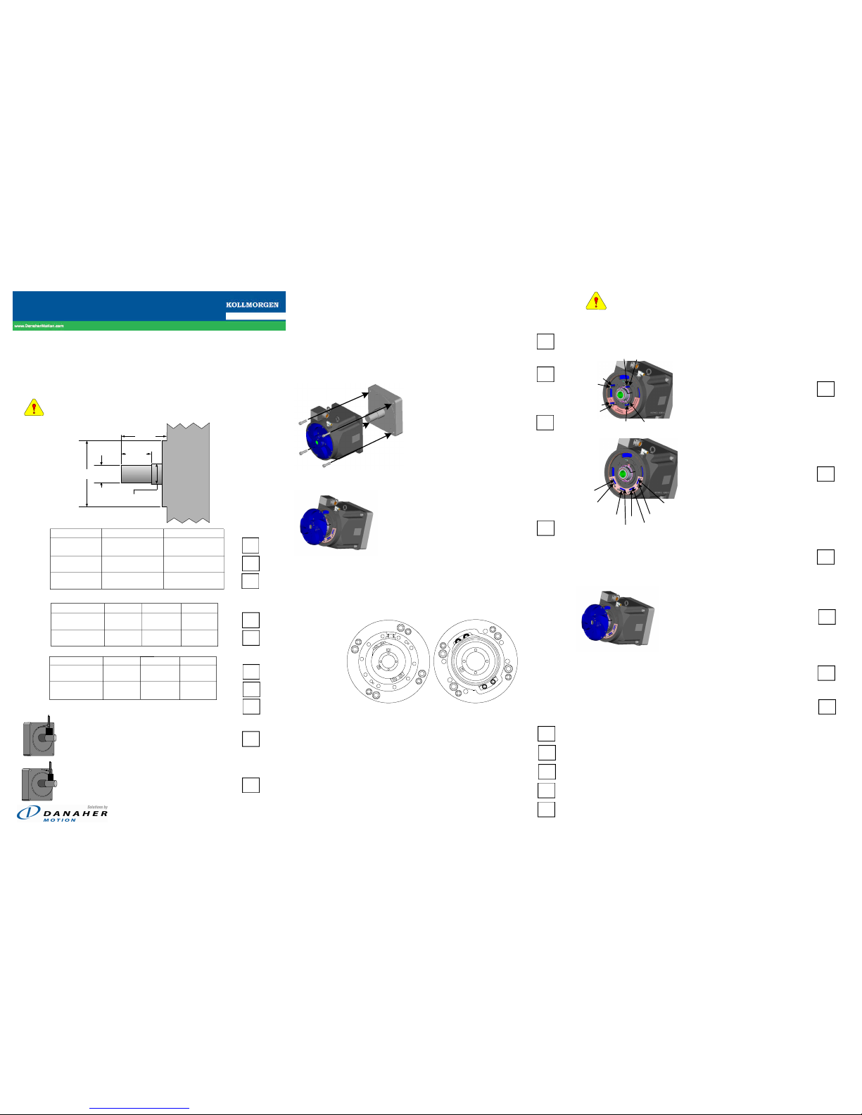
Step 1 Check Machine Mounting Dimensions
Incorrect mounting dimensions can damage Motor and/or
Machine.
Check Here
Diameter C(H)09X C(H)13X
Pilot 9.170 - 9.172 13.147 - 13.149
[232.92 - 232.96] [333.94 - 333.98]
Large Shaft 2.7554 - 2.7559 3.1491 - 3.1496
[69.988 - 69.999] [79.988 - 79.999]
Small Shaft 2.3617 - 2.3622 2.7554 - 2.7559
[59.988 - 59.999] [69.988 - 69.999]
Shaft Length C(H)091 C(H)092 C(H)093
Small 1.730 3.470 4.910
± 0.005 [0.13] [43.94] [88.14] [124.71]
Overall 3.540 5.280 6.720
± 0.06 [1.5] [89.92] [134.11] [170.69]
Shaft Length C(H)131 C(H)132 C(H)133
Small 1.590 3.300 4.670
± 0.005 [0.13] [40.39] [83.82] [118.62]
Overall 4.490 6.610 9.980
± 0.06 [1.5] [114.05] [167.89] [253.49]
With a dial indicator measure shaft runout.
0.038 mm (0.0015 in) TIR
With a dial indicator mounted to the shaft, measure Pilot Concentricity.
0.05mm (0.002 in) TIR
With a dial indicator mounted to the shaft, measure Mounting Surface
Perpendicularity.
0.05 mm (0.002 in) TIR
Step 2 Secure Motor to Machine Frame
Check Here
Wipe down shaft and motor's rotor hub bore. Light
oil residue is acceptable, but remove grease and
other contaminates.
Insert the provided key into the keyway in the shaft
with the point toward the end of the shaft.
Slide motor onto the shaft. Secure
the motor to machine frame using
four (4) bolts (not included).
Step 3 Remove End Cover
Using a Phillips screw driver, remove the
blue end cover by loosening the pan
head screws (eight (8) on the C(H)09 and
twelve (12) on the C(H)13.
Step 4 Tighten Compression Coupling
Access compression coupling bolts through holes labeled "A".
Use 6 mm hex bit attached to a torque wrench. There are (6)
compression coupling bolts on C(H)09 motor and (10) on the
C(H)13.
Hand tighten each bolt in a circular pattern to approximately
0.1 N-m (1 lb-in.).
Tighten each bolt in a circular pattern, twice around to 13 N-m
(10 lb-ft).
Retighten each bolt in a circular pattern, twice around to
20 N-m (15 lb-ft).
Retighten each bolt in a circular pattern, twice around to
30 N-m (22 lb-ft).
Go around, tightening each bolt to 30 N-m (22 lb-ft) until no
bolt moves (may take up to 8 complete revolutions).
Properly torque the compression coupling to avoid
significant damage to the motor and the machine to
which it is mounted.
Step 5
Remove and Secure Shipping Hardware
Check Here
Remove (4) shipping bolts "B"
and (4) set screws "C" using
6 mm hex wrench.
Place shipping bolts and set
screws into foam holder.
Step 6 Confirm Free Rotation
Rotate load by hand to insure free movement.
Step 7 Replace End Cover
Ensure the O-ring on the outside
of the end cover is in place.
Rotate the end cover until the alignment mark
matches the corresponding mark on the housing.
Secure the end cover by tightening the pan head
screws (eight (8) on the C(H)09 and twelve (12)
on the C(H)13).
Congratulations!
Your CARTRIDGE DDR
TM
motor is ready for operation.
CAUTION
Small Shaft
Diameter
Small
Shaft
Length
Large Shaft Diameter
Overall
Shaft
Length
Pilot
Diameter
Customer’s
Machine
A
A
A
A
A
A
A
A
A
A
B
B
B
B
C
C
C
C
C13
C09
A
A
A
A
A
A
B
B
B
B
C
C
C
C
CAUTION
BOLT
BOLT
BOLT
BOLT
SCREW
SCREW
SCREW
SCREW
BOLT
BOLT
BOLT
BOLT
SCREW
SCREW
SCREW
SCREW
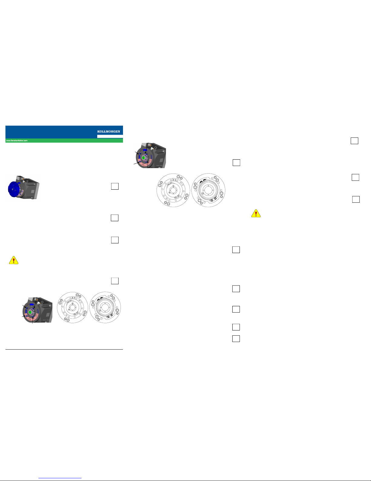
CARTRIDGE DDR
TM
Motor Removal Instructions
Step 1 Remove End Cover Check Here
Using a Phillips screw driver, remove
the blue end cover by loosening the pan
head screws (8 screws on the C(H)09
and (12) screws on the C(H)13).
Step 2 Align Rotor
Turn Motor shaft by hand until the index mark
on the rotor and stator of the encoder line up
together.
Use a flashlight to look into the holes labeled
"B". Turn the Motor shaft by hand until there is
a threaded hole directly behind each of the
four holes labeled "B".
Step 3 Install Set Screws
Do not use any type of Loctite or thread lock
on the shipping hardware.
Remove the (4) set screws from the foam holder
and thread them onto the holes labeled "C". Using
a 6 mm hex driver on a torque wrench, tighten each
set screw to 0.1 N-m (1 lb-in).
M-RT-019-07 Rev A May 14, 2004
Step 4 Install Shipping Bolts Check Here
Remove the (4) shipping bolts from
the foam holder and thread them
into the holes labeled "B". Using a
6 mm hex driver on a torque wrench,
tighten each shipping bolt to
16 N-m (12 lb-ft).
Step 5 Loosen Compression Coupling Bolts
Using a 6 mm hex driver, loosen the compression
coupling bolts through the holes labeled "A". There
are six (6) compression coupling bolts on the C(H)09
motor and ten (10) on the C(H)13. Loosen the bolts
in a circular pattern. Loosen 2 revolutions past the
point where the bolts are finger tight. Check each
bolt a second time to insure it is loose.
Step 6 Release Compression Coupling
Insert the 6 mm hex driver into one of the
compression coupling bolt holes labeled "A" and
seat it into the head of the bolt. Lightly tap it with
a hammer to release the compression coupling.
Repeat this step with another compression coupling
bolt exactly opposite the one just tapped.
On C(H)133 models only, to release the rear
compression coupling, insert a M6 x 1 x 120 screw
or threaded rod into the holes labeled "D" and
tighten until the part breaks loose.
Step 7 Replace End Cover
Ensure the O-ring on the outside of the end cover
is in place.
Rotate the end cover until the alignment mark
matches the corresponding mark on the housing.
Check Here
Secure the end cover by tightening the pan head
screws (eight (8) on the C(H)09 and twelve (12)
on the C(H)13).
Step 8 Remove Motor From Machine
Remove the (4) mounting bolts securing the
motor frame to the machine and slide the motor
off the shaft. The threaded holes (M10 on
C(H)09x or M12 on C(H)13x) beside the mounting
holes are provided for jacking purposes, if
necessary.
Step 9 Cover Mounting End
Secure a cardboard cover to the open mounting
end of the motor.
The mounting end of the motor is magnetized
and will attract magnetic material. This end of
the motor must be covered to insure proper
cleanliness.
Customer Support
Danaher Motion products are available worldwide through an extensive
authorized distributor network. These distributors offer literature, technical
assistance, and a wide range of models off the shelf for the fastest possible
delivery.
Danaher Motion sales engineers are conveniently located to provide
prompt attention to customer needs. Call the nearest office for ordering and
application information or for the address of the closest authorized distributor. If you do not know who your sales representative is, contact us:
203A Rock Road
Radford, VA 24141
Phone: 540-633-3400
Fax: 540-639-4162
Email: customer.support@danahermotion.com
Web: www.DanaherMotion.com
Danaher Motion® is a registered trademark of the Danaher
corporation. Danaher Motion makes every attempt to ensure accuracy
and reliability of the specifications in this publication. Specifications
are subject to change without notice. Danaher Motion provides this
information "AS IS" and disclaims all warranties, express or implied,
including, but not limited to, implied warranties of merchantability and
fitness for a particular purpose. It is the responsibility of the product
user to determine the suitability of this product for a specific
application.
© 2004, Danaher Motion - All rights reserved.
Printed in the United States of America.
Through
Bore
Motors
Solid
Shaft
Motors
A
A
A
A
A
A
A
A
A
A
B
B
B
B
C
C
C
C
C13
C09
A
A
A
A
A
A
B
B
B
B
C
C
C
C
CAUTION
A
A
A
A
A
A
A
A
A
A
B
B
B
B
C
C
C
C
C13
C09
A
A
A
A
A
A
B
B
B
B
C
C
C
C
CAUTION
INSTALL
SCREW
INSTALL
SCREW
INSTALL
SCREW
INSTALL
SCREW
INSTALL
BOLT
INSTALL
BOLT
INSTALL
BOLT
INSTALL
BOLT
 Loading...