

Koldfront WTC10002WCO115V, WTC12002WCO115V, WTC10012WCO230V, WTC12012WCO230V, WTC12001W Service Manual
...Page 1

EdgeStar, 8606 Wall St, Suite 1800, Austin, TX 78754
support.edgestar.com • service@edgestar.com • edgestar.com
*Warranty service should be performed by an authorized service representative only.
SERVICE MANUAL
Koldfront Through the Wall Air Conditioner
MODELS COVERED:
WTC8001W
WTC12001W
WTC8002WCO
WTC10002WCO115V
WTC10012WCO230V
WTC12002WCO115V
WTC12012WCO230V
WTC14012WCO230V
Document Type: Service Manual
Version: V1.0 04112018
CAUTION: READ ALL SAFETY PRECAUTIONS IN THIS
MANUAL BEFORE SERVICING THE UNIT
Page 2

1
CONTENTS
CONTENTS ....................................................................................................................................... 1
SAFETY PRECAUTIONS ..................................................................................................................... 2
ELECTRICAL SAFETY ..................................................................................................................... 3
GENERAL SAFETY ......................................................................................................................... 4
1 EXPLODED DIAGRAMS AND PART LISTS ...................................................................................... 5
1.1 WTC8001W AND WTC12001W ............................................................................................. 5
1.2 WTC WCO MODELS ............................................................................................................... 7
1.3 DIMENSIONS ......................................................................................................................... 9
2 WIRING DIAGRAM (ALL MODELS) .............................................................................................. 10
3 MAIN COMPONENTS.................................................................................................................. 11
3.1 MAJOR PARTS ..................................................................................................................... 11
3.2 ELECTRONIC CONTROL BOX AND MAIN PCB ...................................................................... 11
4 UNIT OPERATION ....................................................................................................................... 12
4.1 DISPLAY PANEL CONTROLS ................................................................................................. 12
4.2 REMOTE CONTROL .............................................................................................................. 14
5 INSTALLATION AND CLEANING .................................................................................................. 15
5.1 PROPER INSTALLATION AND DRAINAGE............................................................................. 15
5.2 CLEANING THE FILTER ......................................................................................................... 16
6 MODES AND OPERATING CONDITIONS ..................................................................................... 17
6.1 TERMS AND DEFINITIONS ................................................................................................... 17
6.2 PROTECTION FUNCTIONS ................................................................................................... 17
6.3 AUTO MODE ........................................................................................................................ 17
6.4 FAN-ONLY MODE ................................................................................................................ 17
6.5 COOLING MODE .................................................................................................................. 18
6.6 AUTO-DEFROST FUNCTION ................................................................................................. 18
6.7 DRY MODE ........................................................................................................................... 19
6.8 SLEEP MODE ........................................................................................................................ 19
7 TROUBLESHOOTING ................................................................................................................... 20
7.1 TROUBLESHOOTING GUIDE ................................................................................................ 20
7.2 ERROR CODES AND SENSOR MALFUNCTIONS .................................................................... 21
7.3 TEMPERATURE SENSOR RESISTANCE TEST TABLE .............................................................. 22
Page 3

2
SAFETY PRECAUTIONS
WARNING: This manual and the information contained herein is intended for use
by certified technicians. The manufacturer or seller is not responsible for the
interpretation or misuse of the information provided, nor does it assume any
liability in connection with its use.
The safeguards and warnings indicated in this manual do not cover all possible
conditions which may occur. Common sense, caution, and care must be
exercised.
To prevent electric shock, always unplug an appliance from the power supply before attempting
any service.
Disconnect the power cord by grasping the plug, not the cord.
Do not bypass, cut, or remove the grounding plug.
Prevent water from spilling onto electric elements or the machine parts.
Always refer to the rating label on the appliance for rated current and voltage.
Always check line voltage and amperage.
Always use exact replacement parts.
Any attempt to repair a major appliance may result in personal injury and property damage.
Page 4
3
Electrical Safety
Do not exceed the power outlet ratings.
It is recommended that the unit be connected to its own circuit.
A standard electrical supply that is properly grounded in accordance with the National Electrical Code
and all state and local codes and ordinances is required.
Do not use outlets that can be turned off by a switch or pull chain.
Always turn the unit off and unplug it from the outlet when cleaning.
Unplug the unit if it is not going to be used for an extended period of time.
Do not operate the unit with a power plug missing the ground plug, a damaged cord, or a loose socket.
Be sure the appliance is properly grounded.
Do not bypass, cut, or remove the grounding plug.
If the power cord is damaged, it must be replaced by the manufacturer or a qualified technician.
Do not use extension cords or power strips with this unit. You may need to contact an electrician if it is
necessary to use a longer cord or if you do not have a properly grounded outlet. Do not modify the
power cord’s length or share the outlet with other appliances.
Do not start or stop the unit by switching the electrical circuit’s power on and off.
Immediately unplug the unit if it makes strange sounds, emits an odor or smoke and contact customer
service.
Do not remove any part of the casing unless instructed by an authorized technician.
Before the appliance is removed from service or discarded, remove any doors and cut off the power
cord.
Page 5

4
General Safety
Always unplug an appliance from the power supply before attempting any service. Disconnect the
power cord by grasping the plug, not the cord.
Do not allow children or pets to play on or in the appliance.
This machine is not intended for use by persons (including children) with reduced physical, sensory or
mental capabilities, or lack of experience and knowledge, unless they have been given supervision or
instruction concerning use of the machine by a person responsible for their safety.
Do not install or store this appliance where it will be exposed to the weather.
Disconnect from the power socket before cleaning or maintenance.
If the plug (power cord) is damaged, it must be replaced by the manufacturer or an authorized service
representative.
This machine shall be repaired only by an authorized service representative. Only genuine
replacement parts should be used.
If connected to a circuit protected by fuses, use time-delay fuses with this appliance.
Do not lean items against the glass door.
Please do not close the door with excessive force. If it is found difficult to close the door, please check
for obstruction.
When you plan to dispose of this unit in the future, please comply with the local waste disposal
regulations. Remove any doors so that children and pets will not be trapped in the unit.
Page 6
5
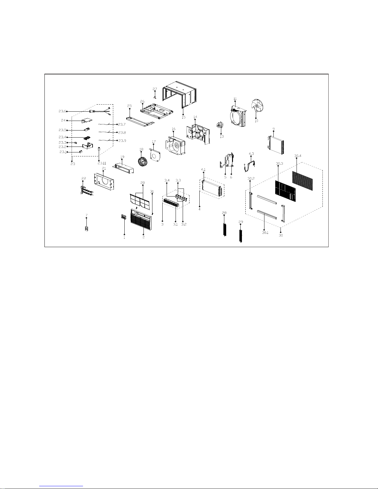
1 Exploded Diagrams and Part Lists
1.1 WTC8001W and WTC12001W
Page 7
6
No.
Part Name
No.
Part Name
1
Display assembly
22
Electric heater
2
Front panel
23
Electronic control box assembly
3
Air outlet assembly
23.1
Capacitor for fan motor
3.1
Air outlet
23.2
Electronic control box
3.2
Horizontal louver
23.3
Transformer
3.3
Connecting rod for louver
23.4
Bracket for main control board
3.4
Horizontal louver
23.5
Main control board assembly
4
Evaporator coil assembly
23.6
Power cord
4.1
Evaporator
23.7
Defrost sensor assembly
4.3
Capillary tube assembly
23.8
Ambient temperature sensor assembly
5
Discharge pipe assembly
23.9
Heater temperature sensor assembly
6
Compressor
23.11
Capacitor for compressor
7
Remote control
24
Cover for electronic control box
9
Condenser
25
Condenser water tray
10
Axial flow fan
26
Chassis assembly
11
Rear separating housing
27
Drain valve
13
Fan motor
28
Grille
14
Front separating housing
29
Grille
15
Cabinet
30
Installation accessories
16
Rear volute shell
30.1
Upper and lower shutter frame
17
Heat insulation
30.2
Left and right shutter frame
18
Centrifugal fan
30.3
Rear grille
19
Front volute shell
30.4
Plastic net
20
Air filter
31
Filter guide
21
Box for electric heater
Page 8
7
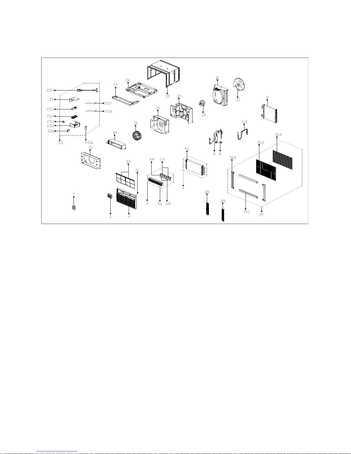
1.2 WTC WCO Models
Page 9

8
No.
Part Name
No.
Part Name
1
Display assembly
21
Electrical heating box (for units with heat)
2
Front panel
23
Electronic control box assembly
3
Air outlet assembly
23.1
Capacitor
3.1
Air outlet
23.2
Electrical control box
3.2
Horizontal louver
23.3
Transformer
3.3
Connecting rod for louver
23.4
Mounting rack for main control panel
3.4
Horizontal louver
23.5
Main control board
4
Evaporator assembly
23.6
Power supply cord
4.1
Evaporator
23.7
Defrost temperature sensor
4.3
Capillary tube assembly
23.8
Room temperature sensor
5
Compressor exhaust pipe assembly
23.11
Compressor capacitor
6
Compressor
24
Electrical control box cover
7
Remote control
25
Water receiver tray
9
Condenser
26
Chassis assembly
10
Axial fan
28
Rear grill
11
Rear barrier assembly
28
Rear grill
13
Fan motor
30
Installation accessories
14
Front barrier assembly
30.1
Upper and lower shutter frame
15
Cabinet
30.2
Left and right shutter frame
16
Rear air duct foam
30.3
Air inlet grille
18
Centrifugal fan
30.4
Plastic Rear Guard
19
Front air duct foam
31
Filter guide
20
Air filter
Page 10

9
1.3 Dimensions
Width
Height
Depth
WTC UNIT
24-1/4” (615 mm)
14-1/2” (369 mm)
20-1/4” (515 mm)
WTC SLEEVE
25-5/8” (649 mm)
15-1/4” (388 mm)
17-1/2” (445 mm)
Wall Sleeve
Model: WTCSLV
WTC Wall Unit
Page 11

10
2 Wiring Diagram (All Models)
Note:
This wiring diagram is for illustration purposes only. The actual shapes of components may be different.
@ indicates optional components that are not included in all models.
Page 12

11
3 Main Components
3.1 Major Parts
3.2 Electronic Control Box and Main PCB
4 Operating Instructions
4.1 Display Panel Controls
Page 13

12
4 Unit Operation
4.1 Display Panel Controls
On-Off Button
Press to turn on or off the unit.
NOTE: The Energy Saver feature will automatically turn on in Cool, Dry, and Auto mode.
Up and Down Button
Press or hold either Up or Down button until desired temperature is seen on the digital
display. This temperature will be automatically maintained anywhere between 62 °F (17° C) and 86° F
(30° C). Pressing and holding both Up and Down buttons for 3 seconds, will change the display from ℉ to
℃.
Mode select Button
To choose the operating mode press Mode . Each time you press the button a mode is selected in a
sequence that goes from Auto, Cool, Dry, to Fan. The indicator light beside the mode button will be
illuminated and remain on once the mode is selected.
NOTE: The unit will automatically turn on the Energy Saver function under Cool, Dry, and Auto.
Page 14

13
Fan speed Button
To select the speed of the fan press Fan Speed which cycles through four steps- Auto, Low,
Medium, or High. Each time the button is pressed the fan speed mode is shifted.
NOTE: The fan speed is automatically set to low and cannot be adjusted in Dry mode.
Energy Saver Button
To start the Energy Saver feature, press the Energy Saver button. This feature is available on Cool,
Dry, and Auto. The fan continues to run for 3 minutes after the compressor shuts off. The fan then cycles
on for 2 minutes at 10 minute intervals until the room temperature is above the set temperature, at which
point the compressor turns back on and cooling starts.
Timer Button
When the unit is on or off, press the Timer button and the “Timer On” indicator light illuminates. It
indicates that the Auto Start/Stop program is initiated.
To switch to off press the Timer button again and the “Timer Off” indicator light illuminates. It
indicates that the Auto Stop program is initiated.
Press or hold the Up or Down button to change the Auto Time by ½ hour increments up to
10 hours or 1 hour increments up to 24 hours. The control will count down the time remaining until
start.
The selected time will display for five (5) seconds and then will automatically revert back to display
the previous temperature setting or room temperature when the unit is on.
Turning the unit ON or OFF at any time or adjusting the timer setting to 0.0 will cancel the Auto
Start/Stop program.
The timer is not a permanent setting. The user must set the timer each they wish to use it.
Sleep Button
To initiate, press the Sleep button. In this mode the selected temperature will increase by 2°F (1°C)
30 minutes after the mode is selected. The temperature will then increase by another 2°F (1°C) after an
additional 30 minutes. This new temperature will be maintained for 6 hours before it returns to the
originally selected temperature. This ends the Sleep mode and the unit will continue to operate as
originally programmed. The Sleep Mode program can be cancelled at any time during operation by again
pressing the Sleep button.
Check Filter Button
This feature is a reminder to clean the Air Filter for more efficient operation. The LED light will illuminate
after 250 hours of operation. To reset after cleaning the filter, simply press the Check Filter button
and the light will go off.
Page 15

14
4.2 Remote Control
The remote control has an operating range of 16 ft. from the appliance.
The remote signal receiver/sensor is located on the control panel of the air conditioner.
Reception of signal commands is confirmed by an audible beep.
Direct sunlight can interfere with the infrared signal.
To replace batteries, remove the back cover by pressing where indicated and sliding off the battery
cover.
Page 16

15
5 Installation and Cleaning
5.1 Proper Installation and Drainage
Older Koldfront window air conditioners included a drain plug that could be removed to assist with water
drainage in excessively humid operating environments. Current models DO NOT use drain plugs. WAC
series air conditioners were modified to increase unit operating efficiency and as a result the drain hole
and plug have been removed.
As water builds up towards the rear / back of the unit the fan blade will begin to splash and disperse that
water over the condenser coils which significantly aids in cooling the internal components and increases
the overall efficiency of the unit. If there is an over-accumulation of water, it will simply drain out of the
lower back edge of the unit onto the exterior ground. Provided that the unit has been installed properly
with a slight rearward slope as indicated below, there will not be drainage issues with the unit.
Service Note: Check that the air conditioner is tilted about 3° to 4° (degrees) downward slope toward the
outside. After proper installation, water from the coils should not drain from the unit during normal use.
Correct the slope if necessary.
Page 17

16
5.2 Cleaning the Filter
In order to maintain energy efficiency and prolong the life of the unit the air filter should be checked at
least once a month to see if cleaning is necessary. In addition, trapped particles in the filter can quickly
build up and cause frost on the evaporator.
1. Open the front panel.
2. Take the filter by the center and pull up and out.
3. Wash the filter using liquid dishwashing detergent and warm water. Rinse filter thoroughly. Gently
shake excess water from the filter. Be sure the filter is thoroughly dry before replacing.
4. You may also gently use a vacuum to clean the filter.
5. Reinstall the air filter once it’s clean and dry.
Service Note:
1. Never use hot water over 104℉(40℃) to clean the air filter.
2. Never attempt to operate the unit without the air filter.
3. The air filter should be checked at least once a month to see if cleaning is necessary.
4. When the check filter light comes on clean the filter. It will be prolong the life of the unit and save
energy.
5. When the AC has not used for a for a prolonged period of time clean the filter before re-use.
Page 18

17
6 Modes and Operating Conditions
6.1 Terms and Definitions
1. TA: Temperature of indoor ambient.
2. TE: Temperature of evaporator.
3. TS: The set temperature.
4. DAHT: Heater sensor.
6.2 Protection Functions
The compressor restart protection has a delay of 3 minutes.
5 minute operation for compressor in cooling mode.
Sensor protection against an open or short circuit.
6.3 Auto Mode
AUTO Mode is a setting that allows the unit to automatically switch between COOL and FAN in order
to achieve and maintain the desired set temperature.
In Auto mode the unit will choose cooling or fan-only mode based on ΔT(ΔT=TA-TS)
ΔT = TA - TS
Running mode
ΔT > 4F
Cooling
-2F ≤ ΔT ≤ 4F
Fan-only
The unit will default to running mode when in auto mode under the following circumstances:
1. Powering on, changing mode to auto mode or adjusting temperature in auto mode will cause the unit
to default to running mode again.
2. A: In auto mode, if the compressor does not run for 15 minutes check condition B.
3. B: If ΔT<-8℉ or ΔT >2℉, the unit will default to running mode again according to ΔT until the
compressor stops.
6.4 Fan-Only Mode
If the temperature can’t be controlled by the selected mode and the room ambient temperature is
shown on the display the unit will default to fan only mode.
The readout can only display a temperature of 32 to 99 ℉ (0 to 37℃.) lf the temperature is out of that
range the display will show LO or HI.
The Timer function works in fan-only mode.
The follow me function (on some models) does not work in fan-only mode.
Page 19

18
6.5 Cooling Mode
The cooling temperature can be set from 62 to 86℉ (17 to 30℃.)
Sleep, Timer and Energy Saver functions work in cooling mode.
The compressor will run when the difference between the set temperature and the actual ambient
room temperature conforms to the chart below:
1. When TA≤TS (for 1 minute) the compressor turns off.
2. When T1>TS+2℉ the compressor turns on.
6.6 Auto-Defrost Function
The Auto-defrost function operates according to the chart below:
1. When TE is below 30℉ the evaporator will frost. As the unit defrosts the indoor fan will continue to
operate.
2. When the temperature is up over 55℉ the unit will stop defrosting.
(TA-Ts)℉
+2
0
Operation conditon
compressor off with a delay of 1 minute
compressor on
TE ℉
55
30
compressor off
when TE is lower than 30℉
lasting for 5 seconds
compressor on
Page 20

19
6.7 Dry Mode
In this mode, the air conditioner will operate as a dehumidifier. Because the conditioned space is
closed or sealed, some degree of cooling will continue to occur.
The dry mode temperature can be set from 62 to 86℉ (17 to 30℃.)
The fan speed is Low and can’t be controlled.
Sleep function works in dry mode.
6.8 Sleep Mode
This mode has a duration of 7 hours and can be used in Cool, Dry and Heat mode.
In sleep mode the fan speed will default to Auto.
In the first 60 minutes, the set temp will rise (or lower for heating mode) 2℉ (1℃) each half hour.
Then it will keep a steady temperature for 6 hours until the mode stops.
If you change any settings after sleep mode starts, the function will stop. Press sleep button again or
use the remote control to start it again.
Page 21

20
7 Troubleshooting
7.1 Troubleshooting Guide
Problem
Possible Cause
Solution
Air conditioner does
not function at all.
Wall plug is disconnected.
Insert plug firmly into proper wall outlet.
House fuse blown or circuit
breaker tripped.
Replace fuse with time delay type or reset
circuit breaker.
Power cord is tripped.
Press the RESET button on the power cord.
Unit is turned OFF.
Turn unit ON and set to desired setting.
Ribbon cable to control panel is
disconnected.
Remove front grill and reconnect cable.
Loose or disconnected wiring
on main PCB.
Remove front grill and outer shell. Check all
connections to the PCB and reconnect any
loose or disconnected leads.
Air from unit does
not feel cold
enough.
Room temperature is below
62℉ (17℃).
Cooling will not occur until room temperature
rises above 62℉ (17℃).
Temperature sensor behind the
front grill and air filter is
touching the cold evaporator.
Realign sensor so it does not touch the
evaporator coil. It should only be sensing the
air temperature leaving the evaporator.
Set temperature is too high.
Set to a Lower temperature.
Compressor is shut-off by
changing modes.
Wait approximately 3 minutes and listen for
compressor to restart when set in COOL
mode.
Air conditioner
cooling, but room is
too warm - ice
forming on cooling
coil behind front grill.
Outdoor temperature below
62℉ (17℃).
To defrost the coil, set to FAN ONLY mode.
Air filter may be dirty.
Clean filter. Refer to Installation and Cleaning
section. To defrost, set to FAN ONLY mode.
Thermostat set too cold for
night-time cooling.
To defrost the coil, set to FAN ONLY mode.
Then set temperature to a Higher setting.
Air conditioner
cooling, but room is
too warm - NO ice
forming on cooling
coil behind front grill.
Dirty air filter- air restricted.
Clean air filter. Refer to Installation and
Cleaning section.
Temperature is set too High.
Set to a Lower temperature.
The directional louvers on the
front are positioned improperly.
Position louvers for better air distribution.
Page 22

21
Front of unit is blocked by
drapes, blinds, furniture, etc.
and is restricting air distribution.
Clear blockage in front of unit.
Doors, windows, registers, etc.
are open and cold air is
escaping.
Close doors, windows, registers.
Unit recently turned on in hot
room.
Allow additional time for unit to remove stored
heat from walls, ceiling, floor and furniture.
Air conditioner turns
on and off
frequently.
Dirty air filter- air restricted.
Clean air filter.
Outside temperature is
extremely hot.
Set FAN speed to a Higher setting to push
more air through the coils.
Noise when unit is
cooling.
Air movement sound.
This is normal. If too loud, set to a slower FAN
setting.
Window vibration - poor
installation.
Refer to installation instructions or check with
installer.
Water dripping
INSIDE when unit is
cooling.
Improper installation.
Tilt air conditioner slightly downward toward
the outside to allow water drainage. Refer to
installation instructions - check with installer.
Water dripping
OUTSIDE when unit
is cooling.
Unit removing large quantity of
moisture from humid room.
This is normal during very humid days.
Room too cold
Set temperature is too low.
Increase the set temperature.
7.2 Error Codes and Sensor Malfunctions
If display indicates an AS error, use the mode button to select "Fan" and LO or HI will be
displayed to indicate the underlying condition. See section 7.3 for additional information.
Display
Error
Solution
AS
Room temperature sensor error.*
Check sensor connection to main PCB and
secure any detached or loose connections.
Check sensor wire for damage and repair if
possible.
Test sensor (see table 7.3) Replace sensor if
defective.
LO
Room sensor is an open circuit.*
HI
Room sensor is a short circuit.*
●
Defrost sensor is open or short
circuit.
Page 23

22
7.3 Temperature Sensor Resistance Test Table
Temp.
℃
Temp.
℉
Resistance
KΩ
Temp.
℃
Temp.
℉
Resistance
KΩ
Temp.
℃
Temp.
℉
Resistance
KΩ
-10
14
62.2756
17
62.6
14.6181
44
111.2
4.3874
-9
15.8
58.7079
18
64.4
13.918
45
113
4.2126
-8
17.6
56.3694
19
66.2
13.2631
46
114.8
4.0459
-7
19.4
52.2438
20
68
12.6431
47
116.6
3.8867
-6
21.2
49.3161
21
69.8
12.0561
48
118.4
3.7348
-5
23
46.5725
22
71.6
11.5
49
120.2
3.5896
-4
24.8
44
23
73.4
10.9731
50
122
3.451
-3
26.6
41.5878
24
75.2
10.4736
51
123.8
3.3185
-2
28.4
39.8239
25
77
10
52
125.6
3.1918
-1
30.2
37.1988
26
78.8
9.5507
53
127.4
3.0707
0
32
35.2024
27
80.6
9.1245
54
129.2
2.959
1
33.8
33.3269
28
82.4
8.7198
55
131
2.8442
2
35.6
31.5635
29
84.2
8.3357
56
132.8
2.7382
3
37.4
29.9058
30
86
7.9708
57
134.6
2.6368
4
39.2
28.3459
31
87.8
7.6241
58
136.4
2.5397
5
41
26.8778
32
89.6
7.2946
59
138.2
2.4468
6
42.8
25.4954
33
91.4
6.9814
60
140
2.3577
7
44.6
24.1932
34
93.2
6.6835
61
141.8
2.2725
8
46.4
22.5662
35
95
6.4002
62
143.6
2.1907
9
48.2
21.8094
36
96.8
6.1306
63
145.4
2.1124
10
50
20.7184
37
98.6
5.8736
64
147.2
2.0373
11
51.8
19.6891
38
100.4
5.6296
65
149
1.9653
12
53.6
18.7177
39
102.2
5.3969
66
150.8
1.8963
13
55.4
17.8005
40
104
5.1752
67
152.6
1.83
14
57.2
16.9341
41
105.8
4.9639
68
154.4
1.7665
15
59
16.1156
42
107.6
4.7625
69
156.2
1.7055
16
60.8
15.3418
43
109.4
4.5705
70
158
1.6469
Page 24

EdgeStar, 8606 Wall St, Suite 1800, Austin, TX 78754
support.edgestar.com • service@edgestar.com • edgestar.com
*Warranty service should be performed by an authorized service representative only.
DATE
REVISION NOTES
04/11/2018
INITIAL DOCUMENT
 Loading...