

Kohler PA-320751, PA-320743, PA-320742, PA-320748, PA-320747 Operation And Installation Instructions Manual
...Page 1

Operation and
Installation Instructions
Automatic Battery Chargers
Kits:
PA-320741
P
A-320741-SD through P
through P
A-320764 and
A-320764-SD
TT-855 12/93b
Page 2

Table of Contents
SUBJECT PAGE SUBJECT PAGE
Safety Precautions and Instructions 1.
Introduction 4
Specifications 5
Installing Charger 8.
Mount Charger 9.
Ouput Connections 9.
Input Connections 9.
Disconnecting Charger 11.
Battery Charger Operation 12.
Charging Lead-Acid Batteries 12.
Checking Specific Gravity 14.
Charging Nickel-Cadmium Batteries 14.
. . . . . . . . . . . . . . . . . . . . . . . . . . . . . . . . .
. . . . . . . . . . . . . . . . . . . . . . . . . . . . . . .
. . . . . . . . . . . . . . . . . . . . . . . . . . .
. . . . . . . . . . . . . . . . . . . . . . . . . . . . .
. . . . . . . . . . . . . . . . . . . . . . . . .
. . . . . . . . . . . . . . . . . . . . . . . . . .
. . . . . . . . . . . . . . . . . . . . .
. . . . . . . . . . . . . . . . . .
. . . . . . . . . . . . . . .
. . . . . . . . . . . . . . . . . .
. . . . . . . . . .
. . . . . . . . .
Charger Voltage Adjustment 15.
Charger and Battery Maintenance 15.
Troubleshooting 16
Standard Accessories 17.
Current Limiting 17.
Reverse Polarity Protection 17.
Automatic Float Operation 17.
Temperature Compensation 17.
AC Input Fuse 17.
DC Output Fuse 17.
Power On Lamp 17.
Wiring Diagrams 18.
Parts Lists 24.
. . . . . . . . . . . . . . . . . . . . . . . . . . . .
. . . . . . . . . . . . . . . . . . . . . .
. . . . . . . . . . . . . . . . . . . . . . . . . . .
. . . . . . . . . . . . . . . . . . . . . . . . . . . .
. . . . . . . . . . . . . . . . . . . . . . . . . .
. . . . . . . . . . . . . . . . . . . . . . . . . .
. . . . . . . . . . . . . . . . . . . . . . . . . . .
. . . . . . . . . . . . . . . . . . . . . . . . . . . . . . . . .
. . . . . . . . . . . . . . . .
. . . . . . . . . . .
. . . . . . . . . . . . . . . . .
. . . . . . . . . . . . . . . . . .
. . . . . . . . . . . . . . . .
-855 12/93
T
able of Contents
iTT
Page 3

Safety Precautions and Instructions
A generator set, like any other electro-mechanical
device, can pose potential dangers to life and limb if
improperly maintained or imprudently operated. The
best way to prevent accidents is to be aware of the
potential dangers and to always use good common
sense. In the interest of safety, some general
precautions
follow. Keep these in mind. This manual contains
several
below.
relating the to operating of a generator set
types of safety precautions
which are explained
CAUTION
Caution
will
damage if the warning is ignored.
Note
maintenance information that is important but not
hazard-related.
is
used to indicate the presence of a hazard that
or
can
is used
cause
to notify people of installation, operation, or
minor
personal injury or property
NOTE
DANGER
Danger is used to indicate the presence of a hazard that
will
cause
property damage if the warning is ignored.
Warning is used to indicate the presence of a hazard
that
substantial property damage if the warning is ignored.
severe
WARNING
can
cause
personal injury, death, or substantial
severe
personal injury, death, or
Accidental Starting
WARNING
Accidental starting.
Can cause severe injury or death.
Disconnect battery cables before working on
generator set (negative lead first and reconnect it
last).
Safety decals are affixed to the generator set in
prominent places to advise the operator or service
technician of potentially hazardous situations. The
decals are reproduced here to improve operator
recognition and thereby increase decal effectiveness.
For
a further
the accompanying safety precautions. Before
operating or servicing the generator set, be sure you
understand the message of these decals. Replace
decals if missing or damaged.
Accidental starting can cause severe injury or
death. Turn generator master switch to OFF position,
disconnect power to battery charger, and remove
battery cables (remove negative lead first and
reconnect
on any equipment connected to generator. The
generator set can be started by automatic transfer
switch or remote start/stop switch unless these
precautions are followed.
explanation of decal information, reference
it last) to disable generator set before working
-855 12/93
Safety Precautions
1TT
Page 4

Hazardous Voltage/Electrical Shock
WARNING
Hazardous voltage.
Can cause severe injury or death.
Do not operate generator set without all guards
and electrical enclosures in place.
Hazardous voltage can cause severe injury or
death. De-energize both normal and emergency power
sources before proceeding. Move generator master
switch on controller to OFF position and disconnect
battery negative (–) before working on transfer switch!
Turn the transfer switch selector switch to the OFF
position.
Hazardous voltage can cause severe injury or
death. Keep everyone away from the set and take
precautions to prevent unqualified personnel from
tampering.
only by qualified technicians. Wiring should be
inspected at the recommended interval shown in the
service schedule—replace leads that are frayed or in
poor condition. Do not operate electrical equipment
when standing in water, on wet ground, or when your
hands are wet.
Have the set and electrical circuits serviced
Moving rotor.
Hazardous voltage can cause severe injury or
death. Electrical shock may occur if battery charger is
not properly grounded. Connect battery charger
enclosure
an alternative, run an equipment-grounding conductor
with circuit conductors and connect to
equipment-grounding terminal or lead on battery
charger. Battery charger installation should be
performed
comply with all local codes and ordinances.
to ground of a permanent wiring
as prescribed in equipment manual and must
system. As
(Applies to Optional Battery Charger.)
Hazardous voltage can cause severe injury or
death. Improper reconnection may damage charger
and
battery(ies), and
Installation must be done by a qualified electrician.
create an electrical shock hazard.
(Applies to Optional Battery Charger.)
Hazardous voltage can cause severe injury or
death. Short circuits can cause bodily injury and/or
equipment damage. Do not contact electrical
connections
made.
cause short circuits.
with tools or jewelry while adjustments are
Remove wristwatch, rings, and jewelry that can
2 TT
Safety Precautions
-855 12/93
Page 5

Battery
WARNING
Sulfuric acid in batteries.
Can cause severe injury or death.
Use protective goggles and clothes. Can cause
permanent
in clothing.
Sulfuric
death. Sulfuric acid in battery can cause permanent
damage to eyes, burn skin, and eat holes in clothing.
Always
around the battery. If battery electrolyte
the
eyes or
for
15 minutes with large quantities of clean water
case of eye contact, seek immediate medical aid. Never
add acid to a battery once
service.
electrolyte.
damage to eyes, burn skin, and eat holes
acid in batteries
wear splash-proof safety goggles when working
on skin, immediately flush the af
Doing so may result in
can cause severe injury or
is splashed in
fected area
. In
the
battery has been placed in
hazardous spattering of
the
Explosion can cause severe injury or death. Battery
gases
can cause an explosion. Do not smoke or permit
flame or spark to occur near a battery at any time,
particularly
terminals
sparks that could cause an explosion. Remove
wristwatch,
battery. Never connect negative (–) battery cable to
positive (+) connection terminal of starter solenoid. Do
not
test battery condition by shorting terminals together
or sparks could ignite battery gases or fuel vapors. Any
compartment containing batteries must be well
ventilated to prevent accumulation of explosive gases.
To avoid sparks, do not disturb battery charger
connections
turn charger off before disconnecting battery
connections. When disconnecting battery, remove
negative lead first and reconnect it last.
when it is being charged. A
with tools,
rings, and any other jewelry before handling
while battery is being charged and always
etc. to prevent burns and to prevent
void contacting
NOTES
NOTE
Charge only LEAD-ACID or NICKEL-CADMIUM
batteries with battery charger.
NOTE
Split lock washers may be supplied with some kits. If
split lock washers are supplied with kit, their use is
optional.
(use with kits only)
NOTE
HARDWARE DAMAGE! Engine and generator may
make use of both American Standard and metric
hardware. Be sure to use the correct size tools to
prevent rounding of bolt heads and nuts.
-855 12/93
Safety Precautions
3TT
Page 6

Introduction
This TT includes the following kits:
PA-320741 through P
PA-320741-SD through PA-320764-SD
This manual contains important safety and operating
instructions for automatic 2-amp battery chargers.
Before using the battery charger, read all instructions
and cautionary instructions on (1) battery charger, (2)
battery, and (3) product using battery. Keep these
instructions
The battery chargers are designed for various AC
voltage,
follows:
in mind when operating the battery charger
50- or 60-Hz input, and capable of charging as
A-320764 and
12-Volt Charger Lead-Acid Battery (6-cell)
24-Volt Charger Lead-Acid Battery (12-cell)
Determine input voltage and type of battery(ies) to be
charged. Make any necessary modifications before
using charger.
Grounding Instructions—Connect the battery
charger
or an equipment-grounding conductor with circuit
.
conductors and connect it to equipment-grounding
terminal or lead on battery charger. Connections to
battery charger should comply with all local codes and
ordinances.
to a
grounded, metal, permanent wiring system
4 TT
Introduction
-855 12/93
Page 7
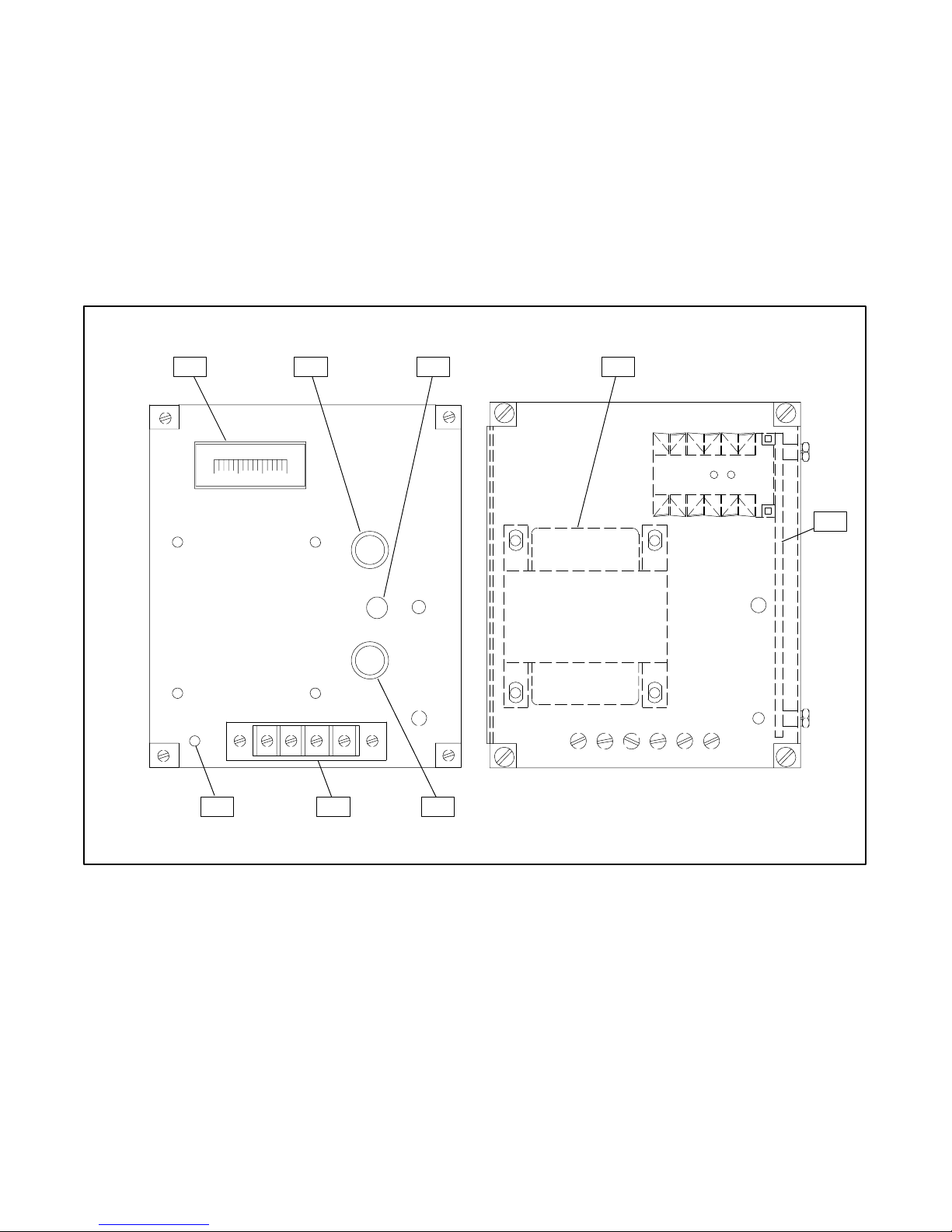
Specifications
The automatic battery charger is designed to charge
and maintain lead-acid and nickel-cadmium
automotive-type batteries in a fully charged state
without any manual intervention. The charger output
provided by the power transformer is controlled by the
circuit board. The control board provides the charger
with current-limiting, AC line compensation,
reverse-polarity protection, ambient-temperature
compensation, and constant voltage charging mode.
1 2 3 4
DC
AMPERES
0
AC INPUT
120V 50/60HZ .68A
DC OUTPUT
12V 2A
321
POWER
ON
DC
OUTPUT
6A
VOLT.
ADJ.
AC
INPUT
1A
The control circuit board continuously monitors the
battery and load conditions to maintain the battery’s
proper
state of charge. Refer to Figure 1 for component
identification. The chargers are factory adjusted to
maintain the battery at the proper float voltages. The
12-volt
charger will
maintain a lead-acid (6-cell) battery
with no adjustment required. The 24-volt charger will
maintain
a lead-acid (12-cell) battery with no adjustment
required.
5
294241-B
1. DC
Ammeter
2.
DC Output Fuse
3.
“Power On” Lamp
4. Transformer
GRD
AC
AC + –
678
5.
6.
7. T
8.
Figure 1. Battery Charger Components
Main Circuit Board Assembly
AC Input Fuse
erminal Block
Ground T
erminal (AC)
A-294226-A
P1
-855 12/93
Specifications
5TT
Page 8

Battery Charger Kits Selection Table
e
e
e
e
Volts Input Voltage
led
e
12 24
Descriptions
T
ransfer Switch Accessory No.
Battery Charger Kit No. *
T
ransfer Switch Accessory No.
Battery Charger Kit No. *
* SA
TS model transfer switches have an -SD suffix. EXAMPLE: P
Descriptions
T
ransfer Switch Accessory No.
Battery Charger Kit No. *
T
ransfer Switch Accessory No.
Battery Charger Kit No. *
* SA
TS+ model transfer switches have an -SD suf
Loos
Install
X X KA-24-62A KA-24-64A KA-24-63A KA-24-60A KA-24-68A KA-24-71A
X X PA-320741 PA-320747 PA-320745 PA-320751 PA-320743 PA-320749
X X KA-24-62B KA-24-64B KA-24-63B KA-24-60B KA-24-68B KA-24-71B
X X PA-320742 PA-320748 PA-320746 PA-320752 PA-320744 PA-320750
Figure 2. Battery Chargers for S340 Model Transfer Switch
Volts Input Voltage
led
e
Loos
12 24
Install
X X DA-24-62A DA-24-64A DA-24-63A DA-24-60A DA-24-68A DA-24-71A
X X PA-320741 PA-320747 PA-320745 PA-320751 PA-320743 PA-320749
X X DA-24-62B DA-24-64B DA-24-63B DA-24-60B DA-24-68B DA-24-71B
X X PA-320742 PA-320748 PA-320746 PA-320752 PA-320744 PA-320750
fix. EXAMPLE: P
120 V
50/60 Hz
120 V
50/60 Hz
240 V
50/60 Hz
A-320741-SD
240 V
50/60 Hz
A-320741-SD
220 V
50/60 Hz
220 V
50/60 Hz
480/600 V
50/60 Hz
480/600 V
50/60 Hz
208 V
50/60 Hz
208 V
50/60 Hz
380/416 V
50/60 Hz
380/416 V
50/60 Hz
Figure 3. Battery Chargers for S340+ Model Transfer Switch
Volts Input Voltage
led
e
Loos
12 24
Descriptions
T
ransfer Switch Accessory No.
Battery Charger Kit No. *
T
ransfer Switch Accessory No.
Battery Charger Kit No. *
* MA
TS model transfer switches have an -SD suffix. EXAMPLE: P
Install
X X KD-24-62A KD-24-64A KD-24-63A KD-24-60A KD-24-68A KD-24-71A
X X PA-320753 PA-320759 PA-320757 PA-320763 PA-320755 PA-320755
X X KD-24-62B KD-24-64B KD-24-63B KD-24-60B KD-24-68B KD-24-71B
X X PA-320754 PA-320760 PA-320758 PA-320764 PA-320756 PA-320756
Figure 4. Battery Chargers for M340 Model Transfer Switch
120 V
50/60 Hz
240 V
50/60 Hz
A-320741-SD
220 V
50/60 Hz
480/600 V
50/60 Hz
208 V
50/60 Hz
380/416 V
50/60 Hz
6 TT
Specifications
-855 12/93
Page 9

e
e
e
e
Descriptions
T
ransfer Switch Accessory No.
Battery Charger Kit No. *
T
ransfer Switch Accessory No.
Battery Charger Kit No. *
* MA
TS+ model transfer switches have an -SD suf
Loos
X X PA-320753 PA-320759 PA-320757 PA-320763 PA-320755 PA-320761
X X PA-320754 PA-320760 PA-320758 PA-320764 PA-320756 PA-320762
Figure 5. Battery Chargers for M340+ Model Transfer Switch
e
Descriptions
T
ransfer Switch Accessory No.
Battery Charger Kit No.
T
ransfer Switch Accessory No.
Battery Charger Kit No.
Loos
X X ––– ––– ––– ––– ––– –––
X X ––– ––– ––– ––– ––– –––
Figure 6. Battery Chargers for R33 Model Transfer Switch
Volts Input Voltage
led
12 24
Install
X X DD-24-62A DD-24-64A DD-24-63A DD-24-60A DD-24-68A DD-24-71A
X X DD-24-62B DD-24-64B DD-24-63B DD-24-60B DD-24-68B DD-24-71B
fix. EXAMPLE: P
Volts Input Voltage
led
12 24
Install
X X ––– KD-24-64A KD-24-63A ––– ––– –––
X X ––– KD-24-64B KD-24-63B ––– ––– –––
120 V
50/60 Hz
120 V
50/60 Hz
240 V
50/60 Hz
A-320741-SD
240 V
50/60 Hz
220 V
50/60 Hz
220 V
50/60 Hz
480/600 V
50/60 Hz
480/600 V
50/60 Hz
208 V
50/60 Hz
208 V
50/60 Hz
380/416 V
50/60 Hz
380/416 V
50/60 Hz
Descriptions
Primary Circuit
Protection
Secondary Circuit
Protection
Output Level
Preset at Factory
120 V
50/60 Hz
1 Amp 12 V
1.5 Amp 24 V
Figure 7. Battery Charger Specifications
240 V
50/60 Hz
0.5 Amp 12 V
1 Amp 24 V
12-V
olt Charger—13.2 V
24- V
olt Charger—26.4 V
Input Voltage
220 V
50/60 Hz
0.5 Amp 12 V
1 Amp 24 V
6 Amp Slo-Blo
480/600 V
50/60 Hz
0.2 Amp 12 V
0.4 Amp 24 V
208 V
50/60 Hz
0.5 Amp 12 V
1 Amp 24 V
olt, 2 Amp Current Limiting
olt, 2 Amp Current Limiting
380/416 V
50/60 Hz
0.3 Amp 12 V
0.5 Amp 24 V
-855 12/93
Specifications
7TT
Page 10

Installing Charger
WARNING
Sulfuric acid in batteries.
Can cause severe injury or death.
Use protective goggles and clothes. Can cause
permanent
in clothing.
damage to eyes, burn skin, and eat holes
NOTE
CHARGER
a battery with the same DC voltage as the battery
charger output rating.
DAMAGE!
Connect battery
charger only to
WARNING
Sulfuric
death. Sulfuric acid in battery can cause permanent
damage to eyes, burn skin, and eat holes in clothing.
Always
around the battery. If battery electrolyte
the
for
case of eye contact, seek immediate medical aid. Never
add acid to a battery once
service.
electrolyte.
Accidental starting.
Can cause severe injury or death.
Disconnect battery cables before working on
generator set (negative lead first and reconnect it
last).
Accidental starting can cause severe injury or
death. Turn generator master switch to OFF position,
disconnect power to battery charger, and remove
battery cables (remove negative lead first and
reconnect
on any equipment connected to generator. The
generator set can be started by automatic transfer
switch or remote start/stop switch unless these
precautions are followed.
acid in batteries
wear splash-proof safety goggles when working
eyes or
15 minutes with large quantities of clean water
on skin, immediately flush the af
Doing so may result in
WARNING
it last) to disable generator set before working
can cause severe injury or
is splashed in
fected area
. In
the
battery has been placed in
hazardous spattering of
the
Explosion.
Can cause severe injury or death. Relays in
battery charger cause arcs or sparks.
Locate in a well ventilated area. Keep explosive
fumes away.
Explosion
gases
flame or spark to occur near a battery at any time,
particularly
terminals
sparks that could cause an explosion. Remove
wristwatch,
battery. Never connect negative (–) battery cable to
positive (+) connection terminal of starter solenoid. Do
not
test battery condition by shorting terminals together
or sparks could ignite battery gases or fuel vapors. Any
compartment containing batteries must be well
ventilated to prevent accumulation of explosive gases.
To avoid sparks, do not disturb battery charger
connections
turn charger off before disconnecting battery
connections. When disconnecting battery, remove
negative lead first and reconnect it last.
can cause severe injury or death. Battery
can cause an explosion. Do not smoke or permit
when it is being charged. A
with tools,
rings, and any other jewelry before handling
while battery is being charged and always
etc. to prevent burns and to prevent
void contacting
8 TT
Installation
-855 12/93
Page 11

Mount Charger
1. Move generator master switch to OFF position.
Disconnect battery cables, negative lead first.
Open circuit breaker of AC power source to be
applied.
2. Turn automatic transfer switch selector to OFF
position.
3. Open automatic transfer switch enclosure.
Output Connections
NOTE
For
DC
connections use stranded copper wire, 600 V
105_C vinyl plastic insulation UL style 1015, CSA
TEW.
1. Due to the variety of generator installations,
battery cables are not provided. To make battery
connections, cut red (+) 10-gauge stranded wire
to proper length and strip insulation from both
ends. To one end of wire attach a post-type
connector. Route other end of battery cable and
connect
DC terminal block. See
block lock screw to secure battery cable. Repeat
to output positive (+) terminal on
Figure 8. T
ighten terminal
charger
olt,
type
4. Install four captive nuts (298811) in the transfer
switch
inner panel and install battery charger
Figure 8.
5. The battery charger is factory set to maintain the
proper
output for the battery voltage for which it is
rated. No customer adjustments are required.
procedure
connect black wire to output negative (–)
on DC terminal
2. Connect
terminal and black charger lead(s) to battery
negative (–) terminal.
Grounding Instructions—This
be connected to a grounded, metal, permanent wiring
system.
be run with circuit conductors and connected to
equipment-grounding terminal on battery charger.
Connections to battery charger should comply with all
local codes and ordinances.
An equipment-grounding conductor could
with black (–) 10-gauge stranded wire;
block
and secure with lock screw
red charger lead(s) to battery positive
battery charger should
. See
terminal
(+)
also
.
Input Connections
1. Connect
source as indicated by nameplate or transfer
switch wiring diagram.
the correct voltage, 50/60 Hz, AC power
2. Turn AC power on. Power On lamp will light and
ammeter will show charging current.
-855 12/93
Installation
9TT
Page 12
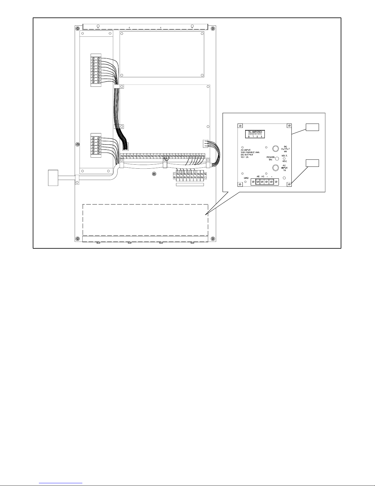
1. Battery
Charger Assembly (see parts lists)
Figure 8. Battery Charger Installation—Solid-State Transfer Switch
2.
Captive Nuts (29881
1) qty
1
2
BW-29500-B294241-B
. 4
10 TT
Installation
-855 12/93
Page 13

Disconnecting Charger
(When Replacing or Servicing Battery)
WARNING
Explosion.
Can cause severe injury or death. Relays in
battery charger cause arcs or sparks.
Locate in a well ventilated area. Keep explosive
fumes away.
Explosion
gases
flame or spark to occur near a battery at any time,
particularly
terminals
sparks that could cause an explosion. Remove
wristwatch,
battery. Never connect negative (–) battery cable to
positive (+) connection terminal of starter solenoid. Do
not
test battery condition by shorting terminals together
or sparks could ignite battery gases or fuel vapors. Any
compartment containing batteries must be well
ventilated to prevent accumulation of explosive gases.
To avoid sparks, do not disturb battery charger
connections
turn charger off before disconnecting battery
connections. When disconnecting battery, remove
negative lead first and reconnect it last.
can cause severe injury or death. Battery
can cause an explosion. Do not smoke or permit
when it is being charged. A
with tools,
rings, and any other jewelry before handling
while battery is being charged and always
etc. to prevent burns and to prevent
void contacting
Sulfuric
death. Sulfuric acid in battery can cause permanent
damage to eyes, burn skin, and eat holes in clothing.
Always
around the battery. If battery electrolyte
the
for
case of eye contact, seek immediate medical aid. Never
add acid to a battery once
service.
electrolyte.
Accidental starting.
Can cause severe injury or death.
Disconnect battery cables before working on
generator set (negative lead first and reconnect it
last).
Accidental starting can cause severe injury or
death. Turn generator master switch to OFF position,
disconnect power to battery charger, and remove
battery cables (remove negative lead first and
reconnect
on any equipment connected to generator. The
generator set can be started by automatic transfer
switch or remote start/stop switch unless these
precautions are followed.
acid in batteries
wear splash-proof safety goggles when working
eyes or
15 minutes with large quantities of clean water
on skin, immediately flush the af
Doing so may result in
WARNING
it last) to disable generator set before working
can cause severe injury or
is splashed in
fected area
. In
the
battery has been placed in
hazardous spattering of
the
WARNING
Sulfuric acid in batteries.
Can cause severe injury or death.
Use protective goggles and clothes. Can cause
permanent
in clothing.
-855 12/93
damage to eyes, burn skin, and eat holes
1. Move generator master switch to OFF position.
2. Remove AC power supply from battery charger.
3. Remove charger connectors from battery,
negative lead first.
Disconnection
11TT
Page 14

Battery Charger Operation
Charging Lead-Acid Batteries
WARNING
Sulfuric acid in batteries.
Can cause severe injury or death.
WARNING
Use protective goggles and clothes. Can cause
permanent
in clothing.
Sulfuric
death. Sulfuric acid in battery can cause permanent
damage to eyes, burn skin, and eat holes in clothing.
Always
around the battery. If battery electrolyte
the
eyes or
for
15 minutes with large quantities of clean water
case of eye contact, seek immediate medical aid. Never
add acid to a battery once
service.
electrolyte.
damage to eyes, burn skin, and eat holes
acid in batteries
wear splash-proof safety goggles when working
on skin, immediately flush the af
Doing so may result in
can cause severe injury or
is splashed in
fected area
. In
the
battery has been placed in
hazardous spattering of
the
WARNING
Explosion.
Can cause severe injury or death. Relays in
battery charger cause arcs or sparks.
Locate in a well ventilated area. Keep explosive
fumes away.
Explosion
gases
flame or spark to occur near a battery at any time,
particularly
terminals
sparks that could cause an explosion. Remove
wristwatch,
battery. Never connect negative (–) battery cable to
positive (+) connection terminal of starter solenoid. Do
not
test battery condition by shorting terminals together
or sparks could ignite battery gases or fuel vapors. Any
compartment containing batteries must be well
ventilated to prevent accumulation of explosive gases.
To avoid sparks, do not disturb battery charger
connections
turn charger off before disconnecting battery
connections. When disconnecting battery, remove
negative lead first and reconnect it last.
can cause severe injury or death. Battery
can cause an explosion. Do not smoke or permit
when it is being charged. A
with tools,
rings, and any other jewelry before handling
while battery is being charged and always
etc. to prevent burns and to prevent
void contacting
Hazardous voltage.
Can cause severe injury or death.
Do not operate generator set without all guards
and electrical enclosures in place.
Hazardous voltage can cause severe injury or
death. Electrical shock may occur if battery charger is
not properly grounded. Connect battery charger
enclosure
an alternative, run an equipment-grounding conductor
with circuit conductors and connect to
equipment-grounding terminal or lead on battery
charger. Battery charger installation should be
performed
comply with all local codes and ordinances.
(Applies to Optional Battery Charger.)
12 TT
to ground of a permanent wiring
as prescribed in equipment manual and must
Operation
Moving rotor.
system. As
Charge
following procedure.
6- or 12-cell lead-acid batteries according to the
1. Inspect battery for defective cables, loose posts,
or loose terminals. Battery terminals and battery
charger clips must be tight and cleaned of all
corrosion for efficient charging.
2. Check
the fluid level in each cell. If fluid
add
distilled water until fluid is at proper level. (No
maintenance is required for sealed batteries.)
When
using a dry-charge battery
be
given a conditioning charge immediately after
the
electrolyte fluid
charger will not operate properly on this type of
battery unless it has been given a conditioning
charge. Follow the battery manufacturer’s
recommendations for length of charge.
has been added. An automatic
level is low
, the battery must
-855 12/93
,
Page 15

3. The charge rate the charger is delivering to the
battery
is indicated on the ammeter
. The charger
control circuit limits the maximum charging
current to 2 amps. No cranking disconnect is
required due to the current-limit protection
feature. A battery is almost fully charged when
one of the following occurs:
Charging
rate will taper to zero.
This occurs as
battery becomes charged and the battery voltage
approaches the control voltage setting. The
ammeter needle may fluctuate, indicating a
continuous supply of pulsating current that
automatically keeps the battery in a charged
condition.
Specific gravity reading (using a hydrometer)
should be between 1.250 and 1.285 at an
electrolyte temperature of 80_F (26.7_C). This
hydrometer reading indicates a battery that is in
good condition.
a
Bubbles appear at the surface of the battery
fluid. This indicates a battery that is 80 to 85%
charged. Vigorous bubbling occurs when the
battery is near full charge.
D As
a battery becomes charged
and the battery
voltage approaches the control voltage
setting,
the charging rate will taper to zero. The
ammeter needle may fluctuate, indicating a
continuous supply of pulsating current that
automatically keeps the battery in a charged
condition.
D A battery in good condition should have a
specific gravity reading (using a hydrometer)
between 1.250 and 1.285 at an electrolyte
temperature
of 80_F (26.7_C). See “Checking
Specific Gravity.”
D When
a battery reaches 80-85% of full charge,
bubbles appear on the surface of fluid.
Vigorous bubbling occurs when the battery is
near full charge.
-855 12/93
Operation
13TT
Page 16

Checking Specific Gravity (Lead-Acid Batteries)
Use
a battery hydrometer to check the specific gravity of
the electrolyte in each battery cell. While holding the
hydrometer
at the top of the electrolyte level. The battery is fully
charged if the specific gravity is 1.260 at an electrolyte
temperature
specific gravities of each cell should not exceed 0.01.
The battery should be charged if the specific gravity is
below 1.215 at an electrolyte temperature of 80_F
(26.7_C). The temperature of the battery electrolyte
will affect the specific gravity reading and
taken into consideration when checking battery
specific gravity. If the hydrometer used does not
have a temperature correction table, use the one
shown in Figure 9.
vertically
of 80
_F (26.7_
, read the number on the glass bulb
C). The dif
ference between
must be
_C _F
71.1
65.6
60.0
54.4
48.9
43.3
37.8
32.2
26.7
21.1
15.6
10
4.4
1.1
6.7
12.2
160
150
140
130
120
110
100
90
80
70
60
50
40
30
20
10
Correction
+ .032
+ .030
+ .028
+ .026
+ .024
+ .022
+ .020
+ .018
+ .016
+ .014
+ .012
+ .010
+ .008
+ .006
+ .004
+ .002
0
.002
.004
. 006
.008
.010
.012
.014
.016
.018
.020
.022
.024
.026
.028
EXAMPLE
T
(26.7_C)
Hydrometer Reading 1.250
Acid T
20_
Subtract .024 Sp. Gravity
Corrected Sp. Gravity is 1.226
EXAMPLE NO
T
(26.7_C)
Hydrometer Reading 1.235
Acid T
(37.8_C)
Add .008 Sp. Gravity
Corrected Sp. Gravity is 1.243
NO
. 1
emperature below 80
emperature
F (6.7
_C)
. 2
emperature above 80
emperature 100_F
_F
_F
Charging Nickel-Cadmium Batteries
Since charging recommendations vary between
manufacturers of nickel-cadmium batteries, specific
nickel-cadmium battery charging instructions are not
provided
nickel-cadmium battery for specific charging and
14 TT
in this manual. Contact the manufacturer of
Operation
the
The Temperature correction amounts to about .004 (4
“points”)
of specific gravity for each 10_F (5.5_C) change in
temperature.
Figure 9. Specific Gravity Temperature Correction
maintenance instructions. If the voltage setting
recommended by the battery manufacturer is different
from the battery charger’s factory setting, call battery
charger manufacturer for the procedure for properly
adjusting the battery charger.
-855 12/93
Page 17

Charger Voltage Adjustment
The
battery charger’s output settings are factory set and
normally
is
required, contact
or service literature. The factory settings are listed
below.
require no customer
an authorized distributor for service
adjustment. If adjustment
Charger and Battery Maintenance
WARNING
Hazardous voltage.
Can cause severe injury or death.
Do not operate generator set without all guards
and electrical enclosures in place.
Hazardous voltage can cause severe injury or
death. Electrical shock may occur if battery charger is
not properly grounded. Connect battery charger
enclosure
an alternative, run an equipment-grounding conductor
with circuit conductors and connect to
equipment-grounding terminal or lead on battery
charger. Battery charger installation should be
performed
comply with all local codes and ordinances.
to ground of a permanent wiring
as prescribed in equipment manual and must
(Applies to Optional Battery Charger.)
Hazardous voltage can cause severe injury or
death. Improper reconnection may damage charger
and
battery(ies), and
Installation must be done by a qualified electrician.
create an electrical shock hazard.
(Applies to Optional Battery Charger.)
Hazardous voltage can cause severe injury or
death. Short circuits can cause bodily injury and/or
equipment damage. Do not contact electrical
connections
made.
cause short circuits.
with tools or jewelry while adjustments are
Remove wristwatch, rings, and jewelry that can
Moving rotor.
system. As
Factory Output Settings
Charger
Voltage
12 V 13.2 V 2 A
24 V 26.4 V 2 A
WARNING
Sulfuric acid in batteries.
Can cause severe injury or death.
Use protective goggles and clothes. Can cause
permanent
in clothing.
Sulfuric
death. Sulfuric acid in battery can cause permanent
damage to eyes, burn skin, and eat holes in clothing.
Always
around the battery. If battery electrolyte
the
eyes or
for
15 minutes with large quantities of clean water
case of eye contact, seek immediate medical aid. Never
add acid to a battery once
service.
electrolyte.
Warranty repairs must be made through an
dealer.
1. Check battery terminals and charger connectors
2. Check battery fluid level regularly; maintain
damage to eyes, burn skin, and eat holes
acid in batteries
wear splash-proof safety goggles when working
on skin, immediately flush the af
Doing so may result in
for clean contact surfaces. Clean battery
terminals and charger connectors as necessary
with a mild baking soda/water solution. If battery
charger does not work, see Troubleshooting
section.
battery fluid at proper level.
Float
Voltage
can cause severe injury or
the
battery has been placed in
hazardous spattering of
NOTE
Current
Limit
is splashed in
fected area
authorized
. In
the
-855 12/93
Operation
15TT
Page 18

Troubleshooting
Problem Remedy
No Ammeter Reading 1. Check charger connections to battery for correct polarity.
2. Turn off AC supply prior to rechecking the battery charger for clean, tight
connections.
3. Check for AC at the charger terminal strip.
4. Check AC input and DC output fuses.
5. Check
6. With AC supply disconnected, check DC output lead connections from
secondary voltage at transformer: 24 volts across
volts to center tap.
circuit board to DC output terminal block.
secondary
, with 12
Needle Remains at 2 Amps
Indefinitely
1. Battery charger not matched to battery voltage.
2. Battery may be severely discharged or have shorted cells.
16 TT
Troubleshooting
-855 12/93
Page 19

Standard Accessories
Current Limiting
The charger is protected from overload by its
current-limiting circuitry. This circuitry continuously
monitors
the charger output current and is set to limit the
Reverse Polarity Protection
When the charger is connected to the battery, the
reverse polarity protection circuit determines if the
connection is of the proper polarity. If the polarity is
Automatic Float Operation
When the charger is properly connected to the battery
and AC power is applied to the charger, the charger
operates in the constant-current mode until the battery
voltage
level, the charger will switch to the constant-voltage
rises to the preset float level. At the preset float
Temperature Compensation
current to 2 amps from full load to short circuit.
Therefore, no crank disconnect is required when the
plant is exercised.
incorrect,
connected.
float
float mode until AC input power is lost or the current
required to maintain the battery at the float voltage
setting exceeds 2 amps.
the charger will not turn on when
mode. The charger will operate in constant-voltage
AC input is
The charger will provide temperature compensation of
–2 mV/_
of –40_C (–40_F) to +60_C (+140_F). This feature will
automatically adjust the float voltage setting
C per cell over the ambient temperature
to
prevent
range
AC Input Fuse
When
AC input is applied, the AC input fuse will open to
protect the power transformer from damage due to a
short circuit condition. The fuse may also open if
DC Output Fuse
The DC output fuse will open and protect the power
transformer
been
from damage if the current limit setting
disabled or set to its maximum. It will also open if
has
Power On Lamp
The Power On lamp is connected across the power
transformer ’s primary winding and indicates when AC
power is present.
the battery from being overcharged at high ambient
temperatures and undercharged at low ambient
temperatures.
subjected to vibration for an extended period of time.
Replace
charts in “Specifications” section for fuse value.
the charger output leads are shorted together for an
extended period of time.
the fuse to return the charger to operation. See
-855 12/93
Standard
Accessories
17TT
Page 20

Wiring Diagrams
WIRING DIAGRAM
AMMETER
ON
B+
AC
CT
AC
B–
ORANGE
VIOLET
ORANGE
YEL
YEL
CONTROL
BOARD
1
1.5
SCHEMATIC
DC
OUTPUT
6
AMP
AC
INPUT
AMP—12 V
AMP—24 V
BLK
POWER
ON
–ACAC+
TERMINAL
BLOCK
RED
BLUE
WHT
RED
BLK
RED
RED
RED/BLUE OR RED/YELLOW
BLK/YEL
+
BLK/RED
TRANSFORMER
BLK
BLK/WHT
B+
WHT
GND.
ORANGE
TRANS.
GND.
RED
BLK
BLK /YEL
VIOLET
RED/BLUE
OR
RED/YELLOW
ORANGE
BLUE
RED
DC
A
AMMETER
POWER
ON
YEL
YEL
BLK
DC OUTPUT
6
AMP
WHT
BLK/
WHT
BLK/
RED
1
AMP—12 V
AC INPUT
, 1.5
WHT
AMP—24 V
BLK
AC AC
RED
+ –
TERMINAL
BLOCK
Figure 10. Wiring Diagram, Schematic—120-Volt Battery Charger
AC
CT
AC
ON
B–
CONTROL
BOARD
294262-A
18 TT
Wiring Diagrams
-855 12/93
Page 21

ON
B+
AC
CT
AC
B–
ORANGE
VIOLET
ORANGE
YEL
YEL
CONTROL
BOARD
WIRING DIAGRAM
OUTPUT
6
AC
INPUT
0.5
AMP—12 V
1
AMP—24 V
BLK
DC
AMP
POWER
ON
–ACAC+
TERMINAL
BLOCK
RED/BLUE OR RED/YELLOW
BLK
RED
WHT
AMMETER
RED
+
RED
BLUE
RED
TRANSFORMER
BLK
GND.
TRANS.
GND.
ORANGE
RED
VIOLET
RED/BLUE
RED/YELLOW
0.5
AMP—12 V
BLK
OR
AC INPUT
ORANGE
BLUE
, 1
AMP—24 V
SCHEMATIC
BLK
RED
DC
WHT
A
AMMETER
DC OUTPUT
6
AMP
AC AC
POWER
ON
RED
+
BLK
–
YEL
YEL
TERMINAL
BLOCK
B+
AC
AC
B–
CT
ON
CONTROL
BOARD
Figure 11. Wiring Diagram, Schematic—208-Volt Battery Charger
-855 12/93
294262-A
Wiring Diagrams
19TT
Page 22

WIRING DIAGRAM
AMMETER
ON
TRANS.
ORANGE
RED
B+
AC
CT
AC
B–
RED/YELLOW
ORANGE
VIOLET
ORANGE
YEL
YEL
CONTROL
BOARD
VIOLET
RED/BLUE
OR
0.5
SCHEMATIC
ORANGE
BLUE
OUTPUT
6
AC
INPUT
AMP—12 V
1
AMP—24 V
BLK
DC
AMP
RED
DC
A
POWER
ON
–ACAC+
TERMINAL
BLOCK
AMMETER
DC OUTPUT
6
AMP
RED/BLUE OR RED/YELLOW
BLK
RED
WHT
POWER
ON
BLK
RED
RED
YEL
YEL
BLK
+
BLUE
RED
TRANSFORMER
B+
AC
CT
AC
CONTROL
BOARD
ON
B–
GND.
GND.
0.5
BLK
AC INPUT
AMP—12 V
, 1
AMP—24 V
Figure 12. Wiring Diagram, Schematic—220-Volt Battery Charger
20 TT
Wiring Diagrams
BLK
WHT
AC AC
RED
+ –
TERMINAL
BLOCK
294262-A
-855 12/93
Page 23

WIRING DIAGRAM
AMMETER
ON
B+
AC
CT
AC
B–
ORANGE
VIOLET
ORANGE
YEL
YEL
CONTROL
BOARD
0.5
AMP—12 V
1
AMP—24 V
BLK
SCHEMATIC
DC
OUTPUT
6
AMP
AC
INPUT
POWER
ON
–ACAC+
TERMINAL
BLOCK
RED/BLUE OR RED/YELLOW
RED
BLK
BLK/WHT
RED
RED
BLK/YEL
BLUE
RED
+
TRANSFORMER
BLK/
RED
WHT
BLK
GND.
TRANS.
GND.
ORANGE
RED
BLK
BLK /YEL
VIOLET
RED/BLUE
OR
RED/YELLOW
WHT
BLK/
RED
0.5
AC INPUT
AMP—12 V
ORANGE
BLUE
, 1
AMP—24 V
RED
DC
A
BLK/WHT
BLK
AMMETER
DC OUTPUT
6
AMP
AC AC
POWER
ON
RED
+ –
BLK
YEL
YEL
TERMINAL
BLOCK
B+
AC
CT
AC
ON
B–
CONTROL
BOARD
294262-A
Figure 13. Wiring Diagram, Schematic—240-Volt Battery Charger
-855 12/93
Wiring Diagrams
21TT
Page 24

WIRING DIAGRAM
AMMETER
ON
TRANS.
ORANGE
RED
B+
AC
CT
AC
B–
RED/YELLOW
ORANGE
VIOLET
ORANGE
YEL
YEL
VIOLET
RED/BLUE
OR
CONTROL
BOARD
ORANGE
0.3
0.5
SCHEMATIC
BLUE
DC
OUTPUT
6
AMP
AC
INPUT
AMP—12 V
AMP—24 V
BLK
RED
DC
A
POWER
ON
TERMINAL
BLOCK
AMMETER
DC OUTPUT
6
AMP
–
RED/BLUE OR RED/YELLOW
RED
+
BLK
416
BLK/WHT
POWER
ON
BLK
RED
RED
+
BLUE
RED
TRANSFORMER
BLK
AC380
WHT
GND.
B+
AC
CT
AC
CONTROL
BOARD
YEL
YEL
ON
B–
BLK/
WHT
AMP—24 V
BLK
GND.
BLK
AC INPUT
0.3
AMP—12 V
WHT
, 0.5
Figure 14. Wiring Diagram, Schematic—380/416-Volt Battery Charger
22 TT
Wiring Diagrams
AC
380 416
RED
+ –
TERMINAL
BLOCK
294262-A
-855 12/93
Page 25

WIRING DIAGRAM
AMMETER
ON
B+
AC
CT
AC
B–
ORANGE
VIOLET
ORANGE
YEL
YEL
CONTROL
BOARD
OUTPUT
INPUT
0.2
AMP—12 V
0.4
AMP—24 V
BLK
SCHEMATIC
6
AC
DC
AMP
TERMINAL
BLOCK
POWER
ON
–AC480+
RED/BLUE OR RED/YELLOW
RED
600
BLK
RED
RED
BLK/WHT
+
BLUE
RED
TRANSFORMER
BLK
WHT
GND.
TRANS.
GND.
ORANGE
RED
BLK
AC INPUT
0.2
AMP—12 V
VIOLET
RED/BLUE
OR
RED/YELLOW
WHT
, 0.4
BLK
ORANGE
BLUE
BLK/
WHT
AMP—24 V
RED
DC
A
AC
AMMETER
DC OUTPUT
6
AMP
480 600
POWER
ON
RED
+ –
BLK
YEL
YEL
TERMINAL
BLOCK
B+
AC
CT
AC
ON
B–
CONTROL
BOARD
294262-A
Figure 15. Wiring Diagram, Schematic—480/600-Volt Battery Charger
-855 12/93
Wiring Diagrams
23TT
Page 26

Parts List
Kits PA-320741 and PAB-320741-SD
Description Qty. Part Number
Charger Assembly, 120/12-volt battery (includes *) 1 A-294226
Circuit Board Assembly, 12-volt ATS battery * 1 A-294239
Lead *
Lead *
Lead *
Lead *
1 LB-1806-15457
1 LR-1806-5757
1 LR-1808-15457
1 LW-1803-15400
Washer, #6 lock * 6 X-22-6
Washer, #8 lock * 2 X-22-7
Insulink Terminal * 1 X-367-3
Insulink Terminal * 1 X-367-4
Terminal * 1 X-431-25
Terminal * 2 X-431-29
Terminal * 3 X-431-30
Screw, 6-32 x 0.875 in. * 2 X-49-3
Screw, 8-32 x 0.500 in. * 4 X-51-15
Screw, 8-32 x 0.625 in. * 1 X-51-53
Spacer, fiber * 4 X-712-13
Fuse * 1 226520
Fuse * 1 226525
Holder, fuse * 2 238426
Ammeter * 1 293278
Transformer * 1 293279
Strip, terminal * 1 293281
Lamp * 1 293655
Cover, terminal block * 1 294214
Box, silkscreen * 1 294241
Decal, barrier * 1 294742
Retainer * 4 294759
Lead 1 T078-1814-1313
Lead 1 T079-1814-1313
Nut, captive 4 298811
* Indicates parts that are included with the charger assembly.
24 TT
Parts Lists
-855 12/93
Page 27

Parts
Kits PA-320742 and PAB-320742-SD
Description Qty. Part Number
Charger Assembly, 120/24-volt battery (includes *) 1 A-294227
Circuit Board Assembly, 24-volt ATS battery * 1 A-294240
List
Lead *
Lead *
Lead *
Lead *
Washer, #6 lock * 6 X-22-6
Washer, #8 lock * 2 X-22-7
Insulink Terminal * 1 X-367-3
Insulink Terminal * 1 X-367-4
Terminal * 1 X-431-25
Terminal * 2 X-431-29
Terminal * 3 X-431-30
Screw, 6-32 x 0.875 in. * 2 X-49-3
Screw, 8-32 x 0.500 in. * 4 X-51-15
Screw, 8-32 x 0.625 in. * 1 X-51-53
Spacer, fiber * 4 X-712-13
Fuse * 1 226520
1 LB-1806-15457
1 LR-1806-5757
1 LR-1808-15457
1 LW-1803-15400
Holder, fuse * 2 238426
Fuse, 1.5 amp * 1 291207
Ammeter * 1 293278
Transformer * 1 293279
Strip, terminal * 1 293281
Lamp * 1 293655
Cover, terminal block * 1 294214
Box, silkscreen * 1 294242
Decal, barrier * 1 294742
Retainer * 4 294759
Lead 1 T078-1814-1313
Lead 1 T079-1814-1313
Nut, captive 4 298811
* Indicates parts that are included with the charger assembly.
-855 12/93
Parts Lists
25TT
Page 28

Parts
Kits PA-320743 and PAB-320743-SD
Description Qty. Part Number
Charger Assembly, 208/12-volt battery (includes *) 1 A-294228
Circuit Board Assembly, 12-volt ATS battery * 1 A-294239
List
Lead *
Lead *
Lead *
Washer, #6 lock * 6 X-22-6
Washer, #8 lock * 2 X-22-7
Terminal * 1 X-431-25
Terminal * 2 X-431-29
Terminal * 3 X-431-30
Terminal * 1 X-431-46
Screw, 6-32 x 0.875 in. * 2 X-49-3
Screw, 8-32 x 0.500 in. * 4 X-51-15
Screw, 8-32 x 0.625 in. * 1 X-51-53
Spacer, fiber * 4 X-712-13
Fuse * 1 226520
Fuse * 1 226521
Holder, fuse * 2 238426
1 LB-1806-15457
1 LR-1806-15457
1 LR-1808-5757
Ammeter * 1 293278
Strip, terminal * 1 293281
Lamp * 1 293655
Transformer * 1 293659
Cover, terminal block * 1 294214
Box, silkscreen * 1 294243
Decal, barrier * 1 294742
Retainer * 4 294759
Lead 1 T078-1814-1313
Lead 1 T079-1814-1313
Nut, captive 4 298811
* Indicates parts that are included with the charger assembly.
26 TT
Parts Lists
-855 12/93
Page 29

Parts
Kits PA-320745 and PAB-320745-SD
Description Qty. Part Number
Charger Assembly, 240/12-volt battery (includes *) 1 A-294230
Circuit Board Assembly, 12-volt ATS battery * 1 A-294239
List
Lead *
Lead *
Lead *
Washer, #6 lock * 6 X-22-6
Washer, #8 lock * 2 X-22-7
Terminal * 1 X-431-25
Terminal * 2 X-431-29
Terminal * 3 X-431-30
Terminal * 1 X-431-46
Screw, 6-32 x 0.875 in. * 2 X-49-3
Screw, 8-32 x 0.500 in. * 4 X-51-15
Screw, 8-32 x 0.625 in. * 1 X-51-53
Spacer, fiber * 4 X-712-13
Fuse * 1 226520
Fuse * 1 226521
Holder, fuse * 2 238426
1 LB-1806-15457
1 LR-1806-15457
1 LR-1808-5757
Ammeter * 1 293278
Strip, terminal * 1 293281
Lamp * 1 293655
Cover, terminal block * 1 294214
Box, silkscreen * 1 294245
Decal, barrier * 1 294742
Retainer * 4 294759
Transformer * 1 295092
Lead 1 T078-1814-1313
Lead 1 T079-1814-1313
Nut, captive 4 298811
* Indicates parts that are included with the charger assembly.
-855 12/93
Parts Lists
27TT
Page 30

Parts
Kits PA-320746 and PAB-320746-SD
Description Qty. Part Number
Charger Assembly, 220/24-volt battery (includes *) 1 A-294231
Circuit Board Assembly, 24-volt ATS battery * 1 A-294240
List
Lead *
Lead *
Lead *
Washer, #6 lock * 6 X-22-6
Washer, #8 lock * 2 X-22-7
Terminal * 1 X-431-25
Terminal * 2 X-431-29
Terminal * 3 X-431-30
Terminal * 1 X-431-46
Screw, 6-32 x 0.875 in. * 2 X-49-3
Screw, 8-32 x 0.500 in. * 4 X-51-15
Screw, 8-32 x 0.625 in. * 1 X-51-53
Spacer, fiber * 4 X-712-13
Fuse * 1 226520
Fuse * 1 226525
Holder, fuse * 1 238426
1 LB-1806-15457
1 LR-1806-15457
1 LR-1808-5757
Ammeter * 1 293278
Strip, terminal * 1 293281
Lamp * 1 293655
Cover, terminal block * 1 294214
Box, silkscreen * 1 294246
Decal, barrier * 1 294742
Retainer * 4 294759
Transformer * 1 295092
Lead 1 T078-1814-1313
Lead 1 T079-1814-1313
Nut, captive 4 298811
* Indicates parts that are included with the charger assembly.
28 TT
Parts Lists
-855 12/93
Page 31

Parts
Kits PA-320747 and PAB-320747-SD
Description Qty. Part Number
Charger Assembly, 240/12-volt battery (includes *) 1 A-294232
Circuit Board Assembly, 12-volt ATS battery * 1 A-294239
List
Lead *
Lead *
Lead *
Washer, #6 lock * 6 X-22-6
Washer, #8 lock * 2 X-22-7
Insulink Terminal * 1 X-367-3
Terminal * 1 X-431-25
Terminal * 2 X-431-29
Terminal * 3 X-431-30
Terminal * 1 X-431-46
Screw, 6-32 x 0.875 in. * 2 X-49-3
Screw, 8-32 x 0.500 in. * 4 X-51-15
Screw, 8-32 x 0.625 in. * 1 X-51-53
Spacer, fiber * 4 X-712-13
Fuse * 1 226520
Fuse * 1 226521
1 LB-1806-15457
1 LR-1806-15457
1 LR-1808-5757
Holder, fuse * 2 238426
Ammeter * 1 293278
Transformer * 1 293279
Strip, terminal * 1 293281
Lamp * 1 293655
Cover, terminal block * 1 294214
Box, silkscreen * 1 294247
Decal, barrier * 1 294742
Retainer * 4 294759
Lead 1 T078-1814-1313
Lead 1 T079-1814-1313
Nut, captive 4 298811
* Indicates parts that are included with the charger assembly.
-855 12/93
Parts Lists
29TT
Page 32

Parts
Kits PA-320748 and PAB-320748-SD
Description Qty. Part Number
Charger Assembly, 240/24-volt battery (includes *) 1 A-294233
Circuit Board Assembly, 24-volt ATS battery * 1 A-294240
List
Lead *
Lead *
Lead *
Washer, #6 lock * 6 X-22-6
Washer, #8 lock * 2 X-22-7
Insulink Terminal * 1 X-367-3
Terminal * 1 X-431-25
Terminal * 2 X-431-29
Terminal * 3 X-431-30
Terminal * 1 X-431-46
Screw, 6-32 x 0.875 in. * 2 X-49-3
Screw, 8-32 x 0.500 in. * 4 X-51-15
Screw, 8-32 x 0.625 in. * 1 X-51-53
Spacer, fiber * 4 X-712-13
Fuse * 1 226520
Fuse * 1 226525
1 LB-1806-15457
1 LR-1806-15457
1 LR-1808-5757
Holder, fuse * 2 238426
Ammeter * 1 293278
Transformer * 1 293279
Strip, terminal * 1 293281
Lamp * 1 293655
Cover, terminal block * 1 294214
Box, silkscreen * 1 294248
Decal, barrier * 1 294742
Retainer * 4 294759
Lead 1 T078-1814-1313
Lead 1 T079-1814-1313
Nut, captive 4 298811
* Indicates parts that are included with the charger assembly.
30 TT
Parts Lists
-855 12/93
Page 33

Parts
Kits PA-320749 and PAB-320749-SD
Description Qty. Part Number
Charger Assembly, 380/416/12-volt battery (includes *) 1 A-294234
Circuit Board Assembly, 12-volt ATS battery * 1 A-294239
List
Lead *
Lead *
Lead *
Washer, #6 lock * 6 X-22-6
Washer, #8 lock * 2 X-22-7
Terminal * 1 X-431-25
Terminal * 2 X-431-29
Terminal * 3 X-431-30
Terminal * 2 X-431-46
Screw, 6-32 x 0.875 in. * 2 X-49-3
Screw, 8-32 x 0.500 in. * 4 X-51-15
Screw, 8-32 x 0.625 in. * 1 X-51-53
Spacer, fiber * 4 X-712-13
Fuse * 1 226520
Fuse * 1 226526
Holder, fuse * 1 238426
1 LB-1806-15457
1 LR-1806-15457
1 LR-1808-5757
Ammeter * 1 293278
Holder, fuse * 1 293652
Strip, terminal * 1 293653
Lamp * 1 293655
Cover, terminal block * 1 294215
Box, silkscreen * 1 294249
Decal, barrier * 1 294742
Retainer * 4 294759
Transformer * 1 295089
Lead 1 T078-1814-1313
Lead 1 T079-1814-1313
Nut, captive 4 298811
* Indicates parts that are included with the charger assembly.
-855 12/93
Parts Lists
31TT
Page 34

Parts
Kits PA-320750 and PAB-320750-SD
Description Qty. Part Number
Charger Assembly, 380/416/24-volt battery (includes *) 1 A-294235
Circuit Board Assembly, 24-volt ATS battery * 1 A-294240
List
Lead *
Lead *
Lead *
Washer, #6 lock * 6 X-22-6
Washer, #8 lock * 2 X-22-7
Terminal * 1 X-431-25
Terminal * 2 X-431-29
Terminal * 3 X-431-30
Terminal * 2 X-431-46
Screw, 6-32 x 0.875 in. * 2 X-49-3
Screw, 8-32 x 0.500 in. * 4 X-51-15
Screw, 8-32 x 0.625 in. * 1 X-51-53
Spacer, fiber * 4 X-712-13
Fuse * 1 226520
Holder, fuse * 1 238426
Ammeter * 1 293278
1 LB-1806-15457
1 LR-1806-15457
1 LR-1808-5757
Holder, fuse * 1 293652
Strip, terminal * 1 293653
Lamp * 1 293655
Cover, terminal block * 1 294215
Box, silkscreen * 1 294250
Fuse * 1 294552
Decal, barrier * 1 294742
Retainer * 4 294759
Transformer * 1 295089
Lead 1 T078-1814-1313
Lead 1 T079-1814-1313
Nut, captive 4 298811
* Indicates parts that are included with the charger assembly.
32 TT
Parts Lists
-855 12/93
Page 35

Parts
Kits PA-320751 and PAB-320751-SD
Description Qty. Part Number
Charger Assembly, 480/600/12-volt battery (includes *) 1 A-294236
Circuit Board Assembly, 12-volt ATS battery * 1 A-294239
List
Lead *
Lead *
Lead *
Washer, #6 lock * 6 X-22-6
Washer, #8 lock * 2 X-22-7
Terminal * 1 X-431-25
Terminal * 2 X-431-29
Terminal * 3 X-431-30
Terminal * 2 X-431-46
Screw, 6-32 x 0.875 in. * 2 X-49-3
Screw, 8-32 x 0.500 in. * 4 X-51-15
Screw, 8-32 x 0.625 in. * 1 X-51-53
Spacer, fiber * 4 X-712-13
Fuse * 1 226520
Fuse * 1 226527
Holder, fuse * 1 238426
1 LB-1806-15457
1 LR-1806-15457
1 LR-1808-5757
Ammeter * 1 293278
Transformer * 1 293649
Holder, fuse * 1 293652
Strip, terminal * 1 293653
Lamp * 1 293655
Cover, terminal block * 1 294215
Box, silkscreen * 1 294251
Decal, barrier * 1 294742
Retainer * 4 294759
Lead 1 T078-1814-1313
Lead 1 T079-1814-1313
Nut, captive 4 298811
* Indicates parts that are included with the charger assembly.
-855 12/93
Parts Lists
33TT
Page 36

Parts
Kits PA-320752 and PAB-320752-SD
Description Qty. Part Number
Charger Assembly, 480/600/24-volt battery (includes *) 1 A-294237
Circuit Board Assembly, 24-volt ATS battery * 1 A-294240
List
Lead *
Lead *
Lead *
Washer, #6 lock * 6 X-22-6
Washer, #8 lock * 2 X-22-7
Terminal * 1 X-431-25
Terminal * 2 X-431-29
Terminal * 3 X-431-30
Terminal * 2 X-431-46
Screw, 6-32 x 0.875 in. * 2 X-49-3
Screw, 8-32 x 0.500 in. * 4 X-51-15
Screw, 8-32 x 0.625 in. * 1 X-51-53
Spacer, fiber * 4 X-712-13
Fuse * 1 226520
Fuse * 1 226528
Holder, fuse * 1 238426
1 LB-1806-15457
1 LR-1806-15457
1 LR-1808-5757
Ammeter * 1 293278
Transformer * 1 293649
Holder, fuse * 1 293652
Strip, terminal * 1 293653
Lamp * 1 293655
Cover, terminal block * 1 294215
Box, silkscreen * 1 294252
Decal, barrier * 1 294742
Retainer * 4 294759
Lead 1 T078-1814-1313
Lead 1 T079-1814-1313
Nut, captive 4 298811
* Indicates parts that are included with the charger assembly.
34 TT
Parts Lists
-855 12/93
Page 37

TT-855 12/93b
E
1993. All rights reserved.
 Loading...