

Page 1
1
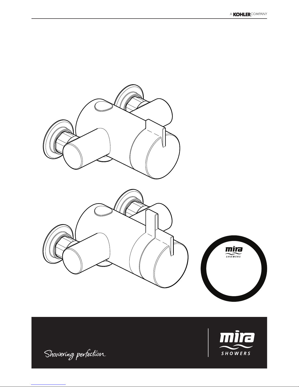
Mira Moto, Mira Pace†, Mira Minilite† and Mira Miniduo
†
(†including Eco Models)
Thermostatic Mixers
These instructions must be left with the user
Installation and User Guide
For SPARES, ADVICE
or REPAIRS
Please call us on
0844 571 5000
(UK Only)
Page 2

2
CONTENTS
Introduction 2
Type 2 Valves 2
Guarantee 3
Recommended Usage 3
Patents and Design Registration 3
Safety Warnings 3
Pack Contents 4
Exposed Thermostatic Mixers 4
Built-in Thermostatic Mixers 5
Valve Combinations 6
Specications 7
Installation 9
Suitable Plumbing Systems 9
General 9
Exposed Thermostatic Mixers 10
Adjustable Elbow Installation 13
Flow Regulators 19
Operation 22
Commissioning 23
Maximum Temperature Setting 23
Fault Diagnosis 24
User Maintenance 24
Filter Replacement 24
Lubricants 25
Cleaning 25
Accessories 25
Spare Parts 26
If you experience any difficulty with the
installation or operation of your new
thermostatic mixer, please refer to ‘Fault
Diagnosis’, before contacting Kohler Mira Ltd.
Our contact details can be found on the back
cover of this guide.
INTRODUCTION
Thank you for purchasing a quality Mira product. To
enjoy the full potential of your new product, please
take time to read this guide thoroughly, having
done so, keep it handy for future reference.
The Mira Moto, Mira Minilite and Mira Minilite Eco
are thermostatic mixers with a single control lever
for on/off and temperature control.
The Mira Pace, Mira Pace with Eco Showerhead,
Mira Pace with Adjustable Inlet Elbows, Mira
Miniduo and Mira Miniduo with Eco Showerhead
are thermostatic mixers with separate on/off and
temperature controls.
The thermostatic mixers incorporate a wax
capsule temperature sensing unit, which provides
an almost immediate response to changes in
pressures or temperature of the incoming water
supplies to maintain the selected temperature. An
adjustable maximum temperature stop is provided
which limits the temperature to a safe level.
Inlet lters are tted to protect the thermostatic
cartridge.
Type 2 Valves
These products have been certied as Type 2
valves under the BUILDCERT TMV2 scheme.
They also comply with the Water Supply (water
ttings) Regulations 1999.
For Type 2 Valves refer to the TMV2 Requirements
Manual.
Application
The approved designations for Type 2 Valves
are as follows:
Models Designation
Moto, Minilite LP-S, HP-S, HP-SE
#
#
the economy designation is achieved with the
tting of the outlet ow regulator.
Models Designation
Pace, Miniduo LP-S, HP-S
Important!Thettingofanyowregulatorto
Pace or Miniduo models will invalidate TMV2
compliance due to the minimum ow rate
requirements. Do not t ow regulators in
TMV2 applications to these models.
Page 3

3
Guarantee
For domestic installations, Mira Showers
guarantee the products listed in this guide against
any defect in materials or workmanship for a
period of three years from the date of purchase
(shower ttings for one year).
For non-domestic installations, Mira Showers
guarantee the products listed in this guide against
any defect in materials or workmanship for a
period of one year from the date of purchase.
For terms and conditions refer to the back cover
of this guide.
Recommended Usage
Application
Valve with
Fittings
Domestic
ü
Light Commercial
ü
Heavy Commercial
û
Healthcare
û
Patents and Design Registration
Patents:
GB: 2 291 693, 2 340 210, 2 392 225,
2 421 297
Euro: 1 672 257 DE, FR, GB, IT, NL, SE
USA: 7 240 850
Patent Applications:
Euro: 03254070.0
USA: 2006-0124758-A1, 2007-0221740-A1
Design Registration:
000793401-0005-00011
SAFETY WARNINGS
Mira thermostatic mixers are precision engineered
and should give continued safe and controlled
performance, provided:
1. They are installed, commissioned, operated and
maintained in accordance with manufacturer’s
recommendations.
2. Type 2 Valves are only used for applications
covered by their approved designations, refer
to the TMV2 Requirements Manual.
3. Periodic attention is given, when necessary,
to maintain the product in good functional
order.
Caution!
1. Read all of these instructions.
2. Retain this guide for later use.
3. Pass on this guide in the event of change of
ownership of the installation site.
4. Follow all warnings, cautions and instructions
contained in this guide.
5. Anyone who may have difculty understanding
or operating the controls of any shower should
be attended whilst showering. Particular
consideration should be given to the young,
the elderly, the inrm or anyone inexperienced
in the correct operation of the controls.
6. Rapid/Excessive movement of the ow and/
or temperature control levers may result in
momentary unstable blend temperatures.
7. Care is required when adjusting flow or
temperature, make sure that the temperature
has stabilised.
8. When this product has reached the end of its
serviceable life, it should be disposed of in a
safe manner, in accordance with current local
authority recycling, or waste disposal policy.
Page 4
4
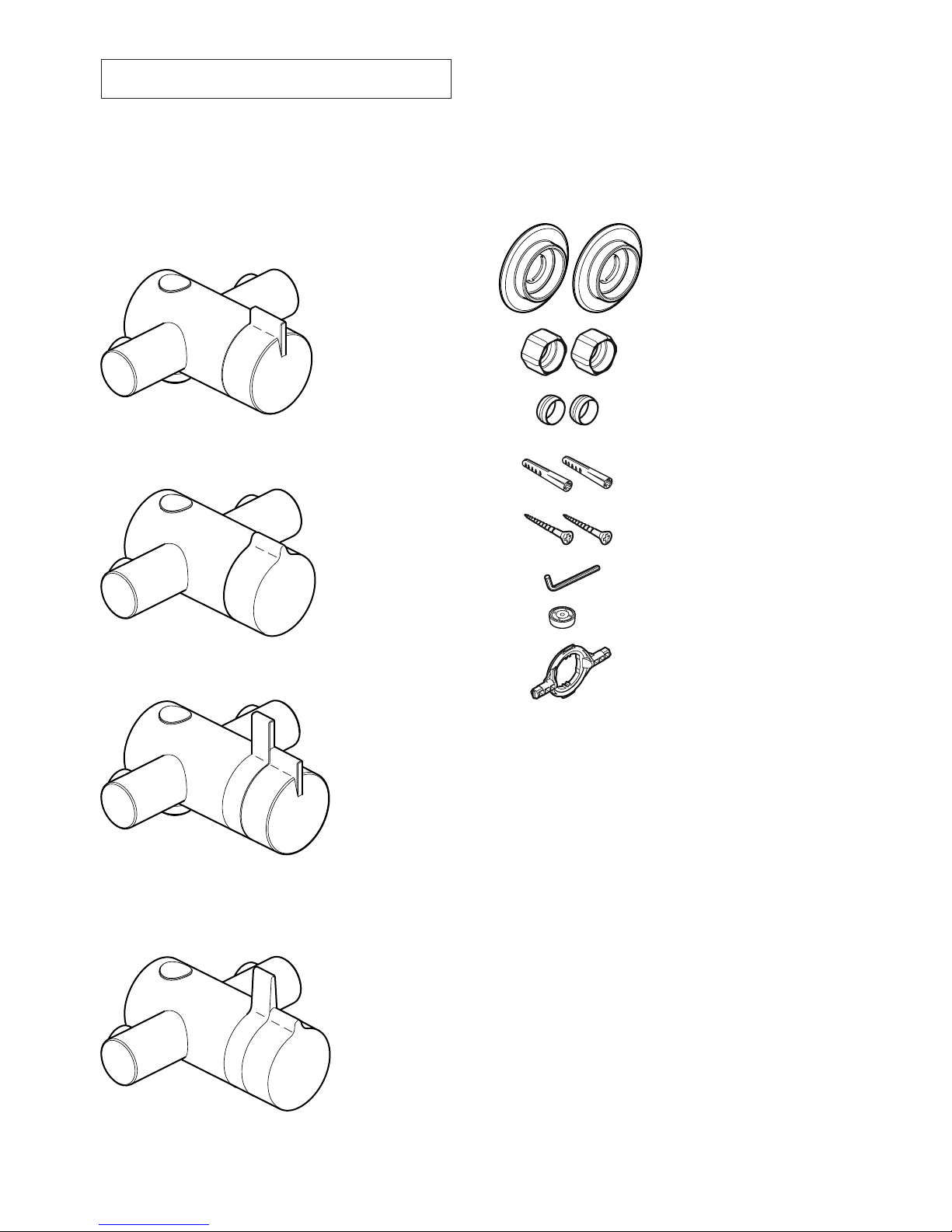
PACK CONTENTS
Tick the appropriate boxes to familiarise yourself
with the part names and to conrm that all of the
parts are included.
Exposed Thermostatic Mixers
q 1 x Thermostatic Mixing Valve
Documentation
q 1 x Guarantee Registration Document
q 1 x Installation Template
q 1 x TMV2 Requirements Manual
Component Pack
q 2 x Concealing Plates
q 2 x Compression Nuts
q 2 x Olives
q 2 x Wall Plugs
q 2 x Fixing Screws
q 1 x 2.5 mm Hexagonal Key
Mira Minilite EV or
Mira Minilite Eco EV
q 1 x ‘O’ Key
q 1 x Flow Regulator (refer to
section: ‘Flow Regulators’)
Mira Pace EV
Mira Pace with Adjustable Elbows
Mira Pace with Eco Showerhead EV
Mira Miniduo EV or
Mira Miniduo with Adjustable Elbows
Mira Miniduo with Eco Showerhead EV
Mira Moto EV
Page 5
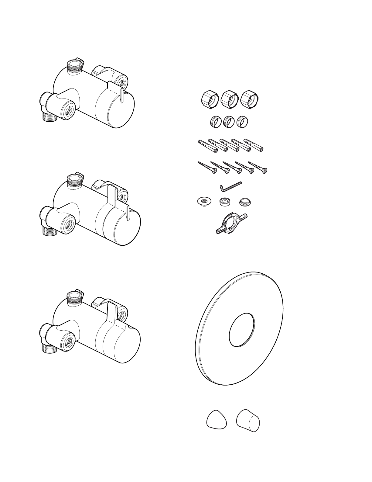
5
Component Pack
Mira Minilite BIV or
Mira Minilite Eco BIV
q 3 x Compression Nuts
q 3 x Olives
q 5 x Wall Plugs
q 5 x Fixing Screws
q 1 x 2.5 mm Hexagonal Key
q 1 x Concealing Plate
Assembly
Documentation
q 1 x Guarantee Registration Document
q 1 x Cardboard Building-in Shroud
q 1 x TMV2 Requirements Manual
q 1 x ‘O’ Key
q 1 x Flow Regulator (refer to
section: ‘Flow Regulators’)
q 1 x RAC Assembly
Mira Miniduo BIV or
Mira Miniduo with Eco Showerhead BIV or
Mira Miniduo with Eco Showerhead BIR
oror
or
Built-in Thermostatic Mixers
q 1 x Thermostatic Mixing Valve
Mira Pace BIV
Page 6

6
Valve Combinations
These thermostatic mixers are available with various shower ttings and water saving features, refer to
the table below to identify your mixer valve combination:
Mixer Valve
Shower
Fittings
Flow Regulator
Flow Rate Colour Comments
Moto EV /
Minilite EV
L14A 12 L/Min Red
Supplied in the component pack, designed to
be tted in the shower valve outlet
Pace EV /
Miniduo EV
L98B 12 L/Min Red
Supplied in the component pack, designed to
be tted in the shower valve outlet
Minilite BIV L14A 12 L/Min Natural
Supplied in the component pack, designed
to be tted between the shower hose and
RAC assembly
Minilite Eco EV L14A 6 L/Min Black
Factory tted in the shower valve outlet
(optional 8 L/Min (white/natural) flow
regulator supplied separately in the
component pack)
Minilite Eco BIV L14A 6 L/Min Black
Factory tted in the RAC assembly (optional
8 L/Min (white/natural) flow regulator
supplied separately in the component pack)
Miniduo BIV L98B
12 L/Min Natural
Supplied in the component pack, designed
to be tted between the shower hose and
RAC assemblyPace BIV L14D
Pace EV with
Adjustable Elbows
L14D 12 L/Min Red
Supplied in the component pack, designed to
be tted in the shower valve outlet
Pace with Eco
Showerhead EV
L98B with Eco
Showerhead
7.0 L/Min Olive Green
Supplied in the component pack, designed
to be tted between the shower hose and
shower valve outlet
Miniduo with Eco
Showerhead EV
L98B with Eco
Showerhead
7.0 L/Min Olive Green
Supplied in the component pack, designed
to be tted between the shower hose and
shower valve outlet
Miniduo with Eco
Showerhead BIV
L98B with Eco
Showerhead
7.0 L/Min Olive Green
Supplied in the component pack, designed
to be tted between the shower hose and
RAC assembly
Miniduo with Eco
Showerhead BIR
Eco BIR
Showerhead
7.3 L/Min
Bright
Green
Supplied with the Eco BIR shower head,
designed to be tted between the wall plate
and inlet nipple
Flow regulators are supplied for installation on high pressure systems (above 0.5 bar).
For gravity fed or other low pressure systems do not t the ow regulator.
The Mira Minilite Eco has a ow regulator factory tted in the shower valve outlet or RAC assembly,
on older combination boiler systems it may be necessary to replace this 6 L/Min ow regulator with the
8 L/Min ow regulator (supplied), in order to achieve the minimum ow rate required to ignite and run
the boiler.
Important! The tting ofanyow regulator to Paceand Miniduo models willinvalidate TMV2
compliance due to the minimum ow rate requirements. Do not t ow regulators in TMV2
applications to these models.
For further information on how and where to t the ow regulator, refer to section: ‘Flow Regulators’.
Page 7

7
SPECIFICATIONS
For Type 2 Valves, the supply conditions
specified in the TMV2 Requirements Manual
take precedence over the operating parameters
which follow.
Pressures
• Max Static Pressure: 10 Bar.
• Max Maintained Pressure: 5 Bar.
• Min Maintained Pressure (Gravity System):
0.1 Bar (0.5 Bar for models with Eco
Showerhead). (0.1 bar = 1 Metre head from
cold tank base to showerhead outlet).
Note! For gravity fed or other low pressure
systems (0.5 bar or below) do not t the outlet
ow regulator (where applicable).
• For optimum performance supplies should be
nominally equal.
Temperatures
• Factory Pre-set (Blend) Shower: 41°C.
• Optimum Thermostatic Control Range: 35°C
to 43°C (achieved with supplies of 15°C cold,
65°C hot and nominally equal pressures).
• Recommended Hot Supply: 60°C to 65°C
Note! The mixing valve can operate at
higher temperatures for short periods without
damage, however this could detrimentally
affect thermostatic performance. For safety
and performance reasons it is recommended
that the maximum hot water temperature is
limited to 65°C.
• Cold Water Range: up to 25°C.
• Minimum Recommended Differential between
Hot Supply and Outlet Temperature: 12°C.
Thermostatic Shut-down
• For safety and comfort the thermostat will
shut off the mixing valve within 2 Seconds if
either supply fails (achieved only if the blend
temperature has a minimum differential of
12°C from either supply temperature).
Connections
• Inlets: 15 mm Compression.
• Outlet: ½” BSP Flat Face / 15 mm
Compression
• Standard connections are: hot - left, cold -
right, outlet - bottom (EV models), top (BIV
and BIR models).
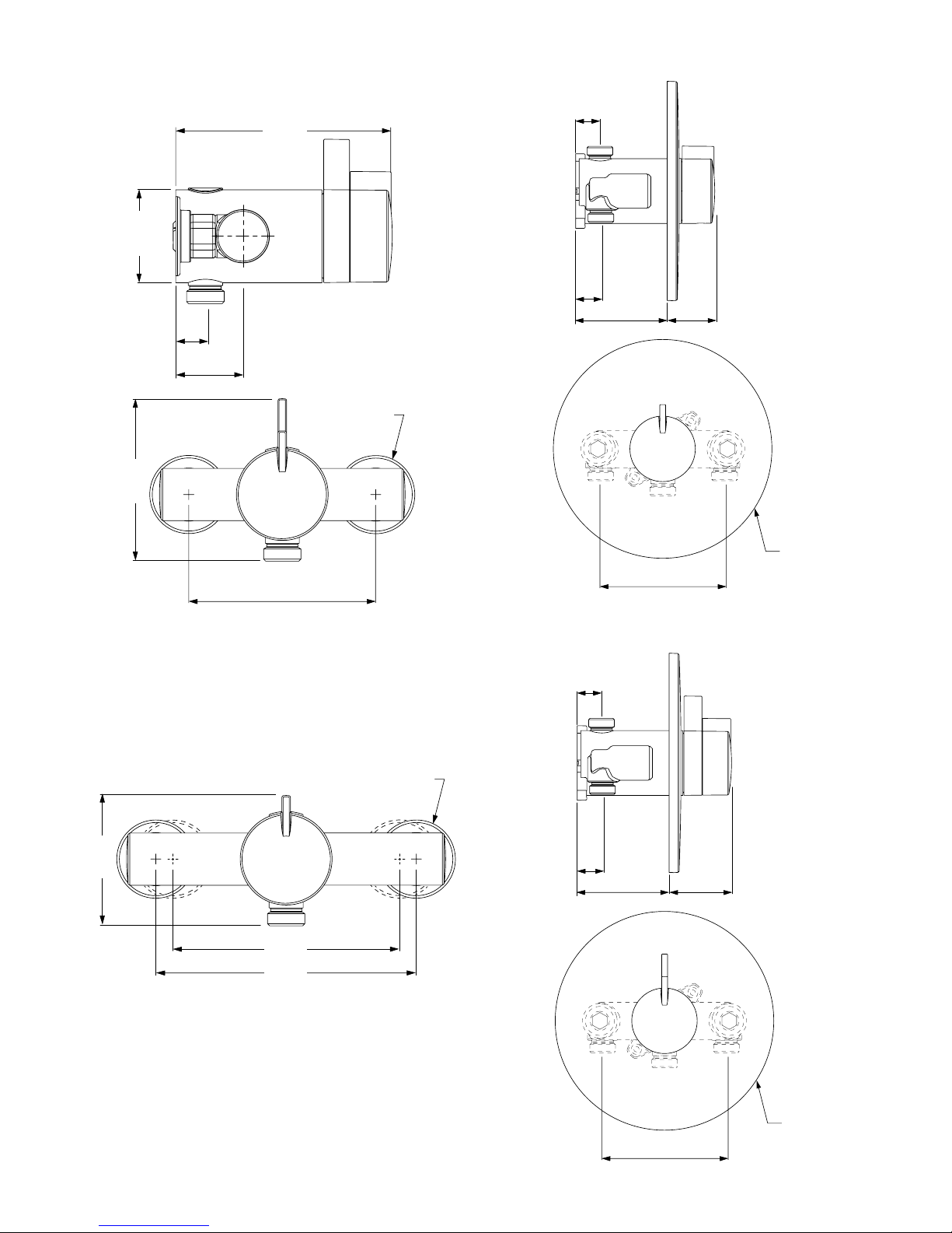
Dimensions
Moto, Minilite and Minilite Eco EV
Ø46
39
17
See Note! below
(All dimension in millimetres)
113
Ø54
76.5
110
Flow Rates
Typical Flow Rates
Mira Miniduo with Mira L98B Shower Fittings:
Supply Pressure (bar)
Flow Rate (L/Min)
0
10
20
30
40
50
01 23
45
0.5 1.5 2.5 3.5 4.5
Page 8
8
Minilite and Minilite Eco BIV
Pace, Miniduo BIV and Miniduo with Eco
Showerhead BIV / BIR
103
103
Ø183
56-76 39-59
21
20
56-76 53-73
21
20
Ø183
Miniduo and Pace with Adjustable Elbows
Ø46
76.5
133
153
Pipe Centres at extremes of elbow adjustment
Pace, Pace with Eco Showerhead, Miniduo and
Miniduo with Eco Showerhead EV
Note! If you are retro-tting your mixing valve onto
existing pipework, an Adjustable Elbow Pack is
available if required, refer to section: ‘Accessories’.
39
17
110
Ø46
See Note! below
125
Ø54
95
Page 9
9
INSTALLATION
Suitable Plumbing Systems
Gravity Fed:
The thermostatic mixer must be fed from a cold
water cistern (usually tted in the loft space) and
a hot water cylinder (usually tted in the airing
cupboard) providing nominally equal pressures.
Mains Pressurised Instantaneous Hot Water
System (Combination Boiler):
The thermostatic mixer can be installed with
systems of this type with balanced pressures.
(Recommended Minimum Maintained Pressure:
1.0 Bar).
Note! On combination boiler systems we
recommend that the thermostatic mixer is
operated in the maximum ow position in order to
achieve the minimum ow rate required to ignite
and run the boiler.
Unvented Mains Pressure System:
The thermostatic mixer can be installed with an
unvented, stored hot water system.
Pumped System:
The thermostatic mixer can be installed with an
inlet pump (twin impeller). The pump must be
installed in a suitable location and in accordance
with its instructions.
General
Installation must be carried out in accordance
with these instructions, and must be conducted by
designated, qualied and competent personnel.
The installation must comply with the “Water
Supply Regulations 1999 (Water Fittings)” or any
particular regulations and practices, specied by
the local water company or water undertakers.
Note! Make sure that all site requirements
correspond to the information given in section:
‘Specications’. For Type 2 Valves see also
supply conditions in the TMV2 Requirements
Manual.
1. The Mixer must not be installed in an area
where it may freeze.
2. For stud partitions alternative xings may be
required.
3. Isolating valves must be installed close to the
Mixer for ease of maintenance.
4. Pipework must be rigidly supported and avoid
any strain on the connections.
5. Pipework dead-legs should be kept to a
minimum.
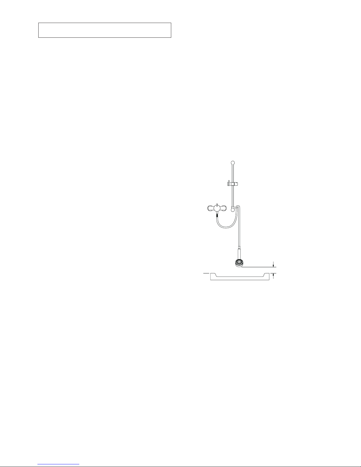
6. Decide on a suitable position for the Mixer.
The position of the Mixer and the Shower
Fittings must provide a minimum gap of 25 mm
between the spill-over level of the shower tray/
bath and the showerhead (refer to illustration).
This is to prevent back-siphonage. For further
information on the installation of your Shower
Fittings, refer to the Fittings Installation and
User Guide.
Note! Only use Shower Fittings recommended
by the manufacturer or supplier.
25 mm
Spill Over
Level
Page 10

10
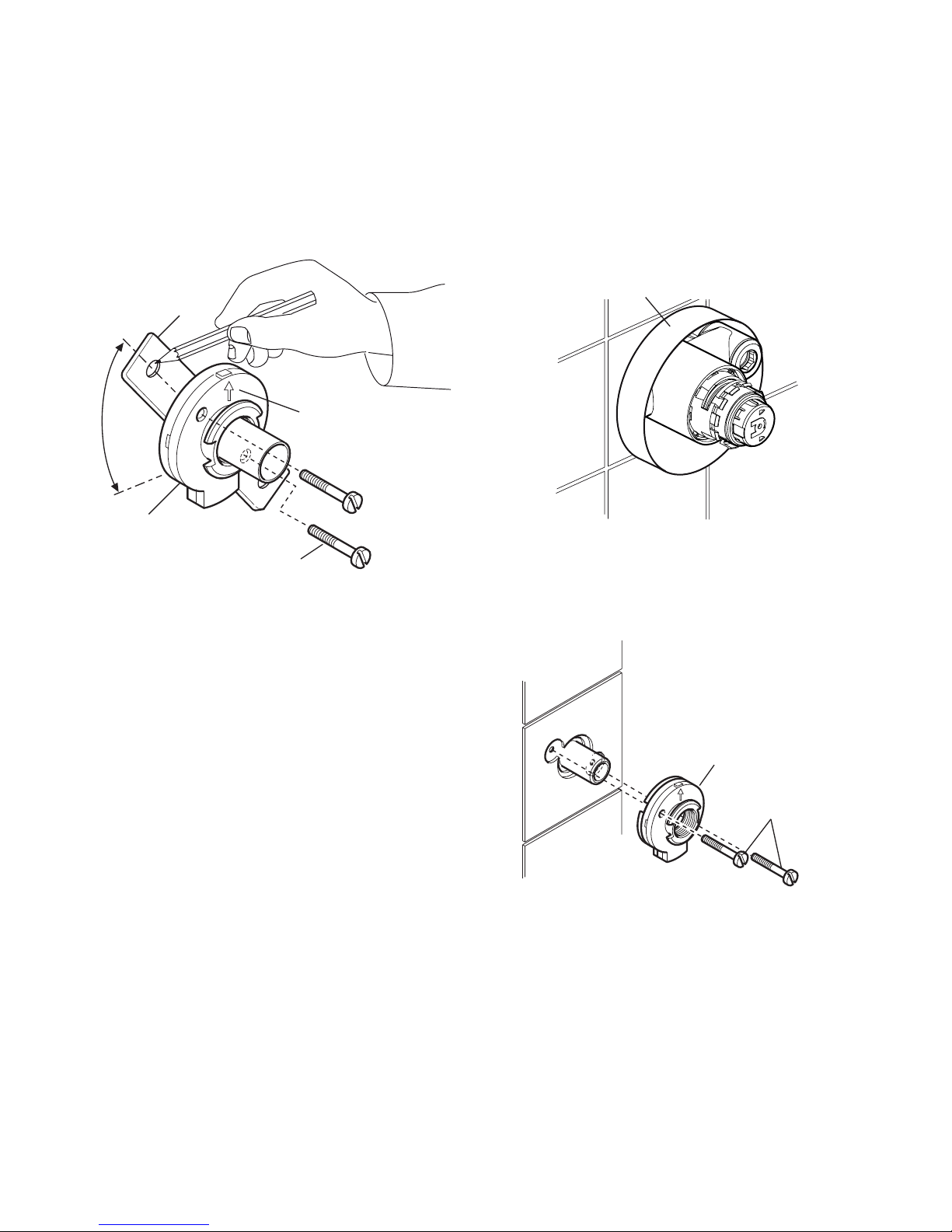
Exposed Thermostatic Mixers
For Built-in Thermostatic Mixers go to section:
‘Installation, Built-in Thermostatic Mixers’.
1. The thermostatic mixer can be installed with
rear, rising or falling supply inlets. Decide
on the most appropriate method for your
installation, and if necessary, loosen the
grubscrews and rotate the inlet elbows to
suit.
Important! Make sure that the elbows are
pushed fully onto the mixer before tightening
the grubscrews, do not overtighten.
2. Use the installation template to mark the
positions of the holes for the backplate and
the pipe centres.
For rising or falling supplies the pipe positions
should be set 39 mm from the centre of pipe
to the nished wall at 110 mm centres.
Note! If you are retro-tting your mixing valve
onto existing pipework, an Adjustable Elbow
Pack is available if required, refer to section:
‘Accessories’.
39 mm
3. For solid walls drill the holes for the backplate
with a 6 mm drill and insert the wall plugs
(supplied). For other types of wall structure
alternative fixings may be required (not
supplied).
6 mm Drill
Wall Plug
4. For Rear Entry Supplies Only:
a) Drill the holes for the supply pipes at
110 mm centres.
Note! Recess the inlet holes Ø19 mm x
2 mm deep to allow for the concealing
plates.
5. Fit the supply pipework: Hot - Left, Cold
- Right. The inlet pipework should extend
23 mm from the nished wall surface.
Note! If it is not possible to install the
mixer with this pipework conguration follow
instruction 6.
23 mm from nished
wall surface
Elbow
Recess Ø19 mm
x 2 mm deep
23 mm
110 mm
HOT
COLD
Page 11

11
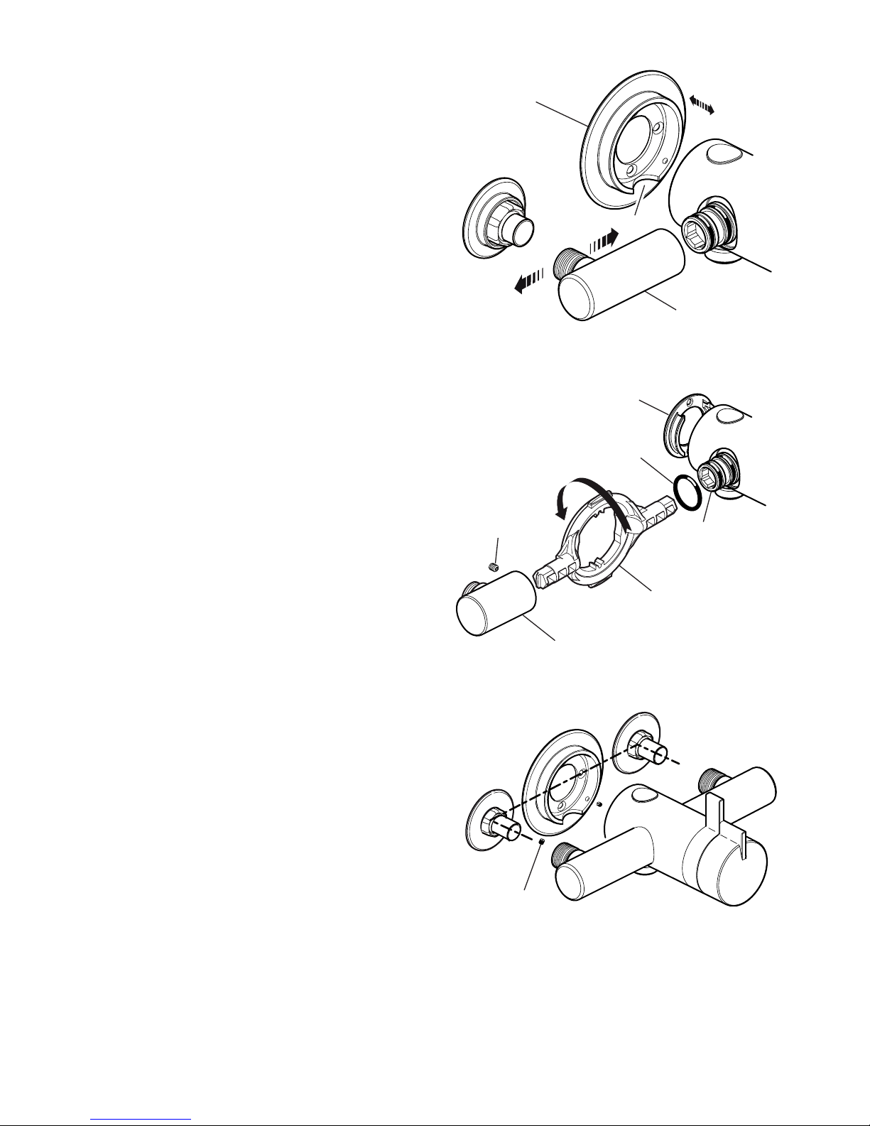
6. Reversed Inlet Supplies Only:
a) Using a suitable tool, carefully remove the
plug cap from the centre of sealing plug
to reveal keyway.
b) Remove the sealing plug using the ‘O’ key
(supplied) or a 12 mm hexagonal key.
c) Unscrew the outlet nipple using the
‘O’ key (supplied) or a 12 mm hexagonal
key.
Note! On Mira Minilite Eco models
carefully remove the ow regulator from
the outlet nipple rst.
d) Ret the sealing plug and outlet nipple in
the opposite outlets and tighten.
Note! Make sure that the ‘O’ seals are
correctly tted.
Note! On Mira Minilite Eco models ret
the ow regulator.
e) Rotate the mixer 180°.
f) The control knob(s) will have to be
realigned, this can be completed in
section: ‘Commissioning’.
Plug Cap
Sealing Plug
‘O’ Seal
7. Remove the backplate from the mixer by
loosening the grubscrews with a 2.5 mm
hexagonal key (supplied).
8. Secure the backplate to the wall using the
screws (supplied).
Screw
Backplate
Page 12
12
9. For Rear Entry Supplies Only:
a) Fit the concealing plates over the inlet
pipes.
Note! Apply silicone sealant to the back
face of the ange.
Apply Silicone Sealant
Concealing Plate
10. Caution! It is essential at this point
that the supply pipework is thoroughly
ushedthroughbeforeconnectiontothe
mixer. Failure to do so may result in product
malfunction and will not be covered under the
guarantee.
11. Fit the compression nuts and olives onto the
pipework.
12. Align the mixer with the pipework and t onto
the backplate.
Important! Make sure that the hot and cold
inlets on the mixer correspond with the hot and
cold inlet supplies.
13. Tighten the compression nuts onto the mixer
with a suitable wrench.
Caution! Take care not to damage the chrome
surfaces.
14. Tighten the grubscrews to secure the mixer to
the backplate.
15. Fit the shower ttings, refer to your shower
fittings installation and user guide for
instructions.
Important! For high pressure systems (above
0.5 bar) make sure that the ow regulator
(supplied) is tted, refer to section: ‘Flow
Regulators’.
16. Turn on the hot and cold water supplies and
check for leaks.
17. Before using the shower, refer to section:
‘Commissioning’.
Compression Nut
Olive
Page 13
13
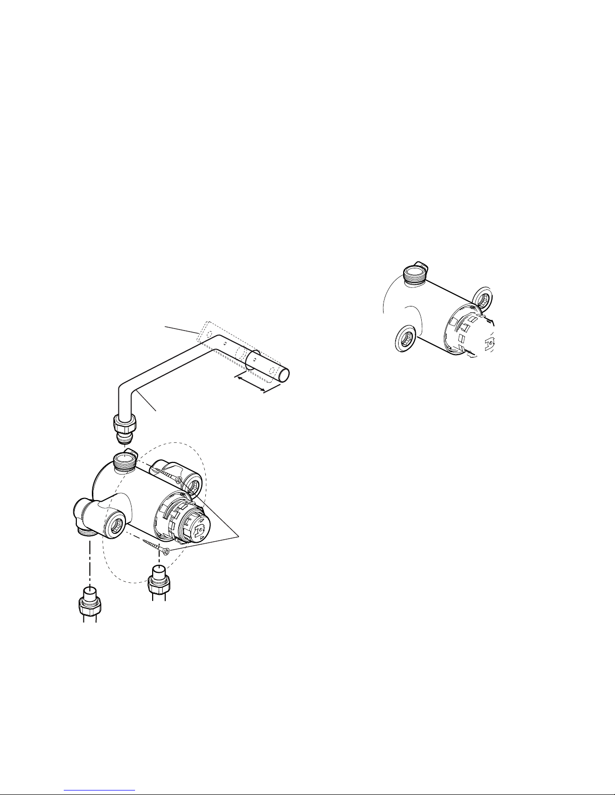
Adjustable Elbow Installation
1. Unscrew the elbow grubscrews on the
thermostatic mixer with a 2.5 mm hexagonal
key (supplied with the thermostatic mixer), pull
off the inlet elbows and discard.
2. Using the ‘O’ key (supplied with the thermostatic
mixer) or a 12 mm hexagonal key, unscrew the
inlet nipples and discard.
3. Fit the new adjustable elbow inlet nipples and
tighten with the ‘O’ key.
4. Make sure that the ‘O’ seal is tted and push the
new elbow fully onto the inlet nipple. Tighten
the grubscrew with a 2.5 mm hexagonal key.
5. Remove the backplate from the mixer by
removing the grubscrew with a 2.5 mm
hexagonal key.
6. Draw a centre line between the inlet pipework
and, using the adjustable backplate as a
template, mark the position of the adjustable
backplate xing holes.
7. For solid walls drill the holes for the backplate
with a 6 mm drill and insert the wall plugs
(supplied). For other types of wall structure
alternative fixings may be required (not
supplied).
8. Secure the backplate to the wall using the
screws (supplied).
9. Align the mixer with the pipework and t onto
the backplate.
Note! Make sure that the pipes are pushed
fully into the inlet connectors.
10. Tighten the compression nuts onto the mixer
with a suitable wrench.
Caution! Take care not to damage the chrome
surfaces.
11. Tighten the adjustable backplate grubscrews
with a 2 mm hexagonal key (supplied) to
secure the mixer to the backplate.
Grubscrew
Inlet Elbow
‘O’ Key
Inlet Nipple
Backplate
Grubscrew
‘O’ Seal
Adjustable
Backplate
Adjustable
Elbow
11 mm
10 mm
Cutout
Page 14

14
Built-in Thermostatic Mixers
1. Carefully remove the concealing cap from the
control knob.
2. Unscrew the grubscrew using a 2.5 mm
hexagonal key (supplied) and pull off the
control knob(s).
Note! The ow control knob must be in the off
position in order to remove it.
Flow Control Knob
Temperature
Control Knob
Grubscrew
Grubscrew
Concealing Cap
Concealing Cap
Control Knob
3. Carefully remove the concealing ring from the
concealing plate.
Concealing Ring
Concealing Plate
4. Determine the route for the hot and cold
supply pipework and for the outlet pipework.
When connecting to the BIV shower ttings it
is recommended that the outlet be positioned
to one side of the mixer. This is to prevent
the exible hose from obstructing the shower
controls (refer to illustration).
103 mm
Outlet Pipe BIV
Cold InletHot Inlet
Thermostatic
Mixer
Alternative Pipe layouts
Outlet Pipe BIV
5. Mark the routes for the hot and cold supply
pipework at 103 mm centres (Hot - Left, Cold
- Right).
Note! If it is not possible to install the
mixer with this pipework conguration follow
instruction 6.
Falling Supplies: For falling supplies loosen
the grubscrew on each elbow using the 2.5
mm hexagonal key (supplied). Remove the
elbows and install on opposite sides.
Important! Make sure that the elbows are
pushed fully onto the mixer before tightening
the grubscrews, do not overtighten.
Page 15

15
6. Reversed Inlet Supplies Only:
a) Remove the sealing plug using the ‘O’ key
(supplied) or a 12 mm hexagonal key.
b) Remove the outlet nipple using the ‘O’ key
(supplied) or a 12 mm hexagonal key.
c) Ret the sealing plug and outlet nipple in
the opposite outlets and tighten.
Note! Make sure that the ‘O’ seals are
correctly tted.
d) Rotate the mixer 180°.
e) If necessary, use the 2.5 mm hexagonal
key (supplied) to loosen the grubscrew in
each elbow.
Note! It is important to retract the
grubscrews sufciently to clear the ‘O’
seals and the inlet ange to avoid causing
damage to the seals.
f) Remove the elbows and install on
opposite sides. Make sure that the elbows
are pushed fully onto the inlet stubs then
retighten the grubscrews using the 2.5
mm hexagonal key.
Caution! Do not overtighten.
7. Determine the position of the mixer and draw
around the inside of the concealing ring.
8. Carefully cut away the plasterboard and/or
brick work to a depth of between 56 and 76 mm
from the nishedwallsurface.
Important! Take care to stay within the marked
out diameter otherwise the concealing ring will
not seal.
Finished Wall
Surface
56 - 76 mm
Rear Mounting
9. Fit the concealing ring over the mixer body,
then, holding the mixer level, central and
square in the hole, mark the positions of the
two backplate xing holes on the wall.
Backplate Fixing Hole
Backplate Fixing Hole
10. For solid walls drill two 6 mm holes for the
wall plugs. For other types of wall structure
alternative fixings may be required (not
supplied).
11. Caution! It is essential at this point
that the supply pipework is thoroughly
ushedthroughbeforeconnectiontothe
mixer. Failure to do so may result in product
malfunction and will not be covered under the
guarantee.
Top
Concealing Ring
Plug Cap
Sealing Plug
‘O’ Seal
Outlet Nipple
Page 16
16
12. Insert the wall plugs (supplied) and attach the
mixer to the wall or to the timber noggin with
the screws provided.
13. Fit the compression nuts and olives onto the
pipework, connect the pipes and tighten the
compression nuts.
Important! Make sure that the outlet pipework
protrudes through a Ø25 mm hole in the wall
or stud partition by approximately 40 mm and
temporarily cap off.
Note! For stud partition installations where
access to the rear of the partition is possible,
t the RAC wallplate over the outlet pipework
on the inside of the partition.
For stud partition installations where access
to the rear of the wall is not possible, follow
instructions for solid wall installations, making
sure that suitable wall xings (not supplied) are
used to secure the wallplate to the outside of
the stud partition.
Screws
Outlet Pipe to Fittings
Hot Supply
Cold Supply
40 mm
RAC Wallplate
14. Turn on the water supplies and check for
leaks.
15. Determine the nished wall position (e.g. tile
thickness). Turn off the water supply, carefully
uncap the outlet pipe and cut to length, the
outlet pipe must protrude through the nished
wall surface by 21–23 mm.
Note! Remove any burrs from the pipes before
proceeding.
16. For solid wall installations or stud partition
installations without rear access go to
instruction 21.
For stud partition installations with access
to the rear of the partition continue with
instruction 17.
17.Finish the wall (e.g. tiles).
Important! Make sure that you use the
cardboard building-in shroud when nishing
the wall. This will protect the valve and make
sure that you tile up to the correct diameter.
Caution! Make sure that the nished wall is
within the maximum and minimum limits and to
an even depth (no greater than 2 mm variation)
or the controls will not t correctly.
Page 17
17
21. Loosely attach the RAC backplate to the RAC
wallplate, using the two backplate screws
provided.
22. Place the RAC backplate/wallplate assembly
over the outlet pipe with the arrow pointing
vertically up. The screw holes should be at
40° to the horizontal.
23. Mark the positions of the two RAC wallplate
xing holes.
Wallplate
RAC Backplate
Backplate Screws
Arrow
40°
24. Remove the assembly from the wall and
separate the backplate from the wallplate.
25. For solid walls drill two 6 mm holes for the
wall plugs. For other types of wall structure
alternative fixings may be required (not
supplied). If necessary, make a recess 6 mm
deep to accept the wallplate for ush tting of
the outlet to the wall surface.
Caution! Make sure that you do not drill into
pipework in the wall.
26. Fit the two wall plugs supplied and secure
the wallplate to the wall with the two wallplate
screws.
27.Make sure that there is clearance behind the
wallplate and temporarily t the two backplate
screws into the wallplate. This will prevent
the xing holes from becoming blocked with
plaster or grout.
28. Finish the wall, e.g. tiles. then remove the two
backplate screws.
Important! Make sure that you use the
cardboard building-in shroud when nishing
the wall. This will protect the valve and make
sure that you tile up to the correct diameter.
Caution! Make sure that the nished wall is
within the maximum and minimum limits and to
an even depth (no greater than 2 mm variation)
or the controls will not t correctly.
Cardboard Building-in Shroud
29. Place the backplate over the outlet pipe with
the arrow pointing vertically up and tighten the
two backplate screws. Make sure that the foam
seal abuts the nished wall surface.
RAC Backplate
Backplate
Screws
Page 18
18
30.Check that the blue ‘O’ seal is tted inside the
backplate nut. Fit the olive and the backplate
nut over the outlet pipe and loosely tighten
the nut.
31. To prevent the backplate from turning while
tightening the nut, t the retaining ring over the
backplate nut making sure the slots engage
with the screws on the backplate, hold the
retaining ring with a wrench while tightening
the backplate nut. Remove the retaining ring
after use.
32. Check that the second ‘O’ seal (black) is tted
to the outside of the backplate nut. Press the
elbow onto the backplate, make sure that the
clips on the elbow engage with the backplate.
33. Slide the retaining ring over the elbow and
engage with the elbow clips. Note! The
retaining ring must be engaged correctly to
lock the elbow to the backplate, rotate the
retaining ring to the postition illustrated.
34. Press the shroud over the elbow, make sure
that it engages with the lugs on the backplate.
35. Fit the concealing ring over the mixer and mark
the positions of the three xing holes.
36. For solid walls drill three 6 mm holes for the
wall plugs. For other types of wall structure
alternative fixings may be required (not
supplied).
Caution! Make sure that you do not drill into
pipework in the wall.
37. Insert the wall plugs (supplied) and attach the
concealing ring to the wall with the screws
provided.
Important! Apply silicone sealant to the
groove on the rear face of the concealing ring
38. Fit the concealing plate to the concealing ring.
39. Ret the control knobs.
40 Fit the shower ttings, refer to your shower
fittings installation and user guide for
instructions.
Important! For high pressure systems (above
0.5 bar) make sure that the ow regulator
(supplied) is tted, refer to section: ‘Flow
Regulators’.
41.Turn on the hot and cold water supplies and
check for leaks.
42.Before using the shower, refer to section:
‘Commissioning’.
Backplate Nut
Retaining Ring
Olive
Concealing Ring
Apply Silicone
Sealant
Screws
Retaining Ring shown
correctly engaged with
Elbow
Elbow
Slot
Screw
Page 19

19
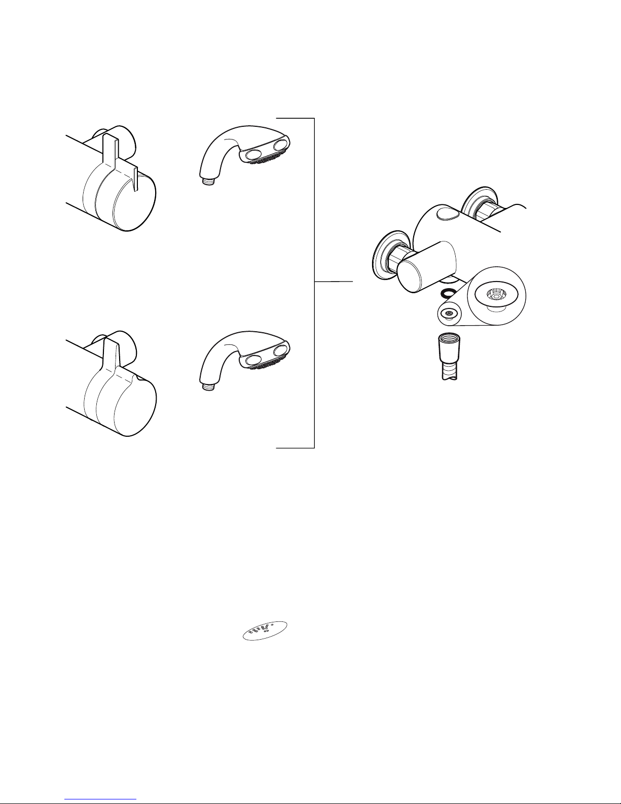
Mira Minilite EV, Mira Minilite Eco EV
Mira Moto EV
Page 20

20
RAC Assembly (will vary
depending on model)
Hose Washer
Flow
Regulator
Hose
Mira Minilite BIV
A 12 L/Min ow regulator (natural) is supplied
separately in the component pack, designed to
be tted between the shower hose and RAC
assembly.
Mira Miniduo BIV, Pace BIV
A 12 L/Min ow regulator (natural) is supplied
separately in the component pack, designed to
be tted between the shower hose and RAC
assembly.
Mira Miniduo with Eco Showerhead BIV
A 7.0 L/Min ow regulator (olive green) is supplied
separately in the component pack, designed to
be tted between the shower hose and RAC
assembly.
Page 21
21
Page 22

22
Mira Miniduo with Eco Showerhead BIR
A 7.3 L/Min flow regulator (bright green) is
supplied with the BIR showerhead, designed to
be tted between the wall plate and inlet nipple.
Refer to your shower fittings installation and
user guide.
Wall Plate
Inlet Nipple
Flow Regulator
OPERATION
Mira Moto, Mira Minilite and Mira Minilite Eco
thermostatic mixers have a single sequential
control lever for on/off and temperature control.
The control lever operates anti-clockwise in the
following sequence:
• Off
• On
• Cold
• Warm
• Maximum Preset Temperature
Mira Pace, Mira Pace with Eco Showerhead,
Mira Miniduo and Mira Miniduo with Eco
Showerhead thermostatic mixers have separate
control levers for on/off and temperature.
The control levers operate as shown below:
Maximum Preset
Temperature
Off
Off
Turn the Temperature Control
Handle clockwise to decrease the
temperature and anticlockwise to
the preset maximum temperature
Turn the Flow Lever
anticlockwise to the
preset maximum ow
On
Hot
Cold
Note! For high
pressure systems
the user has limited
ow control as
the outlet ow is
controlled by the
ow regulator
Page 23

23
COMMISSIONING
Maximum Temperature Setting
Before using the shower the maximum temperature
must be checked to make sure that it is at a safe
level. It has been preset to approximately 41°C at
the factory but due to variations in site conditions
the maximum temperature may need adjustment.
Note! Make sure that the hot water temperature
is at least 55°C and that there is sufcient supply.
For Type 2 installations the maximum blend
temperature is determined by the application,
refer to the TMV2 Requirements Manual.
1. Turn on the mixer to the maximum temperature
and maximum ow (i.e. fully anticlockwise) and
allow the temperature to stabilise.
If the temperature is too hot or too cold adjust
as follows:
2. Carefully remove the concealing cap from the
control knob.
3. Loosen the control lever grubscrew with the
2.5 mm hexagonal key (supplied) and pull off
the control lever.
4. If applicable unscrew the hub retaining screw
with a 2.5 mm hexagonal key.
Note! Do not remove the hub.
Page 24

24
USER MAINTENANCE
If you require a Mira trained service engineer
or agent, refer to section: ‘Customer
Services’.
Filter Replacement
Exposed Models
1. Isolate the water supplies.
2. Turn on the ow control knob to relieve water
pressure and to drain any residual water.
3. Unscrew the shower hose or rigid riser from
the mixer outlet.
4. Using a suitably sized wrench loosen both
compression nuts.
5. Using a 2.5 mm hexagonal key (supplied)
unscrew the grubscrews securing the mixer
to the backplate.
6. Remove the mixer.
7. The lters are retained in the elbow inlet,
remove them and inspect for debris blockage.
Clean each of the lters under a jet of water to
remove any lodged particles.
Compression
Nuts
Hexagonal Key
Grub Screw
Filter
Elbow
FAULT DIAGNOSIS
Symptom:
CauseRectication:
‘User Maintenance’.
Symptom:
CauseRectication:
Symptom:
CauseRectication:
Page 25

25
Concealing Plate
Concealing Cap
Grubscrew
Control
Knobs
Concealing Ring
8. Ret or replace the lters and reassemble in
reverse order.
9. Restore the water supplies and check for
leaks.
Built in Models
1. Isolate the hot and cold water supplies.
2. Turn on the ow control knob to relieve water
pressure and to drain any residual water.
3. Return the ow control knob to the off position
and carefully remove the concealing cap.
4. Unscrew the grubscrew using a 2.5 mm
hexagonal key (supplied) and pull off the
control knob(s).
5. Carefully unclip and remove the concealing
plate from the backplate.
Note! Use a screwdriver in the cutout to assist
separation.
6. Unscrew the filter caps with the ‘O’ key
(supplied) or a 12 mm hexagonal wrench and
remove the lters.
Note! Use pliers to assist if necessary.
‘O’ key
Filter Cap
Filter
7.Clean each of the lters under a jet of water to
remove any lodged particles.
8. Ret or replace the lters and tighten the lter
caps.
Note! Make sure that the seal is tted correctly
and not damaged.
9. Turn on the hot and cold water supplies and
Page 26

26
SPARE PARTS
Exposed Models
1663.168
Pipe Concealing
Plates (x2)
Note! All spare parts supplied individually unless
stated otherwise.
1663.154
Elbow Connector
Assembly
1663.158
Outlet Nipple
1663.160
Outlet Plug
1663.153
Elbow Assembly
1663.157
Backplate Assembly
1663.150 (Moto)
Control Lever Assembly
1663.151
Hub and Bearing
Assembly
1663.163 (Miniduo)
Control Lever Assembly
1663.165
Hub and Retainer
Assembly
A
C
C
C
C
B,C
B
B
1663.155
Filter Pack (x2)
1663.159 Seal Pack - components identied ‘A’
1663.161 Component Pack - components
identied ‘B’
1663.162 Screw Pack - components identied ‘C’
1663.265 Flow Regulator Pack (containing all ow
regulators for all models, not illustrated)
1663.164 (Pace)
Control Lever Assembly
A
C
C
C
1663.156 (Minilite)
1663.268 (Minilite Eco)
Control Lever Assembly
1663.152
Thermostatic
Cartridge Assembly
1663.166
Thermostatic
Cartridge Assembly
Moto, Minilite and Minilite Eco
Pace, Pace with Eco Showerhead,
Miniduo and Miniduo with Eco Showerhead
A
C
A
A
1663.335
Adjustable Elbow
Service Pack
1663.340
Adjustable Inlet
Nipple
Page 27

27
Page 28
28
1082138-W2-N (1663, 1694) (B94A-D) © Kohler Mira Limited, October 2013
Guarantee
This guarantee is in addition to your statutory rights
and is subject to the following conditions:
Note!
The guarantee does not cover:
 Loading...