

Page 1

SHOWER FITTINGS
INSTALLATION & USER GUIDE
These instructions are to be left with the user
1
MIRA ECO
Page 2

CONTENTS
INTRODUCTION
Introduction 2
General 2
Pack Contents 3
Pack Contents 4
Specifi cations 5
Pressures 5
Dimensions 5
Flow Rates 5
Installation 6
RAC Assembly 6
Mira Eco Shower Fittings 8
Operation 9
User Maintenance 10
Fault Diagnosis 10
Cleaning 10
Spare Parts 11
Customer Service 12
If you experience any difficulty with the
installation or operation of your new shower
fi ttings, please refer to ‘Fault Diagnosis’,
before contacting Kohler Mira Ltd. Our contact
details can be found on the back cover of
this guide.
Thank you for purchasing a quality Mira product. T o
enjoy the full potential of your new product, please
take time to read this guide thoroughly, having
done so, keep it handy for future reference.
Mira ECO adjustable shower fi ttings are designed
to give a satisfactory shower over a range
of pressures. These fittings are suitable for
pressures between 0.5 and 5.0 bar and are
available in chrome or white fi nishes.
General
1. Make sure that the shower fi ttings are installed
by a competent installer.
2. Installations must comply with Water Regulations
(Bye-Laws, Scotland), and any other Local
Regulations and Building Regulations in force
at the time of installation.
3. Before installation carefully inspect the new
fi xture for any signs of damage.
4. The shower fi ttings should be positioned at a
convenient height for all the family. Position
the fi ttings to spray across rather then towards
the opening of the cubicle and also away from
the shower control. Avoid layouts where the
shower hose will be sharply kinked. This may
reduce the life of the hose.
5. A hose retaining ring is supplied to prevent
the showerhead from dropping below the spill
over level of the bath or shower, which could
lead to contamination from backsiphonage.
The supplied hose retaining ring should meet
the great majority of user requirements for
shower installations with fl exible outlet fi ttings.
However, there will be occasions when the
hose retaining ring will not provide a suitable
solution. In these instances an outlet double
check valve, e.g. the Mira DCV-H, must be
fi tted. The inclusion of the Mira DCV-H will
increase the required supply pressure typically
by 0.1 bar.
6. Special consideration should be given to the
fi xing arrangements when installing onto a
dry lined, stud partition, shower cubicle or
laminated panel wall structures. Installers may
wish to obtain alternative proprietary cavity
fi xings, or choose other options, however,
these methods of fi xing are beyond the scope
of this guide.
Design Registration 3 003 935
2
Page 3
PACK CONTENTS
Tick the appropriate boxes to familiarise yourself
with the part names and to confi rm that all of the
parts are included.
2 x Slide Bar End Supports
2 x Wall Plugs
1 x Applicator
2 x Fixing Screws
2 x Slide Bar End Caps
1 x Showerhead
1 x Slide Bar
1 x Clamp Bracket
1 x Hose Retaining Ring
2 x Hose Seals
1 x 1.25m Flexible Hose
or
1 x 1.75m Flexible Hose
3
Page 4

PACK CONTENTS
Tick the appropriate boxes to familiarise yourself
with the part names and to confi rm that all of the
parts are included.
Only supplied with Built-In Variable (BIV) fi tting.
1 x Wall Plate
2 x Wall Plate Screws
2 x Wall Plugs
1 x Backplate
1 x Olive
1 x Backplate Nut
2 x Backplate Screws
2 x 'O' Seals
1 x Elbow
1 x Shroud
4
Page 5

SPECIFICATIONS
Pressures
Min maintained pressure: 0.5 bar (50 kPa).
Max maintained pressure: 5.0 bar (500 kPa).
Warning! Exceeding the stated maximum
maintained pressure could result in excessive
back pressure and possible damage to the
product.
Dimensions
344mm Max.
Flow Rates
These are the typical fl ow performance graphs
for the Mira Eco shower fi ttings. There will be
an additional pressure loss through the shower
control.
Pressure loss = Pressure difference between the
inlet and outlet of the fi tting.
The graph below shows the water saving made
using the Mira Eco showerhead v a standard three
mode Mira High Capacity Logic showerhead.
659 mm
Flow Rate (l/mi n )
45.0
40.0
35.0
30.0
25.0
20.0
15.0
10.0
Start eco / Soothe eco / Force eco modes
Start / Force
mode Logic
Soothe mode
Logic
5.0
0.0
0.4
0.5
0.6
0.7
0.8
0.9
1.0
1.1
1.2
1.3
1.4
1.5
1.6
1.7
1.8
1.9
Pressure (bar)
2.0
5
Page 6

INSTALLATION
RAC Assembly
The RAC assembly is supplied with built-in mixer
showers only.
1. Before the RAC assembly can be fi tted you
must have fi rst installed your built-in shower
control and have connected the inlet and
outlet pipework. Refer to your shower control
installation and user guide.
Important! Make sure that the outlet pipework
protrudes through a Ø25 mm hole in the wall
or stud partition by approximately 40 mm.
Note! For stud partition installations where
access to the rear of the partition is possible,
fi t the RAC wallplate over the outlet pipework
on the inside of the partition.
For stud partition installations where access
to the rear of the wall is not possible, follow
instructions for solid wall installations, making
sure that suitable wall fi xings (not supplied) are
used to secure the wallplate to the outside of
the stud partition.
RAC Wallplate
(shown fi tted for rear
access stud partitions only)
4. For solid wall installations or stud partition
installations without rear access go to
instruction 9.
For stud partition installations with access
to the rear of the partition continue with
instruction 5.
5. Finish the wall (e.g. tiles).
Important! Refer to your shower control
installation and user guide.
Caution! Make sure that the fi nished wall
is within the maximum and minimum limits
and to an even depth (no greater than 2 mm
variation).
6. Place the RAC backplate over the outlet pipe
with the arrow pointing up. The screw holes
should be at 45° to the horizontal.
7. Mark the positions of the two RAC backplate
fi xing holes and drill the two 5.5 mm holes.
Caution! Make sure that you do not drill into
pipework in the wall.
8. Hold the RAC wallplate in position on the rear
of the partition, insert the two backplate screws
and secure the RAC backplate to the wallplate.
Make sure that the foam seal abuts the fi nished
wall surface. Go to instruction 17.
40 mm
Outlet Pipe to Fittings
Thermostatic
Mixing Valve
2. Temporarily cap off the outlet pipe, turn on the
water supplies and check for leaks.
3. Determine the fi nished wall position (e.g. tile
thickness). Turn of f the water supply , carefully
uncap the outlet pipe and cut to length, the
outlet pipe must protrude through the fi nished
wall surface by 21–23 mm.
Note! Remove any burrs from the pipes before
proceeding.
RAC Backplate
Backplate
Screws
6
Page 7

9. Loosely attach the RAC backplate to the RAC
wallplate, using the two backplate screws
provided.
10. Place the RAC backplate/wallplate assembly
over the outlet pipe with the arrow pointing
vertically up. The screw holes should be at
40° to the horizontal.
11. Mark the positions of the two RAC wallplate
fi xing holes.
Wallplate
40°
RAC Backplate
Backplate Screws
Arrow
16. Place the backplate over the outlet pipe with
the arrow pointing vertically up and tighten the
two backplate screws. Make sure that the foam
seal abuts the fi nished wall surface.
RAC Backplate
Backplate
Screws
17. Check that the blue ‘O’ seal is fi tted inside the
backplate nut. Fit the olive and the backplate
nut over the outlet pipe and tighten the nut.
18. Check that the second ‘O’ seal (black) is fi tted
to the outside of the backplate nut. Press
the elbow onto the backplate, make sure
that the clips on the elbow engage with the
backplate.
19. Press the shroud over the elbow, make
sure that it engages with the lugs on the
backplate.
11. Remove the assembly from the wall and
separate the backplate from the wallplate.
12. For solid walls drill two 6 mm holes for the
wall plugs. For other types of wall structure
alternative fixings may be required (not
supplied). If necessary, make a recess 6 mm
deep to accept the wallplate for fl ush fi tting of
the outlet to the wall surface.
Caution! Make sure that you do not drill into
pipework in the wall.
13. Fit the two wall plugs supplied and secure
the wallplate to the wall with the two wallplate
screws.
14. Make sure that there is clearance behind the
wallplate and temporarily fi t the two backplate
screws into the wallplate. This will prevent
the fi xing holes from becoming blocked with
plaster or grout.
15. Finish the wall, e.g. tiles. then remove the two
backplate screws.
Important! Refer to your shower control
installation and user guide.
Caution! Make sure that the fi nished wall
is within the maximum and minimum limits
and to an even depth (no greater than 2 mm
variation).
Olive
Backplate Nut
Elbow
Shroud
20. This completes the installation of the RAC
assembly
, continue with the installation of the
EV Shower Fittings.
7
Page 8

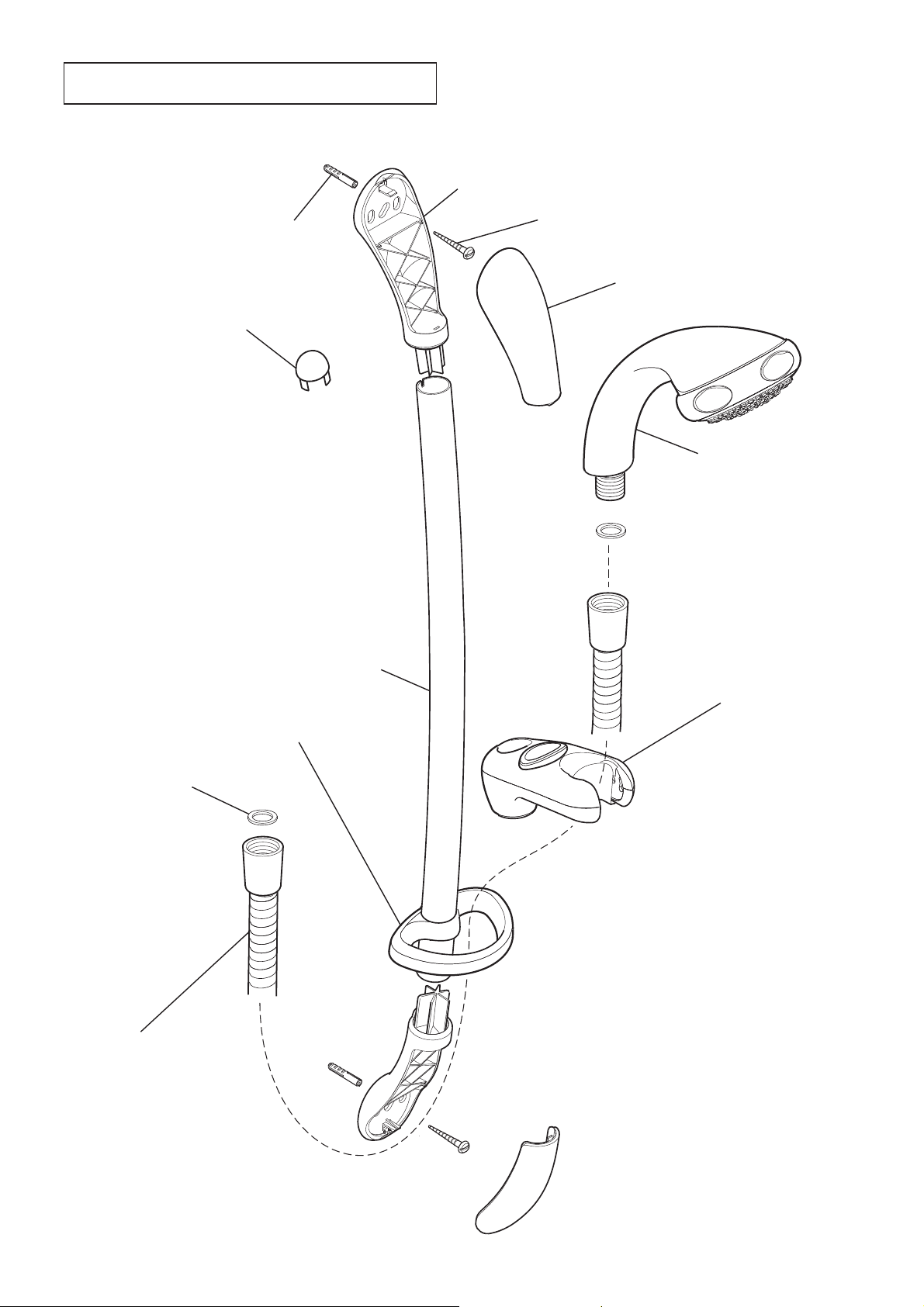
Mira Eco Shower Fittings
1. Decide on a suitable position for the slide bar
avoiding buried cables and pipes.
2. Important! The slide bar has an applicator
fi tted to one end to assist the assembly of
the slide bar through the clamp bracket (see
illustration). With the clamp bracket button
FULLY depressed carefully ease the slide
bar through the hole in the clamp bracket,
take care not to dislodge the constant friction
mechanism or friction pad.
3. Release the clamp bracket button. Remove
the applicator from the slide bar and store in
a safe place for future use.
4. Slide the hose retaining ring onto the slide bar
below the clamp bracket.
5. Make sure that the slots in the slide bar are
aligned with the lugs in the support and fi t the
two slide bar supports to the ends of the slide
bar. Make sure that each support is pushed
fi rmly home.
Note! If replacing an existing Mira Slide Bar
go to instruction 8.
6. Using the assembled slide bar and supports as
a template, mark the position of the two fi xing
holes using the centre slot.
Warning! Make sure that there are no buried
cables or pipes in the wall before drilling.
7. Drill the two 8 mm holes for the fixing
screws and insert the wall plugs supplied.
(Alternatively use proprietary cavity fi xings
for dry lined, stud partition, shower cubicle or
laminated panel walls).
8. Fix the bottom slide bar support to the wall
using the screw provided. Make sure that the
screw is fully tightened.
9. Loosely screw the top slide bar support to the
wall. Press fi rmly down on the top slide bar
support and, while continuing to apply force,
fully tighten the screw.
10. Fit the end caps to the slide bar supports.
11. Pass the flexible hose through the hose
retaining ring.
12. Screw the hose onto the showerhead and the
outlet of the shower control or RAC assembly
(Make sure the hose seals are fi tted) Do not
overtighten. Place the shower head into the
clamp bracket.
Clamp Bracket
Constant Friction
Mechanism and
Friction Pad
Applicator
Slide Bar
Wall Plug
Top Slide Bar Support
Fixing Screw
End Cap
Slide Bar
Clamp Bracket
Assembly
600
Hose Retaining
Ring
Slide Bar
Support Lug
Bottom Slide Bar
Support
End Cap
8
Page 9

OPERATION
Changing the Spray Setting
The showerhead spray head has four different
spray actions:- Start, Soothe and Force.
1. Start
Turn the spray plate anticlockwise until it
‘clicks’ (one click from the eco setting). Water
will fl ow from the outer set of holes.
2. Soothe
Turn the spray plate anticlockwise until it
‘clicks’ (two clicks from the eco setting). W ater
will fl ow from the large diameter holes.
3. Force
Turn the spray plate anticlockwise until it
‘clicks’ (three clicks from the eco setting).
Water will fl ow from the inner set of holes.
Height and Direction Adjustment
Release Button
9
Page 10

USER MAINTENANCE
If you require a Mira trained service engineer or
agent, refer to section: ‘Customer Services’.
Fault Diagnosis
Symptom:
•
No flow or low flow rate from shower
fi ttings.
Cause / Rectifi cation:
•
Spray plate blocked, clean or renew.
Make sure that the hose is not blocked or •
twisted.
Head of water below minimum required (Min
•
supply pressure 0.5 Bar)
Problem with the shower control, refer to your
•
shower control installation and user guide.
—————————————
Cleaning
Many household cleaners contain abrasives and
chemical substances, and should not be used for
cleaning plated or plastic fi ttings.
These fi nishes should be cleaned with a mild
washing up detergent or soap solution, and then
wiped dry using a soft cloth.
Use your thumb or a soft cloth to wipe any
limescale from the soft nozzles and the front
surface of the showerhead spray plate.
Important! The spray plate must be regularly
cleaned to make sure that the showerhead does
not become blocked.
Symptom:
•
Drip from the showerhead.
Cause / Rectifi cation:
•
A small amount of water may be retained in
the showerhead after the shower control has
been turned off. This is quite normal, changing
the angle of the showerhead may vary the
draining time.
Problem with the shower control, refer to your
•
shower control installation and user guide.
—————————————
Symptom:
•
Shower temperature changes when spray
action is adjusted.
Cause / Rectifi cation:
•
Adjusting the spray action changes the fl ow of
water. This may affect some shower controls
and plumbing installations. To minimise
the effect make sure that the spray plate is
clean.
Spray Plate Assembly - Internal
1. Remove the spray plate assembly.
2. Clean all the components with a stiff brush.
If necessary use a plastic kettle descalent
in accordance with the manufacturer's
instructions. Flush thoroughly with water
before the shower is used.
3. If necessary replace the 'O' seals. Refer to
section: Spare Parts.
4. Refi t the components in reverse order . Make
sure that the 'O' seals and the inner and outer
nozzle retaining rings are fi tted correctly.
Showerhead
Body
Outer Nozzle
Ring Retainer
Adjuster Ring
10
'O' Seals
Inner Nozzle
Ring Retainer
Spray Plate
Assembly
Page 11

SPARE PARTS
450.10
Slide Bar White
450.28
Slide Bar Chrome
450.21
Right Angle Connector
White
450.22
Right Angle Connector
Chrome
450.17
Slide Bar Wall Fixing Pack
1668.026
Adjustable Showerhead
(White)
1668.025
Adjustable Showerhead
(Chrome)
450.08
Seal Pack
450.20
Right Angle
Connector Pack
632.73
Hose Seal (x2)
450.01
Hose 1.25m Chrome
450.02
Hose 1.25m White
464.11
Hose 1.75 Chrome
1668.029
Spray Plate Pack
(Chrome)
1668.030
Spray Plate Pack
(White)
450.13
Adjuster Ring White
450.13
Adjuster Ring Chrome
450.24
Clamp Bracket (chrome)
450.16
Clamp Bracket (white)
450.30
Hose Retaining Ring (chrome)
450.11
Hose Retaining Ring (white)
450.26
Slide Bar Support Assembly White
450.27
Slide Bar Support Assembly Chrome
11
Page 12

5
+
!
3
CUSTOMER SERVICE
Guarantee of Quality
Mira Showers guarantee your shower fi ttings against any
defect in materials or workmanship for a period of one year
from the date of purchase.
Alternatively, to confi rm the applicable guarantee period
please contact Customer Services.
To validate the guarantee, please return your completed
registration card.
Within the guarantee period we will resolve defects, free
of charge, by repairing or replacing parts or modules as
we may choose.
T o be free of charge, service work must only be undertaken
by Mira Showers or our approved agents.
Service under this guarantee does not affect the expiry
date.
The guarantee on any exchanged parts or product ends
when the normal product guarantee period expires.
Not covered by this guarantee:
Damage or defects arising from incorrect installation,
improper use or lack of maintenance, including build-up
of limescale.
Damage or defects if the product is taken apart, repaired or
modifi ed by any persons not authorised by Mira Showers
or our approved agents.
This guarantee is in addition to your statutory and other
legal rights.
What to do if something goes wrong
If when you first use your shower, it doesn’t function
correctly , fi rst contact your installer to check that installation
and commissioning are satisfactory and in accordance with
the instructions in this manual. We are on hand to offer you
or your installer any advice you may need.
Should this not resolve the diffi culty, simply contact our
Customer Services Team who will give every assistance
and, if necessary, arrange for our service engineer to
visit. If the performance of your shower declines, consult
this manual to see whether simple home maintenance is
required. Please call our Customer Services Team to talk
the diffi culty through, request a service under guarantee
if applicable, or take advantage of our comprehensive
After-Sales service.
As part of our quality and training programme calls may be
recorded or monitored.
Our Customer Services T eam is comprehensively trained to
provide every assistance you may need: help and advice,
spare parts or a service visit.
Spare Parts
We maintain an extensive stock of spares and aim to provide
support throughout the product’s expected life.
Spares can be purchased from approved stockists or
merchants (locations on request) or direct from Customer
Services.
Spares direct will normally be despatched within two working
days. Payment can be made by Visa or MasterCard at the
time of ordering. Should payment by cheque be preferred,
a pro-forma invoice will be sent.
All spares are guaranteed for 12 months from date of
purchase. Spares that have been supplied directly from us
can be returned within one month from date of purchase,
providing that they are in good order and the packaging
is unopened.
Note! Returned spares will be subject to a 15% restocking
charge and authorisation must be obtained before return.
Please contact our Customer Services Team.
Note! In the interests of safety, spares requiring exposure
to mains voltages can only be sent to competent persons.
Service
Our Service Force is available to provide a quality service
at a reasonable cost. Y ou will have the assurance of a Mira
trained engineer/agent, genuine Mira spare parts and a
12 month guarantee on the repair.
Payment should be made directly to the engineer/agent
using Visa, MasterCard or a cheque supported by a
banker’s card.
To Contact Us
England, Scotland, Wales and Northern Ireland
Mira Showers Customer Services
Telephone: 0870 241 0888, Mon to Fri 8:00 am - 5:30 pm
Sat 8:30 am - 3:30 pm
E-mail: technical@mirashowers.com
Fax: 01242 282595
By Post: Cromwell Road, Cheltenham,
Gloucestershire, GL52 5EP
Eire
Modern Plant Ltd (Dublin)
Telephone: 01 459 1344, Mon to Fri 9:00 am - 5:00 pm
E-mail: sales@modernplant.ie
Fax: Dublin 01 459 2329
Post: Otter House, Naas Road,
Clondalkin, Dublin 22
Modern Plant (Cork)
Telephone: 021 496 8755, Mon to Fri 9:00 am - 5:00 pm
E-mail: cork@modernplant.ie
Fax: 021 496 8607
Post: Tramore Road, Cork
Mira is a registered trade mark of
Kohler Mira Limited.
The company reserves the right to alter
product specifi cations without notice.
www.mirashowers.com
!
1096015-W2-A (L97F) © Kohler Mira Limited, February 2008
12
Page 13

Check out our full range of Showers
Electric Showers
Digital Showers
Mixer Showers
Power Showers
Smart Showers
Shower Towers
From Top Shower Brands
Mira Showers
Aqualisa Showers
Triton Showers
Gainsborough Showers
Shower Pumps can upgrade your showering experience even more
Stuart Turner Shower Pumps
Salamander Shower Pumps
Grundfos Shower Pumps
 Loading...