

Page 1

Mira Atom ERD
With Moxie
These instructions must be left with the user
Installation & User Guide
1
For SPARES, ADVICE
or REPAIRS
Please call us on
0844 571 5000
(UK Only)
1232447-W2-A
Page 2
INTRODUCTION
Thank you for purchasing a quality Mira product. To enjoy the full potential of your new
product, please take time to read this guide thoroughly, having done so, keep it handy for
future reference.
GUARANTEE
For domestic installations, Mira Showers guarantee the Mira Atom against any defect in
materials or workmanship for a period of ve years from the date of purchase (shower ttings
and Moxie speaker for one year).
For non-domestic installations, Mira Showers guarantee the Mira Atom against any defect
in materials or workmanship for a period of one year from the date of purchase.
For terms and conditions refer to the back cover of this guide.
DESIGN REGISTRATION AND PATENTS
Design Registration GB 001225254-0003
Patents: GB 2 407 138
RECOMMENDED USAGE
Recommended Usage
Domestic
Light Commercial
Heavy Commercial
Healthcare
SAFETY : WARNINGS
WARNING - This product can deliver scalding temperatures if not operated, installed
or maintained in accordance with the instructions, warnings and cautions contained
in this guide.
The function of a thermostatic mixing valve is to deliver water consistently at a safe temperature.
In keeping with every other mechanism, it cannot be considered as functionally infallible and
as such, cannot totally replace a supervisor’s vigilance where that is necessary. Provided it is
installed, commissioned, operated and maintained within manufacturers recommendations,
the risk of failure, if not eliminated, is reduced to the minimum achievable.
1232447-W2-A
2
Page 3

WARNING - This product can deliver scalding temperatures if not operated, installed
or maintained in accordance with the instructions, warnings and cautions contained
in this guide.
The function of a thermostatic mixing valve is to deliver water consistently at a safe temperature.
In keeping with every other mechanism, it cannot be considered as functionally infallible and
as such, cannot totally replace a supervisor’s vigilance where that is necessary. Provided it is
installed, commissioned, operated and maintained within manufacturers recommendations,
the risk of failure, if not eliminated, is reduced to the minimum achievable.
Mira thermostatic mixers are precision engineered and should give continued safe and
controlled performance, provided:
1. They are installed, commissioned, operated and maintained in accordance with the
manufacturer’s recommendations.
2. Periodic attention is given, when necessary, to maintain the product in good functional
order.
Caution!
1. Read all of these instructions and retain this guide for later use.
2. Installation must be carried out in accordance with these instructions, and must be
conducted by designated, qualied and competent personnel.
3. Pass on this guide in the event of change of ownership of the installation site.
4. Follow all warnings, cautions and instructions contained in this guide.
5. Make sure that you fully understand how to operate this shower before use, read all
operating instructions and retain this guide for future reference.
6. This product is not intended for use by persons (including children) with reduced physical,
sensory or mental capabilities, or lack of experience and knowledge, unless they have
been given supervision or instruction concerning the use of the product by a person
responsible for their safety.
7. Children should be supervised to ensure that they do not play with the product.
8. DO NOT perform any unspecied modications to the shower or its accessories. When
servicing only use genuine Kohler Mira replacement parts.
9. DO NOT t any form of outlet ow control. Only Mira recommended outlet ttings should
be used.
10. DO NOT operate the temperature control rapidly, allow 10 – 15 seconds for the
temperature to stabilise before use.
11. Care is required when adjusting ow or temperature, make sure that the temperature
has stabilised.
12. Care is required if the product is turned off and back on during showering as this may
result in unstable temperature. Ensure temperature has stabilised before re-using
product.
13. Sunburn or skin conditions can increase your sensitivity to hot water. Make sure that
you set the shower to a cooler temperature.
14. The water supplies to this product must be isolated if the product is not to be used for
a long period of time. If the product or pipework is at risk of freezing during this period
they should also be drained of water.
15. When this product has reached the end of its serviceable life, it should be disposed of
in a safe manner, in accordance with current local authority recycling, or waste disposal
policy.
3
1232447-W2-A
Page 4

16. This wireless speaker complies with CE directives.
17. To play your personal music les, you need a wireless
BLUETOOTH® device.
18. This device is rated to IPX4.
19. Check local regulations for proper disposal.
20. DO NOT submerge the wireless speaker.
21. DO NOT spray water directly into the speaker.
22. The wireless speaker and battery are rated to operate in temperatures up to 140°F
(60°C). DO NOT expose to heat sources or install in any location where the temperature
may exceed 140°F (60°C).
23. DO NOT expose batteries to sunlight, re or other forms of excessive heat.
The BLUETOOTH® word mark and logos are registered trademarks owned by Bluetooth
SIG, Inc. and any use of such marks by Kohler Co. is under license. Other trademarks
and trade names are those of their respective owners.
CE Radiation Exposure Statement for Mobile Devices
This equipment complies with CE radiation exposure limits set forth for an uncontrolled
environment. This equipment should be installed and operated with a minimum distance
of 200 mm between the radiator and your body. The transmitter must not be co-located or
operating in conjunction with any other antenna or transmitter.
SPECIFICATIONS
Bar Valve Specication
Pressures
Maximum Static Pressure 10 Bar
Maximum Maintained Pressure 5 Bar
Minimum Maintained Pressure (Gas Water
Heater)
Minimum Maintained Pressure (Gravity
System)
Connections
Hot - Left 1/2" BSP to pipework, 3/4" BSP to valve
Cold - Right 1/2" BSP to pipework, 3/4" BSP to valve
Outlet - Bottom 1/2" BSP Male to exible hose
Note! This product does not allow for reversed inlets and will deliver unstable temperatures if tted
incorrectly.
Thermostatic Shut-down
For safety and comfort the thermostat will shut off the mixing valve within 2 Seconds if either supply
fails (achieved only if the blend temperature has a minimum differential of 12°C from either supply
temperature).
Temperatures
Close temperature control is provided
between
Optimum Thermostatic Control Range 35°C to 45°C (achieved with supplies of 15°C cold, 65°C
1232447-W2-A
1.0 Bar (for optimum performance supplies should be
nominally equal)
0.1 Bar (0.1 bar = 1 Metre head from cold tank base to
shower handset outlet)
20°C and 50°C
hot and nominally equal pressures).
4
Page 5
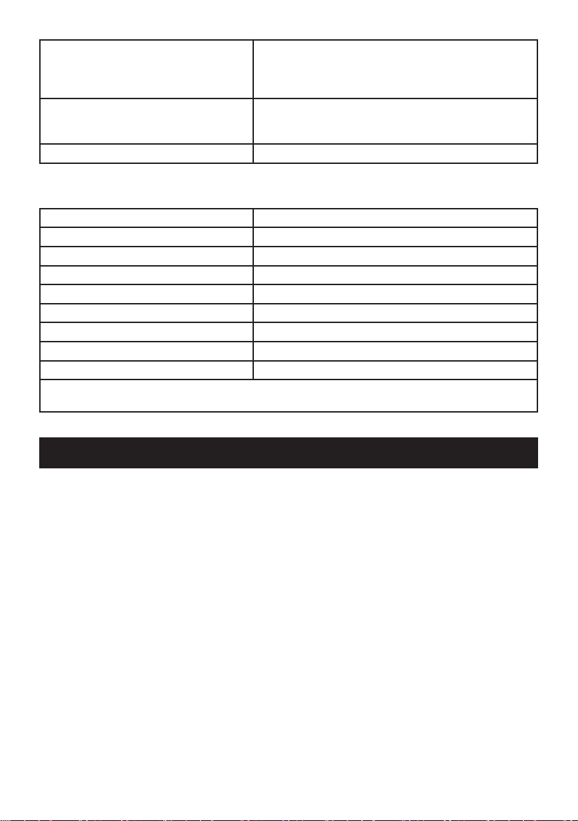
Recommended Hot Supply 0°C to 65°C (Note! The mixing valve can operate at
Minimum Recommended Differential
between Hot Supply and Outlet
Temperature
Minimum hot water supply temperature 55°C.
temperatures up to 85°C for short periods without damage.
However for safety reasons it is recommended that the
maximum hot water temperature is limited to 65°C).
12°C at desired ow rates.
Wireless Speaker Specication
Operating Temperature 0°C - 60°C
Maximum Relative Humidity 100% condensing
USB Cable Length 1 m
Output Power 1.5 Watts into 4 Ohms
Total Harmonic Distortion <1% at 1 kHz full output power
BLUETOOTH® wireless range 10 m
Battery Charge Time 7 hours
Play Time* 7 hours
Charge Voltage USB 5 V
*Actual battery life will vary with use,settings and environmental conditions. Rechargeable batteries
have a limited number of charge cycles.
INSTALLATION
Suitable Plumbing Systems
Gravity Fed:
The thermostatic mixer must be fed from a cold water cistern (usually tted in the loft space) and
a hot water cylinder (usually tted in the airing cupboard) providing nominally equal pressures.
Gas Heated System:
The thermostatic mixer can be installed with a combination boiler.
Unvented Mains Pressure System:
The thermostatic mixer can be installed with an unvented, stored hot water system.
Mains Pressurised Instantaneous Hot Water System:
The thermostatic mixer can be installed with systems of this type with balanced pressures.
Pumped System:
The thermostatic mixer can be installed with an inlet pump (twin impeller). The pump must
be installed on the oor next to the hot water cylinder.
5
1232447-W2-A
Page 6

General
Installation must be carried out in accordance with these instructions, and must be conducted
by designated, qualied and competent personnel.
The installation must comply with the “Water Supply Regulations 1999 (Water Fittings)” or any
particular regulations and practices, specied by the local water company or water undertakers.
Note! Make sure that all site requirements correspond to the information given in section:
‘Specications’.
1. The product must not be installed in an area where it may freeze. Pipework to the product
that could become frozen must be properly insulated.
2. Do not install the product in a position in which service access is restricted.
3. For stud partitions alternative xings may be required.
4. Isolating valves must be installed close to the product for ease of maintenance.
5. Pipework must be rigidly supported and avoid any strain on the connections.
6. Pipework dead-legs should be kept to a minimum.
7. If pipework enters the product from the rear through a hole in the wall, provision must
be made to prevent water ingress back into the wall structure.
8. The position of the shower and shower ttings must provide a minimum gap of 25 mm
between the showerhead and the spill over level of any bath, shower tray or basin and
a minimum gap of 30 mm between the showerhead and the spill over level of any toilet,
bidet or other appliance with a Fluid Category 5 backow risk (see diagram).
9. The showerhead should be positioned
so that it discharges down the centre
line of the bath or across the opening
Mixer Shower
Zone of
Backow Risk
of a shower cubicle.
10. Only use the inlet connections supplied
with the product. DO NOT use any
other type of ttings.
11. All pipework must be checked for
leaks before the product installation
is completed. The product should
be pressurised & the inlet & outlet
connections inspected.
12. DO NOT overtighten connections,
screws or grubscrews as product
damage may occur.
13. Upon completion of installation, or if the
30 mm
Minimum
25 mm
Minimum
25 mm
Minimum
product is dismantled during installation
or servicing, then the product must be
Toilet or Bidet
FC5
Bath or Shower
Tray FC3
Hand Basin
FC3
inspected to ensure that there are no
leaks.
14. Having completed the installation, make sure that the user is familiar with the operation
of the product.
1232447-W2-A
6
Page 7

Installation of the Bar Valve
Important! Before installing the pipework, please ensure that there is a minimum of
1065mm height clearance to allow for the rigid riser and overhead to be installed above.
If installing in a restricted height area, a shorter riser rail can be ordered as a spare part.
The thermostatic bar valve should be installed where it will be supported by xed pipework.
1. Install the pipework, making sure that it is set at the correct distance apart (150 ± 24 mm)
and solidly xed.
2. Apply suitable thread sealant (not supplied) and attach the offset connectors to the
pipework in the wall. The offset connectors must protrude between 40 and 43 mm from
the nished wall.
Note! Connections are: Hot-Left, Cold-Right. This is very important as this product
does not allow for reversed inlets.
1 2
½" BSP Female
Connection
40 - 43 mm
Offset
Connector
Apply Silicone
Sealant to seal
hole in wall
150 mm
Support Bracket
Tile
3 4
Spanner Flats
Tighten the offset connectors using a suitable
spanner. Make sure that the connectors are
level and set at the correct distance apart,
using the bar valve as a guide to spacing.
Screw the concealing plates onto the offset
connectors until they come into contact with
the wall.
7
Caution! Make sure that the supply pipework
is ushed before installing the Bar Valve.
Assemble the bar valve with a sealing
washer/lter in each inlet and attach to the
offset connectors.
Note! Connections are: Hot-Left,Cold-Right.
1232447-W2-A
Page 8

Installation of the Shower Fittings
1. Slide the hose retaining ring and the clamp bracket onto the middle bar, and then screw
the middle and lower bar sections together.
2. Screw the riser arm to the middle and lower bar section.
3. Push the riser bar into the top of the bar valve.
Note! The riser bar must be located correctly, push down rmly to seat it.
4. Insert the wall xing bracket into the riser arm mounting boss, then swivel the bar if
necessary to reposition the wall xing bracket against the wall.
Note! The grubscrew mounting hole must be positioned at the top.
5. Mark the holes for the wall xing bracket.
Note! Use a spirit level to ensure the bar is vertical.
6. Remove the wall xing bracket from the mounting boss then remove the riser bar from
the bar valve.
7. Drill two holes to suit the wall xings, ensuring that the bar valve is protected from debris.
Fix the bracket to the wall.
8. Ret the riser bar into the bar valve and then put the concealing cover onto the riser arm
mounting boss.
9. Push the riser arm mounting boss onto the wall xing bracket.
10. Fit and tighten the grubscrew (2.5 mm hexagonal key) into the hole on top of the mounting
boss then push the concealing cover over the wall xing bracket.
11. Tighten the grubscrew at the valve end and t the grubscrew cover.
12. Screw the xed shower head onto the riser arm. Make sure that the washer is tted.
Note! The Moxie wireless speaker does not have to be tted at this stage.
13. Fit the shower hose onto the bottom outlet of the bar valve.
Note! The shower hose has slightly different sized conical connections at each end (the
smaller diameter / longer length conical is identied with a Red protective cover or a
White label). The end with the red cover or white label connects to the showerhead, the
clear end connects to the valve.
14. Push the shower hose through the retaining ring and screw it to the showerhead.
15. Place the showerhead into the clamp bracket, adjusting the angle and height to the users
preference.
1232447-W2-A
8
Page 9

Mounting
Boss
Wall Fixing Bracket
Grub Screw
Riser Arm
Fixed
Showerhead
Wall Fixing
Bracket
Concealing
Cover
Riser
Arm
Clamp Bracket
Hose
Note! 'O' Seal
is located inside
Lower Bar
Valve Grub
Screw
Middle Bar
Showerhead
Hose Retaining Ring
Lower Bar
9
1232447-W2-A
Page 10

COMMISSIONING
Bar Valve Commissioning
Maximum Temperature Setting
Before using the shower, the maximum temperature must be checked to make sure that it is
at a safe level. It has been preset to a safe showering temperature under ideal conditions at
the factory, appropriate for most systems. However, site conditions and personal preference
may make it necessary to reset this temperature.
Note! Make sure that the hot water temperature is at least 55°C and that there is sufcient
supply.
Caution! Before testing the mixer, make sure that the hot and cold water is owing correctly
by exercising the temperature selector knob between the cold and hot stops.
1. Turn the temperature selector knob anticlockwise until it stops and test that the
temperature of the water from the shower outlet is hot enough.
2. If not, depress the override button and carefully rotate the knob further. If the water
temperature is still not hot enough complete the following procedure.
3. Rotate the temperature selector knob back to the override position.
4. Push in and rotate the concealing cap clockwise to remove. Remove the xing screw.
5. Pull off the temperature selector knob without disturbing the stop assembly.
6. Replace the temperature selector knob so that the lever is the 1 O'clock position.
7. Rotate the temperature selector knob against the stop, wait for the water to stabilise
and test that the temperature of the water from the shower outlet is hot enough.
If the water temperature is still not hot enough repeat the procedure until a maximum
safe temperature is achieved at the override position.
8. Ret and tighten the xing screw, ret the concealing cap.
1232447-W2-A
Temperature
Selector Knob
Stop Assembly
Concealing Cap
Fixing Screw
Push in and
rotate to remove
10
Page 11

Wireless Speaker Pairing
1
If required set your BLUETOOTH® to ON.
Set your music device to midrange volume
before connecting to the wireless speaker
3 4
The light will blink blue to indicate pairing
mode. Pair with your BLUETOOTH® device.
If a password is required enter '0000'. The
light will turn solid blue when connected.
2
1 sec
Press the power button for 1 second to power
the wireless speaker ON or OFF.
Use the USB cable provided to recharge your
Moxie speaker. Always ensure the sealing
plug is re-tted before use.
Wireless Speaker LED Status
LED Status – Charging Mode
Red blink Battery is charging
Red Battery recharge is complete
LED Status – Operating Mode
Blue blink BLUETOOTH pairing mode
Blue Connected to a BLUETOOTH device
Blue/red blink Connected to a BLUETOOTH device. Battery is low
Note! If pairing is lost, the wireless speaker will power OFF after 90 seconds.
11
1232447-W2-A
Page 12

OPERATION
Bar Valve
Decrease
Temperature
Temperature
Override
Button
Increase
Temperature
Temperature
OFF
Flow Selector Knob
Adjusting the Temperature
The temperature is controlled by rotating the temperature selector knob.For safety reasons, the
temperature is limited by an override stop. To obtain a higher temperature, press the override
button on the temperature selector knob and continue to rotate the knob.
Adjusting the Flow
The ow is controlled by rotating the ow selector knob to either the overhead or showerhead
mode.
Wireless Speaker
The Moxie showerhead does not have to be stored in the xed showerhead. At the end of
your shower it can be removed and placed on the stand in your bathroom.
Turn on your music device and press play.
Turn on the Moxie speaker by pressing the ON
button for approximately 1 second.
Music will come out of the speaker.
Place the speaker in the showerhead.
Note! The speaker will be held in position by
magnets.
Enjoy your shower. At the end of your shower,
remove the speaker from the showerhead.
Press the button for approximately 1 second to
turn OFF
Place the speaker on the stand.
Selector Knob
1232447-W2-A
12
Page 13

FAULT DIAGNOSIS
If you require a Mira trained service engineer or agent, refer to section: ‘Customer Services’.
Bar Valve Fault Diagnosis
Symptom Cause Recommended Action
Water too hot or too
cold
Inlets reversed (hot supply to
cold supply).
Check lters for any blockage.
Rework inlet pipework.
Remove and clean lters.
Poor temperature
control
Fluctuating or
reduced ow
Water leaking from
the shower handset/
overhead
Check the maximum
temperature setting (If you
have a combination type
boiler it may not be producing
sufcient hot water at the
desired ow rate).
Installation conditions outside
operating parameters.
Make sure that the inlet
temperature differentials are
sufcient.
Check the shower handset,
hose and lters for any
blockage.
Make sure that the maintained
inlet pressures are nominally
balanced and sufcient.
Air lock or partial blockage in
the pipework.
Normal for a short period after
shut off.
Fit a ow regulator to the shower
valve outlet.
Refer to Specications and
Commissioning.
Refer to Specications.
Remove blockage.
Refer to Specications.
Remove blockage.
Check that the pressures are not
in excess of the specications
for this product.
Wireless Speaker Fault Diagnosis
Symptom Cause Recommended Action
After playing music
loudly, the music
stops even though
a song is properly
selected.
Thermal shutdown Shut down the system for 1 hour
to allow the unit to cool. Make sure
the area where the unit is installed
does not exceed 60°C.
13
1232447-W2-A
Page 14

Symptom Cause Recommended Action
The status LED is not
illuminated.
No sound plays
through the speaker..
Battery is not charged. Use the USB cable provided to
recharge the battery.
The song is paused.
Make sure the song is playing.
If the song is paused, press
the resume feature to continue
playback.
The wireless speaker
is not connecting to
my BLUETOOTH®
device.
LED does not blink
red when charging.
The volume is too low.
The BLUETOOTH device is not
within range.
The volume is too low.
The BLUETOOTH device is not
paired with the wireless speaker.
The BLUETOOTH requires
password entry for pairing.
USB connection to the wireless
speaker may be loose.
No power to the USB port.
CLEANING
Make sure the volume is turned up
high enough for proper enjoyment..
Make sure that the BLUETOOTH
device is within range of your
wireless speaker.
Make sure the volume is turned up
high enough for proper enjoyment.
Pair your BLUETOOTH device with
the wireless speaker according to
the pairing instructions for your
BLUETOOTH device.
Enter “0000” for the password.
Check the USB connection to the
wireless speaker and reconnect if
necessary.
Make sure there is power to the
USB cable
Cleaning
Many household cleaners contain abrasives and chemical substances, and should not be used
for cleaning plated or plastic ttings. These nishes should be cleaned with a mild washing
up detergent or soap solution, and then wiped dry using a soft cloth.
Important! The showerhead must be descaled regularly, keeping the showerhead clean
and free from limescale will ensure that your shower and showerhead continue to perform
to their maximum. A blocked showerhead can restrict the ow rate and may cause damage
to your shower.
The Moxie speaker must only be cleaned with a damp cloth and then wiped dry. Do not spray,
submerge or pour water into the speaker as product damage will occur.
1232447-W2-A
14
Page 15

1836.180
The note refers to the seal that is
fitted within the lower riser bar.
This seal is already in place
INSIDE the riser bar.
If it's missing please send out
4.1736.740
Z Connectors
1836.244
Flow Cartridge
Nut
1836.166
Flow Knob
Assembly
SPARE PARTS
1836.182
Riser Arm
1736.733
Wall Fixing
1736.732
Middle Bar
1836.171
Concealing Plates
1836.247
Plug
1836.174
Inlet Seal/
Filter
1836.170
Flow
Cartridge
1836.164
Temperature
Knob Assembly
1836.163
1744.108
Thermostatic
Cartridge
Cartridge
Nut
1736.735
Short Bar
A short bar can be ordered if
the ceiling height is not sufficient
for the standard bar length.
1740.599 Moxie Wireless Speaker
1703.203
Clamp Bracket
1703.199
Hose Retaining
Ring
150.58
Hose (1.25 M)
1736.734
Lower Bar
1740.601
Overhead - White/Chrome
(does not include Moxie Speaker)
1770.609
Multi Mode
Handset
632.73
Hose Seal (x2)
1192205-0
Sealing Plug
1191385
Charging Cable
15
1212765-0
Stand
1232447-W2-A
Page 16

CUSTOMER SERVICE
Guarantee
Your product has the benefit of our manufacturer’s
guarantee which starts from the date of purchase.
To activate this guarantee, please return your completed
registration card, visit our website or free phone 0800
0731248 within 30 days of purchase (UK only).
Within the guarantee period we will resolve defects in
materials or workmanship, free of charge, by repairing or
replacing parts or product as we may choose.
This guarantee is in addition to your statutory rights
and is subject to the following conditions:
● The guarantee applies solely to the original installation
under normal use and to the original purchaser only.
The product must be installed and maintained in
accordance with the instructions given in this user
guide.
● Servicing must only be undertaken by us or our
appointed representative. Note! if a service visit
is required the product must be fully installed and
connected to services.
● Repair under this guarantee does not extend the original
expiry date. The guarantee on any replacement
parts or product ends at the original expiry date.
● For shower fi ttings or consumable items we reserve
the right to supply replacement parts only.
The guarantee does not cover:
● Call out charges for non product faults (such as
damage or performance issues arising from incorrect
installation, improper use, inappropriate cleaning,
lack of maintenance, build up of limescale, frost
damage, corrosion, system debris or blocked fi lters)
or where no fault has been found with the product.
● Water or electrical supply, waste and isolation issues.
● Compensation for loss of use of the product or
consequential loss of any kind.
● Damage or defects caused if the product is repaired
or modifi ed by persons not authorised by us or our
appointed representative.
● Routine maintenance or replacement parts to
comply with the requirements of the TMV 2 or TMV
3 healthcare schemes.
● Accidental or wilful damage.
● Products purchased ex-showroom display.
What to do if something goes wrong
If your product does not work correctly refer to this
manual for fault diagnosis and check that it is installed
and commissioned in accordance with our instructions.
If this does not resolve the issue, contact us for help
and advice.
Extended Guarantees
A selection of protection plans are available that
enable you to cover repair bills (excludes Eire). Ring
01922 471763 for more details.
Helpdesk Service - Ring our Customer
Services Team for product advice, to purchase
spare parts or accessories or to set up service
visit. Yo u can contact us via phone or e-mail,
details below. Please provide your model
name, power rating (if applicable) and date
of purchase.
Mira Showers Website (www.mirashowers.
co.uk)
Visit our website to register your guarantee,
download user guides, diagnose faults,
purchase our full range of accessories and
popular spares, or request a service visit.
Spares and Accessories - We hold the largest
stocks of genuine Mira spares and accessories.
Contact us for a price or visit our website to
purchase items from our accessory range and
popular spares
Service/Repairs - No one knows our products
better than our nationwide team of Service
Technicians. We can carry out service or repair
work to your product both during and after the
guarantee period. Ask about our fi xed price
service repairs.
.
To Contact Us: UK
0844 571 5000
Fax: 01242 282595
E-mail: Visit www.mirashowers.co.uk/
contactus
Mira Customer Services Dept, Cromwell
Road, Cheltenham, Gloucestershire, GL52
5EP
To Contact Us: Eire Only
01 531 9337
E-mail: CustomerServiceEire@
mirashowers.com
Mira is a registered trade mark of
Kohler Mira Limited.
The company reserves the right to alter
product specifi cations without notice.
1232447-W2-A
16
FM 14648
© Kohler Mira Limited, February 2014
 Loading...