

Page 1
Service and Parts
Automatic Transfer Switches
Models:
M340+
Logic:
Microprocessor
U.S.A. Plant ISO Registered
TP-5672 11/95d
Page 2

Table of Contents
SUBJECT PAGE SUBJECT PAGE
Safety Precautions and Instructions I. . . . . . . . . . .
Introduction i. . . . . . . . . . . . . . . . . . . . . . . . . . . . . . . . .
List of Related Manuals i. . . . . . . . . . . . . . . . . . . . . . . .
Service Assistance i. . . . . . . . . . . . . . . . . . . . . . . . . . .
Section 1. Specifications 1-1. . . . . . . . . . . . . . . . . . .
Purpose of Switch 1-1. . . . . . . . . . . . . . . . . . . . . . . . . . .
Components of Switch 1-1. . . . . . . . . . . . . . . . . . . . . . .
Ratings 1-2. . . . . . . . . . . . . . . . . . . . . . . . . . . . . . . . . . . .
Interpreting a Transfer Switch Part Number 1-3. . . . .
Specifications 1-4.. . . . . . . . . . . . . . . . . . . . . . . . . . . . . .
Standard Features 1-4. . . . . . . . . . . . . . . . . . . . . . .
Shunt-Jumper-Controlled Accessories 1-5. . . . . .
Optional Features 1-5. . . . . . . . . . . . . . . . . . . . . . . .
Section 2. Operation 2-1. . . . . . . . . . . . . . . . . . . . . . .
LED Indicators 2-1. . . . . . . . . . . . . . . . . . . . . . . . . . . . . .
Control Switches and Indicators 2-2. . . . . . . . . . . . . . .
Sequence of Operation 2-3. . . . . . . . . . . . . . . . . . . . . . .
Normal Source Failure 2-3. . . . . . . . . . . . . . . . . . . .
Normal Source Restoration 2-4. . . . . . . . . . . . . . .
Sequence of Operation Programmed Transition 2-6.
Normal Source Failure 2-6. . . . . . . . . . . . . . . . . . . .
Normal Source Restoration 2-7. . . . . . . . . . . . . . .
To Disconnect The P1 Plug 2-9. . . . . . . . . . . . . . . . . . .
Electrical Operation Test 2-9. . . . . . . . . . . . . . . . . . . . .
Section 3. Troubleshooting Guide 3-1. . . . . . . . . .
Section 4. Controller Troubleshooting 4-1. . . . . .
Power to the System 4-2. . . . . . . . . . . . . . . . . . . . . . . . .
Keypad And Status Panel 4-3. . . . . . . . . . . . . . . . . . . .
Normal Source Voltage and Frequency 4-6.. . . . . . . .
Emergency Source Voltage and Frequency 4-9.. . . .
System-Status, Not-In-Automatic Error 4-11.. . . . . . .
System-Status, System-Alert 4-12. . . . . . . . . . . . . . . .
Contactor Position Fault Error Messages 4-12. . . . . .
Transfer Hang Error Message 4-12. . . . . . . . . . . . . . . .
Power-Down Error Message 4-12. . . . . . . . . . . . . . . . .
RAM Or Memory Error Message 4-13. . . . . . . . . . . . .
Manual Transfer Message 4-13. . . . . . . . . . . . . . . . . . .
Manual-to-Off Transfer Message 4-13.. . . . . . . . . . . .
Fault #1 Or Fault #2 Message 4-14.. . . . . . . . . . . . . . .
Programming Mode Not-In-Off 4-15. . . . . . . . . . . . . . .
Engine Operates When it Should Not 4-16. . . . . . . . .
Engine Will Not Start 4-18.. . . . . . . . . . . . . . . . . . . . . . .
Area Protection 4-20. . . . . . . . . . . . . . . . . . . . . . . . . . . .
Shunt Jumper-Controlled Options 4-21. . . . . . . . . . . . .
Inphase Monitor 4-23. . . . . . . . . . . . . . . . . . . . . . . . . . . .
Source Monitors 4-24. . . . . . . . . . . . . . . . . . . . . . . . . . . .
Plant Exerciser 4-27. . . . . . . . . . . . . . . . . . . . . . . . . . . . .
Time Delays 4-32. . . . . . . . . . . . . . . . . . . . . . . . . . . . . . .
Manual Override 4-33. . . . . . . . . . . . . . . . . . . . . . . . . . .
Off Delays 4-34. . . . . . . . . . . . . . . . . . . . . . . . . . . . . . . . .
Section 5. Accessory Troubleshooting 5-1. . . . . .
Optional Accessories 5-2. . . . . . . . . . . . . . . . . . . . . . . .
Emergency Source Three-Phase Phase Option 5-2.
Test Switches 5-4.. . . . . . . . . . . . . . . . . . . . . . . . . . . . . .
Time Delay Override Option 5-10. . . . . . . . . . . . . . . . .
Preferred Source Switch 5-14.. . . . . . . . . . . . . . . . . . .
Relay Auxiliary Dry Contacts 5-15. . . . . . . . . . . . . . . . .
Main Shaft Auxiliary Dry Contacts 5-22. . . . . . . . . . . .
Meters 5-23. . . . . . . . . . . . . . . . . . . . . . . . . . . . . . . . . . . .
Battery Charger 5-47. . . . . . . . . . . . . . . . . . . . . . . . . . . .
Manual Operation Switches 5-54. . . . . . . . . . . . . . . . . .
Load Shedding Contacts 5-63. . . . . . . . . . . . . . . . . . . .
Remote Communication—RS/232 Or RS/485 5-65. .
Section 6. Service Parts 6-1. . . . . . . . . . . . . . . . . . . .
Introduction 6-1. . . . . . . . . . . . . . . . . . . . . . . . . . . . . . . . .
Inner Panel 6-2. . . . . . . . . . . . . . . . . . . . . . . . . . . . . . . . .
Accessories 6-5. . . . . . . . . . . . . . . . . . . . . . . . . . . . . . . .
Time Delay 6-5. . . . . . . . . . . . . . . . . . . . . . . . . . . . . . . . .
Source monitors 6-5. . . . . . . . . . . . . . . . . . . . . . . . . . . . .
Test Switches 6-5.. . . . . . . . . . . . . . . . . . . . . . . . . . . . . .
Time Delay Override Switches 6-5.. . . . . . . . . . . . . . .
Preferred-Source Switches 6-5. . . . . . . . . . . . . . . . . . .
Auxiliary Contacts—Relay 6-5. . . . . . . . . . . . . . . . . . . .
Auxiliary Contacts—Main Shaft 6-5. . . . . . . . . . . . . . . .
Meters 6-6. . . . . . . . . . . . . . . . . . . . . . . . . . . . . . . . . . . . .
Plant Exercisers 6-11. . . . . . . . . . . . . . . . . . . . . . . . . . . .
Battery Chargers 6-11. . . . . . . . . . . . . . . . . . . . . . . . . . .
Source Monitors—Normal and Emergency 6-12. . . .
Load-Shed Contacts 6-12.. . . . . . . . . . . . . . . . . . . . . . .
Time Delays 6-12. . . . . . . . . . . . . . . . . . . . . . . . . . . . . . .
Appendix A. Glossary of Abbreviations A-1.. . . .
Appendix B. General Controller Information B-1.
Appendix C. Commonly Used Accessories C-1. .
Page 3

Safety Precautions and Instructions
A transfer switch, like any other electromechanical
device, can pose potential dangers to life and limb if
improperly maintained or imprudently operated. The
best way to prevent accidents is to be aware of the
potential dangers and to always use good common
sense. Below are some general precautions relating to
theoperation ofa transfer switch. This manual contains
several types of safety precautions which are explained
below. SAVE THESE INSTRUCTIONS.
DANGER
Danger indicates the presence of a hazard that will
cause severe personal injury, death, or substantial
property damage if the danger is ignored.
WARNING
Warning indicates the presence of a hazard that can
cause severe personal injury, death, or substantial
property damage if the warning is ignored.
NOTE
Note communicates installation, operation, or
maintenance information that is important but not
hazard related.
Safety decals are affixed to the generator set in
prominent places to advise the operator or service
technician of potential hazards. The decals are
reproduced here to improve operator recognition. For a
further explanation of decal information, refer to the
safety precautions throughout this manual. Before
operating or servicing the generator set, be sure you
understand the messages of these decals. Replace
decals if missing or damaged.
Safety decals are affixed to the transfer switch in
prominent places to advise the operator or service
technician of potential hazards. The decals are
reproduced here to improve operator recognition. For a
further explanation of decal information, refer to the
safety precautions throughout this manual. Before
operating or servicing the transfer switch, be sure you
understand the messages of these decals. Replace
decals if missing or damaged.
CAUTION
Caution indicates the presence of a hazard that will or
can cause minor personal injury or property damage if
the caution is ignored.
TP-5672 11/95
Safety Precautions and Instructions I
Page 4

Accidental Starting
WARNING
Accidental starting.
Can cause severe injury or death.
Disconnect battery cables before working on
generator set (negative lead first and reconnect it
last).
Accidental starting can cause severe injury or
death. Turn generator set master switch to OFF
position, disconnect power to battery charger, and
remove battery cables (remove negative lead first and
reconnectitlast)to disable generator setbeforeworking
on any equipment connected to generator set. The
generator set can be started by automatic transfer
switch or remote start/stop switch unless these
precautions are followed.
II Safety Precautions and Instructions TP-5672 11/95
Page 5
Battery
WARNING
Sulfuric acid in batteries.
Can cause severe injury or death.
Use protective goggles and clothes. Battery acid can
cause permanent damage to eyes, burn skin, and eat
holes in clothing.
WARNING
Explosion.
Can cause severe injury or death. Relays in
battery charger cause arcs or sparks.
Locate in a well-ventilated area. Keep explosive
fumes away.
Sulfuric acid in batteries can cause severe injury or
death. Sulfuric acid in battery can cause permanent
damage to eyes, burn skin, and eat holes in clothing.
Alwayswear splash-proofsafety goggleswhen working
around the battery. If battery electrolyte is splashed in
the eyes or on skin, immediately flush the affected area
for15 minutes withlargequantities of cleanwater. Seek
immediatemedicalaidin the caseofeyecontact. Never
addacidtoa battery once thebatteryhasbeen placed in
service. This may result in hazardous spattering of
electrolyte.
Sulfuric acid in batteries can cause severe injury or
death. Sulfuric acid in battery can cause permanent
damage to eyes, burn skin, and eat holes in clothing.
Alwayswear splash-proofsafety goggleswhen working
around the battery. If battery electrolyte is splashed in
the eyes or on skin, immediately flush the affected area
with large quantities of clean water. Continue flushing
with water until emergency help arrives Seek
immediatemedicalaidin the caseofeyecontact. Never
addacidtoa battery once thebatteryhasbeen placed in
service. This may result in hazardous spattering of
electrolyte.
Explosioncancause severe injury or death. Battery
gases can cause an explosion. Do not smoke or permit
flame or spark to occur near a battery at any time,
particularly when it is being charged. Avoid contacting
terminals with tools, etc., to prevent burns and sparks
that could cause an explosion. Remove wristwatch,
rings, and any other jewelry before handling battery.
Never connect negative (--) battery cable to positive (+)
connection terminal of starter solenoid. Do not test
batterycondition by shortingterminals together. Sparks
could ignite battery gases or fuel vapors. Ventilate any
compartment containing batteries to prevent
accumulation of explosive gases. To avoid sparks, do
not disturb battery charger connections while battery is
being changed. Always turn battery charger off before
disconnecting battery connections. Remove negative
lead first and reconnect it last when disconnecting
battery.
TP-5672 11/95
Safety Precautions and Instructions III
Page 6

Hazardous Voltage/
Electrical Shock
DANGER
Hazardous voltage.
Will cause severe injury or death.
Do not open enclosure until all power sources are
disconnected.
(600 Volt and above)
DANGER
Hazardous voltage.
Will cause severe injury or death.
Disconnect power sources before servicing.
Barrier must be installed after adjustments,
maintenance, or servicing.
(600 Volt and above)
WARNING
WARNING
Hazardous voltage.
Can cause severe injury or death.
Do not open enclosure until all power sources are
disconnected.
(under 600 Volt)
Hazardous voltage can cause severe injury or
death. Whenever electricity is present, there is the
hazardofelectrocution. Openmaincircuitbreaker on all
power sources before servicing equipment. Electrically
ground the generator set and electrical circuits when in
use. Never come into contact with electrical leads or
appliances when standing in water oron wet ground, as
the chance of electrocution is increased under such
conditions.
Hazardous voltage can cause severe injury or
death. Short circuits can cause bodily injury and/or
equipment damage. Do not contact electrical
connections with tools or jewelry while adjustments are
made. Remove wristwatch, rings, and jewelry that can
cause short circuits.
Hazardous voltage can cause severe injury or
death. To prevent the possibility of electrical shock,
disconnect harness plug before installing any
accessories involving connection to transformer
assembly primary terminals 76, 77, 78, and 79.
Terminals are at line voltage!
(S340, R340, and R33 models only.)
Hazardous voltage can cause severe injury or
Hazardous voltage.
Can cause severe injury or death.
Disconnect power sources before servicing.
Barrier must be installed after adjustments,
maintenance, or servicing.
(under 600 Volt)
IV Safety Precautions and Instructions TP-5672 11/95
death. To prevent the possibility of electrical shock,
disconnect harness plug before installing any
accessories involving connection to transformer
assembly primary terminals on microprocessor logic
models. Terminals are at line voltage!
Page 7

Hazardous voltage can cause severe injury or
death. To prevent the possibility of electrical shock,
de-energize the normal power source to be connected
to the transfer switch before makingany line or auxiliary
connections.
Hazardous voltage can cause severe injury or
death. De-energize bothnormal and emergencypower
sourcesbefore proceeding. Movegenerator set master
switch on controller to OFF position and disconnect
battery negative (--) before working on transfer switch!
Turn the transfer switch selector switch to the OFF
position.
Hazardous voltage can cause severe injury or
death. Disconnect inner panel harness at in-line
connector. This will de-energize circuit board and logic
circuitry, but allow transfer switch to continue to supply
utility power to necessary lighting and equipment.
Hazardousvoltage will exist ifanyaccessories mounted
to inner panel are NOT wired through the inner panel
harness and de-energized by in-line connector
separation. Such accessories are at line voltage.
TP-5672 11/95
Safety Precautions and Instructions V
Page 8

Heavy Equipment
WARNING
Unbalanced weight.
Improper lift can cause severe injury or death
and/or equipment damage.
Use adequate lifting capacity.
Never leave transfer switch standing upright
unless it is securely bolted in place or stabilized.
VI Safety Precautions and Instructions TP-5672 11/95
Page 9

Notes
NOTE
Hardware Damage! Transfer switch may use both
American standard and metric hardware. Use the
correct size tools to prevent rounding of bolt heads and
nuts.
NOTE
When replacing hardware, do not substitute with
inferior grade hardware. Screws and nuts are
available in different hardness ratings. American
Standard hardware uses a series of markings and
metric hardware uses a numeric system to indicate
hardness. Check markings on bolt head and nuts for
identification.
NOTE
A manual operator handle is provided on the transfer
switch for maintenance purposes only. Return the
transfer switch to the normal position. Remove manual
operator handle (if used) and store it on the transfer
switch in the placeprovided when service is completed.
NOTE
Perform voltage checks in the order given to avoid
damaging the switch.
NOTE
These battery chargers are designed strictly for use in
thistransfer switch andconform with ULand CSAlisting
requirements where specified. Do not use battery
charger before reading instructions.
NOTE
Connect source and load phases as indicated by the
markings and drawings. Improper connections may
causeshortcircuitsand can causephase-sensitiveload
devices to run in reverse or prevent load devices from
functioning.
NOTE
Charger Damage! Connect battery charger only to a
batterywith thesame DC voltage as the battery charger
output rating.
NOTE
Covertransferswitchduring installation to keepdirt,grit,
metal drill chips, etc., out of components. Cover
solenoid mechanism during installation. After
installation, use manual operating handle to position
contactor to ensure that it operates freely. Do not use a
screwdriver to force contactor mechanism.
TP-5672 11/95
Safety Precautions and Instructions VII
Page 10

Introduction
This manual covers the operation, troubleshooting,
repair,and service parts for the M340+ microprocessor
logic controller.
Read through this manual and carefully follow all
procedures and safety precautions to ensure proper
transferswitchoperationandtoavoidbodilyinjury.Keep
this manual with the transfer switchfor futurereference.
Service requirements are minimal but are very
important to the safe and reliable operation of the
transfer switch; therefore, inspect associated parts
often. It is recommended that an authorized service
distributor perform required servicing to keep the switch
in top condition.
All information found in this publication isbased on data
availableat timeof printing. The manufacturerreserves
the right to make changes to this literature and the
products represented at any time without notice and
without incurring obligation.
List of Related Manuals
The logic controller covered in this manual is part of a
family of related devices. Separate service and parts
manuals are available for each group within the overall
family. Be sure this manual is the correct manual for the
automatic transfer switch.
A power conversion unit is included in each automatic
transfer switch. There are three types of power
conversion units and each type is covered in a separate
service and parts manual. Available power conversion
units and the related manual numbers are as follows:
Service/
Power Switch Device
Mechanically held or
electrically held contactors
Molded-case circuit breakers
or switch
Standard contactor,
programmed transition, and
Bypass-Isolation
Parts Manual
TP-5667
TP-5666
TP-5668
Service Assistance
For sales and service in the U.S.A. and Canada check
the yellow pages of the telephone directory under the
headingGENERATORS—ELECTRICfor anauthorized
service distributor/dealer or call 1-800-544-2444.
KOHLER CO., Kohler, Wisconsin 53044 U.S.A.
Phone: 920-565-3381
Fax: 920-459-1646 (U.S.A. Sales)
920-459-1614 (International)
To ensure supply of correct parts or information, make
note of the following identification numbers in the
spaces provided:
PART NUMBER AND SERIAL NUMBER
Part and serial numbers are provided on the nameplate
attached to the transfer switch.
Part No.
Serial No.
TP-5672 11/95 Introduction i
Page 11

Notes
TP-5672 11/95Introduction ii
Page 12

Section 1. Specifications
Purpose of Switch
An automatic transfer switch (ATS)is a device used for
transferring critical electrical loads from a normal
(preferred) source of electrical power to an emergency
(standby) source. This transfer occurs automatically
when the normal source voltage fails, or is substantially
reduced, and the emergency source’s voltage has
reached an acceptable level.
Upon normal source failure, the automatic transfer
switchcontrollersignalsthe generator set(s)tostartand
Components of Switch
A typical automatic transfer switch includes the actual
power switching device and the logic controller to
perform power monitoring and transfer sequencing
tasks. See Figure 1-1. An interface board is also
included to match the controller inputs/outputs to the
levels required by a specific switching device.
The three functional units that make up the automatic
transfer switch are mounted in an enclosure with a
hinged front door. The controller mounts on the back of
thefront doorso its controls and indicatorsare available
to an operator. A signal cable with in-line connectors to
facilitate component replacement and door removal
connects the controller to the interface board and the
switching devices.
transfer to the emergency source. The automatic
transfer switch controller continuously senses for an
acceptable normal source and will retransfer the load to
the normal source after it has been restored to an
acceptable level. After retransfer of the load, the
generator set start signal is removed and the generator
set(s) is allowed to shut down.
1
2
TP-5672 11/95
3
1. Power Conversion Unit
2. Interface Panel
3. Logic Controller
Figure 1-1. Transfer Switch Components
Specifications 1-1
567111
Page 13

Normal
(Utility)
Power
Emergency (Generator) Power
Generator
Start
Generator
Power
Switching
Device
To Load
Figure 1-2. Basic Transfer Switch Block Diagram
Ratings
Anameplate is attachedtotheautomatic transfer switch
enclosure. See Figure 1-3. The nameplate label
includes a factory part number coded to provide
characteristic and rating information that affects
installationandoperation. Copy the partnumberinto the
blank spaces provided in the introduction and then use
the charts in Figure 1-4 to interpret the part number.
NOTE
Also copy the part number and serial number from the
nameplate into the spaces provided in the Service
Assistance Section of the Introduction for use when
requesting service or parts.
Interface
Logic
Controller
Automatic Transfer Switch
AUTOMATICTRANSFER SWITCH
PARTNO. ZCS-160341-0800
SERIAL NO.
VOLTS
PHASE
HERTZ
KOHLER CO. KOHLER WISCONSIN 53044
567112
KOHLER
AMPS
WIRES
POLES
295232
Figure 1-3. Transfer Switch Nameplate
1-2 Specifications TP-5672 11/95
Page 14
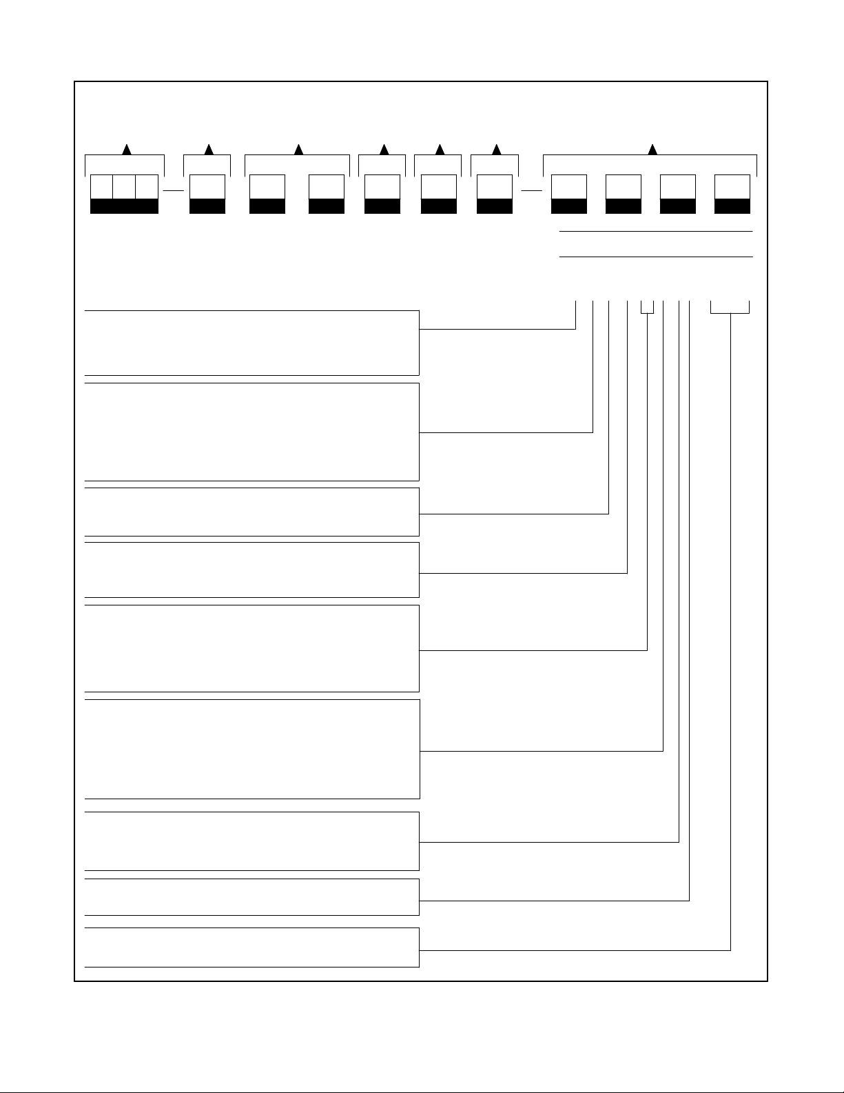
Interpreting a Transfer Switch Part Number
Record the transfer switch part number in the boxes below. The transfer switch part number defines
characteristics and ratings as explained in the accompanying chart.
Type of Switch Type of Logic Voltage & Frequency
Number of
Poles
Number of
Wires
Type of
Enclosure Amperage Rating Code
Kohler Part Number Key
This chart explains the Kohler transfer switch part numbering code system. The
sample part number shown is for a standard molded-case switch with M340+ logic
rated at 480 volts, 60 hertz, 3-phase, 3-pole, and 4 wires in a NEMA 1 enclosure with
an amperage rating of 80 amperes.
Classification of Power Switch
M: Switch or Circuit Breaker
T: Electrically & Mechanically Held
Z: Contactor Style
Type of Power Switch
C: Contactor
E: Electrically Held Contactor
L: Mechanically Held Contactor
M: Molded-Case Circuit Breaker
N: Molded-Case Switch (no protection)
Type of Switch
S: Standard
B: Bypass
Type of Logic
5: M340+
6: M340+ with programmed transition
Voltage Code
60:600 Volt, 60 Hz 66: 480 Volt, 60 Hz
62:120 Volt, 60 Hz 68: 208 Volt, 60 Hz
63:220 Volt, 50 Hz 71: 380 Volt, 50/60 Hz
64:240 Volt, 60 Hz
SAMPLE PART NUMBER
MNS-566341-0080
Number of Poles
2: 2 pole, 1 phase (MM_, MN_, TE_, TL_, devices
will be supplied with 3 poles)
3: 3 pole, 3 phase
6: 4 pole, fully rated switched poles
(no overlapping neutral)
Number of Wires
2: 2 wire
3: 3 wire
4: 4 wire
Enclosure
1: NEMA type 1
Amperes
Available sizes vary with the type of switch.
Figure 1-4. Transfer Switch Model Description
TP-5672 11/95
Specifications 1-3
Page 15

Specifications
The specifications listed below are for the M340+ logic
controller. See the respective power switching device
manual for its specifications.
Standard Features
D Normal source voltage sensing adjustable from
75% to 130% of normal for pickup and from 70% to
135% for dropout; provides monitoring line-to-line
for all phases of 3-phase switches.
D TDNE (Time Delay Normal-to-Emergency)
adjustable 0 to 5 minutes.
D TDES (Time Delay Engine Start) adjustable from
0 to 6 seconds.
D TDEN (Time Delay Emergency-to-Normal)
adjustable 0 to 30 minutes.
D Program Transition (Center off)—time delay
during transfer with neither source connected to
the load. Adjustable 0 to 2 minutes.
D LCD digital voltmeter.
D LCD digital running time meter.
D LCD digital transfer counter.
D LCD digital frequency meter.
D Status panel with keypad data entry.
D Area protection with override.
D TDEC (Time Delay Engine Cooldown) adjustable
from 0 to 30 minutes.
D Generator engine start contacts.
D Indicators for switch position—normal and
emergency.
D Indicators for source available—normal and
emergency.
D Lamp test switch, momentary.
D Underfrequency sensing—one phase emergency
source only.
1-4 Specifications TP-5672 11/95
Page 16

Shunt-Jumper-Controlled Accessories
Enable or disable shunt-jumper-controlled accessories
by altering socket JP1 on the main logic board. See
Figure 1-5. All shunt-jumper features are disabled from
thefactoryunlessthe function was ordered atthetimeof
purchase. But features can be enabled after factory
delivery by adding jumpers to the JP1 socket.
Main Logic Board
JP1
MANUAL
TIME
PLANT
VOLT/
PHASE
OFF
Figure 1-5. Logic Board Accessory Programming
Shunts
D Manual Override. Enabling manual override
allows automatic transfer to an available source
when the connected source fails. Transfer time
delays will be bypassed. Disabling manual
override causes the logic board to wait for manual
operation. The logic board will not automatically
seek the available source.
D Inphase Monitor. Abnormal inrush currents from
switching between two live power sources can
damage motors and related equipment. The
purpose of the inphase monitor is to minimize
abnormal inrush currents to equipment when the
ATS transfers from one source to a new power
source. The inphase monitor samples a single
phase of one source and compares it to a single
phase of the other source. When the two voltages
are within the desired phase angle and
approaching a zero phase angle difference, the
inphase monitor signals the transfer switch to
OVRIDE
DELAY
EXER
FREQ
SEQUENCER
MONITORIN-PHASE
DELAYS
567215
operate. The transfer may be from utility to
generator,from generator to generator,or utility to
utility.
NOTE
This option is available only on contactor type,
nonprogrammed transition switches. If the
contactor is not of this type, then the controller will
not allow this option to be enabled. Enable this
accessory by installing the INPHASE MONITOR
jumper on the controller’s main logic board.
D Phase Rotation and Anti-Single Phasing. This
function provides source monitoring for both the
normal and emergency sources. The feature
includesphaserotation(A B C only)andanti-single
phase protection. This option must be used in
conjunction with accessory DD-05-K in order to
provide source monitoring on the emergency side.
Enable this accessory by installing the PHASE
SEQUENCER jumper on the controller’s main
logic board.
D Normal and Emergency Source Sensing. This
function provides overvoltage sensing on all
phasesof the normalsource,over/underfrequency
sensing on one phase of the normal source,
overvoltage sensing on one phase of the
emergency source, and overfrequency sensing on
one phase of the emergency source. Enable this
accessory by installing theVOLT/FREQjumper on
the controller’s main logic board.
D Plant Exerciser. This function enables a no-load
plantexerciser.Userhasachoice of 7-day,14-day,
or calendar-based exercise modes. Enable this
accessory by installing the PLANT EXER jumper
on the controller’s main logic board.
D Extended Time Delay. This function extends the
time delay to 99 minutes for TDNE, TDES, TDEN,
TDOE, TDON, and TDEC. Enable this accessory
by installing the TIME DELAY jumper on the
controller’s main logic board.
D Off Position Time Delay. This function enables
the time delay during transfer when neither source
is connected to the load. Enable this accessory by
installing the OFF DELAYS jumper on the
controller’s main logic board.
Optional Accessories
See Appendix C for details of optional accessories. The
nameplate includes a list of the accessories selected.
See Figure 1-3.
TP-5672 11/95
Specifications 1-5
Page 17
Section 2. Operation
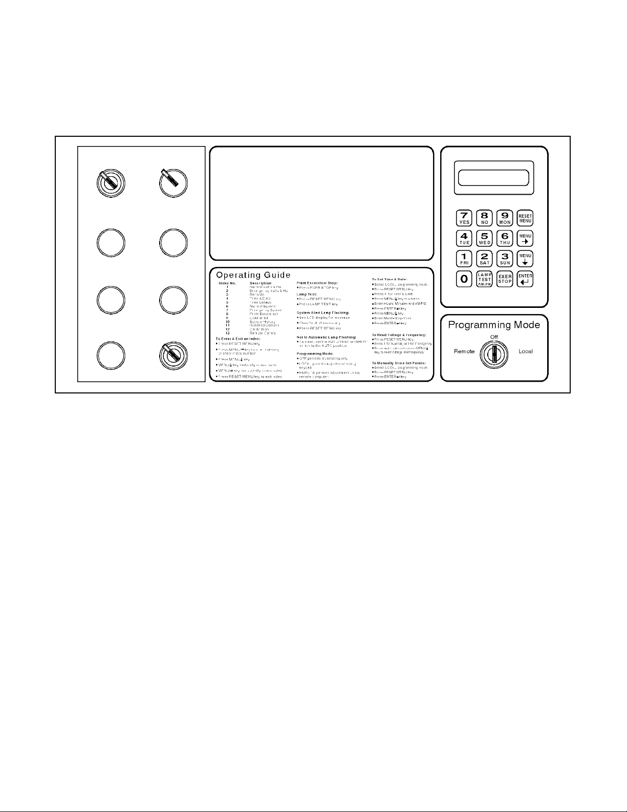
Control Switches and Indicators
Various optional control switches and indicator lamps
may be present on the transfer switch door depending
AUTO
TRANSFER
MANUAL
TRANSFER TO
EMERGENCY
MANUAL
TRANSFER TO
OFF
MANUAL
TRANSFER TO
NORMAL
MANUAL
TRANSFER
TEST SWITCH
NORMAL TEST
BYPASS
EMERGENCY TO
NORMAL TIME DELAY
BYPASS NORMAL
TO EMERGENCY
TIME DELAY
AUTO INHIBIT
Contactor Position Time Delays
Normal On EndEmergency
·
Source Available
Normal Emergency
· ·
System Status
Not In Automatic
· ·
Programming Mode Not in Off
·
Flashing, Local Steady,Remote
· ·
Plant Exerciser Load Shed Inphase Monitor Area Protection
· · · ·
Off
·
·
System Alert
Accessory Active
on the options chosen. See Figure 2-1 for LED, Switch,
and Key locations.
Engine Start
·
·
Normal To Emergency
·
·
Emergency To Normal
·
·
Engine Cooldown
·
·
Off Position
·
·
Figure 2-1. Front Panel
LED Indicators
Contactor Position. LEDs indicate transfer switch
position—NORMAL (green), EMERGENCY (red), or
OFF (yellow).
Source Available. LEDs indicate source with
acceptable voltage and frequency—Normal (green)
and/or Emergency (red).
System Status
Not in Automatic (red). LED flashes to indicate that
Test switch is actuated, or Auto/Manual switch is in the
Manual position.
System Alert (red). LED flashes to indicate possible
problem with contactor or logic operation. System alert
will also flash if any fault signals are received from the
generator set.
Programming Mode Not in Off (yellow). LED flashes
to indicate that programming switch is in the LOCAL
position. A steady, nonflashing light indicates that the
programming switch is in the REMOTE position.
Operation 2-1TP-5672 11/95
Page 18

Time Delays
Engine Start (If emergency source is a generator set).
ON LED indicates that engine-start time delay is timing.
ENDLED indicates thattheengine has been signaledto
start.
Normal to Emergency. ON LED indicates that the
normal-to-emergency time delay is timing. END LED
indicates that the time delay has completed timing.
Emergency to Normal. ON LED indicates that the
emergency to normal time delay is timing. END LED
indicates that the time delay has completed timing.
transfer from emergency to normal and normal to
emergency when sources are near synchronization.
NOTE
When a programmed transition switch is ordered, the
inphase monitor option is disabled by the
microprocessor.
Area Protection. Area protection LED indicates that
the controller is in the area protection mode. The
generator will be signaled to START and the contactor
will transfer to the emergency positionand remain there
while in area protection.
Engine Cooldown. ON LED indicates that the
generator set engine cooldown timer is timing. END
LED illuminates until the engine has shut down.
Off Position. ON LED indicates that the time delay off
positionistiming. ENDLEDindicatesthatthetimedelay
has completed timing.
Accessory Active
Plant Exerciser. Plant excerciser LED indicates that
the system is in the exerciser mode.
LoadShed. LoadshedLEDindicates that programmed
load shedding is active.
Inphase Monitor (availableon ZCtype powerswitches
only). Inphase monitor LED indicates that the sources
are being monitored for phase relationship to allow
inphase transfer. The inphase monitor will permit
Control Switches
Test Switch (Standard). Move the test switch to the
TEST position to simulate a normal source outage.
Not-in-Automatic system status light will flash.
Bypass N-E Time Delay Pushbutton Switch
(Option). If the bypass normal-to-emergency time
delay pushbutton is pressed when
normal-to-emergency time delay is on, time delay will
end.
Bypass E-N Time Delay Pushbutton Switch
(Option). If the bypass normal-to-emergency time
delay pushbutton is pressed, when
emergency-to-normal time delay is on, time delay will
end.
Manual Transfer to Emergency Switch (Option).
When the transfer switch control is in the manual mode
of operation and manual to emergency is required,
press the manual transfer-to-emergency pushbutton to
Programming Mode Switch
NOTE
Theprogramming modeswitch keysshould bekept ina
safe place to prevent unwanted tampering with the
transfer switch control. Do not leave the programming
switch in the LOCAL position with the transfer switch
unattended.
Remote. Allows both status monitoring and setting of
the transfer switch controls by a connected personal
computer.
Off. Transfer switch status settings and power source
may be monitored from the local LCD display or
connected computers.
Local. Allows both status monitoring and setting of
transfer switch control from the microprocessor’s LCD
display and keypad.
cause the transfer switch to transfer to the emergency
position.
Manual Transfer to Off Switch (Option). When the
transfer switch control is in the manual mode of
operation and manual to off is required, press the
manual transfer-to-emergency pushbutton to cause the
transfer switch to transfer to the off position.
Manual Transfer to Normal Switch (Option). When
the transfer switch control is in the manual mode of
operation and manual to normal is required, press the
manual transfer-to-emergency pushbutton to cause the
transfer switch to transfer to the normal position.
Auto/Inhibit Switch (Option). If the auto/inhibit switch
is in the AUTO position, the transfer switch will operate
normally. If the switch is in the Inhibit position, the
transfer switch will not transfer under any conditions.
2-2 Operation TP-5672 11/95
Page 19

Sequence of Operation
This section describes the correct operation of a
microprocessor-controlled transfer switch.
Sequence of Operation Standard Switch
When the Normal Source Fails
1. The source-available normal LED turns off.
2. The time-delay-engine-start ON LED illuminates
to indicate the engine-start-time-delay is timing.
3. The time-delay-engine-start END LED illuminates
to indicate the engine has been signaled to start.
4. The source-available emergency LED
illuminates.
5. The time-delay normal-to-emergency ON LED
illuminates to indicate the normal-to-emergency
time delay is timing.
6. The time-delay normal-to-emergency END LED
illuminates to indicate the time delay has
completed timing.
7. The load-shed LED illuminates at the same time
all loads to be shed are disconnected from the
switch (if equipped with load-shed option).
8. The inphase monitor LED illuminates (if equipped
with inphase monitor option on ZC type power
switches only). The controller monitors the two
voltagesto makesure theyare ata desiredphase
angle and approaching zero phase angle
difference.
9. The contactortransfers tothe emergency position
after the load-shed time-before-transfer timer has
completed timing. The contactor-position normal
LED turns off and the contactor-position
emergency LED illuminates. The inphase monitor
LED turns off.
10. After the load-shed time-after-transfer timer has
completed timing, the selected loads for the
emergencysource are nowreturnedto the switch.
The load-shed LED turns off (if equipped with
load-shed option).
Operation 2-3TP-5672 11/95
Page 20

When the Normal Source Returns
1. The source-available, normal LED illuminates.
completed timing. The contactor-position
emergency LED turns off and the
contactor-position normal LED illuminates.
2. The time-delay emergency-to-normal ON LED
illuminates to indicate the emergency-to-normal
time delay is timing.
3. The time-delay emergency-to-normal END LED
illuminates to indicate the time delay has
completed timing.
4. The load-shed LED illuminates at the same time
all loads to be shed are disconnected from the
switch (if equipped with load-shed option).
5. The inphase monitor LED illuminates (if equipped
with load-shed option).
6. The contactor transfers to the normal position
after the load-shed time-before-transfer timer has
7. After the load-shed time-after-transfer timer has
completed timing, the selected loads for the
normal source are returned to the switch. The
load-shed LED turns off (if equipped with
load-shed options).
8. The time-delay engine-cooldown ON LED
illuminates to indicate the generator set engine
cooldown timer is timing.
9. The time-delay engine-cooldown END LED stays
illuminated until the generator has shut down.
10. The source-available, emergency LED turns off.
2-4 Operation TP-5672 11/95
Page 21
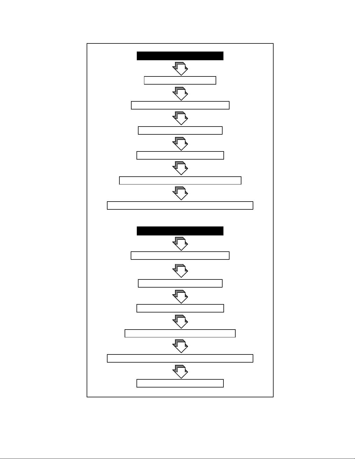
Microprocessor-Controlled Transfer Logic
Standard Switch
Normal Source Failure
Time Delay Engine Start
Time Delay Normal-to-Emergency
Load Shed (all)—if equipped
Inphase Monitor—if equipped
Contactor Transfer to Emergency Position
Load Return (programmed sequence)—if equipped
Normal Source Return
Time Delay Emergency-to-Normal
Load Shed (all)—if equipped
Inphase Monitor—if equipped
Contactor Transfer to Normal Position
Load Return (programmed sequence)—if equipped
Time Delay Engine Cooldown
Operation 2-5TP-5672 11/95
Page 22

Sequence of Operation Programmed Transition Switch
When the Normal Source Fails
NOTE
When a programmed transition switch is ordered, the
inphase monitor option is disabled by the
microprocessor.
1. The source-available, normal LED turns off.
2. The time-delay-engine-start ON LED illuminates
to indicate the engine-start-time-delay is timing.
3. The time-delay-engine-start END LED illuminates
to indicate the engine has been signaled to start.
4. The source-available emergency LED illuminates
after the generator is at rated voltage and
frequency.
5. The time-delay normal-to-emergency ON LED
illuminates to indicate the normal-to-emergency
time delay is timing.
6. The time-delay normal-to-emergency END LED
illuminates to indicate the time delay has
completed timing.
7. The load-shed LED illuminates at the same time
all loads to be shed are disconnected from the
switch (if equipped with load-shed option).
8. After the load-shed time-before-transfer timerhas
completed timing, the contactor transfers to the
Off position. The contactor-position normal LED
turns off and the contactor-position Off LED
illuminates.
9. The time-delay-off-position ON LED illuminates to
indicate the Off position time delay is timing.
10. The time-delay-off-position END LED illuminates
to indicate the time delay has completed timing.
11. The contactor transfers to the emergency
position. The contactor-position Off LED turns off
and the contactor-position emergency LED
illuminates.
12. After the load-shed time-after-transfer timer
completes timing, the selected loads for the
emergencysource arereturned to the switch. The
load-shed LED turns off (if equipped with
load-shed option).
2-6 Operation TP-5672 11/95
Page 23

When the Normal Source Returns
1. The source-available, normal LED illuminates.
2. The time-delay emergency-to-normal ON LED
illuminates to indicate the emergency-to-normal
time delay is timing.
3. The time-delay emergency-to-normal END LED
illuminates to indicate the time delay has
completed timing.
4. The load-shed LED illuminates at the same time
all loads to be shed are disconnected from the
switch (if equipped with load-shed option).
5. After the load-shed time-before-transfer timerhas
completed timing, the contactor transfers to the
Off position. The contactor-position emergency
LED turns off and the contactor-position Off LED
illuminates.
6. The time-delay off-position ON LED illuminates to
indicate the off-position-time-delay is timing.
7. The time-delay off-position END LED illuminates
to indicate the time delay has completed timing.
8. The contactor transfers to the normal position.
The contactor-position OFF LED turns off and the
contactor-position normal LED illuminates.
9. After the load-shed time-after-transfer timer has
completed timing, the selected loads for the
normal source are returned to the switch. The
load-shed LED turns off (if equipped with
load-shed option).
10. The time-delay-engine-cooldown ON LED
illuminates to indicate the generator set engine
cooldown timer is timing.
11. The time-delay-engine-cooldown END LED stays
illuminated until the generator has shut down.
12. The source-available emergency LED turns off.
Operation 2-7TP-5672 11/95
Page 24
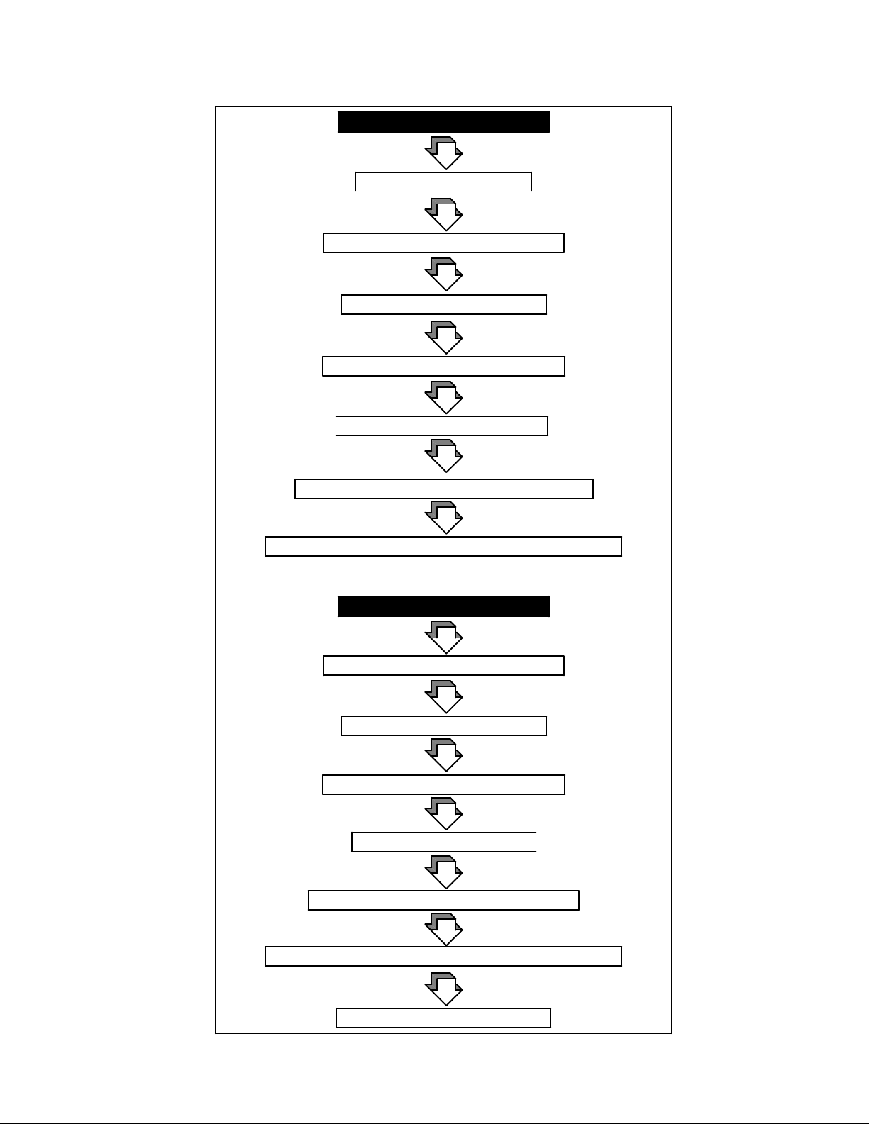
Microprocessor-Controlled Transfer Logic
Programmed Transition Switch
Normal Source Failure
Time Delay Engine Start
Time Delay Normal-to-Emergency
Load Shed (all)—if equipped
Contactor Transfer to Off Position
Time Delay Off-to-Emergency
Contactor Transfer to Emergency Position
Load Return (programmed sequence)—if equipped
Normal Source Return
Time Delay Emergency-to-Normal
Load Shed (all)—if equipped
Contactor Transfer to Off Position
Time Delay Off-to-Normal
Contactor Transfer to Normal Position
Load Return (programmed sequence)—if equipped
Time-Delay-Engine-Cooldown
2-8 Operation TP-5672 11/95
Page 25

To Disconnect The P1 Plug
1. If the transfer switch isin the normal position, open
the emergency-source circuit breaker.
it is available, after a time delay. For immediate
retransfer, open and then reclose the
emergency-source circuit breaker. Place the
generator set start switch in the AUTO position.
2. If the transfer switch is in the emergency position,
open the normal-source circuit breaker.
3. Separate the in-line disconnect plug by grasping
and squeezing the plug. Do NOT pull on the wires.
560423
Electrical Operation Test
Place the transfer switch in the NORMAL position. Use
thefollowing procedureto check theelectrical operation
of the automatic transfer switch:
1. Press andhold the testpushbutton for 15seconds.
See Figure 2-1.
2. The generator set should start and run after the
time delay engine start (TDES) completed timing.
3. The transfer switch will transfer to the emergency
position. The transfer occurs after the
normal-to-emergency time delay (TDNE) has
completed timing.
4. Release the test pushbutton. The transfer switch
retransfers to normal after the
emergency-to-normal time delay.
5. Time delay engine cooldown (TDEC) allows the
engineto continue running foranunloaded running
time. The transfer switch TDEC will complete
timing before any TDEC function in the generator
set controller begins timing.
6. Close load circuit breaker(s) when loads may be
safely energized.
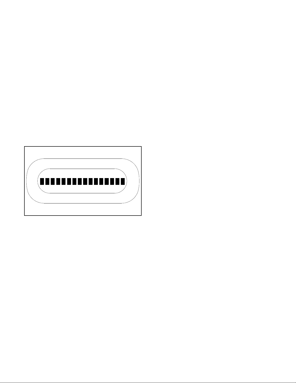
Figure 2-2. In-Line Disconnect Plug
To Reconnect The P1 Plug
1 Engage the in-line disconnect plugby grasping the
connectors and pressing them together. See
Figure 2-2.
2 If thetransfer switch isin the normalposition, place
thegenerator set startswitchin the AUTOposition.
Then close the emergency-source circuit breaker.
3. If the transfer switch is in the emergency position,
close the normal-source circuit breaker. The load
willautomatically retransferto the normalsource, if
NOTE
Connecting the transfer switch in-line disconnect
plugs(P1)togetherwhen the generator controller’s
master switch is in the AUTO position causes the
generator set to IMMEDIATELY start and run until
the generator set controller’s cooldown timer
completes timing.
This completes functional tests of the transfer switch.
Leave the AUTO/MANUAL switch in the AUTO
TRANSFER position.
Operation 2-9TP-5672 11/95
Page 26

Section 3. Troubleshooting Guide
For location of pushbuttons, switches, LEDs, and keys
referred to in this section, see Figure 2-1. Refer to
Figure 3-1 as a guide to troubleshooting problems with
Problem Refer to Section 4—Controller Troubleshooting
None of the LEDs are on and the LCD is blank Power to the system
Pressing a key on the keypad does not supply the appropriate
response
Every LED does not turn on and every character block on the LCD
does not blacken
The normal source should be available but the Source-Available,
Normal LED is not on
The emergency source should be available but the
Source-Available, Emergency LED is not on
The Automatic/Test pushbutton is pressed, the Automatic/Inhibit
switch (option DD-09) is set to Inhibit, or the Automatic-Transfer key
switch (option DD-29) is set to manual, but the System-Status,
Not-In-Automatic LED is not flashing
The System-Status, System-Alert LED is flashing; check the LCD
for a message
The LCD displays Auxiliary-Switch Fault or Double Auxiliary--Switch
fault message
The LCD displays Transfer Hang error message Transfer hang error message
The LCD displays Power-Down error message Power-down error message
The LCD displays RAM or Memory error message RAM or memory error message
The Programming-Mode-Not-In-Off LED is flashing Programming-mode-not-in-off
The engine operates when it should not be operating Engine operates when it should not
The engine should start Engine will not start
One of the control options is not working (the control options
include the inphase monitor, source-phase-sequence,
normal/emergency voltage/frequency sensing, plant exerciser,
extended time delay,and manual override)
the microprocessor logic controller. Refer to Figure 3-2
as guide to troubleshooting problems with the
microprocessor accessories.
Keypad and status panel
Keypad and status panel
Source-available, normal error
Source-available, emergency error
System-status, not-in-automatic error
System-status, system-Alert error
Auxiliary-switch fault or double auxiliary-switch fault error
message
Shunt-jumpered controlled options
TP-5672 11/95
Figure 3-1. Microprocessor logic controller troubleshooting chart
TroubleshootingGuide
3-1
Page 27

Problem Refer to Section 5—Accessory Troubleshooting
Controller will not sense three-phase emergency voltage Phase sequencer,accessory DD-05
The generator set does not start when the test switch is in the
Test switch, accessory DD-06 and DD-07
engine start position
The generator set does not start when the test switch is in the test
Test switch, accessory DD-06 and DD-07
position
The normal-to-emergency time delay pushbutton does not work Time delay override, accessory DD-08
The emergency-to-normal time delay pushbutton does not work Time delay override, accessory DD-08
The auxiliary dry contacts relay boards do not operate Relay auxiliary dry contacts, accessory DD-14
The analog meters are not working Meters, accessory DD-18
The battery charger is not working Battery charger, accessory DD-24
The manual transfer to emergency source does not work Manual operation switches, accessory DD-29
The manual transfer to normal source does not work Manual operation switches, accessory DD-29
The manual transfer to off does not work Manual operation switches, accessory DD-29
The auto/manual switch does not work in the manual position Manual operation switches, accessory DD-29
The auto/manual switch does not work in the auto position Manual operation switches, accessory DD-29
The load shed contacts do not work Load-shed contacts, accessory DD-35
Problems with remote communication exist Remote communication—RS/232 or RS/485, accessory
DD-51
Figure 3-2. Accessory troubleshooting chart
3-2 TroubleshootingGuide
TP-5672 11/95
Page 28
Section 4. Controller Troubleshooting
The following section will assist in solving common
problems with the M340+ controller. Note any optional
accessoriesthatmayhavebeenfurnishedonthisswitch
Is the LCD screen blank
and no LEDs illuminated?
Is there 19 vac between terminals
TB-AC1-NAS and TB-AC1-NCS of
the power supply board?
No
Yes
Replace the power
supply board.
Is a battery connected to terminals
TB-DC1-29 and TB-DC1-34 of the
power supply board?
Yes
Is there rated battery voltage
between terminals TB-DC1-29
and TB-DC1-34 of the power
supply board?
No
Check battery and wiring
from battery to assembly
for open of shorted leads.
Is an optional remote
communications board
installed?
Yes No
Is there 10 vdc between pin P2-13
of plug 2 and terminals TB-DC1-34
of the power supply board?
Is there normal source
voltage between terminals
TB-AC1-NA and TB-AC1-NC
of the power supply board?
Is there 10 vdc between terminals
TB-DC1-30 and TB-DC1-34 of
the power supply board?
No
Replace the
load-shed board.
No
and review their operation in section 5—Accessory
Troubleshooting.
No
Yes
Is there from 12 to 30 vdc
No
Yes
Yes Yes
Yes
between terminals
TB-DC1-23 and TD-DC1-34
of the power supply board?
Replace the
logic board.
Yes
Troubleshooting
complete.
Check the normal source
and contactor-to-power
supply board wiring harness
for open or shorted leads.
Yes
Is there an optional
load-shed board
installed?
No
Disconnect the
load-shed board.
Yes
Recheck the voltage at terminals
TB-DC1-23 and TB-DC1-30 of the
power supply board, and pin P2-13
of plug 2. Are the voltages correct?
No
No
Yes
Disconnect the
communications
board.
Recheck the voltage at terminals TB-DC1-23
and TB-DC1-30 of the power supply board, and
pin P2-13 of plug 2. Are the voltages correct?
No
Replace the logic board.
TP-5672 11/95
No
Recheck the voltage at terminals TB-DC1-23
and TB-DC1-30 of the power supply board, and
pin P2-13 of plug 2. Are the voltages correct?
Yes
Yes
Replace the remote
communication board.
Yes
Replace the power supply board.
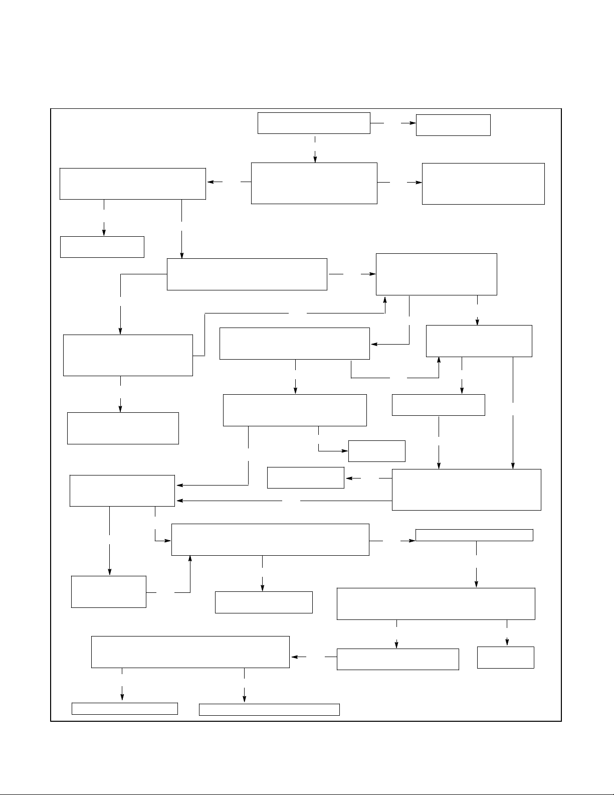
Figure 4-1. Troubleshooting—Power to the system
Yes
No
Recheck the voltage at terminals TB-DC1-23
and TB-DC1-30 of the power supply board, and
pin P2-13 of plug 2. Are the voltages correct?
Disconnect the status panel
board.
Disconnect the logic board.
No
Controller Troubleshooting
No
Yes
Replace the
logic board.
4-1
Page 29

Power to the System
Ifthereisaproblemwiththelogicboard,thefirststepisto
check the status panel. If no LEDs on the status panel
are illuminated and the liquid crystal display (LCD) is
blank, check the power to the system by performingthe
following steps. See Figure 4-1 for the Power to the
System troubleshooting flowchart. See Appendix B
Figure B-4 for location of power supply board
components referred to in this section. See Appendix B
FigureB-6forlocationanddescriptionofP2ribboncable
pins. See Appendix B Figure B-9 for location of main
logic board components referred to in this section.
1. Using a voltmeter, connect one test lead to
TB-AC1-NA. Connect the other test lead to
TB-AC1-NC. If the voltmeter does not read the
expected normal source voltage,check the normal
sourceandthecontactor-to-assemblyharness,P1.
2. If thenormalsourcevoltageispresent,connectone
test leadto TB-AC1-NAS and the other test leadto
TB-AC1-NCS. If the voltmeter does not read
approximately 19 volts AC, the secondary normal
source voltage, check that the transformer is wired
correctly. If the transformer is wired correctly and
the voltmeter still does not read 19 volts AC,
disconnect transformer secondary wires andretest
transformer secondary voltage to determine if the
transformer or the logic board assembly is at fault.
3. If boththenormalsourcevoltageandthesecondary
normal source voltage are present, connect one
test lead to TB-AC1-EA and the other test lead to
TB-AC1-EC. If the voltmeter does not read the
expected emergency source voltage, check the
emergency source and the contactor-to-assembly
harness, P1.
4. If theemergencysourcevoltageispresent,connect
one test lead to TB-AC1-EAS and the other test
leadtoTB-AC1-ECS.If thevoltmeterdoesnot read
approximately19voltsAC,theexpectedsecondary
emergency source voltage, check that the
transformer is wired correctly. If the transformer is
wiredcorrectly andthe voltmeter still doesnot read
19 volts AC, disconnect transformer secondary
wires and retest transformer secondary voltage to
determine if the transformer or the logic board
assembly is at fault.
5. If the emergency source, normal source, and
transformers are all working properly, and the
batteryback-upoptionisused,connectthe positive
testleadtoTB-DC1-29andthe negativetestleadto
TB-DC1-34.If thevoltmeterdoesnot read between
12and30voltsDC,expectedbatteryvoltage,check
the battery-to-assembly wires and the battery.
6. Connect the positive test lead to TB-DC1-23, and
the negative test lead to TB-DC1-34. If the
voltmeter does not read betweenapproximately12
and30voltsDC,checkifanaccessoryisconnected
toTB-DC1-23.Ifthereisanaccessoryconnectedto
TB-DC1-23,disconnectit. If the voltmeter stilldoes
notread between12and30 voltsDC, performstep
9.
NOTE
When taking a voltage or resistance measurement
at a ribbon cable pin, do not disconnect the ribbon
cable from the board. Use a needle point probe to
take the readings from the holes on the top side of
the ribbon cable connector.
7. Connect the positive test lead to P2-13, and the
negative test lead to TB-DC1-34. If the voltmeter
does not read approximately 10 volts DC, perform
step 9. See Appendix B Figure 6 for location of P2
ribbon cable pins.
8. Connect the positive test lead to TB-DC1-30 and
the negative test lead to TB-DC1-34. If the
voltmeterdoesnotreadapproximately10voltsDC,
perform step 9.
9. If eachofthemeasurementstakeninsteps6,7,and
8 was correct, this step may be skipped.
a. Disconnect the main logic board ribbon cable
from P2, and recheck the voltages in steps 6, 7,
and8. If thevoltagereadings in steps 6,7, and8
are now correct, the main logic board is
defective. Replace the logic board assembly.
b. If the logic board is equipped with a load shed
board, disconnect the load shed ribbon cable
from P10 on the main logic board, and recheck
the voltages in steps 6, 7, and 8. If the voltage
readings in steps 6, 7, and 8 are now correct,
replace the Load Shed board.
c. If the logic board is equipped with a remote
communications board, disconnect the remote
communications ribbon cable from P12 on the
main logic board, and recheck the voltages in
steps6, 7, and 8. If thevoltagereadings in steps
6, 7, and 8 are now correct, replace the remote
communications board.
d. Disconnect the status panel ribbon cable from
P4,andrecheckthevoltagesinsteps6,7, and8.
If the voltage readings in steps 6, 7, and 8 are
now correct, the status panel is defective.
Replace the logic board assembly.
e. If the voltages measured in steps 6, 7, and 8
were never correct, replace the power supply
board.
4-2 Controller Troubleshooting
TP-5672 11/95
Page 30
Keypad And Status Panel
For location of pushbuttons, switches, LEDs, and keys
referred to in this section, see Figure 2-1.
1. Testthe keypadby pressinga keyandcheckingthe
response.If theresponseiscorrect,repeatthisstep
until satisfied that there is not a problem with the
keypad. If the response is ever incorrect, the
keypad is defective. Replace the logic board
assembly.
2. Press the LAMP TEST key on the keypad.
3. If afterpressingtheLAMPTEST keysomeLEDson
thedisplaypanelareon, butat leastoneLED isnot
on, the status panel is defective. Replace the logic
board assembly.
4. If after pressing the LAMP TEST key some of the
character blocks on the LCD appear black, but at
least one character block is not black, the status
panel is defective. Replace the logic board
assembly.
5. If after pressing the LAMP TEST key no LEDs are
on, and the character blocks in the LCD are black,
verify that there is power to the system by
performing the steps outlinedin Section 4—Power
To The System. Check the P2 and P4 ribboncable
connections by performingthefollowingsteps. See
Appendix B FigureB-9 for locationof ribboncables
andotherpowersupplyboardcomponentsreferred
to in this section.
a. Disconnect all power sources.
b. Wait 30 seconds.
c. Being careful not to bend or break any of the
pins, remove both P2 and P4 ribbon cable
connectors.
d. Inspect the pins on the P2 and P4 ribbon cable
connectors.
e. If pinsarebent,carefullybendthemback. Ifpins
are broken, replace the ribbon cable connector.
f. Carefully reconnect P2 and P4 ribbon cable
connector.
g. If the problem still exists,replacethe logic board
assembly.
560442
Figure 4-2. The M340+ LCD display during a lamp
test
TP-5672 11/95
Controller Troubleshooting
4-3
Page 31

If the normal source is available, but the source available normal LED
is not illuminated. Check the trip point settings in index 6. See TP-5664
for programming information. Are the trip points programmed correctly?
Yes
Does the microprocessor display,in index 1, rated normal source voltages and frequency?
No
Correct the trip point settings
in index 6. See TP-5664 for
programming information.
Is the transfer switch
wire with a phase
Yes
rotation of ABC?
Yes
No
Replace the
logic board.
Calibrate the normal source
voltage.
Yes
Does the voltage between terminals TB-AC1-NA
and TB-AC1-NB and terminals TB-AC1-NB and
TB-AC1-NC of the power supply board equal the
rated voltage for the transfer switch?
No
Check the normal source voltage
and the wiring harness from the
contactor to power supply board
for open or shorted leads.
Yes
Is the inphase
sequence option
installed?
Yes
Does the voltage between terminals
TB-AC1-NC and TB-AC1-NA of the
power supply board equal the rated
voltage for the transfer switch?
No
Is 3-phase
sensing used?
No
Check the normal source voltage
and the wiring harness from the
contactor to power supply board
for open or shorted leads.
Is the voltage between pin P2-15 of
Yes
plug 2 and terminal TB-DC1-34 of the
power supply board 1/25 of line
voltage? See Appendix B Figure B-5.
Yes
Turn the generator set off. Jumper terminal
TB-DC1-24 to TB-DC1-34 of the power
supply board . Is the voltage between pin
P2-15 of plug 2 and terminal TB-DC1-34 of
the power supply board equal to 0 vac?
No
No
Replace the power
supply board.
No
Replace the power
supply board.
No
Yes
Is 3-phase
sensing used?
Yes
No
Calibrate the controller’s
normal source voltage.
Is the voltage between pin P2-18 of
plug 2 and terminal TB-DC1-34 of the
power supply board 1/25 of line
voltage? See Appendix B Figure B-5.
Yes
Replace the power
supply board.
Rewire the source for
ABC phase rotation.
Figure 4-3. Troubleshooting—Source-available, normal error
Yes
Is the voltage between pin P2-16 of plug 2 and
terminal TB-DC1-34 of the power supply board
1/25 of line voltage? See Appendix B Figure
B-5.
No
Is the voltage between pin P2-17 of
plug 2 and terminals TB-DC1-34 of
the power supply board 1/25 of line
voltage? See Appendix B Figure B-5.
No
No
Replace the power
supply board.
No
Replace the power
supply board.
Yes
Calibrate the controller’s
normal source voltage.
4-4 Controller Troubleshooting
TP-5672 11/95
Page 32

For location of pushbuttons, switches, LEDs, and keys
referred to in this section, see Figure 2-1.
This section covers the condition in which the normal
source is available but the Source-Available, Normal
LED is not on.
The first item to check is the trip-point settings. The
trip-pointsettingscan be foundinIndex 6 inthe program
menu. See Figure 4-4 for recommended trip-point
settings.Thetrip-pointsdonotneedtoexactlymatchthe
recommended trip-point settings for proper operation.
However, if the trip-point settings in Index 6 are too high
ortoo low,problemscouldoccur. Ifthe trip-pointsettings
are too high or too low, correct them. Then enter normal
source voltage and normal source frequency, and store
the set points.
Next check Index 1 in the program menu for correct
normal source voltage and frequency reading. If the
voltage and frequency values in Index 1 match the
voltage and frequency values in Index 6, perform the
following steps.
1. Check if the phase sequence option is installed. If
thereisa jumperacrossJP1-5,thephasesequence
option is installed.
2. If the phase sequence option is installed, press the
MENU arrow down key to check the phase
sequence in Index 1. Utility power must be
phased ABC.
3. If the normal source is single-phase,verify inMenu
Index 6 that single-phase sensing was selected. A
single-phase source must be sensed as a
single-phase source.
Trip Point Setting Limits
Overvoltage
Dropout
Overvoltage
Pickup
Undervoltage
Pickup
Undervoltage
Dropout
Overfrequency
Dropout
Overfrequency
Pickup
Underfrequency
Pickup
Underfrequency
Dropout
105% -- 135% 115%
100% -- 130% 110%
75% -- 100% 90%
70% -- 95% 85%
105% -- 135% 115%
100% -- 130% 110%
85% -- 100% 90%
80% -- 95% 85%
Normal Source
Factory Setting
Figure 4-4. Normal source voltage trip point
setting limits and factory settings
4. If the source is available, the phase sequencing is
correct, the sensing is correct, and the
Source-Available, NormalLED is still not on, check
the P2 ribbon cable connector.
a. Remove all power sources.
b. Wait for 30 seconds.
c. Makingsurenot to bendor breakanyofthepins,
remove the P2 ribbon cable connector.
d. Inspect the pins on the P2 ribbon cable
connector.
e. If any of the pins are bent, carefully bend them
back. If any of the pins are broken, the ribbon
cableconnectorisdefective.Replacetheribbon
cable connector.
f. Carefully, reconnect P2 ribboncable connector.
5. If the Source-Available, Normal LED is still not
illuminated, the status panel is defective. Replace
the logic board assembly. If a value in Index 1 is
incorrect, see steps below.
TP-5672 11/95
Controller Troubleshooting
4-5
Page 33

Incorrect Normal Source Voltage And Frequency Values
See Appendix B, Figure B-9 for location of TB-AC1 and
other power supply boardcomponents referredto inthis
section.
1. If the system is single-phase, use a voltmeter to
measure the normal source voltage by connecting
onetest leadto TB-AC1-NA and theother test lead
to TB-AC1-NC. Note the voltmeter reading.
2. If the system is three-phase, use a voltmeter to
measure the normal source voltage by connecting
onetest leadto TB-AC1-NA and theother test lead
to TB-AC1-NB. Note the voltmeter reading.
Connectone test leadto TB-AC1-NBand the other
test lead to TB-AC1-NC. Note the voltmeter
reading.
3. If the voltmeter did not display the normal source
voltageinstep 1 or step 2, checkthe normalsource
and the contactor-to-assembly harness, P1.
4. If the voltage reading(s) in step 1 or step 2 did not
match the value(s) displayed in Index 1, check the
powersupplyboardbyperformingthefollowingfour
steps.
NOTE
When taking a voltage or resistance measurement
at a ribbon cable pin, do not disconnect the ribbon
cable from the board. Use a needle point probe to
take the readings from the holes on the top side of
the ribbon cable connector.
a. Check the TestLED onthe powersupplyboard.
IftheTestLEDisnoton,installa jumperbetween
TB-DC1-24 and TB-DC1-34. If the Test LED
comesonwhenthejumperisinstalled,checkthe
Automatic/Test pushbutton and the connected
accessories.
b. Using a voltmeter, connect one test lead to
P2-15andtheothertestleadto TB-DC1-34.See
Appendix B, FigureB-9 for locationof P2ribbon
cable connector. The voltmeter should read
approximately 1/25 of the line voltage. See
Appendix B, Figure B-5 for values. Turn the
generator off. See Appendix B, Figure B-9 for
location of P2 ribbon cable pins.
c. Connect one test lead to P2-16 and the other to
TB-DC1-34. The voltmeter should read
approximately 1/25 of the line voltage. See
Appendix B, Figure B-5.
d. If the system is three-phase, connect one test
lead to P2-17 and the other to TB-DC1-34. The
voltmeter should read approximately 1/25 of the
line voltage. See Appendix B, Figure B-5.
e. If the system is three-phase, connect one test
lead to P2-18 and the other to TB-DC1-34. The
voltmeter should read approximately 1/25 of the
line voltage. See Appendix B, Figure B-5.
f. Removepowerfrom thelogicboard.Disconnect
the P2 ribbon cable connector. Recheck the P2
pointsonthepowersupplyboardinsteps4a,4b,
4c, and 4d. If the voltage readings are now
correct, either an accessory or the logic board
main logic board is bad.
5. If any of the voltage readings in step four were
incorrect, replace the power supply board. If all of
the voltage readings in step four were correct,
calibrate the normal source voltage.
Calibrate Logic Board Normal
Three-Phase Source Voltage
1. Press the Automatic/Test pushbutton to start the
generatorand to transfer the loadto the generator.
2. Disconnect the incoming normal power to the
transfer switch by removing the line fuses, the
in-line disconnect plug, or the incoming circuit
breaker.
3. Verify that the normalsource voltage is zero. Using
a voltmeter connect one test lead to TB-AC1-NA
and one test lead to TB-AC1-NC. The voltmeter
shouldread 0 volts AC. Connect one voltmetertest
lead to TB-AC1-NA and the other test lead to
TB-AC1-NB.The voltmetershouldread0 voltsAC.
Connectonevoltmeter test leadto TB-AC1-NBand
the other test lead to TB-AC1-NC. The voltmeter
should read 0 volts AC.
4. If the normal source is three-phase, it can be
sensed as either single-phase or three-phase
depending on what the application requires. In
Menu Index 6 choose the appropriate sensing
method: single-phase sensing or three-phase
sensing.
NOTE
When calibrating either the normal source or
emergency source, never auto-zero the source
unless it is zero volts. If source voltage is present
and the YES key is pressed and entered at the
AUTO-ZERO message, the logicboard will always
read the system voltage as zero volts.
5. Using the menu in Index 12, arrow down to
N-AUTO-ZERO? and press the YES key and the
ENTER key.
6. Observe the ENTRY ACCEPTED message on the
LCD.
4-6 Controller Troubleshooting
TP-5672 11/95
Page 34

7. When the message on the LCD again reads,
N-AUTO-ZERO?,restorethenormalpowersource.
10. Press the RESET MENU key and then the ENTER
key to store the set points.
8. If single-phase sensing is used, perform this step.
PresstheMENUArrowDownkey so the LCDreads
N-VOLT VAC. If the value displayed on the LCD
after N-VOLT VAC is not between60% and 80% of
the system voltage, replace the logic board
assembly. If the value is between 60% and 80% of
the system voltage, measure the normal system
voltagebyconnectingone test leadofa voltmeterto
TB-AC1-NAand theother test lead toTB-AC1-NC.
Enter the measured value at the LCD message
N-VOLT VAC. Press the ENTER key and observe
the ENTRY ACCEPTED message on the LCD.
9. If three-phase sensing is used, perform this step.
PresstheMENUArrowDownkey so the LCDreads
N-PHA-C VAC. If the values displayedon theLCD
after N-PH A-C VAC, N-PH A-B VAC,or N-PH B-C
VAC are not between 60% and 80% of the system
voltage, replace the logic board assembly. If the
values are between 60% and 80% of the system
voltage, measure and enter the normal system
voltage by performing the next three steps.
a. Connect one test lead of a voltmeter to
TB-AC1-NA. Connect the other test lead to
TB-AC1-NB. Enter the measured value at the
LCD message N-PH A-B VAC. Press the
ENTER key. Observe the ENTRY ACCEPTED
message on the LCD. Press the MENU arrow
down key.
b. Connect one test lead to TB-AC1-NB, and
connecttheothertestleadtoTB-AC1-NC.Enter
the measuredvalue at the LCD message N-PH
B-C VAC. Press the ENTER key. Observe the
ENTRY ACCEPTED message on the LCD.
Press the MENU arrow down key.
NOTE
If the system will not calibrate, replace the logic
board assembly.
Calibrate Logic Board Normal
Single-Phase Source
NOTE
When calibrating either the normal source or
emergency source, never auto-zero the source
unless it is zero volts. If source voltage is present
and the YES key is pressed and entered at the
AUTO-ZERO message, the logicboard will always
read the system voltage as zero volts.
1. Using the menu in Index 12, arrow down to
N-AUTO-ZERO?. Press the YES key and the
ENTER key.
2. Observe the ENTRY ACCEPTED message on the
LCD.
3. When the message on the LCD again reads,
N-AUTO-ZERO?,restorethenormalpowersource.
4. Press the MENUArrowDownkeysotheLCDreads
N-VOLT VAC. If the value displayed on the LCD
after N-VOLT VAC is not between60% and 80% of
the system voltage, replace the logic board
assembly. If the value is between 60% and 80% of
the system voltage, measure the normal system
voltagebyconnectingone test leadofa voltmeterto
TB-AC1-NAand theother test lead toTB-AC1-NC.
Enter the measured value at the LCD message
N-VOLT VAC. Press the ENTER key and observe
the ENTRY ACCEPTED message on the LCD.
c. Connect one test lead to TB-AC1-NA, and
connecttheothertestleadtoTB-AC1-NC.Enter
the measuredvalue at the LCD message N-PH
A-C VAC. Press the ENTER key. Observe the
ENTRY ACCEPTED message on the LCD.
Press the MENU arrow down key.
TP-5672 11/95
5. Press the RESET MENU key and then the ENTER
key to store the set points.
NOTE
If the system will not calibrate, replace the logic
board assembly.
Controller Troubleshooting
4-7
Page 35

Is the phase sequence
option installed?
No
Is the phase
sequence in
index 2 A-B-C?
No
Rewire the source for
a phase sequence of
A-B-C in Index 2.
If the emergency source is available, but
the source available emergency LED is not
illuminated, check the trip point settings in
index 7. Are the settings correct?
Yes
Does the microprocessor display,
in index 2, rated emergency
source voltages and frequency?
Is single-phase
sensing used?
Yes
Are the pickup and
Yes
dropout settings
correct in index 7?
Yes
No
Replace the
logic board.
Correct the trip point
settings in index 7.
No
Correct the setpoints
in Index 7.
NoYes
Measure the voltage between
terminals TB-AC1-EB and
No
TB-AC1-EC of the power
supply board; note results.
Yes
Yes
Does the voltage between
terminals TB-AC1-EA and
TB-AC1-EC of the power supply
board equal the rated emergency
voltage for the transfer switch?
Yes
Check the emergency source
voltage and the wiring harness
from the contactor to power supply
board for open or shorted leads.
No
Is the voltage between pin P2-20 of
plug 2 and terminal TB-DC1-34 of the
power supply board 1/25 of rated line
voltage? See Appendix B Figure B-5.
No
Yes
Replace the power
supply board.
Calibrate the emergency
source voltage.
Figure 4-5. Troubleshooting—Source-available, emergency error
Is the voltage between pin
Yes No
P2-19 of plug 2 and terminal
TB-DC1-34 of the power supply
board 1/25 of rated line voltage?
See Appendix B Figure B-5.
Is the voltage between pin P2-21 of
Is 3-phase
sensing
used.
No
Yes
plug 2 and terminals TB-DC1-34 of
the power supply board 1/25 of rated
line voltage? See Appendix B Figure
B-5.
Replace the power
supply board.
Calibrate the emergency
source voltage.
Replace the power
supply board.
No
Yes
4-8 Controller Troubleshooting
TP-5672 11/95
Page 36

For location of pushbuttons, switches, LEDs, and keys
referred to in this section, see Figure 2-1.
Thissectioncoverstheconditioninwhichtheemergency
sourceisavailablebuttheSource-Available,Emergency
LED is not on.
The first item to check is the trip-point settings. The
trip-pointsettingscan be foundinIndex 7 inthe program
menu. The recommended trip-point settings are in
Figure 4-6. If the trip pointsin Index7 aretoo highor too
low, changethem. Enter emergencysource voltageand
emergency source frequency. Store the set points.
Emergency
Trip Point Setting Limits
Overvoltage
Dropout
Overvoltage
Pickup
Undervoltage
Pickup
Undervoltage
Dropout
Overfrequency
Dropout
Overfrequency
Pickup
Underfrequency
Pickup
Underfrequency
Dropout
105% -- 135% 115%
100% -- 130% 110%
75% -- 100% 90%
70% -- 95% 85%
105% -- 135% 115%
100% -- 130% 110%
85% -- 100% 90%
80% -- 95% 85%
Source Factory
Setting
Next check Index 2 of the program menu for correct
emergencysourcevoltageand frequencyreading. If the
valuesinIndex2arecorrect, performthefollowingsteps.
1. Check if the phase sequence option DD-05-K is
installed. If accessory DD-05-K is installed and
thereisa jumperacrossJP1-5,thephasesequence
option is installed.
2. If the phase sequence option is installed, press the
MENU arrow down key to check the phase
sequencein Index 1. Emergency power must be
phased ABC.
3. Check Menu Index 7 to verify proper sensing. A
single phase source should use single phase
sensing. If the source is three-phase and three
phase sensing is desired, the three-phasesensing
option, DD-05-K, must be installed. If this option is
not installed, single-phase sensing must be used.
If the source is available, the values in Index 2 are
correct, the phase sequence is correct, and the phase
sensingis correct,but the Source-Available,Emergency
LED is still not on, the status panel is bad. Replace the
logic board assembly.
If a valueinIndex2 is incorrect, performthesteps below.
Figure 4-6. Emergency source voltage trip point
Setting Limits And Factory Settings
Incorrect Emergency Source Voltage
and Frequency Values
1. Use a voltmeter to measurethe emergencysource
voltage by connecting one test lead to TB-AC1-EA
and the other test lead to TB-AC1-EC. Note the
voltmeter reading. See Appendix B Figure B-9 for
location of TB-AC1 and other power supply board
components referred to in this section.
2. If the system is three-phase and three phase
sensing or phase rotation is desired, the option
DD-05-K must be installed. If it is installed, use a
voltmeter to measure the emergency source
voltage by connecting one test lead to TB-AC1-EA
and the other test lead to TB-AC1-EB. Note the
voltmeter reading. Connect one test lead to
TB-AC1-EB and the othertest lead to TB-AC1-EC.
Note the voltmeter reading.
the emergency source and the contactor to
assembly harness, P1.
4. If the voltage reading(s) in step 1 or step 2 did not
match the value(s) displayed in Index 2, check the
power supply board by performing the following
steps.
NOTE
When taking a voltage or resistance measurement
at a ribbon cable pin, do not disconnect the ribbon
cable from the board. Use a needle point probe to
take the readings from the holes on the top side of
the ribbon cable connector.
See Appendix B Figure B-6 for location and
description of P2 ribbon cable pins.
3. If the voltmeter did not display the expected
emergencysourcevoltagein step1 orstep 2, check
TP-5672 11/95
a. Using a voltmeter, connect one test lead to
P2-19 and the other to TB-DC1-34. The
Controller Troubleshooting
4-9
Page 37

voltmeter should read approximately 1/25 of the
line voltage. See Appendix B, Figure B-5.
b. If the system is three-phase and the
three-phase-sensingoptionisinstalled,connect
one test lead to P2-20 and the other to
TB-DC1-34. The voltmeter should read
approximately 1/25 of the line voltage. See
Appendix B, Figure B-5.
c. If the system is three-phase and the
three-phase-sensingoptionisinstalled,connect
one test lead to P2-21 and the other to
TB-DC1-34. The voltmeter should read
approximately 1/25 of the line voltage. See
Appendix B, Figure B-5.
d. RemovePowerfromthelogicboard.Disconnect
the P2 ribbon cable connector. Recheck the P2
pointsonthepowersupplyboardinsteps4a,4b,
and4c.If thevoltagereadingstakeninsteps4a,
4b, and 4c are now correct, either an accessory
or the main logic board is bad.
5. If any of the voltage readings in step 4 were
incorrect, replace the power supply board. If all of
the voltage readings in step 4 were correct,
calibratethelogicboardemergencysourcevoltage
by performing the steps below.
Calibrate The Logic Board
Emergency
Source Voltage
1. Three-phases sources can be sensed as either
three-phase or single-phase. However, to have
three-phase sensing the three-phase-sensing
option DD-05-K must be installed. If the
three-phase sensing option is installed and
three-phasesensing is desired chooseemergency
three-phase sensing in Menu Index 7.
2. If the emergency source is single-phase, or the
optionDD-05isnotinstalled,theemergencysource
canonlybe sensed as single-phase.In Menu Index
7 choose single-phase sensing.
NOTE
When calibrating either the normal source or
emergency source, never auto-zero the source
unless it is zero volts. If source voltage is present,
and the YES key is pressed and entered at the
AUTO-ZERO message, the logicboard will always
read the system voltage as zero volts.
3. Read this step completely before performing it.
Using the menu in Index 12 of the program menu,
press the YES key when the E-AUTO-ZERO?
message appears. Do not press the ENTER key
afterwards.
4. Disconnect the emergency power source.
5. Press the ENTER key.
6. Observe the ENTRY ACCEPTED message on the
LCD.
7. When the message on the LCD again reads,
E-AUTO-ZERO?, reconnect the emergencypower
source.
8. Press the MENU Arrow Down key.
Single-Phase Sensing
9. If single-phasesensingisused,performthis step. If
the value displayed on the LCD after E-VOLT VAC
isnotbetween60%and80% of thesystem voltage,
replace the logic board assembly. If the value is
between 60% and 80% of the system voltage,
measure the emergency system voltage. Measure
the emergency system voltage by connecting one
test lead of a voltmeter toTB-AC1-EA. Connectthe
other test leadto TB-AC1-EC. Enter the measured
valueat the LCDmessageE-VOLTVAC. Press the
ENTER key.
Three-Phase Sensing
10. If the emergency source is three phase and
three-phase sensing is desired, the
three-phase-sensing option DD-05-K must be
installed. If the option is installed and three-phase
sensing is used, perform this step. If the value
displayed on the LCD after E-PH A-C VAC, E-PH
A-B VAC, and E-PH B-C VAC is not between 60%
and 80% of the system voltage, replace the logic
board assembly. If the value is between 60% and
80% of the system voltage, measure the
emergency system voltage by performing the
following three steps.
a. Connect one test lead of a voltmeter to
TB-AC1-EA. Connect the other test lead to
TB-AC1-EB. Enter the measured value at the
LCD message E-PH A-B VAC. Press the
ENTER key. Press the MENU arrow down key.
b. Connect one test lead to TB-AC1-EB, and
connecttheothertestleadtoTB-AC1-EC.Enter
the measured value at the LCD message E-PH
B-C VAC. Press the ENTER key. Press the
MENU arrow down key.
c. Connect one test lead to TB-AC1-EA, and
connecttheothertestleadtoTB-AC1-EC.Enter
the measured value at the LCD message E-PH
A-C VAC. Press the ENTER key.
11. Press the RESET MENU key and then the ENTER
key to store the setpoints.
NOTE
If the system will not calibrate, replace the logic
board assembly.
4-10 Controller Troubleshooting
TP-5672 11/95
Page 38

System-Status, Not-In-Automatic
Error
For location of pushbuttons, switches, LEDs, and keys
referred to in this section, see Figure 2-1.
NOTE
Pressing the Automatic/Test pushbutton will cause the
generator set to start and run.
The System-Status, Not-In-Automatic LED should flash
if the Automatic/Test pushbutton is pressed, if the
Automatic/Inhibitkeyswitch is inthe Inhibitposition,orif
theAutomatic-Transfer/Manual-Transferkey switchisin
theManualposition.If oneoftheseconditionsistrue,but
the System-Status, Not-In-Automatic LED is not
flashing, perform the following steps.
a. Press the LAMP TEST key. If the
System-Status, Not-In-AutomaticLED doesnot
turn on, the status panel is defective. Replace
the logic board assembly.
description of P2 ribbon cable pins. See
Figure 4-7 for the System-Status,
Not-In-Automatic LED wiring diagram.
c. If the System-Status, Not-In-Automatic LED is
notflashing when P2-6 is grounded, remove the
connectionfrom P2-6to TB-DC1-34, and check
the P2 ribbon cable connection by performing
the following steps.
d. Remove all power sources.
e. Wait for 30 seconds.
f. Makingsure not tobendorbreakanyofthepins,
remove the P2 ribbon cable connector.
g. Inspect the pins on the P2 ribbon cable
connector. Specifically check P2-6.
h. If any of the pins are bent, carefully bend them
back. If any of the pins are broken, the ribbon
cableconnectorisdefective.Replacetheribbon
cable connector.
i. Carefully reconnect P2 ribbon cable connector.
b. Connect TB-DC1-9 to TB-DC1-34. If the
System-Status, Not-In-Automatic LED is not
flashing, connect P2-6 to TB-DC1-34. If the
System-Status, Not-In-Automatic LED is now
flashing, replace the power supply board. If the
System-Status, Not-In-Automatic LED is not
flashingwhenP2-6is grounded,perform step 4.
SeeAppendixB,FigureB-9forlocationoftheP2
ribbon cable and other power supply board
components referred to in this section. See
Appendix B, Figure B-6 for location and
P2-6 P2-6
Main
Logic
Board
Figure 4-7. Wiring Diagram—System-status, not-in-automatic LED
12. If the System-Status, Not-In-Automatic LED is still
not flashing, check the continuity of the P2 ribbon
cable connector. Disconnect the P2 ribbon cable
connector from both the power supply board and
from the main logic board. Using an ohmmeter,
placeone test leadon the powersupply board side
of P2-6, and place the other test lead on the main
logic board side of P2-6. If the resistance is high
indicating a lack of continuity, replace the ribbon
cable connector. If the resistance is low indicating
continuity, replace the logic board assembly.
Power
Supply
Board
TB-DC1-9
560447
TP-5672 11/95
Controller Troubleshooting
4-11
Page 39

System-Status, System-Alert
For location of pushbuttons, switches, LEDs, and keys
referred to in this section, see Figure 2-1.
If the System-Status, System-Alert LED is flashing,
check the LCD for an error message. If the
System-Status, System-Alert LED is flashing, but no
error message appears on the LCD, the status panel is
defective. Replace the logic board assembly.
The following sections will cover the different error
messages encountered when the System-Status,
System-Alert LED is flashing.
Contactor Position Fault Error
Messages
3. While the contactor is in the EMERGENCY
position, connect one test lead of an ohmmeter to
the contactor side of P1-16. Connect the other test
lead to the contactor side of P1-8. Note the
resistance.
4. If the resistance ineither case was high, thereis an
open circuit. Verify correct wiring.
5. Check the auxiliary switches on the contactor.
The following steps check proper operation of the
controller.
6. Connect the positive leadof a 12-24 volt DC power
sourcetoTB-DC1-29.Connectthenegativeleadof
the power source to TB-DC1-34. See Appendix B
Figure B-9 for locationof TB-DC1 and other power
supplyboardcomponentsreferredtointhissection.
The auxiliary-switch (AUX-SWITCH) fault error occurs
when the position of the contactor does not match the
positionthatthe logiccontroller last placedthecontactor
in.Thedoubleauxiliary-switch(DBLAUX-SW)faulterror
occurs when two contactor positions are detected
simultaneously. If either of these error messages
appears on the LCD, perform the following steps. See
Figure 4-8.
P1-14
Closed in Normal
P1-10
Closed in Emergency
P1-13
560448
Figure 4-8. Wiring Diagram—Auxiliary-switch fault
and double auxiliary-switch fault
error message
Check the continuity of the contactor by performing the
following three steps:
1. Disconnect the 24-pin plug to the logic controller
assembly.
2. While the contactor is in the NORMAL position,
connect one test lead of an ohmmeter to the
contactorsideofP1-12.Connecttheothertest lead
to the contactor side of P1-4. Note the resistance.
7. Connect P1-12 to P1-4. Press the RESET MENU
key. If the Contactor-Position, Normal LED is not
on,oriftheSystem-Status,System-AlertLEDisstill
on, replace the power supply board.
8. Connect P1-16 to P1-8. Press the RESET MENU
key. If the Contactor-Position, Emergency LED is
noton,orif theSystem-Status,System-AlertLEDis
still on, replace the power supply board.
Transfer Hang Error Message
A Transfer Hangerroroccurs whenthe controller issues
a transfer command, but a transfer is not detected.
If TRANSFER HANG ERROR appears on the LCD,
check for a binding contactor and check the contactor
bridge rectifier. See the Contactor Service Manual.
Power-Down Error Message
APOWER-DOWN ERROR indicatestherewasa loss of
AC power for a period of time. If the POWER-DOWN
ERRORmessagedoesnotappearregularlyontheLCD,
press the RESET MENU key, and set the time and the
date.Press theRESET MENUkey andthen theENTER
key to store the setpoints. If the POWER-DOWN
ERROR message does appear regularly on the LCD,
perform the following two steps.
1. If the ambient temperature is less than 20 degrees
Fahrenheit, install a battery backup on the logic
board.
4-12 Controller Troubleshooting
TP-5672 11/95
Page 40

WARNING
Sulfuric acid in batteries.
Can cause severe injury or death.
Use protective goggles andclothes. Battery acidcan
causepermanent damage toeyes, burnskin, andeat
holes in clothing.
Sulfuric acid in batteriescan cause severe injury or
death. Sulfuric acid in battery can cause permanent
damage to eyes, burn skin, and eat holes in clothing.
Always wear splash-proof safety goggles whenworking
around the battery. If battery electrolyte is splashed in
the eyes or on skin, immediately flush the affected area
for 15 minuteswithlargequantitiesof clean water. Seek
immediatemedicalaidinthe case of eyecontact. Never
addacidto abatteryonce the battery hasbeenplacedin
service. This may result in hazardous spattering of
electrolyte.
NOTE
When taking a voltage or resistance measurement
at a ribbon cable pin, do not disconnect the ribbon
cable from the board. Use a needle point probe to
take the readings from the holes on the top side of
the ribbon cable connector.
a. Check the voltage at P2-13. Using a voltmeter,
connectthe positive test leadto P2-13.Connect
the negative test lead to TB-DC1-34. See
Appendix B, Figure B-6 for location and
description of P2 ribbon cable pins. Carefully
remove the power source by disconnecting the
in-linedisconnect plug.Leave the power source
disconnected for six seconds. After six seconds
note the voltmeter reading.
b. If the voltage is less than six volts, replace the
power supply board.
c. Ifthevoltageis greaterthansixvolts,replacethe
logic board assembly.
RAM Or Memory Error Message
If either a RAM ERROR or a MEMORY ERROR
message appear on the LCD, power down the logic
boardforatleast30seconds.Replacepowerto thelogic
board. If either the RAM ERROR or MEMORY ERROR
messagestillappearonthe LCD,the main logic boardis
defective. Replace the logic board assembly.
Manual Transfer Message
The MANUAL TRANSFER message will appear on the
LCD when a transfer to the emergency source or to the
normal source is desired but the logic board is in the
manual mode. When this message appears press the
appropriatepushbutton:ManualTransfer-to-Emergency
or Manual Transfer-to-Normal. If automatic transfer is
desired instead of manual transfer, place the
automatic/manual transfer switch in the automatic
position.
Manual-to-Off Transfer Message
TheMANUAL TO OFF messagewill appear on the LCD
when three conditionsare met: 1) The transfer switch is
in either the emergency or normal position, 2) the logic
controlleris inmanual mode, and 3) the off positiontime
delayisenabled. When this messageappearspressthe
MANUAL-TO-OFF pushbutton.
TP-5672 11/95
Controller Troubleshooting
4-13
Page 41

TB-DC1-8
P2-7 P2-7
Fault LED
Power Supply Board
Figure 4-9. Wiring Diagram—Fault #1 or Fault #2 message
Fault #1 Or Fault #2 Message
The external fault function can be used to identify a
problemwiththe emergencypowersystem, orasupport
device of the emergency power system. A dry relay
contactcanbeusedtosignala fault,suchasaTenRelay
DryContact Kit, sold as anaccessorywith thegenerator
set.
NOTE: The contact kit must be a dry contact, the logic
controller supplies its own voltage source.
The fault messages are used to monitor accessory
components. A faultmessageappearsontheLCDwhen
an accessory is grounding the pin to which it is
connected. See Figure 4-9.
1. If a FAULT#1 messageappearsonthe LCD, check
TB-DC1-8.
a. If thereisan accessoryconnectedto TB-DC1-8,
disconnect the accessory. Press the RESET
MENUkey.If themessagedisappears,thelogic
board is performing correctly. The FAULT #1
messageiscausedbytheconnectedaccessory.
Main Logic Board
560449
b. If there is not an accessory connected to
TB-DC1-8, remove power from the logic board
and disconnect the P2 ribbon cable connector
from the power supply board. Using an
ohmmeter, connectone test leadto P2-7 on the
powersupplyboard.Connectthe other test lead
to TB-DC1-34. If the resistance is low, replace
thepowersupplyboard.If the resistance is high,
replace the logic board assembly.
2. If a FAULT#2 messageappearsonthe LCD, check
TB-DC1-11.
a. If there is an accessory connected to
TB-DC1-11, disconnect the accessory. If the
message disappears, then the logic board is
performing correctly.
b. If there is not an accessory connected to
TB-DC1-11, removepower from the logicboard
and disconnect the P2 ribbon cable connector
from the power supply board. Using an
ohmmeter, connectone test leadto P2-8 on the
powersupplyboard.Connectthe other test lead
to TB-DC1-34. If the resistance is low, replace
thepowersupplyboard.If the resistance is high,
replace the logic board assembly.
4-14 Controller Troubleshooting
TP-5672 11/95
Page 42

Programming Mode Not-In-Off
For location of pushbuttons, switches, LEDs, and keys
referred to in this section, see Figure 2-1.
The Programming Mode Not-In-Off LED signals the
status of the Programming-Mode key switch. The three
programming modes are Remote, Off, and Local.When
theProgramming-Modekeyis setto Localprogramming
mode,theProgrammingMode Not-In-Off LED shouldbe
flashing. When the Programming-Mode key is set to
Programming Mode Switch
“New” style switch—green plastic body
Position Contacts Closure
Remote 1-8
Off 1-3
Local 3-5
Programming Mode Switch
“Old” style switch—blue plastic body
Position Contacts Closure
Remote 7-6
Off 7-1
Local 1-3
Remote programming mode, the Programming Mode
Not-In-Off LED should be on steadily. When the
Programming-Mode key is set to Off, the Programming
Mode Not-In-Off LED should be off. See Figure 4-10. If
any of these cases are not true, check the
Programming-Mode key switch for proper wiring and
operation. If the problem still exists, replace the logic
board assembly.
Programming Mode Keyswitch (”New” style)
3
5
Programming Mode Keyswitch (”Old” style)
1
3
1
8
TB3
7
6
Local
C
Remote
TB3
Local
Figure 4-10. Wiring Diagram—Programming Mode Keyswitch
C
Remote
5604410
TP-5672 11/95
Controller Troubleshooting
4-15
Page 43

Engine Operates When it Should Not
If the engine continues to operate after the logic
controller removes the start signal, check the power
supply board Start LED and perform the following
procedure.For locationof the StartLEDandotherpower
supplyboardcomponents referred toin this section, see
Figure 2-1.
1. If the Start LED is on, disconnect the engine from
the contactor by removing wires number 3 and
number 4 from the engine.
a. If theenginecontinuestorunwhenwires3and4
are disconnected from the engine, wait the
period of time equal to the engine cooldown to
ensure that the generator set is not just in the
cooldown mode. If the engine continues to run,
check the generator set and the generator set
wiring.
b. If the engine stops running when wires 3 and 4
are disconnected from the engine, remove the
P1 harness from the power supply board.
(1) If the engine continues to run when the P1
harness is disconnected, there is a
contactor problem. See the Contactor
Service Manual.
(2) If the engine stops running when the P1
harness is disconnected, reconnect the P1
wireharness.Checkthecontinuitybetween
TB-DC1-22 and TB-DC1-21. Using an
ohmmeter, connect one test lead to
TB-DC1-22. Connect the other test lead to
TB-DC1-21. If the resistance is high
indicating lack of continuity, replace the
powersupply board. If the resistanceis low
indicating continuity, disconnect any
accessoriesconnected to TB-DC1-21 or to
TB-DC1-22. If the engine stops running
after the accessories are disconnected,
checktheaccessoriesbyreferringto Unit3.
If the engine continues to run after the
accessories are disconnected, replace the
power supply board.
2. If the Start LED is off, check the voltage at
TB-DC1-23. Using a voltmeter, connect one test
leadto TB-DC1-23, andconnect the other test lead
to TB-DC1-34. If the voltmeter does not read
approximately 19 volts AC, see Section 4—Power
To The System. If the voltmeter does read
approximately 19 volts AC, connect P4-1 to
TB-DC1-34.
a. If the Start LED still does not light when P4-1 is
grounded, replace the power supply board.
b. If the Start LED lights when P4-1 is grounded,
check the Normal-Source-Available LED. If the
Normal-Source-AvailableLEDis on, replacethe
logic board assembly. If the Normal-SourceAvailable LED is not on, see Source-Available
Normal Error.
4-16 Controller Troubleshooting
TP-5672 11/95
Page 44

Yes No
Is the start LED illuminated?
Disconnect the start terminals 3 and
4 on the power conversion unit. Does
the generator set continue to run?
Yes
No
Check the generator set
and generator set wiring.
Reconnect the start terminals 3 and 4 on
the power conversion unit. Disconnect
the 24 pin controller assembly plug, P24.
Does the generator set continue to run?
Yes
Check the wiring harness from the
transfer switch to the generator
set for open or shorted leads.
Reconnect the 24 pin controller assembly
plug, P24. Is there continuity between
terminals TB-DC1-21 and TB-DC1-22 on
the power supply board?
No
No
Is there 19 vac between terminals
TB-DC1-23 and TB-DC1-34 of the
power supply board?
No
Yes
See Power to the System
troubleshooting chart.
Jumper pin P4-1 of plug 4 to terminal
TB-DC1-34 of the power supply board.
Does the start LED illuminate?
No
Replace the power
supply board.
Is the normal source
available LED illuminated?
Yes
No
Replace the
logic board.
Yes
Yes
Replace the power
supply board.
See Source Available Normal
Error,troubleshooting chart.
Remove accessories that are connected
to terminal TB-DC1-21 or TB-DC1-22 of
the power supply board. Does the
generator set continue to run?
Yes
Replace the power
No
supply board.
Check any accessories that are
connected to terminals TB-DC1-21 or
TB-DC1-22 of the power supply board
for correct operation.
Figure 4-11. Troubleshooting—Engine operates when it should not.
TP-5672 11/95
Controller Troubleshooting
4-17
Page 45

Engine Will Not Start
If the engine will not operate, check the power supply
boardSTARTLED and performthe followingprocedure.
For location of the START LED and other power supply
board components referred to in this section, see
Appendix B, Figure B-10.
1. If the START LED is off, jumper engine start
terminals 3 and 4 on the contactor assembly.
a. If the unit does not start when engine start
terminals 3 and 4 are jumpered, check the
generator set and the generator set wiring.
b. If theunitstarts whentheenginestartterminals3
and4 arejumpered,removethejumperbetween
engine start terminals 3 and 4. Jumper
TB-DC1-21 and TB-DC1-22.
(1) If the engine starts when TB-DC1-21 and
TB-DC1-22 are jumpered, replace the
power supply board.
(2) If the engine does not start when
TB-DC1-21 and TB-DC1-22 are jumpered,
check if there is a jumper between
TB-DC1-22andTB-DC1-31.Ifthereisnota
jumper, add one. If the enginestill doesnot
start when TB-DC1-21 and TB-DC1-22 are
jumpered, replace the powersupply board.
NOTE
When taking a voltage or resistance measurement
at a ribbon cable pin, do not disconnect the ribbon
cable from the board. Use a needle point probe to
take the readings from the holes on the top side of
the ribbon cable connector.
2. If the START LED is on, usinga voltmeter, connect
thepositivetest leadto P4-1. Connect thenegative
test lead to TB-DC1-34.
a. If the voltmeterreading is low (about 1 volt), the
status panel is defective. Replace the logic
board assembly.
b. If the voltmeter reading is high (about 10 volts),
replace the power supply board.
4-18 Controller Troubleshooting
TP-5672 11/95
Page 46

Is the start LED illuminated?
NoYes
Is there 1 vdc between pin P4-1
of plug 4 and terminal TB-DC1-34
of the power supply board?
Yes
Replace the
logic board.
Replace the power
supply board.
No
Replace the power
supply board.
Is there an accessory wired between
terminals TB-DC1-22 and TB-DC1-31
of the power supply board
Yes
Yes
No
Jumper terminals 3 and 4 on
the power conversion unit.
Does the generator set start?
No
Check the generator set and
the generator set wiring.
Remove the jumper between terminals 3
and 4. Jumper terminals TB-DC1-21 and
TB-DC1-22 of the power supply board.
Does the generator set start?
No
Is there a jumper between terminals
TB-DC1-22 and TB-DC1-31 of the
power supply board?
No
Jumper terminal TB-DC1-22 to terminal
TB-DC1-31 of the power supply board
together. Does the generator set start?
Yes
No
Yes
Check that the accessory
is wired correctly. See
Section 5 Accessories
Is there continuity between terminal
TB-DC1-21 of the power supply
board and pin P24-11 of plug P1?
Yes
Is there continuity between terminal
TB-DC1-21 of the power supply
board and pin P24-15 of plug P1?
No
Replace the power
supply board.
Figure 4-12. Troubleshooting—Engine will not start.
No
Yes
Yes
Add a jumper between
terminal TB-DC1-22 to
terminal TB-DC1-31 of the
power supply board.
Replace the power
supply board.
Check the power conversion unit
wiring for open or shorted leads.
TP-5672 11/95
Controller Troubleshooting
4-19
Page 47

Area Protection
Area Protection turns on the emergency source whena
loss of normal power is expected because of an
approaching storm or for some other reason. Area
Protection allows the user to transfer to the emergency
source.
If the Area-Protection LED is on and area protection is
not active, perform the following steps.
1. Connect TB-DC1-6 to TB-DC1-34.
Is there a lead from TB-DC1-6 to
TB-DC1-32, 33, or 34?
Replace logic board.
Is the Area Protection
LED on?
Yes Yes
Check Engine Start
Circuit.
No
No
2. If the Area-Protection LED does not turn off after
groundingTB-DC1-6,connectP2-5toground.Ifthe
Area-Protection LED does not turn off, replace the
powersupplyboard.If theArea-ProtectionLEDstill
doesnot turn off,replace the logicboardassembly.
3. If the Area-Protection LED does turn off after
grounding TB-DC1-6, check the wiringfor an open
circuit to TB-DC1-6 and the connection at
TB-DC1-6.
Yes
No
Remove lead.
No
Is the Area Protection
LED on?
Check Engine Start
Circuit.
Install a lead from
TB-DC1-6 to
TB-DC1-32.
Figure 4-13. Troubleshooting—Area protection does not turn on
No
Is there a lead from TB-DC1-6 to
TB-DC1-32, 33, or 34?
Replace logic board.
No
Yes
Is the Area Protection
LED on?
Check Engine Start
Circuit.
Figure 4-14. Troubleshooting—Area protection does not turn off
Yes
4-20 Controller Troubleshooting
TP-5672 11/95
Page 48

Shunt Jumper-Controlled Options
Jumpersinstalledinthe shunt-jumpersocket JP1 on the
main logic board control the following options.
D Extended Time Delays—DD-100-B
D Plant Exerciser—DD-23-C, DD-23-D, and
DD-23-G
D Voltage/Frequency Sensing—DD-34-J
D Phase Sequencer—DD-34-Z and DD-05-K
D In-phase Monitor—DD-34-A
D Off Delays
See Appendix B Figure B-9 to locate JP1. See
Figure 4-15 to locate option shunt jumper locations on
JP1. Programming Index 11 displays installed control
options status as enabled or disabled. Figure 4-16
describes the options in Index 11.
To add/remove shunt-jumper controlled options:
1. Add/remove shunt-jumpers across the terminals
nextto the name of the option on JP1 and shownin
Figure 4-15. Do not remove the MANUAL
OVERRIDE jumper.
3. Power down the controller by disconnecting the
inline disconnect plug P1.
4. Waitaminimumof1 minutethenreconnectplugP1
to power up the controller.
5. Check Index 11. YES should appearonly after the
Index 11 listing of all options with installed shunt
jumpers.
To troubleshoot shunt jumper-controlled options see
Figure 4-17 or Figure 4-18.
NOTE
When the optionsare not locked the controller does not
checkJP1uponpoweruptodetermineoptionstatus,but
rather reads the setpoints stored before power was
interrupted.
Main Logic Board
2. Go to Index 20 and press Menu Down and look for
OPTIONS LOCK? NO. If the question does not
appear, the options are locked. Go to step 3.
Otherwise, lock the options:
a. Answer the question with YES then ENTER.
The controller briefly displays ENTRY
ACCEPTED.
MANUAL
TIME
PLANT
VOLT/
PHASE
OFF
OVRIDE
DELAY
EXER
FREQ
SEQUENCER
MONITORIN-PHASE
DELAYS
b. Press RESET MENU and then ENTER to store
the setpoints. The controller briefly displays
STORE SET--POINTS. The optionswillremain
locked when the controller powers back up the
next time.
Control Option Description
INPHASE MON Shows Inphase Monitor enabled (Yes) or disabled (No).
PHA SEQ/LOSS Shows Source-Phase-Sequence enabled (YES) or disabled (NO). (Transfer Switch contactor lug
connections must be properly phased ABC in order for the source to be acceptable).
NORM & EMER Shows sensing enabled (YES) or disabled (NO) of overvoltage, undervoltage, overfrequency,
underfrequency for both the normal source and the emergency source.
PLANT EXER Shows generator set/system exerciser enabled (YES) or disabled (NO).
TD EXTENDED Shows extended time delay enabled (YES) or disabled (NO).
MAN OVERRIDE Shows manual override enabled (YES) or disabled (NO). Enabled manual override (YES) allows
automatic transfer to an available source when connected source fails. Transfer time delays will
be bypassed. Disabled manual override (NO) causes the logic board to wait for manual operation.
The logic board will not automatically seek available source.
OFF DELAYS Shows time delay off to normal and off to emergency are enabled (YES) or disabled (NO).
Figure 4-15. Shunt-jumper socket JP1
560451
TP-5672 11/95
Figure 4-16. The installed control options as they appear on the LCD
Controller Troubleshooting
4-21
Page 49

Yes
Options are not locked.
Lock the options to change:
Answer YES and ENTER to
OPTIONS LOCK? NO in Index 20, then
press RESET MENU then ENTER to
store the setpoints before repeating
powerdown/powerup sequence.
Does an entry appear in Index 20
that says OPTIONS LOCK? NO ?
No
No
Options are locked. Does
OFF DELAYS not have a
jumper and displays YES ?
Interrupt controller power supply by
disconnecting the inline disconnect plug P1.
Wait at least one minute. Reconnect P1.
Does YES appear only after Index 11 listed
options with jumpers on JP1?
No
Yes
Troubleshooting complete.Replace logic board.
No
Check Index 20. Is the switch type
M GERIN MC ?
The OFF DELAYS are required
and cannot be changed to NO.
Yes
Yes
Figure 4-17. Troubleshooting—YES appears in Index 11 when a jumper for that option is not installed
Yes
Options are not locked.
Lock the options to change:
Answer YES and ENTER to
OPTIONS LOCK? NO in Index 20,
then press RESET MENU then ENTER
to store the setpoints before repeating
powerdown/powerup sequence.
Does an entry appear in Index 20
that says OPTIONS LOCK? NO ?
Options are locked. Does OFF DELAYS
have a jumper and displays NO ?
No
No
Yes
Check Index 20. Is the switch type
ZENITH STD ?
Interrupt controller power supply by
disconnecting the inline disconnect plug P1.
Wait at least one minute. Reconnect P1.
Does YES appear only after Index 11 listed
options with jumpers on JP1?
No
Troubleshooting complete.
Remove the jumpers of the options that
appears as NO in Index 11 and test for
continuity. Is any jumper open?
No
Replace logic board. Replace open jumper.
Yes
Yes
Does INPHASE MONITOR
No
have a jumper and displays NO ?
Yes
Check Index 20. Is the switch type
Yes
ZENITH STD ?
No
IN-PHASE MONITOR not
available on switches
with an Off position
No
TD OFF not available
on switches without
an Off position
Yes
Figure 4-18. Troubleshooting—NO appears in Index 11 when a jumper for that option is installed
4-22 Controller Troubleshooting
TP-5672 11/95
Page 50

Inphase Monitor
Motors and related equipment can be damaged by
abnormal inrush currents when switched between two
livepowersources. ThepurposeoftheInphaseMonitor,
DD-34-A, is to minimize abnormal inrush currents to
equipment when the equipment is connected to a new
power source. The Inphase Monitor samples a single
phaseofonesourceandcomparesit toasinglephaseof
another source. When the two voltages are within the
desiredphase angle and approachingzero phaseangle
difference, the Inphase Monitor signals the transfer
switch to operate. The transfer may be from utility to
generator, from generator to generator, or from utility to
NA
NB
NC
EA
EB
EC
LA
MANUAL
TIME
PLANT
VOLT/
PHASE
IN--PHASE
OFF
OVRIDE
DELAY
EXER
FREQ
SEQUENCER
MONITOR
DELAYS
Programming Shunt (294634)
must be installed to activate accessory
LB
LC
NAS
NCS
EAS
ECS
utility. To enable this option, the IN-PHASE MONITOR
jumper must be installed on the main logic board. See
Figure 4-15.
NOTE
Thegeneratorsetshouldrun 0.5 Hzfasterthantheutility
source. InphaseMonitor canbeenabledonlyontransfer
switches with power conversion units without an Off
position like ZENITH STD.
Figure 4-19shows a wiring diagram for this option. See
Figure 4-20 for troubleshooting this option.
MICROCONTROLLER
TB--DC1TB--AC1
1
18
2
19
3
20
4
21
5
22
6
23
7
24
8
25
9
26
10
27
11
28
12
29
13
30
14
31
15
32
16
33
17
34
560458
Figure 4-19. Wiring Diagram—Inphase monitor, option DD-34-A
Is the In-phase Monitor jumper
installed in JP1 on the logic board?
If a connected source fails partially (not
all voltages on all phases below the
undervoltage dropout setpoints) or after
normal source restoration when
connected to emergency, the ATS starts
an automatic transfer sequence to the
other source.
Does the In-phase Monitor LED light
1. After TDNE ends and before transfer
to emergency or
2. After TDEN ends and before transfer
to normal?
No
Replace logic board.
Figure 4-20. Troubleshooting—Inphase monitor, does not work
Yes
In Index 11 is Inphase
Yes
Monitor enabled?
Does the ATS transfer
Yes
to the other source in
a few seconds and in
phase?
Yes
In-phase monitor is working.
Rewire the phase rotation of
the emergency source to
match the normal source, or
both to A-B-C when practical.
Replace logic board.
No
No
Install the In-phase Monitor jumper
on JP1 and power down the
controller for 1 minute mininum.
Troubleshoot shunt-jumper
controlled options. See Figure 4-18.
No
Are the normal and emergency
sources within 0.5 Hz?
Yes
Adjust the generator
frequency 0.5 Hz
faster than the
normal source.
Do the emergency
No
and normal power
sources have the
Yes
same phase
rotation?
No
TP-5672 11/95
Controller Troubleshooting
4-23
Page 51

Source Monitors
The Source Monitor Phase Sequencer accessory
DD-34-Zprovidessourcemonitoringforboth thenormal
and emergency sources. The features include phase
rotation and anti-single phasing protection. This option
must be used in conjunction with DD-05-K in order to
provide three-phase source monitoring on the
emergencyside. Thisaccessoryneedstobeenabledby
installing the PHASE SEQUENCER jumper on the main
logic board. See Figure 4-15. A wiring diagram for this
option is in Figure 4-21.
The Voltage/Frequency Sensing accessory, DD-34-J,
provides source monitoring for both the normal and
emergency sources. This accessory senses an
overvoltage condition for all normal source phases, an
over/underfrequency condition on one normal source
phase,and anoverfrequencyand overvoltagecondition
NA
NB
NC
EA
EB
EC
LA
LB
MANUAL
TIME
PLANT
VOLT/
PHASE
IN--PHASE
OFF
OVRIDE
DELAY
EXER
FREQ
SEQUENCER
MONITOR
DELAYS
LC
NAS
NCS
EAS
ECS
on one emergency source phase. This accessory is
enabled by installing the VOLT/FREQ jumper on the
main logic board. See Figure 4-15. See Appendix B,
Figure B-4 for the emergency source voltage trip point
setting limits and factory settings. A wiring diagram for
this accessory is in Figure 4-22.
The three-phase emergency source sensing accessory
DD-05-K provides source monitoring for the emergency
source. The features includeoverfrequency sensing for
one phase of the emergency source and
over/undervoltage sensing for all three phases of the
emergencysource. Thisaccessoryneedstobeenabled
by installing the PHASE SEQUENCER jumper on the
mainlogic board. See Figure 4-15. Figure 5-3 showsa
wiring diagram for this option.
MICROCONTROLLER
TB--DC1TB--AC1
18
19
20
21
22
23
24
25
26
27
28
29
30
31
32
33
34
1
2
3
4
5
6
7
8
9
10
11
12
13
14
15
16
17
Programming shunt (294634)
must be installed to activate accessory
Figure 4-21. Wiring Diagram—Source monitor phase sequence, option DD-34-Z
4-24 Controller Troubleshooting
560455
TP-5672 11/95
Page 52

MANUAL
TIME
PLANT
VOLT/
PHASE
IN--PHASE
OFF DELAYS
OVRIDE
DELAY
EXER
FREQ
SEQUENCER
MONITOR
NA
NB
NC
EA
EB
EC
LA
LB
LC
NAS
NCS
EAS
ECS
MICROCONTROLLER
TB--DC1TB--AC1
18
19
20
21
22
23
24
25
26
27
28
29
30
31
32
33
34
1
2
3
4
5
6
7
8
9
10
11
12
13
14
15
16
17
Programming shunt (294634)
must be installed to activate accessory
Figure 4-22. Wiring Diagram—Voltage/Frequency Sensing, option DD-34-J
Yes
Is option DD-05-K installed?
No
Yes
Is the Phase Sequencer
jumper installed in JP1 on
the logic board?
Yes
In Index 11 is Phase
Sequencing enabled?
Yes
Does the controller sense only
normal source three phase
voltage and frequency?
Refer to Accessory
DD-05-K
Troubleshooting
No
No
No
560456
Install the Phase Sequencer
jumper on JP1 and power
down the controller for
1 minute mininum.
Troubleshoot shunt-jumper
controlled options. See
Figure 4-18.
In Index 1 and 2 are there
readings for normal source
three phase sensing?
No
Yes
Replace logic board.
Option is working.
Accessory DD-05-K is needed to
monitor the emergency source
three-phase voltage and frequency.
Figure 4-23. Troubleshooting—Source monitor phase sequencer does not work
TP-5672 11/95
Controller Troubleshooting
4-25
Page 53

Is the Volt/Freq jumper
installed in JP1 on the
logic board?
Yes
In Index 11 is Norm &
Emer sensing enabled?
Yes
No
No
Install the Volt/Freq jumper
on JP1 and power down the
controller for 1 minute
mininum.
Troubleshoot shunt-jumper
controlled options. See
Figure 4-18.
Is emergency source
voltage available at the
power conversion unit?
No
No power source
is available.
No
Yes
Is the controller sensing
the normal source only?
Yes
Is there normal source
voltage available at the
power conversion unit?
Yes
Is Index 1 displaying a
voltage reading for the
normal source?
Yes
Are the pickup and dropout
set points correct in Index
6?
Yes
Replace logic board.
No
No
No
No power is available.
Refer to Section 4—
Power To The System
Troubleshooting.
Reset set points.
Is Index 2 displaying a
voltage reading for the
emergency source?
No
Refer to Power To The
System Troubleshooting.
Yes
Are the pickup and
dropout set points correct
No
Reset set points.
in Index 7?
Yes
Replace logic board.
Figure 4-24. Troubleshooting—Voltage and frequency sensing does not work
4-26 Controller Troubleshooting
TP-5672 11/95
Page 54

Plant Exerciser
The Plant Exerciser is an accessory which periodically
tests the emergency source for proper operation. To
enable this option, the PLANT EXER jumper must be
installed on the logic board. See Figure 4-15. The
accessory is available in three different variations.
D DD-23-C. Allows test of the engine generator set
only. The generatorset will start and run under no
load.
D DD-23-D. Allowsacompletetest of theemergency
source. The exerciser simulates a loss of normal
power. The generator set starts and the transfer
switch transfers the load to the generator set.
D DD-23-G. Allows the customer to choose between
DD-23-C and DD-23-D with a Load/No Load
selector switch.
Option DD-23-C(no-load exerciser)and DD-23-D (load
exerciser) are wired differently. In order to enable
DD-23-D,TB-DC1-10 must be jumperedto TB-DC1-32.
See Figure 3-1 or 3-2.
The plant exerciser is programmed in Index 8. The
following information is needed to program the plant
exerciser.
D Start time
D Day of the week
D Run time in hours and minutes
D Week of the month (Calendar Mode Only)
Entertheinformationandenabletheeventto operatethe
plant exerciser.
If theplantexerciserisprogrammedandfunctioning,the
Accessory Active, Plant Exerciser LED lights whenever
the plant exerciser is operating.
The Plant Exerciser uses three different modes.
D 7 Day. The timer looks at only 7 days at one time
D 14 Day. The timer looks at 14 days at a time
D Calendar. The timer looks at a true calendar for
each month.
SeeFigure 4-27throughFigure 4-30fortroubleshooting
flowcharts for these options.
TB--AC1
NA
NB
NC
EA
EB
EC
LA
LB
LC
NAS
NCS
EAS
ECS
DD-23-C DD-23-D
MICROCONTROLLER
TB--DC1
18
2
19
3
20
4
21
5
22
6
23
7
24
8
25
26
10
27
11
28
12
29
13
30
14
31
15
32
16
33
17
34
MANUAL
TIME
PLANT
VOLT/
PHASE
IN--PHASE
OFF
9
1
OVRIDE
DELAY
EXER
FREQ
SEQUENCER
MONITOR
DELAYS
TB--AC1
NA
NB
NC
EA
EB
EC
LA
LB
LC
NAS
NCS
EAS
ECS
Programming shunt (294634)
must be installed
MICROCONTROLLER
TB--DC1
18
19
20
21
22
23
24
25
26
27
28
29
30
31
32
33
34
Jumper
1
2
3
4
5
6
7
8
9
10
11
12
13
14
15
16
17
TP-5672 11/95
Figure 4-25. Wiring Diagram—Plant exerciser, option DD-23-C and DD-23-D
Controller Troubleshooting
560452
4-27
Page 55

EXERCISOR SELECT
S11
1 — 2
MANUAL
TIME
PLANT
VOLT/
PHASE
IN--PHASE
OFF
W/LOAD
NO
LOAD
OVRIDE
DELAY
EXER
FREQ
SEQUENCER
MONITOR
DELAYS
Programming shunt (294634)
must be installed to activate accessory
TB--AC1
NA
NB
NC
EA
EB
EC
LA
LB
LC
NAS
NCS
EAS
ECS
MICROCONTROLLER
TB--DC1
18
19
20
21
22
23
24
25
26
27
28
29
30
31
32
33
34
1
2
3
4
5
6
7
8
9
10
11
12
13
14
15
16
17
110
1
S11
2
Figure 4-26. Wiring Diagram—Plant exerciser, option DD-23-G
Troubleshoot
shunt-jumper
controlled options.
See Figure 4-18.
Place a jumper across terminals 21
and 31 on TB-DC1 of the power supply
board. Does the generator set start?
Yes
Do pins 11 and 15 on plug
P2 short when the plant
exerciser is active?
Yes
Replace logic board.
Replace the ribbon cable
between plugs P2 and P3
In Index 11 is Plant
No
Exerciser enabled?
No
Is the Plant Exer jumper
Yes
installed in JP1 on the logic
No
board?
Yes
Do pins 11 and 15 on plug
Yes No
P3 short when the plant
exerciser is active?
No
Place a jumper across start
terminals 3 and 4 on the power
conversion unit. Does the
generator set start?
No
Yes
Check the engine start
circuit for an open circuit.
Replace the wiring harness
between TB-DC1 and the
power conversion unit.
132
Install the Plant Exer jumper
on JP1 and power down the
controller for 1 minute
mininum.
Is the plant exerciser programmed
correctly in index 8? See TP-5664
for programming information.
Yes
Replace logic board.
Reprogram the plant
exerciser. Refer to TP-5664
for programming instructions.
560453
No
Figure 4-27. Troubleshooting—Accessory 23-C, plant exerciser, does not work
4-28 Controller Troubleshooting
TP-5672 11/95
Page 56

Troubleshoot
shunt-jumper
controlled options.
See Figure 4-18.
Yes
In Index 11 is Plant
No
Exerciser enabled?
Is the Plant Exer jumper
installed in JP1 on the logic
board?
Yes
Is there a jumper from terminals
TB-DC1-10 to TB-DC1-32 on
the power supply board?
Yes
No
Install the Plant Exer jumper
on JP1 and power down the
controller for 1 minute
mininum.
No
Install jumper lead between
terminals TB-DC1-10 and
TB-DC1-32 of the power
supply board.
Place a jumper across terminals 21
and 31 on TB-DC1 of the power supply
board. Does the generator set start?
Yes
Do pins 11 and 15 on
plug P2 short when the
plant exerciser is active?
Yes
Replace the
logic board.
Replace the ribbon cable
between plugs P2 and P3.
Figure 4-28. Troubleshooting—Accessory 23-D, plant exerciser does not work
No
Yes
Do pins 11 and 15 on plug P3 short
when the plant exerciser is active?
No
Place a jumper across the
start terminals 3 and 4 on the
power conversion unit. Does
the generator set start?
No
Yes
Check engine start circuit
for an open circuit.
Replace the wiring harness
between TB-DC1 and the
power conversion unit.
No
Is the plant exerciser programmed
correctly in index 8? See TP-5664
for programming information.
Yes
Replace the
logic board.
Reprogram the plant
exerciser. Refer to TP-5664
for programming instructions.
No
TP-5672 11/95
Controller Troubleshooting
4-29
Page 57

Install the Plant Exer jumper
on JP1 and power down the
controller for 1 minute
mininum.
Is the Plant Exer jumper
No
installed in JP1 on the logic
board?
Yes
Yes
In Index 11 is Plant
Exerciser enabled?
Troubleshoot
No
shunt-jumper
controlled options.
See Figure 4-18.
Is the Load/No Load
selector switch in the
NO LOAD position?
Check for continuity between
terminals TB-DC1-10 and
TB-DC1-32 of the power supply
Yes
board. Is there continuity?
Is there continuity across the
Load/No Load selector
switch when it is in the
NO LOAD position?
No
Remove the leads from terminals
TB-DC1-10 and TB-DC1-32 of
the power supply board. Is there
continuity from terminals
TB-DC1-10 to TB-DC1-32 of the
power supply board?
No
Replace the leads from
terminals TB-DC1-10
and TB-DC1-32 of the
power supply board.
No
Yes
Yes
Replace the
Load/No Load
selector switch.
Yes
Replace the
logic board.
Place a jumper across terminals
21 and 31 on TB-DC1 of the
power supply board. Does the
generator set start?
Yes
Place the Load/No Load
selector switch into the
NO LOAD position.
No
Do pins 11 and 15 on
plug P3 short when the
plant exerciser is active?
Yes
No
No
Is the plant exerciser
programmed correctly in
index 8? See TP-5664 for
programming information.
Yes
No
Replace the
logic board.
Reprogram the
plant exerciser.
Refer to TP-5664
for programming
instructions.
Do pins 11 and 15 on
plug P2 short when the
plant exerciser is active?
start terminals 3 and 4 on
the power conversion unit.
Does the generator set
start?
Yes
Yes
Place a jumper across the
No
Replace the
logic board.
Check the engine start
No
circuit for an open circuit.
Replace the ribbon
cable between
plugs P2 and P3.
Replace the wiring harness
between TB-DC1 and the
power conversion unit.
Figure 4-29. Troubleshooting—Accessory 23-G, plant exerciser, does not work (unloaded exercise)
4-30 Controller Troubleshooting
TP-5672 11/95
Page 58

Troubleshoot
shunt-jumper
controlled options.
See Figure 4-18.
Yes
In Index 11 is the Plant
No
Exerciser enabled?
Is the Plant Exer jumper
installed in JP1 on the logic
board?
Yes
No
Install the Plant Exer jumper
on JP1 and power down the
controller for 1 minute
mininum.
Place the
Load/No Load
selector switch into
the LOAD position.
Replace the
Load/No Load
selector switch.
Place a jumper across terminals
21 and 31 on TB-DC1 of the
power supply board. Does the
Yes
generator set start?
Do pins 11 and 15 on
plug P2 short when the
plant exerciser is active?
Yes
Is the
Load/No Load
No
selector switch in
the LOAD position?
Yes
Yes
Is there continuity across
the Load/No Load
selector switch ?
Do pins 11 and 15 on
plug P3 short when the
Yes
plant exerciser is active?
Place a jumper across the
start terminals 3 and 4 on the
power conversion unit. Does
the generator set start?
No
No
No
Yes
TB-DC1-10 to the
Load/No Load selector
switch. Is there continuity?
No
Replace the lead from TB-DC1-10 to
the Load/No Load selector switch.
Check for continuity from
terminal TB-DC1-32 of the
Check for continuity from
No
power supply board to the
Load/No Load selector
switch. Is there continuity?
No
Replace the lead from terminal
TB-DC1-32 of the power supply
board to the Load/No Load
selector switch .
No
Is the plant exerciser
programmed correctly in
index 8? See TP-5664 for
programming information.
Yes
Replace the
logic board.
No
Replace the
logic board.
No
Yes
Check the engine start
circuit for an open circuit.
Reprogram the plant
exerciser. Refer to TP-5664
for programming instructions.
Replace the ribbon cable
between plugs P2 and P3.
Replace the wiring harness
between terminal TB-DC1 of
the power supply board and
the power conversion unit.
Figure 4-30. Troubleshooting—Accessory 23-G, plant exerciser, does not work (loaded exercise)
TP-5672 11/95
Controller Troubleshooting
4-31
Page 59

Time Delays
D DD-100-B. This accessoryallowsalltime delaysto
be adjusted from 0 to 99 minutes.
TimeDelayaccessoryDD-100-Bincreasesallofthetime
delays up to 99 minutes. The time delays are used for
transfer from normal to emergency, transfer from
emergency to normal, engine start, engine cooldown,
and load-shed sequence. The TIME DELAY jumper
Is the Time Delay jumper
installed in JP1 socket on
the logic board?
In Index 11 are TD
Extended enabled?
In Index 5 can TDES, TDEN,
Replace logic board.
No
TDOE, TDON and TDEC be
adjusted to 99 minutes?
must be installedon themainlogicboardto increasethe
adjustable range of standard time delays up to
99 minutes. See Figure 4-15. To extend TDES time
delays an external 12-32 vdc power supply is required.
See Figure 4-15. Timedelays are adjustable from either
the front panel keypad or from a remote computer. See
Figure 4-31 for a troubleshooting chart for this option.
No
Yes
No
Yes
Yes
Install the Time Delay
jumper for on JP1 and
power down the controller
for 1 minute mininum.
Troubleshoot shunt-jumper
controlled options. See
Figure 4-18.
Connect an external DC power
supply between TB-DC1-29
and TD-DC1-32?
Figure 4-31. Troubleshooting—Extended time delays do not work
Is there an external DC power
No
supply connected between
TB-DC1-29 and TD-DC1-32?
Yes
Option is working.
4-32 Controller Troubleshooting
TP-5672 11/95
Page 60

Manual Override
It isimportantthat theMANUALOVRIDE jumperalways
beinplaceonthemainlogicboard. SeeFigure 4-15. Do
not remove it!
Is the Manual Ovride
jumper installed in JP1
socket on the logic board?
Yes
In Index 11is Manual
Override enabled?
Yes
Replace logic board.
Yes
Is the auto/manual switch in
the auto position?
No
Place the auto/manual
switch in the auto position.
See Figure 4-32 for a troubleshooting flowchart for this
option.
No
No
Install the Manual Ovride jumper
on JP1 and power down the
controller for 1 minute mininum.
Troubleshoot shunt-jumper
controlled options. See
Figure 4-18.
Figure 4-32. Troubleshooting—Switch does not automatically transfer
TP-5672 11/95
Controller Troubleshooting
4-33
Page 61

Off Delays
The Off position time delay allows an off position power
conversionunit to stop for a definedperiodof time in the
offposition. A uniquetimedelaycanbe programmedfor
an off-to-normal transfer and an off-to-emergency
transfer. Thisoff delay can beused toallow motor loads
to come to rest before being reenergized. The
OFF DELAYS jumper must be installed on the logic
board. See Figure 4-15. Off delays cannot be enabled
on a switch type that does not have an Off position like
ZENITH STD andthejumperhasnoeffect. On allpower
conversionunits with anOff position except the MM and
MN,theoffdelayscanbeset to zero. On theMM andMN
power conversion units the minimum off delay is
one second.
If the Off Delays jumper is not installed, install the Off
Delay jumper on JP1 and power downthe controller for
1 minute minimum.
If the jumperis installed, checkIndex 11to see if the Off
Delaysoptionisenabled. If notenabled,seeFigure 4-18
to troubleshoot shunt-jumper controlled options.
4-34 Controller Troubleshooting
TP-5672 11/95
Page 62

Section 5. Accessory Troubleshooting
This section contains a brief description, wiring
diagrams, and troubleshooting flowcharts for many of
the logic board accessories.
Refer to Appendix C for a comprehensive list of
Options with
DD- Prefix
23-C Plant Exerciser X X
34-A Inphase Monitor X X
34-J Voltage Sensing X X
34-Z Phase Rotation X X
100-B Extended Time Delays X X X X
05-K Emergency Source Sensing X X X
06-F Two Position Test Switch X X X X
06-N Three Position Test Switch X X X X
06-P Three Position Test Switch X X X X
07-D Four Position Test Switch X X X X
08-C E-to-N Time Delay Override Switch X
08-D N-to-E Time Delay Override Switch X
23-D Plant Exerciser X X X X
23-G Plant Exerciser X X X X
24-XX-A,B Battery Charger X
29-P Manual Transfer--Both Directions X X
29-R Manual Transfer--Both Directions, Key X X
29-S Manual Transfer--E-to-N X
29-T Manual Transfer--E-to-N, Key X
29-U Manual Transfer--Both Directions with
Auto/Manual switch
29-V Manual Transfer--Both Directions with
Auto/Manual Switch, Key
29-W Manual Transfer--E-to-N with
Auto/Manual Switch
29-X Manual Transfer--E-to-N with
Auto/Manual Switch, Key
35-N Load Shed X X
Option Description
Shunt Jumper-Controlled Options
Other Options
commonly used accessories.
See Figure 5-1 for the relationship between the
microprocessormainfunctionsandtheaffectthatcertain
accessories can have on those functions.
Transfer
Normal to
Emergency
X X
X X
Accessory Affects
Transfer
Emergency
to Normal
X
X
Engine Start
Engine
Shutdown
TP-5672 11/95
Figure 5-1. Accessory Troubleshooting Grid
Accessory Troubleshooting
5-1
Page 63

Optional Accessories
Three-Phase Emergency Source Sensing Accessory, DD-05-K
The three-phase emergency source sensing accessory
DD-05-K provides source monitoring for the emergency
source. The accessory includes over/undervoltage
No
Enable three-phase sensing in
index 7. See TP-5664 for
programming information
Is there emergency source line-to-line voltage between
terminals EA and EB, EA and EC, and EB and EC on the
three-phase sensing accessory circuit board? See
Figure 5-3 for location of circuit board)
No
Replace the three-phase
accessory circuit board.
In Index 7 of the microprocessor
menu is three-phase emergency
source sensing enabled?
Yes
In Index 11 of the microprocessor
menu is phase sequence enabled?
Yes
Yes
Remove the ribbon cable between plug P15 on
the three-phase accessory circuit board and
P14 on the power supply board. Is there 1/25 of
the emergency source line-to-line voltage
between pins 6 and 7 of plug P15?
Yes
Is there 1/25 of the emergency source
line-to-line voltage between pins 6 and
8 of plug P15?
sensing for all three phases of the emergency source.
Refer to Figure 5-2 for the troubleshooting flowchart.
No
Refer to shunt-jumpered control
options troubleshooting.
No
Is there emergency source
line-to-line voltage between
EA and EB, EA and EC, and
EB and EC at terminals EA,
EB, and EC on TB-AC1?
Yes
No
No
Replace the leads from
TB-AC1 to the three-phase
accessory circuit board.
The emergency source
is not available.
Replace the three-phase
accessory circuit board.
Yes
Refer to Power Supply to Main
Logic Board troubleshooting.
Figure 5-2. Troubleshooting—Controller will not sense three-phase emergency voltage
5-2 Accessory Troubleshooting
Yes
Check the ribbon cable for bent or broken pins and for
continuity between connectors. Is the ribbon cable
free of defects?
No
Replace the ribbon cable between
P15 on the three-phase accessory
circuit board and P14 on the power
supply board.
TP-5672 11/95
Page 64

NA
y
NB
NC
EA
EB
EC
LA
LB
BLUE STRIPE TO
SLOTTED SIDE
LC
OF DIPSOCKET
NAS
NCS
EAS
ECS
MICROCONTROLLER
RIBBON CABLE
294638
PCBASSY
C--294493
TB--DC1TB--AC1
1
18
2
19
3
20
4
21
5
22
6
23
7
24
8
25
9
26
10
27
11
28
12
29
13
30
14
31
15
32
16
33
17
LOT NO.
LOT NO.
34
MANUAL
TIME
PLANT
VOLT/
PHASE
IN--PHASE
OFF
OVRIDE
DELAY
EXER
FREQ
SEQUENCER
MONITOR
DELAYS
Programming Shunt (294634)
must be installed to activate accessor
Figure 5-3. Wiring Diagram—Three-phase emergency source sensing, Option DD-05-K
560457
TP-5672 11/95
Accessory Troubleshooting
5-3
Page 65

Test Switches
RefertoFigure 5-4for wiringdiagramfortheTestswitch.
Refer to Figure 5-5 through Figure 5-10 for the
troubleshooting flowcharts.
Description Of The Automatic/Test
Switch Accessories
The two-position test switch is described below:
D DD-06-F. Momentary, key-operated Automatic/
Test switch simulates a normal source failure.
The system operates automatically with switch in the
automaticposition. The test position simulates a normal
source failure.
The three-position test switches are described below:
D DD-06-N. Momentary Test/Automatic/Engine-
Start switch
D DD-06-P. Momentary, key-operated Test/
Automatic/Engine-Start switch
The system operates automatically with switch in the
automaticposition. The test position simulates a normal
source failure. The engine-start position starts the
generator set.
The four-position test switch is described below:
D DD-07-D. Maintained rotary style
Test/Automatic/Off/Engine-Start switch.
The system operates automatically with switch in the
automaticposition. The test position simulates a normal
source failure. The off position prevents transfer switch
operation. Theengine-startpositionstarts the generator
set.
NOTE
When taking a voltage or resistance measurement at a
ribboncablepin,do not disconnect the ribbon cablefrom
theboard. Use aneedlepointprobeto take the readings
from the holes on the top side of the ribbon cable
connector.
2. If the power supply board Test LED turns on when
the Automatic/Test pushbutton is pressed, check
the Not-In-Automatic LED. If the Not-In-Automatic
LED does not turn on when the Automatic/Test
pushbutton is pressed, connect TB-DC1-9 to
TB-DC1-34.
a. If the Not-In-Automatic LED does not turn on
when TB-DC1-9 is grounded, check the P2
ribbon cable connection by performing the
following steps.
(1) Disconnect TB-DC1-9 from TB-DC1-34.
(2) Remove all power sources.
(3) Wait for 30 seconds.
(4) Makingsure not to bend or break any of the
pins,removetheP2ribboncableconnector.
(5) Inspect the pins on the P2 ribbon cable
connector.
(6) If any of the pins are bent, carefully bend
themback.If anyofthe pinsare broken, the
ribbon cable connector is defective.
Replace the ribbon cable.
(7) Carefully reconnect P2 ribbon cable
connector.
Troubleshooting The Automatic/Test
Switch Accessory
NOTE
Pressing the Automatic/Test pushbutton causes the
generator set to start and run.
Press the Automatic/Test pushbutton for 15 seconds.
1. If the power supply board Test LED does not
illuminate,connectTB-DC1-24toTB-DC1-34.Ifthe
Test LEDilluminateswhenTB-DC1-24isgrounded,
checktheAutomatic/Testpushbuttonandthewiring
from the Automatic/Test pushbutton to the power
supply board. If the Test LED does not illuminate
when TB-DC1-24 is grounded, replace the power
supply board.
5-4 Accessory Troubleshooting
(8) If the Not-In-Automatic LED still does not
turn on when TB-DC1-9 is grounded,
replace the logic board assembly.
b. If the Not-In-Automatic LED turns on when
TB-DC1-9 is grounded but not when the
Automatic/Test pushbutton is pressed, check
the Automatic/Test pushbutton and the wiring
from the Automatic/Test pushbutton to the
power supply board.
3. If the power supply board Test LED and the
Not-In-Automatic LED both turn on when the
Automatic/Test pushbutton is pressed, but the
engine does not start, check the power supply
board Start LED. If the Start LED is not on, see
Section 4, Engine Will Not Start. If the Start LED
does come on, replace the power supply board.
TP-5672 11/95
Page 66

NA
NB
NC
EA
EB
EC
LA
LB
LC
NAS
NCS
EAS
ECS
MICROCONTROLLER
S1--6
S1--3
S1--2 134
121S1--5
122
124
Wire Code Example
Device Name
S10--13—201
Device Terminal
Number
TB--DC1TB--AC1
1
18
2
19
3
20
4
21
5
22
6
23
7
24
8
25
9
26
10
27
11
28
12
29
13
30
14
31
15
32
16
33
17
34
Wire Number
S1--1109
TBDC1--9
TBDC1--34 134
TBDC1--21
TBDC1--22
109
121
122
S1
1--2
3--4
5--6
S1
5 61 2
TEST SWITCH
ENG.
START
43
124 TBDC1--24
TESTAUTO
5604516
Figure 5-4. Wiring Diagram—Test switches, Options DD-06-N, -P, -R, -T
No
Refer to the engine start
troubleshooting flowchart.
No
Replace the lead from
terminal TB-DC1-21 on
the power supply board
to the test switch.
Place a jumper between terminals
TB-DC1-21 and TB-DC1-31 on
the power supply board. Does the
generator set start?
Yes
Place a jumper between terminals
TB-DC1-21 and TB-DC1-22 on
the power supply board. Does the
generator set start?
Yes
Is there continuity between terminal
TB-DC1-21 and terminal 5 of the
test switch?
Yes
Is there continuity between terminal
TB-DC1-22 and terminal 6 of the
test switch?
Yes
No
Replace the test switch.
No
Is there a jumper between terminals
TB-DC1-22 and TB-DC1-31 on the
power supply board?
Yes
Replace the jumper between
terminals TB-DC1-22 and
TB-DC1-31 on the power
supply board.
Install a jumper between terminals
TB-DC1-22 and TB-DC1-31 on
the power supply board.
No
Replace the lead from terminal
TB-DC1-22 on the power
supply board to the test switch.
Figure 5-5. Troubleshooting—Test switches, Options DD-06-N, -P switch does not start the generator set
when switch is in the engine start position
TP-5672 11/95
Accessory Troubleshooting
5-5
Page 67

Does the generator set start
when the test switch is in the
TEST position?
Yes
No
No
Option is
functioning properly.
No
Replace the
logic board.
No
Replace the lead from
terminal TB-DC1-34 on
the power supply board
to the test switch.
Does the Not-In-Automatic
LED illuminate when the
test button is pressed?
Yes
Place a jumper between terminals
TB-DC1-9 and TB-DC1-34 on the
power supply board. Does the
Not-In-Automatic LED illuminate?
Is there continuity between terminal
TB-DC1-34 on the power supply board
and terminal 4 of the test switch?
Yes
Is there continuity from
terminal 2 to terminal 4
of the test switch?
Yes
Replace the test switch.
Yes
Place a jumper between terminals
TB-DC1-21 and TB-DC1-31 on
the power supply board. Does the
Yes
generator set start?
Replace the
logic board.
No
No
Is there continuity between
Yes
terminal TB--DC1--9 on the
power supply board and
terminal 1 of the test switch?
Yes
Replace the lead from
terminal TB-DC1-9 on
the power supply board
to the test switch.
Replace the jumper
between terminals 2 and
4 of the test switch.
Is there continuity between terminals TB-DC1-24
and TB-DC1-34 of the power supply board when
the test button is pressed?
No
Is there continuity between terminal
TB-DC1-24 on the power supply board
and terminal 3 of the test switch?
No
Refer to the engine start
troubleshooting flowchart.
Is there continuity between terminal
TB-DC1-34 on the power supply board
and terminal 4 of the test switch?
Yes
Replace the lead from
terminal TB-DC1-34 on
the power supply board
to the test switch.
Yes
No
Replace the
test switch.
No
Replace the lead from terminal
TB-DC1-24 on the power
supply board to the test switch.
Figure 5-6. Troubleshooting—Test switches, Options DD-06-N, -P switch does not start the generator
setwhen the test switch is in the Test position
5-6 Accessory Troubleshooting
TP-5672 11/95
Page 68

No
Place a jumper between terminals
TB-DC1-21 and TB-DC1-31 of the
power supply board. Does the
generator set start?
Refer to the Engine Start
Troubleshooting Flowchart.
No
Replace the lead from
terminal TB-DC1-21 on
the power supply board
to the test switch.
No
Replace the lead from terminal
TB-DC1-22 on the power supply
board to the test switch.
No
Yes
Place a jumper between terminals
TB-DC1-21 to TB-DC1-22 of the power
supply board. Does the generator set
start when the test switch is in the
Engine Start position?
Yes
Is there continuity between
terminal TB-DC1-21 on the
power supply board and
terminal 7 of the test switch?
Yes
Is there continuity between
terminal TB-DC1-22 on the
power supply board and
terminal 9 of the test switch?
Yes
Is there continuity between
terminal TB-DC1-31 on the
power supply board and
terminal 10 of the test switch?
No
Is there a jumper between
terminal 8 and terminal 9
of the test switch?
Yes
Replace the jumper between
terminal 8 and terminal 9 of
the test switch.
Install a jumper between
terminal 8 and terminal
9 of the test switch.
No
Replace the lead from terminal
Yes
TB-DC1-31 on the power supply
board to the test switch.
Replace the test switch.
Figure 5-7. Troubleshooting—Test switches, Option DD-07-D switch does not start the generator set when
in the engine start position
TP-5672 11/95
Accessory Troubleshooting
5-7
Page 69

Does the generator set
start when the test switch
is in the Test position?
No
Is there continuity between terminals TB-DC1-24
and TB-DC1-34 on the power supply board when
the test button is pressed?
Place a jumper between terminals
TB-DC1-21 to TB-DC1-31 on the
power supply board. Does the
generator set start?
Yes
Yes
Refer to the engine start
troubleshooting flowchart.
Refer to Figure 5-7
troubleshooting flowchart
Is there 10 vdc at terminal
TB-DC1-30 on the power
supply board?
Yes
Is there 10 vdc at terminal
TB-DC1-25 on the power
No
supply board when the test
switch is in the test position?
No
Yes
No
Yes
No
Is there continuity between terminal
TB-DC1-24 on the power supply board
and terminal 3 of the test switch?
Yes
Is there continuity between terminal
TB-DC1-34 on the power supply board
and terminal 4 of the test switch?
Yes
No
Replace the lead from terminal
TB-DC1-34 on the power supply
board to the test switch.
Replace the lead from
terminal TB-DC1-24 on
the power supply board
to the test switch.
Replace the power
supply board.
Does the Not-In-Automatic
LED illuminate when the test
switch is in the test position?
No
Yes
Replace the
test switch.
Is there continuity between
terminal TB-DC1-9 on the
power supply board and
terminal 1 of the test switch?
Replace the lead from
terminal TB-DC1-9 on the
power supply board to the
test switch.
Is there continuity between
terminal TB-DC1-34 on the
No
power supply board and
terminal 4 of the test switch?
Replace the lead from
terminal TB-DC1-34 on
the power supply board
to the test switch.
Yes
YesNo
Yes
No
Place a jumper between terminals
TB-DC1-9 and TB-DC1-34 on the
power supply board. Does the
Not-In-Automatic LED illuminate?
No
Replace the
logic board.
Is there continuity between
terminal 2 to terminal 4 of
the test switch?
No
Replace the jumper between
terminal 2 to terminal 4 of the
Option is
functioning properly
Yes
Replace the
test switch.
test switch.
Figure 5-8. Troubleshooting—Test switches, Option DD-07-D switch does go into Test mode
5-8 Accessory Troubleshooting
TP-5672 11/95
Page 70

Is there continuity between terminals TB-DC1-24
and TB-DC1-34 on the power supply board?
No
Yes
Replace the test switch.
Is there continuity between terminals TB-DC1-25
and TB-DC1-30 on the power supply board?
No
Is there continuity between terminals TB-DC1-21
and TB-DC1-22 on the power supply board?
No
Is there continuity between terminals TB-DC1-22
and TB-DC1-31 on the power supply board?
No
Replace the logic board.
Yes
Yes
Yes
Replace the test switch.
Replace the test switch.
Replace the test switch.
Figure 5-9. Troubleshooting—Transfer switch operates when Option DD-07-D test switch is in the Off
position
Is there 10 vdc at terminal TB-DC1-30
on the power supply board?
Yes
No
Replace the power supply board.
Is there 10 vdc at terminal TB-DC1-25 on the power supply
board when the test switch is in the AUTO position?
Yes
Is there continuity between terminals TB-DC1-22
and TB-DC1-31 on the power supply board?
No
Is there continuity between terminal TB-DC1-22 on the
power supply board and terminal 9 on the test switch?
Yes
Is there continuity between terminals TB-DC1-31 on the
power supply board and terminal 10 on the test switch?
Yes
Replace the test switch
Yes
No
No
No
Refer to controller troubleshooting in section 4
Replace the lead from terminal TB-DC1-22
on the power supply board to the test switch
Replace the lead from terminal TB-DC1-31
on the power supply board to the test switch
Replace the test switch
Figure 5-10. Troubleshooting—Transfer switch will not operate when Option DD-07-D test switch is in the
Auto position
TP-5672 11/95
Accessory Troubleshooting
5-9
Page 71

Time Delay Override Accessory
The Time Delay Override Accessory allows the user to
manually override the emergency-to-normal or
normal-to-emergency time delay. When the pushbutton
is pressed the corresponding transfer occurs
immediately. The two different Time Delay Override
accessories are listed below.
D DD-08-C. Emergency to normal time delay
override pushbutton
D DD-08-D. Normal to emergency time delay
override pushbutton
Wiring diagrams for these two accessories are in
Figure 5-11 and Figure 5-12. Refer to Figure 5-13 and
Figure 5-14 for troubleshooting flowcharts.
Troubleshooting The Bypass
Normal-To-Emergency Time Delay
Pushbutton
This section covers the steps to take to verify that the
Bypass Normal-to-Emergency Time Delay pushbutton
will override the normal-to-emergency time delay.
NOTE
make sure that the emergency source is available.
Initiate a normal-to-emergency time delay by removing
the normal source, and then press the Bypass
Normal-to- Emergency Time Delay pushbutton.
If afterpressing the Bypass Normal-to-EmergencyTime
Delaypushbuttonthenormal-to-emergencytimedelayis
not bypassed, connect TB-DC1-3 to TB-DC1-34.
1. If grounding TB-DC1-3 causes the normal-toemergency time delay to be bypassed but the
Bypass Normal-to-Emergency Time Delay
pushbutton is not operating, check the Bypass
Normal-to-Emergency TimeDelay pushbutton and
the wiring to the Bypass Normal-to-Emergency
Time Delay pushbutton.
2. If after grounding TB-DC1-3 the normal-toemergency time delay is not bypassed, check the
continuity between P2-3 and TB-DC1-3.
a. Remove power from the logic board.
b. Disconnect the P2 ribbon cable connector from
the power supply board.
Pressing the Bypass Normal-to-Emergency Time
Delay pushbutton causes the generator set to start and
run.
First ensure through the software that a minumum
5-second normal-to-emergency time delay is set. Next,
MICROCONTROLLER
NA
NB
NC
EA
EB
EC
LA
Wire Code Example
Device Name
S10--13—201
Device Terminal
Number
Wire Number
LB
LC
NAS
NCS
EAS
ECS
S2--3 133
c. Using an ohmmeter, connect one test lead to
P2-3 on the power supply board. Connect the
other test lead to TB-DC1-3. If there is an open
circuit, replace the power supply board. If the
resistance is low, the main logic board is bad.
Replace the logic board assembly.
TB--DC1TB--AC1
1
18
2
19
3
20
4
21
5
22
6
23
7
24
8
25
9
26
10
27
11
28
12
29
13
30
14
31
15
32
16
33
17
34
104
S2--4
TBDC1--33
TBDC1--4 104
133
S2
NO
43
5604519
Figure 5-11. Wiring Diagram—Time Delay Override, Option DD-08-C
5-10 Accessory Troubleshooting
TP-5672 11/95
Page 72

MICROCONTROLLER
Wire Code Example
Device Name
S10--13—201
Device Terminal
Number
Wire Number
TB--AC1
NA
NB
NC
EA
EB
EC
LA
LB
LC
NAS
NCS
EAS
ECS
Figure 5-12. Wiring Diagram—Time Delay Override, Option DD-08-D
Troubleshooting The Bypass
Emergency-To-Normal Time Delay
Pushbutton
This section covers the steps to take to verify that
pressingthe BypassEmergency-To-Normal Time Delay
pushbutton will override the emergency-to-normal time
delay.
First ensure through the software that a 10 second
emergency-to-normal time delay is set. While the
emergency source is being used, initiate an
emergency-to-normaltimedelaybyrestoringthenormal
source. Then press the Bypass Emergency-to-Normal
Time Delay pushbutton.
If afterpressing the Bypass Emergency-to-NormalTime
Delaypushbuttontheemergency-to-normaltimedelayis
not bypassed, connect TB-DC1-4 to TB-DC1-34.
S3--3 133
TB--DC1
1
18
2
19
3
20
4
21
5
22
6
23
7
24
8
25
9
26
10
27
11
28
12
29
13
30
14
31
15
32
16
33
17
34
S3--4103
TBDC1--3
133TBDC1--33
103
NO
S3
43
5604520
1. If grounding TB-DC1-4 causes the emergency-tonormal time delay to be bypassed but the Bypass
Emergency-to-Normal Time Delay pushbutton is
not operating, check the Bypass EmergencyTo-Normal TimeDelaypushbuttonandthewiringto
the Bypass Emergency-To-Normal Time Delay
pushbutton.
2. If after grounding TB-DC1-4 the emergency-tonormal time delay is not bypassed, check the
continuity between P2-4 and TB-DC1-4.
a. Remove power from the logic board.
b. Disconnect the P2 ribbon cable connector from
the power supply board.
c. Using an ohmmeter, connect one test lead to
P2-4 on the power supply board. Connect the
other test lead to TB-DC1-4. If there is an open
circuit, replace the power supply board. If the
resistance is low, the main logic board is bad.
Replace the logic board assembly.
TP-5672 11/95
Accessory Troubleshooting
5-11
Page 73

Is the emergency power
source available?
Yes
No
Emergency source must be
present to bypass the time
delay normal-to-emergency.
Yes
Replace the ribbon cable
between P2 on the power
supply board and P3 on the
logic board.
No
Replace the power
supply board.
Is there a TDNE time delay
set in Index 5 of the
microprocessor program?
Yes
Place a jumper between terminals
TB-DC1-3 and TB-DC1-33 on the
power supply board. Does the switch
transfer to the emergency source?
No
Disconnect the in-line plug to remove
power from the logic board. Remove
the ribbon cable between P2 on the
power supply board and P3 on the logic
board. Check the ribbon cable for any
open or shorted leads. Are there any
open or shorted leads?
No
Is there continuity between pin P2-3
on the ribbon cable and TB-DC1-3 on
the power supply board?
Yes
Program a TDNE time
No
delay in index 5 of the
microprocessor program.
Yes
Is there continuity between terminal
TB-DC1-3 on the power supply board
and terminal 3 on the bypass switch?
No
Replace the lead from terminal
TB-DC1-3 on the power supply
board to the bypass switch.
Is there continuity between
terminal TB-DC1-33 on the
power supply board and
terminal 4 on the test switch?
Yes
Yes
No
Replace the logic board.
Replace the bypass switch.
Replace the lead from terminal
TB-DC1-33 on the power supply
board to the bypass switch.
Figure 5-13. Troubleshooting—Option DD-08-C, Normal-to-emergency time delay pushbutton does not
work
5-12 Accessory Troubleshooting
TP-5672 11/95
Page 74

Is the normal source
available
Yes
No
Normal source must be
present to bypass the time
delay emergency-to-normal.
Yes
Replace the ribbon cable
between P2 on the power
supply board and P3 on the
logic board.
No
Replace the power
supply board.
Is there a TDEN time delay
set in Index 5 of the
microprocessor program?
Yes
Place a jumper between terminals
TB-DC1-4 and TB-DC1-33 on the
power supply board. Does the switch
transfer to the normal source?
No
Disconnect the in-line plug to remove
power from the logic board. Remove
the ribbon cable between P2 on the
power supply board and P3 on the logic
board. Check the ribbon cable for any
open or shorted leads. Are there any
open or shorted leads?
No
Is there continuity between pin P2-4
on the ribbon cable and TB-DC1-4 on
the power supply board?
Yes
Replace the logic board.
No
delay in index 5 of the
microprocessor program.
Yes
Is there continuity between terminal
TB-DC1-4 on the power supply board
and terminal 3 on the bypass switch?
No
Replace the lead from terminal
TB-DC1-4 on the power supply
board to the bypass switch
Is there continuity between
terminal TB-DC1-33 on the
power supply board and
terminal 4 on the test switch?
Yes
Program a TDEN time
No
Replace the bypass switch
Yes
Replace the lead from terminal
TB-DC1-33 on the power supply
board to the bypass switch.
Figure 5-14. Troubleshooting—Option DD-08-D, Emergency-to-normal time delay pushbutton does not
work
TP-5672 11/95
Accessory Troubleshooting
5-13
Page 75

Preferred Source Switch
Preferred source switch option DD-10-D provides a
meansto select whichof two generatorsets will beused
TB--AC1
NA
NB
NC
EA
EB
EC
LA
LB
LC
NAS
NCS
EAS
ECS
MICROCONTROLLER
TB--DC1--23--123
DCK--K1--118
2FU--BK--123
DCK--2--132
PSS--4--134
2FU
SPLICE
BK R
TB--DC1
18
19
20
21
22
23
24
25
26
10
27
28
12
29
13
30
14
31
15
32
16
33
17
34
TB--DC1--18--118
TB--DC1--32--132
whentheemergencysourcefails. See Figure 5-15for a
wiring diagram for DD-10-D.
PSS
4
503
1
2
3
4
5
6
7
8
9
11
PSS--3--106
K1
2
42A
DCK
K1
TB
To Gen. 1
Engine Start
NC
NO
3A 4A
C
502
504
1 2
501
5 6
NO
500
1--2
3--4
5--6
134--TBDC1--34
NCNC
3
106--TBDC1--6
GEN1 GEN2
PREFERRED
SOURCE
G2G1PSS
Wire Code Example
Device Name
S10--13—201
Device Terminal
Number
Emergency Source Available
Contacts Shown De-energized
Wire Number
To Gen. 2
Engine Start
3 4
Contactor
Figure 5-15. Wiring Diagram—Preferred source switch, Option DD-10-D
321383
5-14 Accessory Troubleshooting
TP-5672 11/95
Page 76

Relay Auxiliary Dry Contacts
Auxiliary Dry Contacts option DD-14-G provides ten
contactsfor remote indication.The contactsare ratedat
10 amperes and125 volts AC. This accessory indicates
normal and emergency contactor positions, normal and
emergency source availability, control not in automatic,
NA
NB
NC
EA
EB
EC
LA
LB
LC
NAS
NCS
EAS
ECS
4FU
TBDC1--23--123
SPLICE
Wire Code Example
Device Name
S10--13—201
SPLICE
BK R
Wire Number
Device Terminal
Number
142--DCK--42A
programmodenot in off,and system alert.DD-14-Gcan
be fitted to a transfer switch alone or with up to two
additional auxiliary dry contact accessories. Figure 5-16
contains a wiring diagram for DD-14-G.
K10
K9
K8
K7
K6
K5
K4
K3
K2
K1
2
42A
TB--DC1TB--AC1
1
18
2
19
3
20
4
21
5
22
6
23
7
24
8
25
9
26
10
27
11
28
12
29
13
30
14
31
15
32
16
33
17
34
DCK
K10
K9
K8
K7
K6
K5
K4
K3
K2
K1
101--DCK--K9
114--DCK--K10
ATS not in auto
Program switch “not in off”
System alarm
System alarm
Emergency position
Normal position
Emergency available
Emergency available
Normal available
Normal available
MICROCONTROLLER
DCK--K3--118
DCK--K7--119
4FU--BK--123
DCK--K1--126
DCK--K6--127
DCK--K5--128
DCK--2--132
TBDC1--14--114
TBDC1--1--101
TBDC1--19--119
TBDC1--27--127
TBDC1--28--128
TBDC1--18--118
TBDC1--26--126
TBDC1--32--132
4FU--R--142
J
J
J
TP-5672 11/95
Shown De-energized
Figure 5-16. Wiring Diagram—Option DD-14-G, Auxiliary Dry Contacts
Accessory Troubleshooting
5604521
5-15
Page 77

Additional auxiliary dry contact accessories are
describedbelow. Wiring diagrams for these accessories
are in Figure 5-17 to Figure 5-24. Refer to Figure 5-25
for the troubleshooting flowchart.
D DD-14-H. Single-contactkitfor remote indication.
This option is rated for 10 amps and for 120 volts
AC. It is used to indicate the normal contactor
position.
D DD-14-J. Single-contact kit for remote indication.
This option is rated for 10 amps and for 120 volts
AC. It is used to indicate the emergency contactor
position.
D DD-14-K. Single-contactkit forremoteindication.
This option is rated for 10 amps and for 120 volts
AC. It is used to indicatenormal source availability.
D DD-14-L. Single-contact kit for remote indication.
This option is rated for 10 amps and for 120 volts
AC. It is used to indicate emergency source
availability.
D DD-14-M. Single-contactkitforremoteindication.
This option is rated for 10 amps and for 120 volts
AC. It is used to indicate whether the
Automatic/Manual selector switch is not in the
Automatic position.
D DD-14-N. Single-contactkitfor remote indication.
This option is rated for 10 amps and for 120 volts
AC. It is used to indicatewhether the programming
mode switch is not in the Off position.
D DD-14-P. Single-contact kit for remote indication.
This option is rated for 10 amps and for 120 volts
AC. It is used to indicate a system alert condition.
D DD-14-R. Single-contactkitfor remote indication.
This option is rated for 10 amps and for 120 volts
AC. It is used for load bank control. Relay
energizes whenthe plant exersieris active andthe
contractor does not transfer.
TB--AC1
NA
NB
NC
EA
EB
EC
LA
LB
LC
NAS
NCS
EAS
ECS
MICROCONTROLLER
2FU--BK--123
DCK--K1--128
DCK--2--132
Wire Code Example
Device Name
Wire Number
S10--13—201
Device Terminal
Number
TB--DC1
18
19
20
21
22
23
24
25
26
27
28
29
30
31
32
33
34
1
2
3
4
5
6
7
8
9
10
11
12
13
14
15
16
17
TB--DC1--23--123
TB--DC1--28--128
TB--DC1--32--132
2FU--R--306
SPLICE
2FU
BK R
K1
2
42A
DCK
K1
306--DCK--42A
C
NC
NO
Contacts Shown De-energized
5604522
Figure 5-17. Wiring Diagram—Option DD-14-H, Auxiliary dry contacts
5-16 Accessory Troubleshooting
TP-5672 11/95
Page 78

Wire Code Example
Device Name
S10--13—201
Device Terminal
Number
NA
NB
NC
EA
EB
EC
LA
LB
LC
NAS
NCS
EAS
ECS
MICROCONTROLLER
2FU--BK--123
DCK--K1--127
DCK--2--132
TB--DC1TB--AC1
1
18
2
19
3
20
4
21
5
22
6
23
7
24
8
25
9
26
10
27
11
28
12
29
13
30
14
31
15
32
16
33
17
34
TB--DC1--23--123
TB--DC1--27--127
TB--DC1--32--132
2FU--R--306
Contacts Shown De-energized
Wire Number
Figure 5-18. Wiring Diagram—Option DD-14-J, Auxiliary dry contacts
SPLICE
2FU
K1
2
42A
DCK
K1
306--DCK--42A
C
NC
NO
RBK
5604523
Wire Code Example
Device Name
S10--13—201
Device Terminal
Number
NA
NB
NC
EA
EB
EC
LA
LB
LC
NAS
NCS
EAS
ECS
MICROCONTROLLER
2FU--BK--123
DCK--K1--126
DCK--2--132
TB--DC1TB--AC1
1
18
2
19
3
20
4
21
5
22
6
23
7
24
8
25
9
26
10
27
11
28
12
29
13
30
14
31
15
32
16
33
17
34
TB--DC1--23--123
TB--DC1--26--126
TB--DC1--32--132
2FU--R--306
Contacts Shown De-energized
Wire Number
Figure 5-19. Wiring Diagram—Option DD-14-K, Auxiliary dry contacts
SPLICE
2FU
BK R
K1
2
42A
DCK
K1
306--DCK--42A
C
NC
NO
5604524
TP-5672 11/95
Accessory Troubleshooting
5-17
Page 79

Wire Code Example
Device Name
S10--13—201
Device Terminal
Number
TB--AC1
NA
NB
NC
EA
EB
EC
LA
LB
LC
NAS
NCS
EAS
ECS
Wire Number
MICROCONTROLLER
DCK--K1--118
2FU--BK--123
DCK--2--132
TB--DC1
18
19
20
21
22
23
24
25
26
27
28
29
30
31
32
33
34
1
2
3
4
5
6
7
8
9
10
11
12
13
14
15
16
17
TB--DC1--23--123
TB--DC1--18--118
TB--DC1--32--132
2FU--R--306
SPLICE
Contacts Shown De-energized
Figure 5-20. Wiring Diagram—Option DD-14-L, Auxiliary dry contacts
2FU
BK R
K1
2
42A
DCK
K1
306--DCK--42A
C
NC
NO
5604525
Wire Code Example
Device Name
S10--13—201
Device Terminal
Number
TB--DC1TB--AC1
1
18
2
19
3
20
4
21
5
22
6
23
7
24
8
25
9
26
10
27
11
28
12
29
13
30
14
31
15
32
16
33
17
34
TB--DC1--23--123
114--DCK--K1
TB--DC1--14--114
TB--DC1--32--132
SPLICE
2FU--R--306
NA
NB
NC
EA
EB
EC
LA
LB
LC
NAS
NCS
EAS
ECS
MICROCONTROLLER
2FU--BK--123
DCK--2--132
Contacts Shown De-energized
Wire Number
Figure 5-21. Wiring Diagram—Option DD-14-M, Auxiliary dry contacts
2FU
BK R
K1
2
42A
DCK
K1
306--DCK--42A
C
NC
NO
5604526
5-18 Accessory Troubleshooting
TP-5672 11/95
Page 80

Wire Code Example
Device Name
S10--13—201
Device Terminal
Number
TB--AC1
NA
NB
NC
EA
EB
EC
LA
LB
LC
NAS
NCS
EAS
ECS
Wire Number
MICROCONTROLLER
2FU--BK--123
DCK--2--132
TB--DC1
18
19
20
21
22
23
24
25
26
27
28
29
30
31
32
33
34
1
2
3
4
5
6
7
8
9
10
11
12
13
14
15
16
17
101--DCK--K1
TB--DC1--23--123
TB--DC1--1--101
TB--DC1--32--132
2FU--R--306
SPLICE
Contacts Shown De-energized
Figure 5-22. Wiring Diagram—Option DD-14-N, Auxiliary dry contacts
2FU
BK R
K1
2
42A
DCK
K1
306--DCK--42A
C
NC
NO
5604527
Wire Code Example
Device Name
S10--13—201
Device Terminal
Number
TB--AC1
NA
NB
NC
EA
EB
EC
LA
LB
LC
NAS
NCS
EAS
ECS
MICROCONTROLLER
DCK--K1--119
2FU--BK--123
DCK--2--132
TB--DC1
18
19
20
21
22
23
24
25
26
27
28
29
30
31
32
33
34
1
2
3
4
5
6
7
8
9
10
11
12
13
14
15
16
17
TB--DC1--23--123
TB--DC1--19--119
TB--DC1--32--132
2FU--R--306
SPLICE
Contacts Shown De-energized
Wire Number
Figure 5-23. Wiring Diagram—Option DD-14-P, Auxiliary dry contacts
2FU
BK R
K1
2
42A
DCK
K1
306--DCK--42A
C
NC
NO
5604528
TP-5672 11/95
Accessory Troubleshooting
5-19
Page 81

Wire Code Example
Device Name
S10--13—201
Device Terminal
Number
TB--DC1TB--AC1
1
18
2
19
3
20
4
21
5
22
6
23
7
24
8
25
9
26
10
27
11
28
12
29
13
30
14
31
15
32
16
33
17
34
105--DCK--K1
TB--DC1--23--123
TB--DC1--5--105
TB--DC1--32--132
2FU--R--306
Contacts Shown De-energized
NA
NB
NC
EA
EB
EC
LA
LB
LC
NAS
NCS
EAS
ECS
Wire Number
MICROCONTROLLER
2FU--BK--123
DCK--2--132
Figure 5-24. Wiring Diagram—Option DD-14-R, Auxiliary dry contacts
SPLICE
K1
2
42A
2FU
RBK
DCK
K1
306--DCK--42A
C
NC
NO
5604529
5-20 Accessory Troubleshooting
TP-5672 11/95
Page 82

Yes
Is there 12 to 32 vdc between terminals
42A(+) and 2(--) on the relay board?
No
Is there continuity between
terminal TB-DC1-32 on the power
supply board and terminal 2 on
the relay board?
No
Replace wire from terminal
TB-DC1-32 on the power
supply board to terminal 2
on the relay board.
Does the terminal become grounded
at TB-DC1 when the event is active?
Refer to Figure 1a for leads and
functions of each contact.
Yes
No
Replace the leads
to the relay board.
Replace the
logic board.
Yes
Is the inline fuse between
terminal 42A on the relay
board and terminal
TB-DC1-23 on the power
supply board blown?
No
Replace fuse.
Replace the leads from
terminal TB-DC1-23 on
the power supply
board to terminal 42A
on the relay board.
Yes
Yes
Is there 12 to 32 vdc between
terminals TB-DC1-23(+) and
TB-DC1-32(--)on the power
supply board?
No
Is there 19 vac between terminals
TB-AC1-NAS and TB-AC1-NCS or
TB-AC1-EAS to TB-AC1-ECS on
the power supply board?
No
Replace power
supply board.
Is there rated line-to-line
voltage between terminals
TB-AC1-NA and TB-AC1-NC
or terminals TB-AC1-EA and
TB-AC1-EC on the power
supply board terminals?
Yes
Sources not available.
No
Yes
Replace the power
supply board.
Figure 5-25. Troubleshooting—Option DD-14, Auxiliary dry contacts relay boards do not operate
Make sure that the function you are testing is available,
i.e., ATS Not-In-Auto relay K10. For this relay to be
Terminal number for
ten-relay board
K1 K1 Normal Source Available TB-DC1-32
K2 K1 Normal Source Available TB-DC1-26
K3 K1 Emergency Source Available TB-DC1-18
K4 K1 Emergency Source Available TB-DC1-18
K5 K1 Contactor in the Normal position TB-DC1-28
K6 K1 Contactor in the Emergency position TB-DC1-27
K7 K1 System Alarm TB-DC1-19
K8 K1 System Alarm TB-DC1-19
K9 K1 Program switch not in the Off position TB-DC1-1
K10 K1 Test switch not in the Auto position TB-DC1-14
Terminal number for
single-relay boards
energized the Test switch must not be in the Auto
position.
Description Terminal Number
Figure 5-26. Option DD-14 Terminal Description
TP-5672 11/95
Accessory Troubleshooting
5-21
Page 83

Main Shaft Auxiliary Dry Contacts
One main shaft auxiliary dry contact, option DD-15-A,is
supplied standard on 600 volt class transfer switches.
DD-15-Aismountedon thetransfer switch. The location
of the auxiliarycontacts varies accordingto the ampere
size and type of power conversion unit. One set of
auxiliary contacts is closed when the transfer switch is
connectedtothe normalsource.One set is closedwhen
the transfer switch is connected to the emergency
source. Refer to the power conversion unit service
manual for troubleshooting.
Additional accessory DD-15 contacts available are
described below.
D DD-15-E. This accessory has one additional
contact which is closed when the transfer switch is
connected to the normal source.
D DD-15-F. This accessory has one additional
contact which is closed when the transfer switch is
connected to the emergency source.
5-22 Accessory Troubleshooting
TP-5672 11/95
Page 84

Meters
Option 18 providesan analog meter to measure various
parameters including voltage, current, and frequency.
Figure 5-27 contains a wiring diagram for option
DD-18-G. Figure 5-33 contains a troubleshooting
flowchart for option DD-18-G. Figure 1b through
Figure 5-32contain wiring diagrams for option DD-18-J.
MICROCONTROLLERTB--AC1 TB--DC1
T4--W
T4--BK
204
206
Wire Code Example
S10--13—201
NA
NB
NC
EA
EB
EC
LA
LB
LC
NAS
NCS
EAS
ECS
Device Name
Wire Number
Device Terminal
Number
18
19
20
21
22
23
24
25
26
27
28
29
30
31
32
33
34
Troubleshooting flowcharts for option DD-18-J begin
with Figure 5-36 and conclude with Figure 5-52.
D DD-18-G. Analog frequency meter with fuse.
D DD-18-J. Analog voltmeter and ammeter with
fuses.
FM
21
1
2
3
4
5
6
7
8
9
10
11
12
13
14
15
16
17
3FU--BK
FM--2
3FU--R 308
T4--BL 407
307 (R)
407 (BL)
T4
3FU
BK R
204 (W)
206 (BK)
PRIMARYSECONDARY
SPLICESPLICE
308 FM--1307T4--R
TBAC1--EA
TBAC1--EC
5604533
Figure 5-27. Wiring Diagram—Option DD-18-G, Analog frequency meter
TP-5672 11/95
Accessory Troubleshooting
5-23
Page 85

Figure 5-28. Wiring Diagram—Option DD-18-J, Analog Volt and Amp Meter
295385
5-24 Accessory Troubleshooting
TP-5672 11/95
Page 86

Figure 5-29. Wiring Diagram—Option DD-18-J, Analog Volt and Amp Meter
295386
TP-5672 11/95
Accessory Troubleshooting
5-25
Page 87

Figure 5-30. Wiring Diagram—Option DD-18-J, Analog Volt and Amp Meter
295387
5-26 Accessory Troubleshooting
TP-5672 11/95
Page 88

Figure 5-31. Wiring Diagram—Option DD-18-J, Analog Volt and Amp Meter
295388
TP-5672 11/95
Figure 5-32. Wiring Diagram—Option DD-18-J, Analog Volt and Amp Meter
Accessory Troubleshooting
295388
5-27
Page 89

No
Is the emergency
source available?
Accessory 18-G only
displays emergency
source frequency.
Is there rated line-to-line
voltage at the primary
No No
windings of the transformer?
Replace the leads from
terminals TB-AC1-EA and
TB-AC1-EC of the power supply
board to the transformer.
Is there 120 vac at the
No
secondary winding of
the transformer?
Replace the transformer.
Yes
Is there rated line-to-line
emergency source voltage
between terminals
TB-AC1-EA and TB-AC1-EC
of the power supply board?
Yes
Is there a transformer wired
between terminal TB-AC1-EA
of the power supply board
and the frequency meter?
Yes
Yes
Yes
No
Refer to Source-Available,
Emergency Error Troubleshooting.
No
Is there rated line-to-line
voltage between the two
frequency meter terminals?
Yes
Is the in-line fuse between
terminal TB-AC1-EA of the
power supply board and the
frequency meter blown?
Yes
Replace the
frequency meter.
No
Replace the leads
between the transformer
and the frequency meter.
Is there 120 vac between the
Yes
two frequency meter terminals?
Replace the
frequency meter.
No
Replace the leads
between the transformer
and the frequency meter.
Figure 5-33. Troubleshooting—Option DD-18-G, Meter will not display frequency
No
Is the in-line fuse between
the secondary side of the
transformer and the
frequency meter blown?
Yes
Replace the fuse
between the secondary
side of the transformer
and the frequency meter.
Replace the fuse between
terminal TB-AC1-EA of the
power supply board and
the frequency meter.
5-28 Accessory Troubleshooting
TP-5672 11/95
Page 90

Use the following table to find the troubleshooting
flowchart for Option DD-18-J Current and Voltage
meters. Locate the DD-18-J accessory that is used on
your transfer switch in the left column. The flowchart
numberfor troubleshootingthe voltmeter is in the center
column and the flowchart for troubleshooting the
ammeter is in the right column.
Options
with
DD-18-
Prefix
JA1 Figure 5-36 Figure 5-37
JA2 Figure 5-40 to Figure 5-45 Figure 5-46
JA3 Figure 5-36 Figure 5-37
JA4 Figure 5-38 Figure 5-39
JA5 Figure 5-40 to Figure 5-45 Figure 5-46
JA8 Figure 5-47 to Figure 5-52 Figure 5-46
JA9 Figure 5-47 to Figure 5-52 Figure 5-46
JA10 Figure 5-47 to Figure 5-52 Figure 5-46
JB1 Figure 5-36 Figure 5-37
JB2 Figure 5-40 to Figure 5-45 Figure 5-46
JB3 Figure 5-36 Figure 5-37
JB4 Figure 5-38 Figure 5-39
JB5 Figure 5-40 to Figure 5-45 Figure 5-46
JB6 Figure 5-47 to Figure 5-52 Figure 5-46
JB8 Figure 5-47 to Figure 5-52 Figure 5-46
JB9 Figure 5-47 to Figure 5-52 Figure 5-46
JB10 Figure 5-47 to Figure 5-52 Figure 5-46
JC1 Figure 5-36 Figure 5-37
JC2 Figure 5-40 to Figure 5-45 Figure 5-46
JC3 Figure 5-36 Figure 5-37
JC4 Figure 5-38 Figure 5-39
JC5 Figure 5-40 to Figure 5-45 Figure 5-46
JC8 Figure 5-47 to Figure 5-52 Figure 5-46
JC9 Figure 5-47 to Figure 5-52 Figure 5-46
JC10 Figure 5-47 to Figure 5-52 Figure 5-46
JD1 Figure 5-36 Figure 5-37
JD2 Figure 5-40 to Figure 5-45 Figure 5-46
JD3 Figure 5-36 Figure 5-37
JD4 Figure 5-38 Figure 5-39
Voltmeter Troubleshooting
Ammeter
Troubleshooting
Flowchart
Figure 5-34. Option DD-18, analog meters troubleshooting table
Option 18-JXXX, analog meters
JA1-5, JA8-10 30-5
JB1-6, JB8-10 75-5
JC1-5, JC8-10 100-5
JD1-5, JD8-10 150-5
JE1-5, JE8-10 300-5
JF1-6, JF8-10 400-5
JG1-5, JG8-10 600-5
JH1-5, JH8-10 800-5
Figure 5-35. Transformer Turn Ratio
Options
with
DD-18-
Prefix
JD5 Figure 5-40 to Figure 5-45 Figure 5-46
JD8 Figure 5-47 to Figure 5-52 Figure 5-46
JD9 Figure 5-47 to Figure 5-52 Figure 5-46
JD10 Figure 5-47 to Figure 5-52 Figure 5-46
JE1 Figure 5-36 Figure 5-37
JE2 Figure 5-40 to Figure 5-45 Figure 5-46
JE3 Figure 5-36 Figure 5-37
JE4 Figure 5-38 Figure 5-39
JE5 Figure 5-40 to Figure 5-45 Figure 5-46
JE8 Figure 5-47 to Figure 5-52 Figure 5-46
JE9 Figure 5-47 to Figure 5-52 Figure 5-46
JE10 Figure 5-47 to Figure 5-52 Figure 5-46
JF1 Figure 5-36 Figure 5-37
JF2 Figure 5-40 to Figure 5-45 Figure 5-46
JF3 Figure 5-36 Figure 5-37
JF4 Figure 5-38 Figure 5-39
JF5 Figure 5-40 to Figure 5-45 Figure 5-46
JF6 Figure 5-47 to Figure 5-52 Figure 5-46
JF8 Figure 5-47 to Figure 5-52 Figure 5-46
JF9 Figure 5-47 to Figure 5-52 Figure 5-46
JF10 Figure 5-47 to Figure 5-52 Figure 5-46
JG1 Figure 5-36 Figure 5-37
JG2 Figure 5-40 to Figure 5-45 Figure 5-46
JG3 Figure 5-36 Figure 5-37
JG4 Figure 5-38 Figure 5-39
JG5 Figure 5-40 to Figure 5-45 Figure 5-46
JG8 Figure 5-47 to Figure 5-52 Figure 5-46
JG9 Figure 5-47 to Figure 5-52 Figure 5-46
JG10 Figure 5-47 to Figure 5-52 Figure 5-46
JH1 Figure 5-36 Figure 5-37
JH2 Figure 5-40 to Figure 5-45 Figure 5-46
JH3 Figure 5-36 Figure 5-37
JH4 Figure 5-38 Figure 5-39
JH5 Figure 5-40 to Figure 5-45 Figure 5-46
JH6 Figure 5-47 to Figure 5-52 Figure 5-46
JH8 Figure 5-47 to Figure 5-52 Figure 5-46
JH9 Figure 5-47 to Figure 5-52 Figure 5-46
JH10 Figure 5-47 to Figure 5-52 Figure 5-46
Turn ratio of transformer
Voltmeter Troubleshooting
Ammeter
Troubleshooting
Flowchart
TP-5672 11/95
Accessory Troubleshooting
5-29
Page 91

Does the voltmeter read only
the Normal source voltage?
Yes
No
No No
Refer to Power to the
System Troubleshooting.
No
Replace the leads from
terminals TB-AC1-NA and
TB-AC1-NB of the power
supply board to the
source selector switch.
No
Move the source selector
switch to the NORM.
NA-NB L1 position.
No
Is there rated line-to-line
voltage between terminals
TB-AC1-NA and TB-AC1-NB
of the power supply board?
Yes
Is there rated line-to-line
voltage between terminals
32 and 42 of the source
selector switch?
Yes
Is the source selector switch in
the NORM. NA-NB L1 position?
Yes
Is there rated line-to-line
voltage between terminals
31 and 41 of the source
selector switch?
Is there rated line-to-line
voltage between terminals
TB-AC1-EA and TB-AC1-EC
of the power supply board?
Yes
Is there rated line-to-line
voltage between terminals
38 and 48 of the source
selector switch?
Yes
Is the source selector switch in
the EMERG. EA-EB position?
Yes
Is there rated line-to-line
voltage between terminals
31 and 41 of the source
selector switch?
Refer to Power to the
System Troubleshooting.
No
Replace the leads from
terminals TB-AC1-EA and
TB-AC1-EC of the power
supply board to the source
selector switch.
No
Move the source selector
switch to the EMERG.
EA-EB position.
No
Replace the source
selector switch.
Yes Yes
Replace the voltmeter.
No
Replace the fuse
between terminal 31 of
the source selector
switch and the voltmeter.
Figure 5-36. Troubleshooting—Option DD-18-J, Voltmeter is not functioning
Yes
Is there rated line-to-line
voltage between the two
terminals of the voltmeter?
No
Is the fuse between terminal 31
of the source selector switch
and the voltmeter blown?
Yes
Replace the leads from
terminals 31 and 41 of
the source selector
switch to the voltmeter.
Yes
Is there rated line-to-line
voltage between the two
terminals of the voltmeter?
No
Is the fuse between terminal 31
of the source selector switch
and the voltmeter blown?
Yes
Replace the fuse
between terminal 31 of
the source selector
switch and the voltmeter.
Replace the source
selector switch.
Replace the voltmeter.
No
Replace the lead from
terminals 31 and 41 on
the source selector
switch to the voltmeter.
5-30 Accessory Troubleshooting
TP-5672 11/95
Page 92

NOTE: The ammeter reads load currents. The source
selectorswitchmust beintheNORM. NA-NBL1
position to read the load current.
Yes
Is the current between terminals
12 and 21 of the source selector
switch correct? Refer to
Figure 5-35 for the proper turn
ratio of the current transformer.
No
Replace the source
selector switch.
Replace the ammeter.
Figure 5-37. Troubleshooting—Option DD-18-J, Ammeter is not functioning
Is the current between terminals 11 and
21 of the source selector switch correct?
No
Refer to Figure 5-35 for the proper turn
ratio of the current transformer.
Yes
Is the current between the terminal
Yes
of the ammeter correct? Refer to
Figure 5-35 for the proper turn ratio
of the current transformer.
No
Replace the leads from
the source selector
switch to the ammeter.
Are the leads from the current
transformer to the source selector
switch open or shorted?
Yes
Replace the current
transformers.
Replace the leads from
the current transformer to
the source selector switch.
TP-5672 11/95
Accessory Troubleshooting
5-31
Page 93

Does the voltmeter display
only the emergency source?
Yes
No
No No
Refer to Power to the
System Troubleshooting.
No
Replace the leads from
terminals TB-AC1-NA and
TB-AC1-NC of the power
supply board to the
source selector switch.
No
Move the source selector
switch to the NORM.
NA-NB L1 position.
No
Is there rated line-to-line
voltage between terminals
TB-AC1-NA and TB-AC1-NC
of the power supply board?
Yes
Is there rated line-to-line
voltage between terminals
32 and 42 of the source
selector switch?
Yes
Is the source selector switch in
the NORM. NA-NB L1 position?
Yes
Is there rated line-to-line
voltage between terminals
31 and 41 of the source
selector switch?
Is there rated line-to-line
voltage between terminals
TB-AC1-EA and TB-AC1-EC
of the power supply board?
Yes
Is there rated line-to-line
voltage between terminals
38 and 48 of the source
selector switch?
Yes
Is the source selector switch in
the EMERG. EA-EB position?
Yes
Is there rated line-to-line
voltage between terminals
31 and 41 of the source
selector switch?
Refer to Power to the
System Troubleshooting.
No
Replace the leads from
terminals TB-AC1-EA and
TB-AC1-EC of the power
supply board to the
source selector switch.
No
Move the source selector
switch to the EMERG.
EA-EB position.
No
Replace the source
selector switch.
Yes Yes
Replace the voltmeter.
No
Replace the fuse
between terminal 31 of
the source selector
switch and the voltmeter.
Figure 5-38. Troubleshooting—Option DD-18-J, Voltmeter is not functioning
Yes
Is there rated line-to-line
voltage between the two
terminals of the voltmeter?
No
Is the fuse between terminal 31
of the source selector switch
and the voltmeter blown?
Yes
Replace the leads from
terminals 31 and 41 of
the source selector
switch to the voltmeter.
Yes
Is there rated line-to-line
voltage between the two
terminals of the voltmeter?
No
Is the fuse between terminal 31
of the source selector switch
and the voltmeter blown?
Yes
Replace the fuse
between terminal 31 of
the source selector
switch and the voltmeter.
Replace the source
selector switch.
Replace the voltmeter.
No
Replace the lead from
terminals 31 and 41 on
the source selector
switch to the voltmeter.
5-32 Accessory Troubleshooting
TP-5672 11/95
Page 94

NOTE: Theammeterreadstheloadcurrent.Thesource
selectorswitchmust beintheNORM. NA-NBL1
or L2 position to read the load current.
Is the ratio of current that L1 is using
between terminals 12 and 21 of the
source selector switch correct? Refer
to Figure 5-35 for the proper turn ratio
of the current transformer.
Is the amount of current that L1 is
using between terminals 11 and 21
of the source selector switch correct?
Refer to Figure 5-35 for the proper
No
turn ratio of the current transformer.
Replace the source
selector switch.
Is the correct amount of current
load L1 is using between the
No
two terminals of the ammeter?
Replace the ammeter.
Replace the leads from source
selector switch to the
ammeter.
Yes
Yes
No
No
Does the ammeter display
load currents for L1 only?
No
Yes
Are the leads from CT1
current transformer to
the source selector
switch open or shorted?
Yes
Replace the current
transformers.
Replace the leads from
the current transformer to
the source selector switch.
No
Is the amount of current that L2 is
using between terminals 11 and 21
of the source selector switch correct?
Refer to Figure 5-35 for the proper
No
turn ratio of the current transformer.
Replace the source
selector switch.
Is the amount of current that L2
is using between the terminals of
the ammeter correct? Refer to
No
Replace the ammeter.
Figure 5-35 for the proper turn
ratio of the current transformer.
Replace the leads from source
selector switch to the ammeter.
Figure 5-39. Troubleshooting—Option DD-18-J, Ammeter is not functioning
Yes
Yes
No
Is the amount of current that L2 is
using between terminals 13 and 21 of
the source selector switch correct?
Refer to Figure 5-35 for the proper
turn ratio of the current transformer.
Are the leads from CT2
No
current transformer to the
source selector switch
open or shorted?
Replace the leads from
the current transformer to
the source selector switch.
No
Yes
Replace the current
transformers.
No
TP-5672 11/95
Accessory Troubleshooting
5-33
Page 95

Replace the leads from
terminals TB-AC1-NA and
TB-AC1-NB of the power
supply board to the source
selector switch.
Is there rated line-to-line
voltage between terminals
TB-AC1-NA and TB-AC1-NB
of the power supply board?
Yes
Is there rated line-to-line
voltage between terminals
No
32 and 42 of the source
selector switch?
Yes
No
Refer to Power to the
System Troubleshooting.
Is the source selector switch
in the NORM. NA-NB L1
position?
Yes
No
Replace the source
selector switch.
Is there rated line-to-line
voltage between terminals
No
31 and 41 of the source
selector switch?
Move the source selector
switch to the NORM.
NA-NB L1 position.
Yes
Is there rated line-to-line
voltage between the two
terminals of the voltmeter?
No
Replace the voltmeter.
No
Replace the lead from
terminals 31 and 41 of the
source selector switch to
the voltmeter.
Is the fuse between terminal
31 of the source selector
switch and the voltmeter
blown?
YesNo
Replace the fuse between
terminal 31 of the source
selector switch and the
voltmeter.
Figure 5-40. Troubleshooting—Option DD-18-J, Voltmeter does not read NA-NB voltage
5-34 Accessory Troubleshooting
TP-5672 11/95
Page 96

Is there rated line-to-line
voltage between terminals
TB-AC1-NB and TB-AC1-NC
of the power supply board?
Yes
No
Refer to Power to the
System Troubleshooting.
Replace the leads from
terminals TB-AC1-NB and
TB-AC1-NC of the power
supply board to the source
selector switch.
Replace the source
selector switch.
Is there rated line-to-line
voltage between terminals
33 and 43 of the source
No
selector switch?
No
Yes
Is there rated line-to-line
voltage between terminals
31 and 41 of the source
selector switch?
Is the source selector switch
in the NORM. NB-NC L2
position?
Yes
Move the source selector
switch to the NORM.
NA-NB L1 position.
Yes
Is there rated line-to-line
voltage between the two
No
terminals of the voltmeter?
Replace the voltmeter.
No
Replace the lead from
terminals 31 and 41 of the
source selector switch to
the voltmeter.
Is the fuse between terminal
31 of the source selector
switch and the voltmeter
blown?
YesNo
Replace the fuse between
terminal 31 of the source
selector switch and the
voltmeter.
Figure 5-41. Troubleshooting—Option DD-18-J, Voltmeter does not read NB-NC voltage
No
TP-5672 11/95
Accessory Troubleshooting
5-35
Page 97

Is there rated line-to-line
voltage between terminals
TB-AC1-NA and TB-AC1-NC
of the power supply board?
No
Replace the leads from
terminals TB-AC1-NA and
TB-AC1-NC of the power
supply board to the source
selector switch.
Replace the source
selector switch.
Is there rated line-to-line
voltage between terminals
No
32 and 42 of the source
selector switch?
Is the source selector switch
in the NORM. NA-NC L3
position?
Is there rated line-to-line
voltage between terminals
No
31 and 41 of the source
selector switch?
Is there rated line-to-line
voltage between the two
terminals of the voltmeter?
Yes
Yes
Yes
Yes
No
No
No
Refer to Power to the
System Troubleshooting.
Move the source selector
switch to the NORM.
NA-NC L3 position.
Replace the voltmeter.
Replace the lead from
terminals 31 and 41 of the
source selector switch to
the voltmeter.
Is the fuse between terminal
31 of the source selector
switch and the voltmeter
blown?
YesNo
Replace the fuse between
terminal 31 of the source
selector switch and the
voltmeter.
Figure 5-42. Troubleshooting—Option DD-18-J, Voltmeter does not read NA-NC voltage
5-36 Accessory Troubleshooting
TP-5672 11/95
Page 98

Is there rated line-to-line
voltage between terminals
TB-AC1-EA and TB-AC1-EB
of the power supply board?
No
Replace the leads from
terminals TB-AC1-EA and
TB-AC1-EB of the power
supply board to the source
selector switch.
Replace the source
selector switch.
Is there rated line-to-line
voltage between terminals
No
32 and 42 of the source
selector switch?
Is the source selector switch
in the EMERG. EA-EB
position?
Is there rated line-to-line
voltage between terminals
No
31 and 41 of the source
selector switch?
Is there rated line-to-line
voltage between the two
terminals of the voltmeter?
Yes
Yes
Yes
Yes
No
No
No
Refer to Power to the
System Troubleshooting.
Move the source selector
switch to the EMERG.
EA-EB position.
Replace the voltmeter.
Replace the lead from
terminals 31 and 41 of the
source selector switch to
the voltmeter.
Is the fuse between terminal
31 of the source selector
switch and the voltmeter
blown?
YesNo
Replace the fuse between
terminal 31 of the source
selector switch and the
voltmeter.
Figure 5-43. Troubleshooting—Option DD-18-J, Voltmeter does not read EA-EB voltage
TP-5672 11/95
Accessory Troubleshooting
5-37
Page 99

Is there rated line-to-line
voltage between terminals
TB-AC1-EB and TB-AC1-EC
of the power supply board?
No
Replace the leads from
terminals TB-AC1-EB and
TB-AC1-EC of the power
supply board to the source
selector switch.
Replace the source
selector switch.
Is there rated line-to-line
voltage between terminals
No
32 and 42 of the source
selector switch?
Is the source selector switch
in the EMERG. NB-NC
position?
Is there rated line-to-line
voltage between terminals
No
31 and 41 of the source
selector switch?
Is there rated line-to-line
voltage between the two
terminals of the voltmeter?
Yes
Yes
Yes
Yes
No
No
No
Refer to Power to the
System Troubleshooting.
Move the source selector
switch to the EMERG.
EB-EC position.
Replace the voltmeter.
Replace the lead from
terminals 31 and 41 of the
source selector switch to
the voltmeter.
Is the fuse between terminal
31 of the source selector
switch and the voltmeter
blown?
YesNo
Replace the fuse between
terminal 31 of the source
selector switch and the
voltmeter.
Figure 5-44. Troubleshooting—Option DD-18-J, Voltmeter does not read EB-EC voltage
5-38 Accessory Troubleshooting
TP-5672 11/95
Page 100

Is there rated line-to-line
voltage between terminals
TB-AC1-EA and TB-AC1-EC
of the power supply board?
No
Replace the leads from
terminals TB-AC1-EB and
TB-AC1-EC of the power
supply board to the source
selector switch.
Replace the source
selector switch.
Is there rated line-to-line
voltage between terminals
No
32 and 42 of the source
selector switch?
Is the source selector switch
in the EMERG. NB-NC
position?
Is there rated line-to-line
voltage between terminals
No
31 and 41 of the source
selector switch?
Is there rated line-to-line
voltage between the two
terminals of the voltmeter?
Yes
Yes
Yes
Yes
No
No
No
Refer to Power to the
System Troubleshooting.
Move the source selector
switch to the EMERG.
EB-EC position.
Replace the voltmeter.
Replace the lead from
terminals 31 and 41 of the
source selector switch to
the voltmeter.
Is the fuse between terminal
31 of the source selector
switch and the voltmeter
blown?
YesNo
Replace the fuse between
terminal 31 of the source
selector switch and the
voltmeter.
Figure 5-45. Troubleshooting—Option DD-18-J, Voltmeter does not read EA-EC voltage
TP-5672 11/95
Accessory Troubleshooting
5-39
 Loading...