

Kohler-Service-and-Repair-Manuals/Kohler-Service-Repair-Manual-Courage-SV470-SV480-SV530-SV540-SV590-SV600
Kohler Kohler-Service-and-Repair-Manuals/Kohler-Service-Repair-Manual-Courage-SV470-SV480-SV530-SV540-SV590-SV600 Repair Manuals
Kohler Engine Parts Call K&T 606-678-9623 or 606-561-4983
COURAGE™ SERIES
SV470-600
VERTICAL CRANKSHAFT
SERVICE MANUAL
www.mymowerparts.com
1

Kohler Engine Parts Call K&T 606-678-9623 or 606-561-4983
Contents
Section 1. Safety and General Information ............................................................................
Section 2. Special Tools...........................................................................................................
Section 3. Troubleshooting .....................................................................................................
Section 4. Air Cleaner and Air Intake System ........................................................................
Section 5. Fuel System and Governor....................................................................................
Section 6. Lubrication System ................................................................................................
Section 7. Electrical System and Components......................................................................
1
2
3
4
5
6
7
Section 8. Disassembly............................................................................................................
Section 9. Inspection and Reconditioning .............................................................................
Section 10. Reassembly ..........................................................................................................
8
9
10
www.mymowerparts.com
Kohler Engine Parts Call K&T 606-678-9623 or 606-561-4983
Safety and General Information
Section 1
Safety and General Information
Safety Precautions
To ensure safe operation please read the following statements and understand their meaning. Also
refer to your equipment manufacturer's manual for other important safety information. This manual
contains safety precautions which are explained below . Please read carefully.
WARNING
Warning is used to indicate the presence of a hazard that can cause severe personal injury, death,
or substantial property damage if the warning is ignored.
Section 1
SV470-600
1
CAUTION
Caution is used to indicate the presence of a hazard that will or cancause minor personal injury or
property damage if the caution is ignored.
NOTE
Note is used to notify people of installation, operation, or maintenance information that is important
but not hazard-related.
For Y our Safety!
These precautions should be followed at all times. Failure to follow these precautions could result in
injury to yourself and others.
WARNING
Accidental Starts can cause
severe injury or death.
Disconnect and ground spark plug
leads before servicing.
Accidental St arts!
Disabling engine. Accidental
starting can cause severe injury
or death. Before working on the
engine or equipment, disable the
engine as follows: 1) Disconnect the
spark plug lead(s). 2) Disconnect
negative (-) battery cable from
battery .
WARNING
Rotating Parts can cause severe
injury.
Stay away while engine is in
operation.
Rotating Part s!
Keep hands, feet, hair, and
clothing away from all moving
parts to prevent injury. Never
operate the engine with covers,
shrouds, or guards removed.
Hot Parts can cause severe burns.
Do not touch engine while operating
or just after stopping.
Hot Parts!
Engine components can get
extremely hot from operation. To
prevent severe burns, do not
touch these areas while the
engine is running, or immediately
after it is turned off. Never operate
the engine with heat shields or
guards removed.
WARNING
www.mymowerparts.com
1.1

Kohler Engine Parts Call K&T 606-678-9623 or 606-561-4983
Section 1
Safety and General Information
WARNING
Explosive Fuel can cause fires and
severe burns.
Stop engine before filling fuel tank.
Explosive Fuel!
Gasoline is extremely flammable
and its vapors can explode if
ignited. Store gasoline only in
approved containers, in well
ventilated, unoccupied buildings,
away from sparks or flames. Do not
fill the fuel tank while the engine is
hot or running, since spilled fuel
could ignite if it comes in contact
with hot parts or sparks from
ignition. Do not start the engine
near spilled fuel. Never use
gasoline as a cleaning agent.
WARNING
WARNING
Carbon Monoxide can cause
severe nausea, fainting or death.
Do not operate engine in closed or
confined area.
Lethal Exhaust Gases!
Engine exhaust gases contain
poisonous carbon monoxide.
Carbon monoxide is odorless,
colorless, and can cause death if
inhaled. Avoid inhaling exhaust
fumes, and never run the engine
in a closed building or confined
area.
WARNING
Explosive Gas can cause fires and
severe acid burns.
Charge battery only in a well
ventilated area. Keep sources of
ignition away.
Explosive Gas!
Batteries produce explosive
hydrogen gas while being
charged. To prevent a fire or
explosion, charge batteries only in
well ventilated areas. Keep
sparks, open flames, and other
sources of ignition away from the
battery at all times. Keep batteries
out of the reach of children.
Remove all jewelry when servicing
batteries.
Before disconnecting the negative
(-) ground cable, make sure all
switches are OFF. If ON, a spark
will occur at the ground cable
terminal which could cause an
explosion if hydrogen gas or
gasoline vapors are present.
Cleaning Solvents can cause
severe injury or death.
Use only in well ventilated areas
away from ignition sources.
Flammable Solvents!
Carburetor cleaners and solvents
are extremely flammable. Keep
sparks, flames, and other sources
of ignition away from the area.
Follow the cleaner manufacturer’s
warnings and instructions on its
proper and safe use. Never use
gasoline as a cleaning agent.
1.2
CAUTION
Electrical Shock can cause injury.
Do not touch wires while engine is
running.
Electrical Shock!
Never touch electrical wires or
components while the engine is
running. They can be sources of
electrical shock.
www.mymowerparts.com
Kohler Engine Parts Call K&T 606-678-9623 or 606-561-4983
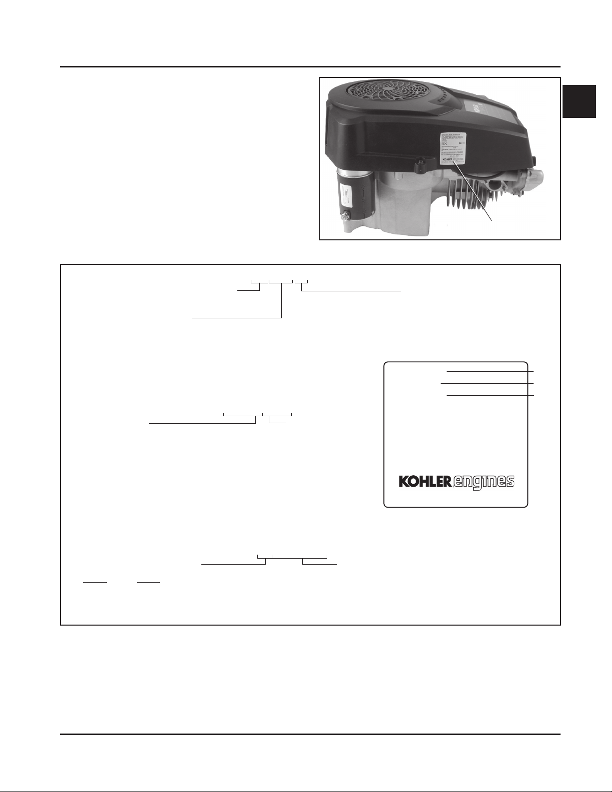
Engine Identification Numbers
When ordering parts, or in any communication
involving an engine, always give the Model,
Specification, and Serial Numbers of the engine.
The engine identification numbers appear on a decal
affixed to the engine shrouding. See Figure 1-1. An
explanation of these numbers is shown in Figure 1-2.
Section 1
Safety and General Information
1
Identification Decal
Figure 1-1. Engine Identification Decal Location.
A. Model No.
Courage™ Vertical Shaf t Engine
Numerical Designation
B. Spec. No.
Engine Model
Model
SV470
SV480
SV530
SV540
SV590
SV600
C. Serial No.
Year Manufactured Code
Code Year
32 2002
33 2003
34 2004
SV 540 S
SV540-0001
3205810334
First spec
written in this
model series
Factory Code
Version Code
S = Electric St art
MODEL NO.
SPEC. NO.
SERIAL NO.
REFER TO OWNER'S MANUAL FOR
SAFETY, MAINTENANCE SPECS
AND ADJUSTMENTS. FOR SALES
AND SERVICE IN US/CANADA
CALL: 1-800-544-2444.
www.kohlerengines.com
KOHLER CO. KOHLER, WI USA
A
B
C
Figure 1-2. Explanation of Engine Identification Numbers.
www.mymowerparts.com
1.3

Kohler Engine Parts Call K&T 606-678-9623 or 606-561-4983
Section 1
Safety and General Information
Oil Recommendations
Using the proper type and weight of oil in the
crankcase is extremely important, as is checking oil
daily and changing oil regularly . Failure to use the
correct oil or using dirty oil causes premature engine
wear and failure.
Oil T ype
Use high-quality detergent oil of API (American
Petroleum Institute) service class SG, SH, SJ or
higher. Select the viscosity based on the air
temperature at the time of operation as shown below.
**
*Use of synthetic oil having 5W-20 or 5W-30 rating is acceptable,
up to 4°C (40°F).
**Synthetic oils will provide better starting in extreme cold below
-23°C (-10°F).
***30 weight acceptable above 0°C (32°F).
***
*
Fuel Recommendations
WARNING: Explosive Fuel!
Gasoline is extremely flammable and its vapors can
explode if ignited. Store gasoline only in approved
containers, in well ventilated, unoccupied buildings,
away from sparks or flames. Do not fill the fuel tank
while the engine is hot or running, since spilled fuel
could ignite if it comes in contact with hot parts or
sparks from ignition. Do not start the engine near
spilled fuel. Never use gasoline as a cleaning agent.
General Recommendations
Purchase gasoline in small quantities and store in
clean, approved containers. A cont ainer with a capacity
of 2 gallons or less with a pouring spout is
recommended. Such a container is easier to handle
and helps eliminate spillage during refueling.
Do not use gasoline left over from the previous
season, to minimize gum deposits in your fuel system
and to ensure easy starting.
Do not add oil to the gasoline.
Do not overfill the fuel tank. Leave room for the fuel to
expand.
NOTE: Using other than service class SG, SH, SJ or
higher oil or extending oil change intervals
longer than recommended can cause engine
damage.
A logo or symbol on oil cont ainers identifies the API
service class and SAE viscosity grade. See Figure 1-3.
Figure 1-3. Oil Container Logo.
Refer to Section 6 - “Lubrication System” for detailed
oil check, oil change, and oil filter change procedures.
Fuel Type
For best results, use only clean, fresh, unleaded
gasoline with a pump sticker octane rating of 87 or
higher. In countries using the Research method, it
should be 90 octane minimum.
Unleaded gasoline is recommended, as it leaves less
combustion chamber deposits. Leaded gasoline may
be used in areas where unleaded is not available and
exhaust emissions are not regulated. Be aware
however, that the cylinder head will require more
frequent service.
Gasoline/Alcohol blends
Gasohol (up to 10% ethyl alcohol, 90% unleaded
gasoline by volume) is approved as a fuel for Kohler
engines. Other gasoline/alcohol blends are not
approved.
Gasoline/Ether blends
Methyl Tertiary Butyl Ether (MTBE) and unleaded
gasoline blends (up to maximum of 15% MTBE by
volume) are approved as a fuel for Kohler engines.
Other gasoline/ether blends are not approved.
1.4
www.mymowerparts.com

Kohler Engine Parts Call K&T 606-678-9623 or 606-561-4983
Periodic Maintenance
Section 1
Safety and General Information
WARNING: Accident al Starts!
Disabling engine. Accidental starting can cause severe injury or death. Before working on the engine or
equipment, disable the engine as follows: 1) Disconnect the spark plug lead(s). 2) Disconnect negative (-)
battery cable from battery .
Maintenance Schedule
These required maintenance procedures should be performed at the frequency stated in the table. They should
also be included as part of any seasonal tune-up.
Maintenance RequiredFrequency
• Fill fuel tank.
Daily or Before
Starting Engine
Every 2 Months
or 25 Hours
Annually or
Every 100 Hours
Every 2 Y ears or
200 Hours
Every 200 Hours
Every 500 Hours
¹Perform these maintenance procedures more frequently under extremely dusty , dirty conditions.
²Have a Kohler Engine Service Dealer perform this service.
• Check oil level.
• Check air cleaner for dirty¹, loose, or damaged parts.
• Check air intake and cooling areas, clean as necessary¹.
• Service precleaner element¹ (if equipped).
• Service air cleaner element¹ (if not equipped with precleaner).
• Replace air cleaner element¹ (if equipped with precleaner).
• Change oil and filter (refer to Viscosity Table, Page 1.4, based on seasonal
temperatures).
• Remove blower housing and clean cooling areas.
• Check that all fasteners are in place and components are properly secured.
• Replace fuel filter .
• Check spark plug condition and gap.
• Have bendix starter drive serviced².
• Have valve lash checked/adjusted2.
• Replace spark plug.
1
Storage
If the engine will be out of service for two months or
more, use the following storage procedure:
1. Clean the exterior surfaces of the engine.
2. Change the oil and oil filter while the engine is still
warm from operation. See “Change Oil and Oil
Filter” in Section 6.
3. The fuel system must be completely emptied, or
the gasoline must be treated with a stabilizer to
prevent deterioration. If you choose to use a
stabilizer , follow the manufacturer’s
recommendations, and add the correct amount
for the capacity of the fuel system. Fill the fuel
tank with clean, fresh gasoline. Run the engine for
2-3 minutes to get stabilized fuel into the
carburetor.
To empty the system, run the engine until the tank
and system are empty .
4. Due to the deep recess around the spark plug,
blow out the cavity with compressed air. Remove
the spark plug. The spark plug is most accessible
when the blower housing is removed for cleaning.
Add one tablespoon of engine oil into the spark
plug hole. Install the plug, but do not connect the
plug lead. Crank the engine two or three
revolutions. Connect the plug lead.
5. Reinstall the blower housing, if removed
previously , and torque the blower housing screws
to 7.5 N·m (65 in. lb.).
6. Store the engine in a clean, dry place.
1.5
www.mymowerparts.com
Kohler Engine Parts Call K&T 606-678-9623 or 606-561-4983
Section 1
Safety and General Information
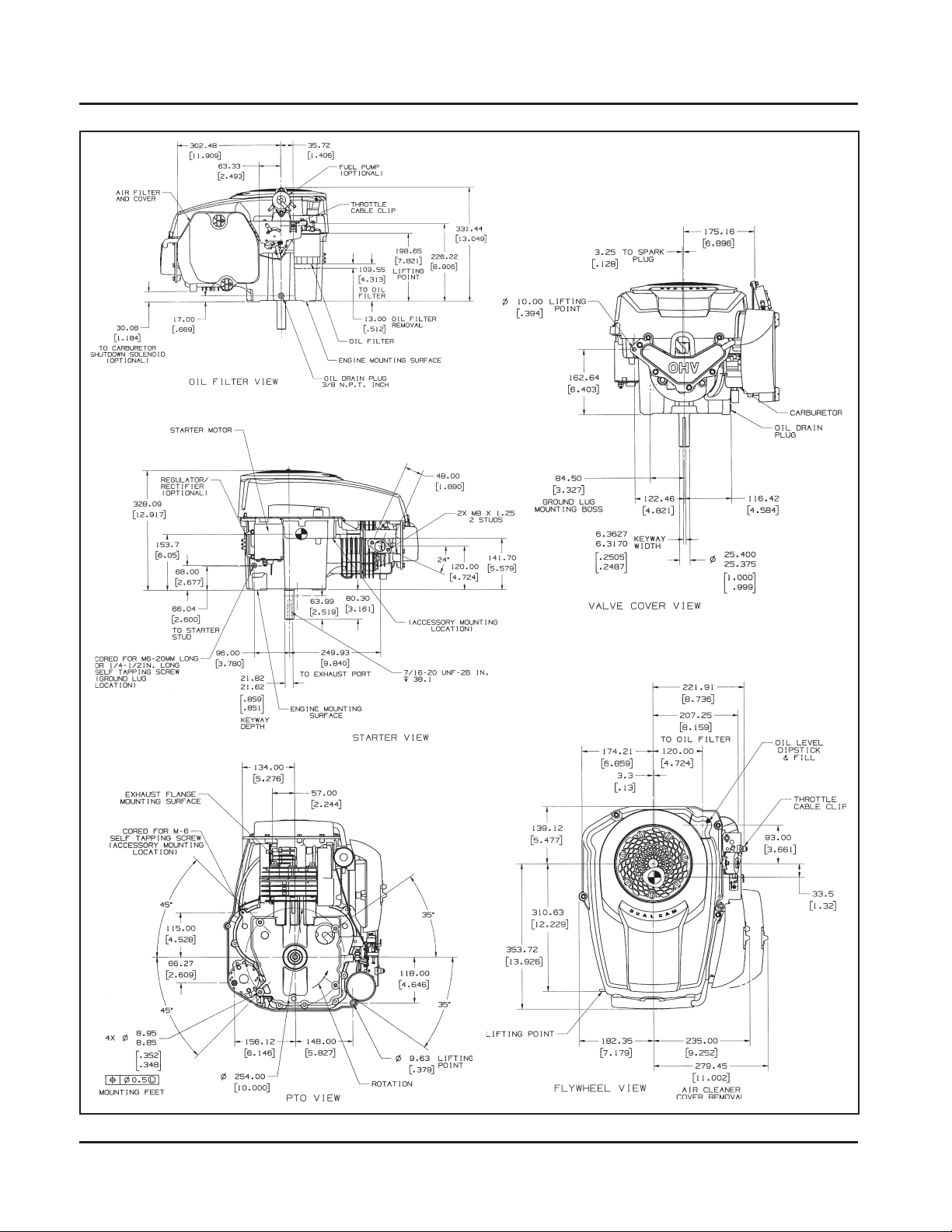
Dimensions in millimeters. Inch equivalents shown in ().
Figure 1-4. T ypical Engine Dimensions.
1.6
www.mymowerparts.com

Kohler Engine Parts Call K&T 606-678-9623 or 606-561-4983
Safety and General Information
General Specifications¹
Power (@ 3600 RPM, corrected to SAE J1940)
SV470 .................................................................................................11.2 kW (15 HP)
SV480 .................................................................................................11.9 kW (16 HP)
SV530 .................................................................................................12.7 kW (17 HP)
SV540 .................................................................................................13.4 kW (18 HP)
SV590 .................................................................................................14.1 kW (19 HP)
SV600 .................................................................................................14.9 kW (20 HP)
Peak T orque
SV470 @ 2600 RPM ............................................................................34.3 N·m (25.0 ft. lb.)
SV480 @ 2800 RPM ............................................................................34.6 N·m (25.5 ft. lb.)
SV530 @ 2600 RPM ............................................................................37.8 N·m (27.9 ft. lb.)
SV540 @ 2800 RPM ............................................................................39.1 N·m (29.0 ft. lb.)
SV590 @ 2600 RPM ............................................................................42.3 N·m (31.2 ft. lb.)
SV600 @ 2800 RPM ............................................................................44.2 N·m (32.0 ft. lb.)
Bore
SV470S, SV480S.................................................................................84 mm (3.30 in.)
SV530S, SV540S.................................................................................89 mm (3.50 in.)
SV590S, SV600S.................................................................................94 mm (3.70 in.)
Section 1
1
Stroke .........................................................................................................86 mm (3.38 in.)
Displacement
SV470S, SV480S.................................................................................477 cc (29.1 cu. in.)
SV530S, SV540S.................................................................................535 cc (32.6 cu. in.)
SV590S, SV600S.................................................................................597 cc (36.4 cu. in.)
Compr ession Ratio......................................................................................8.5:1
Dry Weight..................................................................................................35.8 kg (79 lb.)
Oil Capacity (with filter) ..............................................................................1.5 L (1.6 qt.)
Angle of Operation - Maximum (at Full Oil Level) All Directions....................25° Intermittent
Air Cleaner Base
Hex. Nut Fastener T orque ...........................................................................5.5 N·m (48 in. lb.)
Mounting Screw Fastener T orque (Inst all Dry - DO NOT OIL).......................8.0 N·m (70 in. lb.) Into new as-cast hole
5.5 N·m (48 in. lb.) Into used hole
Blower Housing and Sheet Metal
M6 Fasteners T or que ..................................................................................7.5 N·m (65 in. lb.)
Cam Lever
Cam Lever Fastener T orque.........................................................................7.5 N·m (65 in. lb.)
Cam Gears
End Play .....................................................................................................0.5/1.5 mm (0.019/0.059 in.)
Running Side Clearance ..............................................................................0.02/0.13 mm (0.001/0.005 in.)
1
V alues are in Metric units. Values in parentheses are English equivalent s. Lubricate threads with engine oil prior to
assembly , EXCEPT for air cleaner base thread forming screw - inst all dry.
1.7
www.mymowerparts.com

Kohler Engine Parts Call K&T 606-678-9623 or 606-561-4983
Section 1
Safety and General Information
Cam Gears (cont'd.)
Cam Gear-to-Cam Shaft Running Assembly ............................................. 0.02/0.10 mm (0.001/0.004 in.)
Carburetor
Fuel Bowl Retaining Screw T orque ........................................................... 5.1-6.2 N·m (45-55 in. lb.)
Closure Plate
Closure Plate Fastener T orque ................................................................ 24.5 N·m (216 in. lb.)
Balance Weight Guide Channel Width
New.................................................................................................. 17.95/18.05 mm (0.707/0.711 in.)
Max. Wear Limit ............................................................................... 18.13 mm (0.714 in.)
Connecting Rod
Cap Fastener T orque (torque in 2 increment s) ......................................... 5.5, 1 1.5 N·m (50, 100 in. lb.)
Connecting Rod-to-Crankpin Running Clearance
New................................................................................................... 0.03/0.055 mm (0.0012/0.0022 in.)
Max. Wear Limit ................................................................................ 0.07 mm (0.0025 in.)
Connecting Rod-to-Crankpin Side Clearance ............................................ 0.25/0.59 mm (0.0098/0.0232 in.)
Connecting Rod-to-Piston Pin Running Clearance .................................... 0.015/0.028 mm (0.0006/0.0011 in.)
Piston Pin End I.D.
New................................................................................................... 22.015/22.023 mm (0.8667/0.8670 in.)
Max. Wear Limit ................................................................................ 22.036 mm (0.8675 in.)
Crankcase
Governor Cross Shaft Bore I.D.
New................................................................................................... 6.025/6.05 mm (0.2372/0.2382 in.)
Max. Wear Limit ................................................................................ 6.063 mm (0.2387 in.)
Oil Drain Plug T orque ............................................................................... 14.0 N·m (125 in. lb.)
Crankshaft
End Play (free) ......................................................................................... 0.225/1.025 mm (0.0089/0.040 in.)
Crankshaft Bore in Crankcase I.D.
New.................................................................................................. 41.965/41.990 mm (1.6521/1.6531 in.)
Max. Wear Limit ............................................................................... 42.016 mm (1.654 in.)
Crankshaft Bore in Closure Plate I.D
New.................................................................................................. 44.965/44.990 mm (1.7703/1.7713 in.)
Max. Wear Limit ............................................................................... 45.016 mm (1.7723 in.)
Flywheel End Main Bearing Journal
O.D. – New....................................................................................... 44.913/44.935 mm (1.7682/1.7691 in.)
O.D. – Max. Wear Limit.................................................................... 44.84 mm (1.765 in.)
Max. T aper........................................................................................ 0.0220 mm (0.0009 in.)
Max. Out of Round............................................................................ 0.025 mm (0.001 in.)
1.8
www.mymowerparts.com

Kohler Engine Parts Call K&T 606-678-9623 or 606-561-4983
Section 1
Safety and General Information
Crankshaft (cont'd.)
PTO End Main Bearing Journal
O.D. – New....................................................................................... 41.913/41.935 mm (1.6501/1.6510 in.)
O.D. – Max. Wear Limit.................................................................... 41.86 mm (1.648 in.)
Max. T aper........................................................................................ 0.020 mm (0.0008 in.)
Max. Out of Round............................................................................ 0.025 mm (0.001 in.)
Crankshaft Bore in Closure Plate Running Clearance
New.................................................................................................. 0.03/0.077 mm (0.0012/0.003 in.)
Crankshaft Bore in Crankcase Running Clearance
New.................................................................................................. 0.03/0.077 mm (0.0012/0.003 in.)
Connecting Rod Journal O.D.
New.................................................................................................. 40.982/41.000 mm (1.6134/1.6141 in.)
Max. Wear Limit............................................................................... 40.964 mm (1.612 in.)
Max. Taper ....................................................................................... 0.012 mm (0.0005 in.)
Max. Out of Round ........................................................................... 0.025 mm (0.001 in.)
1
Crankshaft T.I.R.
PTO End, Crankshaft in Engine ....................................................... 0.15 mm (0.0059 in.)
Entire Crankshaft, in V -Blocks.......................................................... 0.10 mm (0.0039 in.)
Crankshaft Eccentrics O.D.
New.................................................................................................. 66.940/66.970 mm (2.6354/2.6366 in.)
Max. Wear Limit............................................................................... 66.89 mm (2.633 in.)
Balance Weight Bearing Surface I.D.
New.................................................................................................. 67.011/67.086 mm (2.6382/2.6412 in.)
Max. Wear Limit............................................................................... 67.140 mm (2.6430 in.)
Balance Weight Screw Torque................................................................ 10.0 N·m (90 in. lb.)
Guide Pin O.D.
New.................................................................................................. 1 1.950/11.975 mm (0.4705/0.4715 in.)
Max. Wear Limit............................................................................... 11.900 mm (0.4685 in.)
Guide Shoe Width
New.................................................................................................. 17.85/17.90 mm (0.703/0.705)
Max. Wear Limit............................................................................... 17.75 mm (0.6988 in.)
Guide Shoe Hole I.D.
New.................................................................................................. 12.000/12.025 mm (0.4724/0.4734 in.)
Max. Wear Limit ............................................................................... 12.050 mm (0.4744 in.)
Cylinder Bore
Cylinder Bore I.D.
New
SV470, SV480 ................................................................................ 84.000/84.025 mm (3.307/3.308 in.)
SV530, SV540 ................................................................................ 89.000/89.025 mm (3.504/3.505 in.)
SV590, SV600 ................................................................................ 94.010/94.035 mm (3.701/3.702 in.)
Max. Wear Limit
SV470, SV480 ................................................................................ 84.073 mm (3.310 in.)
SV530, SV540 ................................................................................ 89.073 mm (3.507 in.)
SV590, SV600 ................................................................................ 94.073 mm (3.704 in.)
www.mymowerparts.com
1.9

Kohler Engine Parts Call K&T 606-678-9623 or 606-561-4983
Section 1
Safety and General Information
Cylinder Bore I.D. (cont'd.)
Max. Taper ....................................................................................... 0.05 mm (0.002 in.)
Max. Out of Round........................................................................... 0.12 mm (0.0047 in.)
Cylinder Head
Cylinder Head Fastener T orque (torque in 2 increments).......................... 20.5, 41.0 N·m (180, 360 in. lb.)
Max. Out-of-Flatness.............................................................................. 0.8 mm (0.003 in.)
Rocker Arm Pivot Stud Torque................................................................ 13.5 N·m (120 in. lb.)
Rocker Arm Adjustment Nut Set Screw .................................................. 5.5 N·m (50 in. lb.)
Electric Starter
Thru Bolt Torque..................................................................................... 3.3-3.9 N·m (30-35 in. lb.)
Mounting Nut Torque .............................................................................. 3.6 N·m (32 in. lb.)
Nut (Top) Positive (+) Brush Lead Terminal ............................................ 1.6-2.8 N·m (15-25 in. lb.)
Nut (Flange) Positive (+) Brush Lead Terminal ....................................... 2.2-4.5 N·m (20-40 in. lb.)
Fan/Flywheel
Flywheel Retaining Screw Torque........................................................... 66.5 N·m (588 in. lb.)
Governor
Governor Cross Shaft-to-Crankcase Running Clearance ....................... 0.013/0.075 mm (0.0005/0.003 in.)
Governor Cross Shaft O.D.
New.................................................................................................. 5.975/6.012 mm (0.2352/0.2367 in.)
Max. Wear Limit............................................................................... 5.962 mm (0.2347 in.)
Governor Gear Shaft-to-Governor Gear Running Clearance.................. 0.09/0.16 mm (0.0035/0.0063 in.)
Governor Gear Shaft O.D.
New.................................................................................................. 5.99/6.00 mm (0.2358/0.2362 in.)
Max. Wear Limit............................................................................... 5.977 mm (0.02353 in.)
Ignition
Spark Plug Type (Champion
Sp ark Plug Gap ...................................................................................... 0.76 mm (0.030 in.)
Sp ark Plug Torque .................................................................................. 24-30 N·m (18-22 ft. lb.)
Ignition Module Air Gap .......................................................................... 0.203/0.305 mm (0.008/0.012 in.)
®
or Equivalent)............................................. RC12YC or QC12YC
Ignition Module Fastener T orque.............................................................. 6.0 N·m (55 in. lb.) Into new as-cast hole
4.0 N·m (35 in. lb.) Into used hole
Muffler
Muffler Retaining Nuts Torque ................................................................ 24.4 N·m (216 in. lb.)
Oil Filter
Oil Filter Torque ...................................................................................... 10-13 N·m (90-110 in. lb.)
1.10
www.mymowerparts.com

Kohler Engine Parts Call K&T 606-678-9623 or 606-561-4983
Section 1
Safety and General Information
Oil Filter Pad Pipe Plug
1/8” N.P .T.F . Torque ................................................................................. 4.5-5.0 N·m (40-46 in. lb.)
Oil Pump
Mounting Screw Torque .......................................................................... 4.0 N·m (35 in. lb.)
Pump Gears-to-Crankcase Side Clearance............................................ 0.165/0.315 mm (0.0065/0.0124 in.)
Oil Sentry™
Pressure Switch T orque .......................................................................... 4.5-5.0 N·m (40-45 in. lb.)
Piston, Piston Rings, and Piston Pin
Piston Pin Bore I.D.
New.................................................................................................. 22.006/22.012 mm (0.8685/0.8666 in.)
Max. Wear Limit............................................................................... 22.025 mm (0.8671 in.)
Piston Pin O.D.
New.................................................................................................. 21.995/22.0 mm (0.8659/0.8661 in.)
Max. Wear Limit............................................................................... 21.994 mm (0.8658 in.)
1
Top Compression Ring-to-Groove Side Clearance ................................. 0.04 mm (0.0016 in.)
Middle Compression Ring-to-Groove Side Clearance ............................ 0.04 mm (0.0016 in.)
Top and Middle Compression Ring End Gap
New Bore
Top Ring ......................................................................................... 0.15/0.40 mm (0.006/0.016 in.)
Middle Ring .................................................................................... 0.30/0.55 mm (0.012/0.022 in.)
Used Bore (max.)............................................................................. 0.77 mm (0.030 in.)
Piston Thrust Face O.D.²
SV470, SV480
New ................................................................................................ 83.948/83.962 mm (3.3050/3.3056 in.)
Max. Wear Limit ............................................................................. 83.828 mm (3.3003 in.)
SV530, SV540
New ................................................................................................ 88.948/88.962 mm (3.5018/3.5024 in.)
Max. Wear Limit ............................................................................. 88.828 mm (3.4972 in.)
SV590, SV600
New ................................................................................................ 93.928/93.942 mm (3.6980/3.6985 in.)
Max. Wear Limit ............................................................................. 93.828 mm (3.6940 in.)
Piston Thrust Face-to-Cylinder Bore² Running Clearance
SV470, SV480, SV530, SV540 ........................................................ 0.0575 mm (0.0023 in.)
SV590, SV560.................................................................................. 0.0875 mm (0.0034 in.)
Rectifier-Regulator
Mounting Screw T orque........................................................................... 6.0 N·m (55 in. lb.) Into new as cast hole
4.0 N·m (35 in. lb.) Into used hole
Speed Control
Speed Control Bracket Assembly Fastener T orque.................................11.0 N·m (95 in. lb.) Into new as-cast hole
7.5 N·m (65 in. lb.) Into used hole
²Measure 8 mm (0.314 in.) above the bottom of the piston skirt at right angles to the piston pin.
1.11
www.mymowerparts.com

Kohler Engine Parts Call K&T 606-678-9623 or 606-561-4983
Section 1
Safety and General Information
Stator
St ator Mounting Screw T orque................................................................. 6.0 N·m (55 in. lb.) Into new as-cast hole
4.0 N·m (35 in. lb.) Into used hole
Throttle/Choke Controls
Governor Control Lever Fastener T orque .................................................. 7.0-8.5 N·m (60-75 in. lb.)
Valve Cover
V alve Cover Fastener T orque ................................................................... 11.0 N·m (95 in. lb.) Into new as-cast hole
7.5 N·m (65 in. lb.) Into used hole
Valves and Valve Lifters
V alve Lash³ ............................................................................................. 0.076 mm (0.003 in.)
Intake V alve Minimum Lift........................................................................ 8.9 mm (0.350 in.)
Exhaust V alve Minimum Lift .................................................................... 8.9 mm (0.350 in.)
Nominal V alve Seat Angle ....................................................................... 45°
Intake V alve Stem-to-V alve Guide Running Clearance.............................. 0.038/0.076 mm (0.0015/0.003 in.)
Exhaust V alve Stem-to-V alve Guide Running Clearance .......................... 0.050/0.88 mm (0.0020/0.0035 in.)
Intake V alve Guide I.D.
New .................................................................................................. 6.038/6.058 mm (0.2377/0.2385 in.)
Max. Wear Limit ............................................................................... 6.135 mm (0.2415 in.)
Intake V alve Stem Diameter
New .................................................................................................. 5.982/6.0 mm (0.2355/0.2362 in.)
Exhaust V alve Guide I.D.
New .................................................................................................. 6.038/6.058 mm (0.2377/0.2385 in.)
Max. Wear Limit ............................................................................... 6.160 mm (0.2425 in.)
Exhaust V alve Stem Diameter
New .................................................................................................. 5.970/5.988 mm (0.235/0.2357 in.)
³Check valve lash every 200 hours, adjust as required.
1.12
www.mymowerparts.com

Kohler Engine Parts Call K&T 606-678-9623 or 606-561-4983
Section 1
Safety and General Information
General Torque Values
Metric Fastener T orque Recommendations for St andard Applications
Tightening Torque: N·m (in. lb.) + or - 10%
Property Class
Noncritical
4.8
Size
M4 1.2 (1 1) 1.7 (15) 2.9 (26) 4.1 (36) 5.0 (44) 2.0 (18)
M5 2.5 (22) 3.2 (28) 5.8 (51) 8.1 (72) 9.7 (86) 4.0 (35)
M6 4.3 (38) 5.7 (50) 9.9 (88) 14.0 (124) 16.5 (146) 6.8 (60)
M8 10.5 (93) 13.6 (120) 24.4 (216) 33.9 (300) 40.7 (360) 17.0 (150)
Tightening Torque: N·m (ft. lb.) + or - 10%
5.8 8.8 10.9 12.9
Fasteners
Into Aluminum
1
Property Class
4.8
M10 21.7 (16) 27.1 (20) 47.5 (35) 66.4 (49) 81.4 (60) 33.9 (25)
M12 36.6 (27) 47.5 (35) 82.7 (61) 1 16.6 (86) 139.7 (103) 61.0 (45)
M14 58.3 (43) 76.4 (55) 131.5 (97) 184.4 (136) 219.7 (162) 94.9 (70)
5.8 8.8 10.9 12.9
Oil Drain Plugs Tightening Torque: N•m (English Equiv.)
Size
1/8" NPT
1/4"
3/8"
1/2"
3/4"
X-708-1
Into Cast Iron
–
17.0 (150 in. lb.)
20.3 (180 in. lb.)
27.1 (20 ft. lb.)
33.9 (25 ft. lb.)
27.1/33.9 (20/25 ft. lb.)
Into Aluminum
4.5 (40 in. lb.)
1 1.3 (100 in. lb.)
13.6 (120 in. lb.)
17.6 (13 ft. lb.)
21.7 (16 ft. lb.)
27.1/33.9 (20/25 ft. lb.)
Conversions
N·m = in. lb. x 0.1 13
N·m = ft. lb. x 1.356
in. lb. = N·m x 8.85
ft. lb. = N·m x 0.737
Noncritical
Fasteners
Into Aluminum
Torque
www.mymowerparts.com
1.13
Kohler Engine Parts Call K&T 606-678-9623 or 606-561-4983
Section 2
Special Tools
SV470-600
Section 2
Special Tools
Certain quality tools are designed to help you perform specific disassembly , repair , and reassembly procedures.
By using tools designed for the job, you can service engines easier, faster , and safer! In addition, you’ll increase
your service capabilities and customer satisfaction by decreasing engine downtime.
Kohler special tools are handled by SPX Corp., a division of Owatonna T ool Corp. (OTC). The tools are easy to
purchase by contacting SPX/OTC by phone, fax, or mail.
Phone: 1-800-533-0492
International: 1-507-455-7223
8:00 am – 8:00 pm EST
Some special tools for this engine are:
Flywheel Puller Kit ........................................................................................... NU3226
V alve Guide Reamer ......................................................................................... KO1026
Rocker Arm Spanner Wrench ........................................................................... (obtain locally)
Water Manometer ............................................................................................ KO1048
V acuum Gauge ................................................................................................ KO3223
Cylinder Leakdown T ester................................................................................. KO3219
Ignition System T ester...................................................................................... KO1046
Amp Meter ....................................................................................................... KO3218
Inductance T achometer .................................................................................... KO3216
Fax: 1-800-578-7375
1-586-578-7375
International: 1-507-455-7063
Mail: SPX Corp., OTC
28635 Mound Rd.
Warren, MI 48092-3499
2
Some of the specialty tools are shown and mentioned at various points in this manual. A complete catalog of all
available tools may be ordered under Kohler Part No. TP-2546. The tool price list is available under Kohler Part No.
TP-2547.
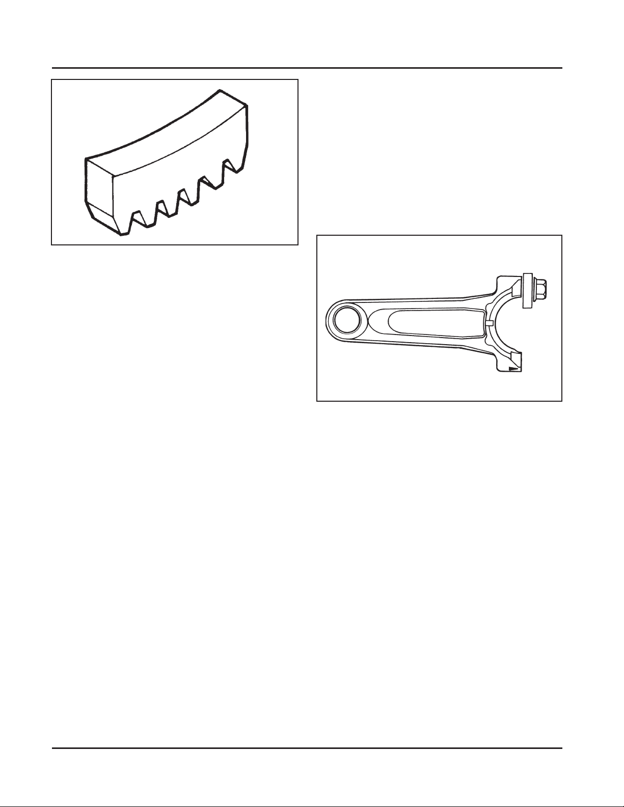
Special Tools You Can Make
Flywheel Holding Tool
Flywheel removal and reinstallation becomes a “snap”
using a handy holding tool you can make out of a piece
of an old “junk” flywheel ring gear as shown in Figure
2-2. Using an abrasive cut-off saw , cut out a six tooth
segment of the ring gear as shown. Grind off any burrs
or sharp edges. The segment can be used in place of a
strap wrench. Invert the segment and place it between
the ignition module bosses on the crankcase, so the
tool teeth engage the ring gear teeth on the flywheel.
The bosses will “lock” the tool and flywheel in position
Figure 2-1. Tool Catalog and Price List.
for loosening, tightening or removing with a puller.
2.1
www.mymowerparts.com
Kohler Engine Parts Call K&T 606-678-9623 or 606-561-4983
Section 2
Special Tools
Figure 2-2. Flywheel Holding Tool.
Rocker Arm/Crankshaft Tool
If you don’t have a spanner wrench to lift the rocker
arms or to turn the crankshaft, you can make a tool for
doing this out of an old junk connecting rod.
Find a used connecting rod from a 10 HP or larger
engine. Remove and discard the rod cap. If it is a PosiLock rod, you will also need to remove the studs. If it is
a Command rod, you will need to grind off the aligning
steps, so the joint surface is flat. Find a 1" long
capscrew with the correct thread size to match the
threads in the connecting rod. Obtain a flat washer
with the correct I.D. to slip on the capscrew and an
O.D. of approximately 1". Kohler Part No. 12 468 05-S
can be used if you don’t have the right size on hand.
Assemble the capscrew and washer to the joint
surface of the rod, as shown in Figure 2-3.
Figure 2-3. Rocker Arm/Crankshaf t T ool.
2.2
www.mymowerparts.com

Kohler Engine Parts Call K&T 606-678-9623 or 606-561-4983
Section 3
Troubleshooting
Troubleshooting Guide
When troubles occur, be sure to check the simple
causes which, at first, may seem too obvious to be
considered. For example, a starting problem could be
caused by an empty fuel tank.
Some common types of engine troubles are listed
below. Use these to help locate the possible cause(s).
Troubleshooting
Engine Will Not Crank
1. PTO drive is engaged.
2. Battery is discharged.
3. Safety interlock switch is engaged.
4. Loose or faulty wires or connections.
5. Faulty key switch or ignition switch.
6. Faulty electric starter .
7. Seized internal engine components.
Section 3
SV470-600
3
Engine Cranks But Will Not Start
1. Empty fuel tank.
2. Fuel shut-off valve closed.
3. Dirt or water in the fuel system.
4. Clogged fuel line.
5. Sp ark plug lead disconnected.
6. Key switch or kill switch in ‘‘off’’ position.
7. Faulty spark plug.
8. Faulty ignition module.
9. Inoperative fuel solenoid.
10. Choke not closing.
Engine Start s But Does Not Keep Running
1. Vent in fuel cap restricted.
2. Dirt or water in the fuel system.
3. Faulty choke or throttle controls.
4. Loose wires or connections that short the kill
terminal of ignition module to ground.
5. Faulty carburetor.
6. Faulty cylinder head gasket.
Engine Start s Hard
1. PTO drive is engaged.
2. Dirt or water in the fuel system.
3. Clogged fuel line.
4. Loose or faulty wires or connections.
5. Faulty choke or throttle controls.
6. Faulty spark plug.
7. Low compression.
8. Faulty ACR mechanism.
Engine Runs But Misses
1. Dirt or water in the fuel system.
2. S park plug faulty or fouled.
3. Spark plug lead boot loose on plug.
4. Loose wires or connections that intermittently
short the kill terminal of ignition module to ground.
5. Engine overheated.
6. Faulty ignition module or improperly gapped.
Engine Will Not Idle
1. Vent in fuel cap restricted.
2. Dirt or water in the fuel system.
3. Faulty spark plug.
4. Idle fuel adjusting needle improperly set.
5. Idle speed adjusting screw improperly set.
6. Low compression.
7. Stale fuel and/or gum in carburetor.
Engine Overheats
1. Air intake/grass screen, cooling fins, or cooling
shrouds clogged.
2. Excessive engine load.
3. Low crankcase oil level.
4. High crankcase oil level.
5. Faulty carburetor.
Engine Knocks
1. Excessive engine load.
2. Low crankcase oil level.
3. Old/improper fuel.
4. Internal wear or damage.
www.mymowerparts.com
3.1

Kohler Engine Parts Call K&T 606-678-9623 or 606-561-4983
Section 3
Troubleshooting
Engine Loses Power
1. Low crankcase oil level.
2. High crankcase oil level.
3. Dirty air cleaner element.
4. Dirt or water in the fuel system.
5. Excessive engine load.
6. Engine overheated.
7. Faulty spark plug.
8. Low compression.
9. Exhaust restriction.
Engine Uses Excessive Amount of Oil
1. Incorrect oil viscosity/type.
2. Breather clogged or inoperative.
3. Worn or broken piston rings.
4. Worn cylinder bore.
5. Worn valve stems/valve guides.
6. Crankcase overfilled.
External Engine Inspection
Before cleaning or disassembling the engine, make a
thorough inspection of its external appearance and
condition. This inspection can give clues to what might
be found inside the engine (and the cause) when it is
disassembled.
• Check for buildup of dirt and debris on the
crankcase, cooling fins, grass screen and other
external surfaces. Dirt or debris on these areas
can cause overheating.
• Check for obvious oil leaks and damaged
components. Excessive oil leakage can indicate a
clogged or inoperative breather, worn or damaged
seals or gaskets, or loose fasteners.
• Check the air cleaner cover and base for damage
or indications of improper fit and seal.
• Check the air cleaner element. Look for holes,
tears, cracked or damaged sealing surfaces, or
other damage that could allow unfiltered air into
the engine. Also note if the element is dirty or
clogged. These could indicate improper
maintenance.
• Check the carburetor throat for dirt. Dirt in the
throat is further indication that the air cleaner was
not functioning properly .
• Check if the oil level is within the operating range
on the dipstick. If it is above, sniff for gasoline
odor.
• Check the condition of the oil. Drain the oil into a
container; it should flow freely . Check for metal
chips and other foreign particles.
Sludge is a natural by-product of combustion; a small
accumulation is normal. Excessive sludge formation
could indicate the wrong type or weight of oil was
used, the oil was not changed at the recommended
intervals, an over-rich fuel mixture, or weak ignition, to
name a few possible causes.
NOTE: It is good practice to drain oil at a location
away from the workbench. Be sure to allow
ample time for complete drainage.
Cleaning the Engine
After inspecting the external condition of the engine,
clean the engine thoroughly before disassembling it.
Also clean individual components as the engine is
disassembled. Only clean parts can be accurately
inspected and gauged for wear or damage. There are
many commercially available cleaners that will quickly
remove grease, oil, and grime from engine parts.
When such a cleaner is used, follow the
manufacturer’s instructions and safety precautions
carefully.
Make sure all traces of the cleaner are removed
before the engine is reassembled and placed into
operation. Even small amounts of these cleaners can
quickly break down the lubricating properties of engine
oil.
3.2
www.mymowerparts.com

Kohler Engine Parts Call K&T 606-678-9623 or 606-561-4983
Section 3
Troubleshooting
Basic Engine Tests
Crankcase Vacuum Test
A p artial vacuum should be present in the crankcase
when the engine is operating. Pressure in the
crankcase (normally caused by a clogged or
improperly-operating breather) can cause oil to be
forced out at oil seals, gaskets, or other available
spots.
Crankcase vacuum is best measured with a water
manometer or vacuum/pressure test gauge. See
Section 2. Complete instructions are provided with the
testers.
Test the crankcase vacuum with the manometer as
follows:
1. Insert the rubber stopper into the oil fill hole. Be
sure the pinch clamp is installed on the hose and
use the tapered adapters to connect the hose
between the stopper and one of the manometer
tubes. Leave the other tube open to the
atmosphere. Check that the water level in the
manometer is at the “0” line. Make sure the pinch
clamp is closed.
2. Start the engine and run at no-load high idle speed
(3200 to 3750 RPM).
3. Open the clamp and note the water level in the
tube.
The level in the engine side should be a minimum
of 10.2 cm (4 in.) above the level in the open side.
If the level in the engine side is the same as the
open side (no vacuum), or the level in the engine
side is lower than the level in the open side
(pressure), check for the conditions in the table
below.
4. Close the pinch clamp before stopping the engine.
To perform the test with the vacuum/pressure gauge:
1. Insert the stopper as in step 1.
2. Insert the barbed gauge fitting into the hole in the
stopper. Be sure the gauge needle is at “0”.
3. Run the engine, as in step 2, and observe the
gauge reading. Needle movement to the left of “0”
is a vacuum, and movement to the right indicates
a pressure. A minimum of 10.2 cm (4 in.) of
vacuum should be present.
3
Incorrect Vacuum in Crankcase
Possible Cause Solution
1. Crankcase breather clogged or inoperative.
2. Seals and/or gaskets leaking. Loose or
improperly torqued fasteners.
3. Piston blowby or leaky valves. Confirm with
cylinder leakdown test.
4. Restricted exhaust.
1. Disassemble breather, clean p arts thoroughly ,
reassemble, and recheck pressure.
2. Replace all worn or damaged seals and
gaskets. Make sure all fasteners are tightened
securely . Use appropriate torque values and
sequences when necessary .
3. Recondition piston, rings, cylinder bore, valves,
and valve guides.
4. Repair/replace restricted muffler/exhaust
system.
www.mymowerparts.com
3.3

Kohler Engine Parts Call K&T 606-678-9623 or 606-561-4983
Section 3
Troubleshooting
Compression T est
These engines are equipped with an automatic
compression release (ACR) mechanism. Because of
the ACR mechanism, it is dif ficult to obt ain an accurate
compression reading. As an alternate, use the
leakdown test described below.
Cylinder Leakdown T est
A cylinder leakdown test can be a valuable alternative
to a compression test. By pressurizing the combustion
chamber from an external air source, you can
determine if the valves or rings are leaking, and how
badly .
SPX Part No. KO3219 (previously Kohler Part No.
25 761 05-S) is a relatively simple, inexpensive
leakdown tester for small engines. The tester includes
a quick disconnect coupling for attaching the adapter
hose and a holding tool.
Leakdown T est Instructions
1. Run the engine for 3-5 minutes to warm it up.
2. Remove the spark plug.
3. Rotate the crankshaft until the piston is at top
dead center of the compression stroke. You will
need to hold the engine in this position while
testing. The holding tool supplied with the tester
can be used if the PTO end of the crankshaft is
accessible. Slide the holding tool onto the
crankshaft, align the slot with one of the mounting
holes on the PTO face, and tighten it onto the
crankshaft. Install a 3/8" breaker bar into the slot
of the holding tool, so it is perpendicular to both
the holding tool and crankshaft, or insert a
shoulder bolt through the slot and thread it into
the mounting hole. If the flywheel end is more
accessible, you can use a breaker bar and socket
on the flywheel nut/screw to hold it in position. You
may need an assistant to hold the breaker bar
during testing. If the engine is mounted in a piece
of equipment, you may be able to hold it by
clamping or wedging a driven component. Just be
certain that the engine cannot rotate off of TDC in
either direction.
4. Install the adapter into the spark plug hole, but do
not attach it to the tester at this time.
5. Connect an adequate air source (80-100 psi) to
the tester.
6. Turn the regulator knob in the increase
(clockwise) direction until the gauge needle is in
the yellow ‘‘set’’ area at the low (right) end of the
scale.
7. Connect the tester quick-disconnect to the
adapter. Note the gauge reading and listen for
escaping air at the carburetor inlet, exhaust outlet,
and/or crankcase breather.
8. Check your test results against the table below:
Leakdown T est Result s
Air escaping from crankcase breather .......................................... Defective rings or worn cylinder walls.
Air escaping from exhaust system................................................ Defective exhaust valve.
Air escaping from carburetor ........................................................Defective intake valve.
Gauge reading in ‘‘low’’ (green) zone............................................ Piston rings and cylinder in good condition.
Gauge reading in ‘‘moderate’’ (yellow) zone.................................. Engine is still usable, but there is some wear
present. Customer should start planning for
overhaul or replacement.
Gauge reading in ‘‘high’’ (red) zone .............................................. Rings and/or cylinder have considerable wear.
Engine should be reconditioned or replaced.
3.4
www.mymowerparts.com

Kohler Engine Parts Call K&T 606-678-9623 or 606-561-4983
Section 4
Air Cleaner and Air Intake System
SV470-600
Section 4
Air Cleaner and Air Intake System
Air Cleaner
These engines are equipped with a replaceable, high
density , paper air cleaner element. Some engines also
have an oiled, foam precleaner, located in the outer air
cleaner cover. See Figure 4-1.
Air Cleaner
Base
Optional Foam Precleaner
Intake air is drawn in through the upper opening from
the blower housing, passes through the precleaner (if
so equipped), the paper element and then into the
carburetor. The outer air cleaner cover is secured by
two knobs, and removed by turning the knobs
counterclockwise.
Air Cleaner Element
Air Cleaner Cover
4
Figure 4-1. Air Cleaner Assembly - Exploded View .
Check the air cleaner daily or before starting the
engine. Check for and correct any buildup of dirt and
debris, and loose or damaged components.
NOTE: Operating the engine with loose or damaged
air cleaner components could allow unfiltered
air into the engine causing premature wear
and failure.
www.mymowerparts.com
Air
Cleaner
Cover
Knobs
Precleaner Service
If so equipped, wash and oil the precleaner every two
months or every 25 hours of operation (more often
under extremely dusty or dirty conditions).
1. Loosen the air cleaner cover knobs and remove
the cover.
2. Remove the precleaner.
4.1

Kohler Engine Parts Call K&T 606-678-9623 or 606-561-4983
Section 4
Air Cleaner and Air Intake System
3. Wash the precleaner in warm water with
detergent. Rinse the precleaner thoroughly until
all traces of detergent are eliminated. Squeeze
out excess water (do not wring). Allow the
precleaner to air dry .
4. Saturate the precleaner with new engine oil.
Squeeze out all excess oil.
5. Reinstall the precleaner into the outer cover .
6. Install the air cleaner cover and secure with the
two knobs.
7. When precleaner replacement is necessary , order
Kohler Part No. 20 083 01-S.
Paper Element Service
Check the paper element every two months or every
25 hours of operation (more often under extremely
dusty or dirty conditions). Clean or replace the element
as necessary . Replace the air cleaner element
annually or every 100 hours.
1. Remove the air cleaner cover and the precleaner
(if so equipped), service as required.
2. Remove the air cleaner element with the integral
rubber seal.
8. When element replacement is necessary , order
Kohler Part No. 20 083 02-S.
Inspect Air Cleaner Components
Whenever the air cleaner cover is removed, or the
paper element or precleaner is serviced, check the
following areas/components:
Outer Air Cleaner Cover - Make sure the air cleaner
cover is in good condition, not cracked, damaged, or
missing a retaining knob, which can affect the sealing
ability of the air cleaner element.
Air Cleaner Base - Make sure the base is properly
secured and not cracked or damaged. Since the air
cleaner base and carburetor are secured to the intake
port with common hardware, it is extremely important
that the fasteners securing these components are tight
at all times. The air cleaner base also provides the
mounting points for the air cleaner cover retaining
studs. Make sure the bosses are not cracked, broken
or damaged, and the studs are properly secured.
Before reinstalling an air cleaner base that has been
removed, make sure the metal bushings in the base
mounting holes are present. See Figure 4-2. The
bushings prevent damage to the base and maintain
the proper mounting torque.
3. Gently tap the pleated side of the paper element
to dislodge dirt. Do not wash the paper element
or use pressurized air, as this will damage the
element. Replace a dirty , bent, or damaged
element with a genuine Kohler element. Handle
new elements carefully; do not use if the rubber
seal is damaged.
4. Clean all air cleaner components of any
accumulated dirt or foreign material. Prevent any
dirt from entering the throat of the carburetor.
5. Install the air cleaner element with the pleated
side “out” and seat the rubber seal onto the edges
of the air cleaner base.
6. Reinstall the precleaner (if so equipped), into the
upper section of the air cleaner cover. Make sure
the hole in the precleaner is aligned with the
upper mounting knob. See Figure 9.
7. Reinstall the air cleaner cover and secure with the
two knobs.
Figure 4-2. Bushings in Air Cleaner Base.
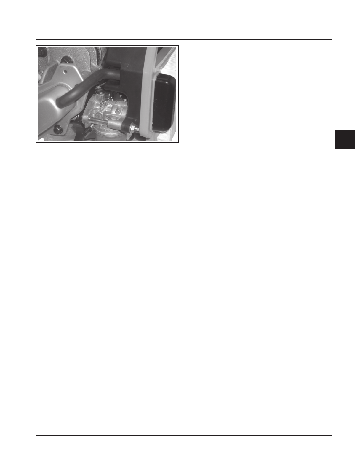
Breather Hose - Make sure the hose is not cracked or
damaged, and attached to both the air cleaner base
and valve cover.
NOTE: Damaged, worn, or loose air cleaner
components can allow unfiltered air into the
engine causing premature wear and failure.
Tighten or replace all loose or damaged
components.
4.2
www.mymowerparts.com
Kohler Engine Parts Call K&T 606-678-9623 or 606-561-4983
Figure 4-3. Breather Hose.
Disassembly
The following procedure is for complete disassembly
of all air cleaner components. As the removal of the air
cleaner base also affects carburetor mounting and
governor adjustment, steps 3 and 4 should only be
performed if required. Detailed photos are provided in
Sections 5, 8, and 10 for the various individual steps.
Section 4
Air Cleaner and Air Intake System
Reassembly
The following procedure is for complete assembly of
all air cleaner components. S teps 1-3 are necessary
only if the air cleaner base and/or the cover mounting
studs were removed in “Disassembly”.
1. Install the mounting studs into the air cleaner
base if removed previously . T ighten the studs until
bottomed, or to the end of threads (do not force).
2. Install the air cleaner base gasket and air cleaner
base, with the two metal spacers, onto the
mounting stud(s) and/or alignment pin. Make sure
the upper mounting tab is located above the
closure plate. Install and finger tighten the hex.
flange nut(s). When a long M6 thread forming
mounting screw is used, apply hand pressure to
keep the parts from shifting, then remove the
alignment pin and install the M6 thread forming
screw. DO NOT OIL. Torque the nut(s) to 5.5 N·m
(48 in. lb.). Torque the screw to 8.0 N·m
(70 in. lb.) into a new hole, or 5.5 N·m (48 in. lb.)
into a used hole, do not over tighten.
4
1. Loosen the air cleaner cover retaining knobs and
remove the air cleaner cover.
2. Remove the foam precleaner (if so equipped),
and the air cleaner element with formed rubber
seal.
3. Disconnect the breather hose from the valve
cover or air cleaner base.
NOTE: The air cleaner base should be removed
only if necessary .
4. Remove the two hex. flange nuts from the
mounting studs. If one stud and one thread
forming screw is used; first remove the thread
forming screw on the right side of the carburetor
inlet, which secures the air cleaner base,
carburetor and gaskets. Insert a 3/16” diameter
rod approximately 4” long, into the hole to serve
as a temporary alignment pin. Be careful not to
force the rod or damage the threads. Then
remove the hex. flange nut from the stud on the
left side of the carburetor inlet. Carefully remove
the air cleaner base and gasket. The cover
mounting studs thread into the air cleaner base,
and they should only be removed if necessary .
3. Reconnect the breather hose and perform the
governor adjustment (See Section 5, “Initial
Governor Adjustment”).
4. Install the air cleaner element with the pleated
side “out” and seat the rubber seal onto the edges
of the air cleaner base.
5. Install the serviced precleaner (if so equipped)
into the air cleaner cover. Make sure the hole in
the precleaner is aligned with the upper mounting
knob.
6. Reinstall the air cleaner cover and secure with the
two knobs.
www.mymowerparts.com
4.3

Kohler Engine Parts Call K&T 606-678-9623 or 606-561-4983
Section 4
Air Cleaner and Air Intake System
Air Intake/Cooling System
Clean Air Intake/Cooling Areas
To ensure proper cooling, make sure the grass screen,
cooling fins, and other external surfaces of the engine
are kept clean at all times.
Annually or every 100 hours of operation, (more often
under extremely dusty , dirty conditions), remove the
blower housing and any other cooling shrouds. Clean
the cooling fins and external surfaces as necessary .
Make sure all parts are reinstalled. Torque the M6
blower housing fasteners to 7.5 N·m (65 in. lb.).
NOTE: Operating the engine with a blocked grass
screen, dirty or plugged cooling fins, and/or
cooling shrouds removed, will cause engine
damage due to overheating.
4.4
www.mymowerparts.com

Kohler Engine Parts Call K&T 606-678-9623 or 606-561-4983
Section 5
Fuel System and Governor
SV470-600
Section 5
Fuel System and Governor
Fuel Recommendations
WARNING: Explosive Fuel!
Gasoline is extremely flammable and its vapors can
explode if ignited. Store gasoline only in approved
containers, in well-ventilated, unoccupied buildings,
away from sparks or flames. Do not fill the fuel tank
while the engine is hot or running, since spilled fuel
could ignite if it comes in contact with hot parts or
sparks from ignition. Do not start the engine near
spilled fuel. Never use gasoline as a cleaning agent.
General Recommendations
Purchase gasoline in small quantities and store in
clean, approved containers. A cont ainer with a capacity
of 2 gallons or less with a pouring spout is
recommended. Such a container is easier to handle
and helps eliminate spillage during refueling.
Do not use gasoline left over from the previous
season, to minimize gum deposits in your fuel system
and to insure easy starting.
Do not add oil to the gasoline.
Gasoline/Alcohol blends
Gasohol (up to 10% ethyl alcohol, 90% unleaded
gasoline by volume) is approved as a fuel for Kohler
engines. Other gasoline/alcohol blends are not
approved.
Gasoline/Ether blends
Methyl Tertiary Butyl Ether (MTBE) and unleaded
gasoline blends (up to a maximum of 15% MTBE by
volume) are approved as a fuel for Kohler engines.
Other gasoline/ether blends are not approved.
Fuel System
The typical fuel system and related components
include the fuel tank, in-line fuel filter , fuel pump,
carburetor, and fuel lines. Some applications use
gravity feed without a fuel pump.
Operation
The fuel from the tank is moved through the in-line
filter and fuel lines by the fuel pump. On engines not
equipped with a fuel pump, the fuel tank outlet is
located above the carburetor inlet and gravity moves
the fuel.
5
Do not overfill the fuel tank. Leave room for the fuel to
expand.
Fuel Type
For best results, use only clean, fresh, unleaded
gasoline with a pump sticker octane rating of 87 or
higher. In countries using the Research method, it
should be 90 octane minimum.
Unleaded gasoline is recommended, as it leaves less
combustion chamber deposits. Leaded gasoline may
be used in areas where unleaded is not available and
exhaust emissions are not regulated. Be aware
however, that the cylinder head will require more
frequent service.
www.mymowerparts.com
Fuel then enters the carburetor float bowl and is
moved into the carburetor body . There, the fuel is
mixed with air. This fuel-air mixture is then burned in
the engine combustion chamber.
Troubleshooting
Use the following procedure to check if fuel is reaching
the combustion chamber.
5.1

Kohler Engine Parts Call K&T 606-678-9623 or 606-561-4983
Section 5
Fuel System and Governor
Fuel System Troubleshooting Guide
T est Conclusion
1. Check for the following:
a. Make sure the fuel tank contains clean, fresh,
proper fuel.
b. Make sure the vent in fuel cap is open.
c. Make sure the fuel valve is open.
2. Check for fuel in the combustion chamber.
a. Disconnect and ground spark plug lead.
b. Close the choke on the carburetor.
c. Crank the engine several times.
d. Remove the spark plug and check for fuel at
the tip.
3. Check for fuel flow from the tank to the fuel pump.
a. Remove the fuel line from the inlet fitting of
the fuel pump.
b. Hold the line below the bottom of the tank.
Open the shutoff valve (if so equipped) and
observe flow.
4. Check the operation of fuel pump.
a. Remove the fuel line from the inlet fitting of
the carburetor.
b. Crank the engine several times and observe
flow.
2. If there is fuel at the tip of the spark plug, fuel is
reaching the combustion chamber.
If there is no fuel at the tip of the spark plug, check
for fuel flow from the fuel tank (Test 3).
3. If fuel does flow from the line, reconnect line and
check for faulty fuel pump (Test 4).
If fuel does not flow from the line, check for
clogged fuel tank vent, fuel pickup screen, shutoff
valve, and fuel lines.
4. If fuel does flow from the line, check for faulty
carburetor. (Refer to the "Carburetor" portions of
this section.)
If fuel does not flow from the line, check for
clogged fuel line. If the fuel line is unobstructed, the
fuel pump is faulty and must be replaced.
Fuel Filter
Some engines are equipped with an in-line fuel filter.
Periodically inspect the filter and replace when dirty .
Replacement is recommended annually or every 100
hours. Use a genuine Kohler filter.
Fuel Pump
Some engines are equipped with an optional pulse fuel
pump. See Figure 5-1.
Operation
The fuel pump has two internal chambers separated
by a diaphragm. The air chamber is connected to the
engine crankcase by a rubber hose. The fuel chamber
has an inlet from the fuel tank, and an outlet to the
carburetor. The inlet and outlet each have an internal,
one-way check valve.
Alternating negative and positive pressures in the
crankcase activate the pump. When the piston moves
upward in the cylinder, negative pressure (vacuum) is
created in the crankcase and in the air chamber of the
pump. The diaphragm flexes toward the negative
pressure, and the suction draws fuel past the inlet
check valve, into the fuel chamber. Downward
movement of the piston causes a positive pressure in
the crankcase and air chamber, pushing the
diaphragm in the opposite direction, putting pressure
on the fuel. The inlet check valve has now closed, so
the fuel is forced past the outlet check valve, to the
carburetor.
Repair
Pulse fuel pumps are not serviceable and must be
replaced when faulty .
Removal
1. Disconnect the inlet, outlet, and pulse lines from
the fuel pump. Mark the lines for proper
reassembly.
2. Remove the hex. flange screws attaching the fuel
pump.
Installation
1. Install the new fuel pump, and secure with the
hex. flange screws. Torque the hex. flange screws
to 5.9 N·m (52 in. lb.). Do not over tighten.
2. Connect the inlet, outlet, and pulse lines to their
respective fittings on pump. Secure with the
clamps. See Figure 5-1.
5.2
www.mymowerparts.com
Kohler Engine Parts Call K&T 606-678-9623 or 606-561-4983
Figure 5-1. Pulse Fuel Pump.
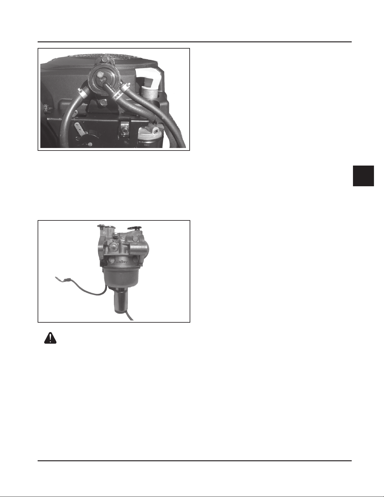
Carburetor
These engines are equipped with a Walbro fixed main
jet carburetor. See Figure 5-2. The carburetors will
have a low idle speed adjustment screw, and either
fixed idle, or a limiter cap on the idle fuel adjustment
needle.
Section 5
Fuel System and Governor
Troubleshooting – Fuel System
If engine troubles are experienced that appear to be
fuel system related, check the following areas before
adjusting or disassembling the carburetor.
• Make sure the fuel tank is filled with clean, fresh
gasoline.
• Make sure the fuel cap vent is not blocked and
that it is operating properly .
• Make sure fuel is reaching the carburetor. This
includes checking the fuel shut-off valve, fuel tank
filter screen, in-line fuel filter, fuel lines, and fuel
pump (as equipped), for restrictions or faulty
components.
• Make sure the air cleaner base and carburetor
are securely fastened to the engine using gaskets
in good condition.
• Make sure the air cleaner element is clean, and
all air cleaner components are fastened securely .
5
Figure 5-2. Carburetor.
WARNING: Explosive Fuel
Gasoline is extremely flammable and its vapors can
explode if ignited. Store gasoline only in approved
containers, in well ventilated, unoccupied buildings,
away from sparks or flames. Do not fill the fuel tank
while the engine is hot or running, since spilled fuel
could ignite if it comes in contact with hot parts or
sparks from ignition. Do not start the engine near
spilled fuel. Never use gasoline as a cleaning agent.
• Make sure the ignition system, governor system,
exhaust system, and throttle and choke controls
are operating properly .
If, after checking the items listed above, starting
problems or conditions similar to those listed in the
following table exist, it may be necessary to adjust or
service the carburetor.
www.mymowerparts.com
5.3
Kohler Engine Parts Call K&T 606-678-9623 or 606-561-4983
Section 5
Fuel System and Governor
Troubleshooting – Fuel System
Condition
1. Engine starts hard, runs roughly or
stalls at idle speed.
2. Engine runs rich. (Indicated by
black, sooty exhaust smoke,
misfiring, loss of speed and power,
governor hunting, or excessive
throttle opening).
3. Engine runs lean. (Indicated by
misfiring, loss of speed and power,
governor hunting, or excessive
throttle opening).
4. Fuel leaks from carburetor. 4a. Float level set too high. See Remedy 2c.
1a. Low idle fuel mixture/speed improperly adjusted. Adjust the low idle
speed screw, then adjust the low idle fuel needle.
b. Improper choke adjustment.
2a. Choke partially closed during operation. Check the choke lever/
linkage to ensure choke is operating properly .
b. Low idle fuel mixture is improperly adjusted. Adjust low idle fuel
needle.
c. Float level is set too high. With fuel bowl removed and carburetor
inverted, the exposed surface of float must be parallel with the
bowl gasket surface of the carburetor body .
d. Dirt under fuel inlet needle. Remove needle; clean needle and
seat and blow with compressed air.
e. Bowl vent or air bleeds plugged. Remove fuel bowl, low idle fuel
adjusting needle, and welch plugs. Clean vent, ports, and air
bleeds. Blow out all passages with compressed air .
f. Fuel bowl gasket leaks. Remove fuel bowl and replace gasket.
g. Leaky , cracked, or damaged float. Submerge float to check for
leaks.
3a. Low idle fuel mixture is improperly adjusted. Adjust low idle fuel
needle.
b. Float level is set too low. With fuel bowl removed and carburetor
inverted, the exposed surface of float must be parallel with the
bowl gasket surface of the carburetor body .
c. Idle holes plugged; dirt in fuel delivery channels. Remove fuel
bowl, low idle fuel adjusting needle, and welch plugs. Clean main
fuel jet and all passages; blow out with compressed air .
b. Dirt under fuel inlet needle. See Remedy 2d.
c. Bowl vent plugged. Remove fuel bowl and clean bowl vent. Blow
out with compressed air.
d. Float is cracked or damaged. Replace float.
e. Bowl retaining screw gasket damaged. Replace gasket.
f. Bowl retaining screw loose. Torque screw to specifications.
Possible Cause/Probable Remedy
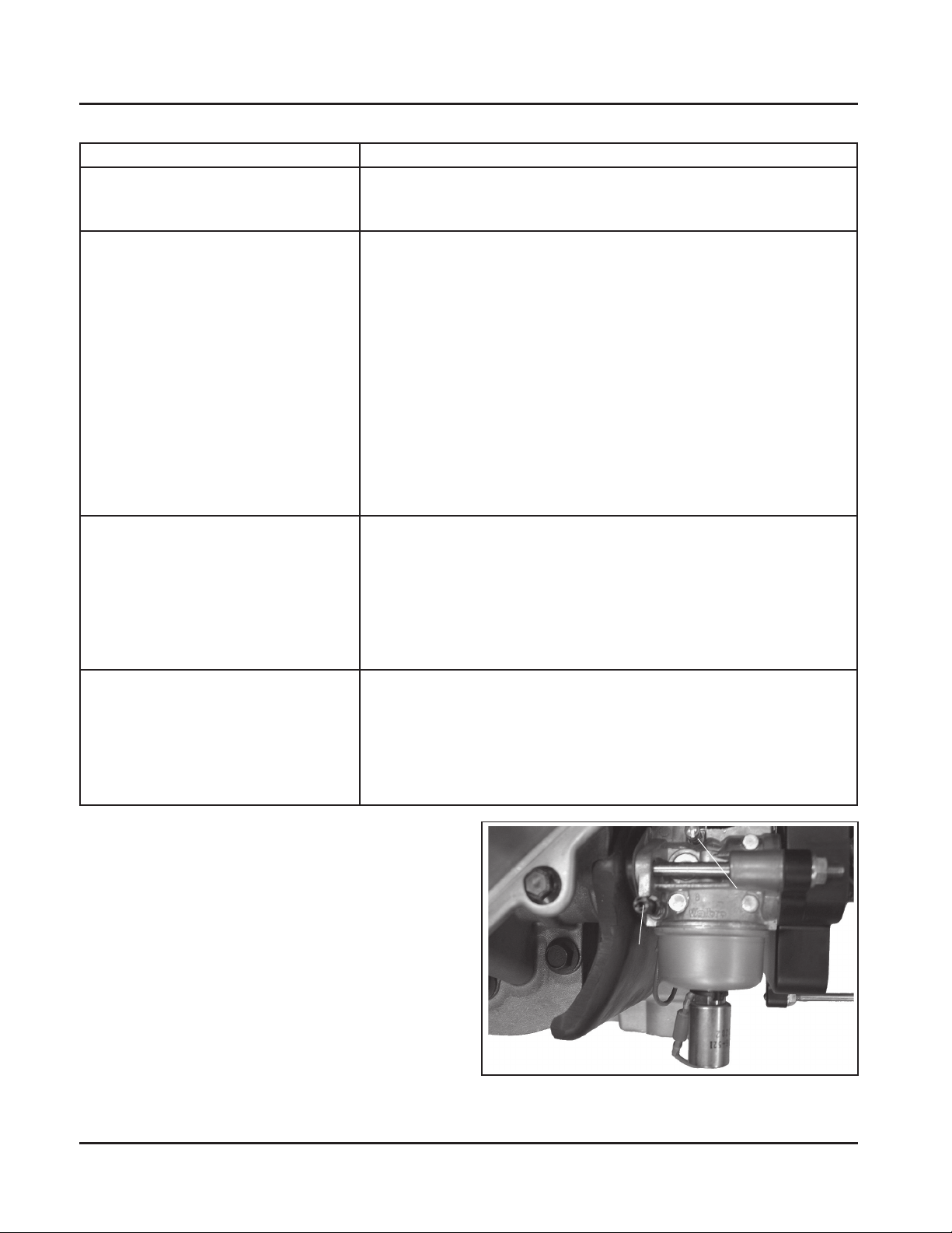
Carburetor Adjustment
NOTE: Carburetor adjustments should be made only
after the engine has warmed up.
The carburetor is designed to deliver the correct fuelto-air mixture to the engine under all operating
conditions. The main fuel jet is calibrated at the factory
and is not adjustable*. The idle fuel adjustment needle
is also set at the factory and normally does not need
adjustment. If the engine is hard starting or does not
operate properly , however , it may be necessary to
adjust or service the carburetor.
*NOTE: Engines operating at altitudes above
approximately 1830 m (6000 ft.) may require
a special ”high altitude” main jet. Refer to
“High Altitude Operation” later in this section.
5.4
www.mymowerparts.com
Idle Speed (RPM)
Adjustment Screw
Idle Fuel
Mixture Needle
Figure 5-3. Fixed Main Jet Carburetor.
Kohler Engine Parts Call K&T 606-678-9623 or 606-561-4983
Section 5
Fuel System and Governor
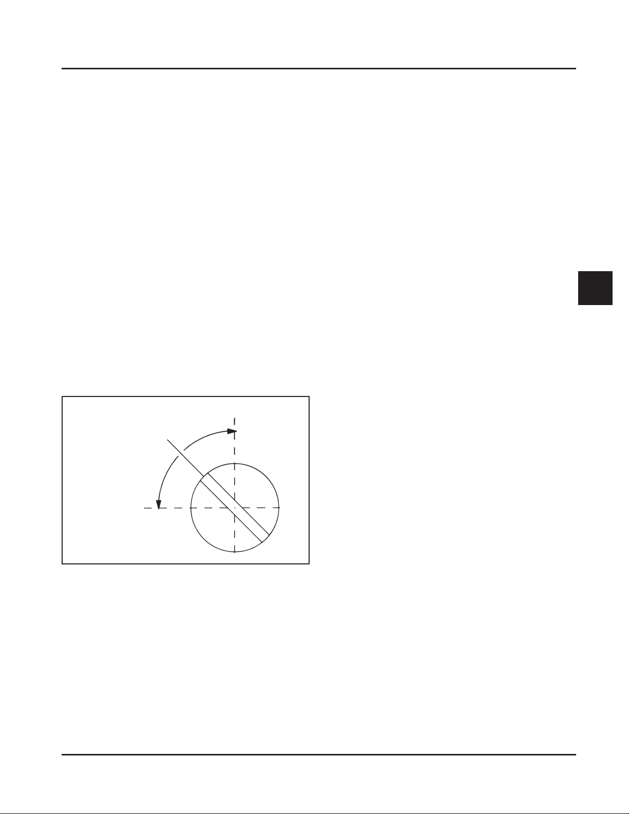
Low Idle Mixture Adjustment*
NOTE: Engines will have fixed idle (no adjustment
possible) or a limiter cap on the idle fuel
adjustment needle. Step 2 can only be
performed within the limits allowed by the cap.
1. St art the engine and run at half throttle for 5 to 10
minutes to warm up. The engine must be warm
before doing steps 2 and 3.
2. Low Idle Fuel Needle Setting: Place the throttle
into the “idle” or “slow” position.
Turn the low idle fuel adjustment needle out
(counterclockwise) from the preliminary setting
until engine speed decreases (rich). Note the
position of the needle.
Now turn the adjusting needle in (clockwise). The
engine speed may increase, then it will decrease
as the needle is turned in (lean). Note the position
of the needle.
Set the adjusting needle midway between the rich
and lean settings. See Figure 5-4.
Low Idle Speed Setting
1. Start the engine and run at half throttle for 5 to 10
minutes to warm up. The engine must be warm
before doing step 2.
2. Low Idle Speed Setting: Place the throttle
control into the “idle” or “slow” position. Set the
low idle speed by turning the low idle speed
adjusting screw in or out. Check the speed using
a tachometer.
*NOTE: The actual low idle speed depends on
the application–refer to equipment
manufacturer’s recommendations. The
recommended low idle speed for basic
engines is 1500 RPM. To ensure best
results when setting the low idle fuel
needle, the low idle speed must not
exceed 1500 RPM (±75 RPM).
5
Lean
Adjust to Midpoint
Rich
Figure 5-4. Optimum Low Idle Fuel Setting.
*NOTE: If the engine is equipped with a governed idle
adjustment (See Figure 5-19), the governor
will compensate for speed changes due to the
low idle mixture adjustment. Disable the
governed idle control by backing out the
governed idle adjusting screw and setting a
fixed idle speed using the idle speed screw
on the carburetor. Make the low idle mixture
adjustment and then reset the governed idle
speed at the adjusting screw.
www.mymowerparts.com
5.5
 Loading...