

Page 1

Installation Guide
Toilet
K-3900
M product numbers are for Mexico (i.e. K-12345M)
Los números de productos seguidos de M corresponden a México
(Ej. K-12345M)
Français, page “Français-1”
Español, página “Español-1”
1132336-2-D
Page 2
Important Information
NOTE: This product is designed for installation with the electrical and water supplies located through
either the wall or the floor.
Grounding Instructions
•
This product should be grounded. In the event of an electrical short circuit, grounding reduces the
risk of electric shock by providing an escape wire for the electric current. This product is equipped
with a cord having a grounding wire with a grounding plug. The plug must be plugged into an
outlet that is properly installed and grounded.
WARNING: Risk of electric shock. Improper use of the grounding plug can result in a risk of
electric shock.
•
If repair or replacement of the cord or plug is necessary, do not connect the grounding wire to either
flat blade terminal. The wire with insulation having an outer surface that is green with or without
yellow stripes is the grounding wire.
•
Check with a qualified electrician or service personnel if the grounding instructions are not
completely understood, or if in doubt as to whether the product is properly grounded.
•
This product is factory equipped with a specific electric cord and plug to permit connection to a
proper electric circuit. Make sure that the product is connected to an outlet having the same
configuration as the plug. No adapter should be used with this product. Do not modify the plug
provided — if it will not fit the outlet, have the proper outlet installed by a qualified electrician. If
the product must be reconnected for use on a different type of electric circuit, the connection should
be made by qualified service personnel.
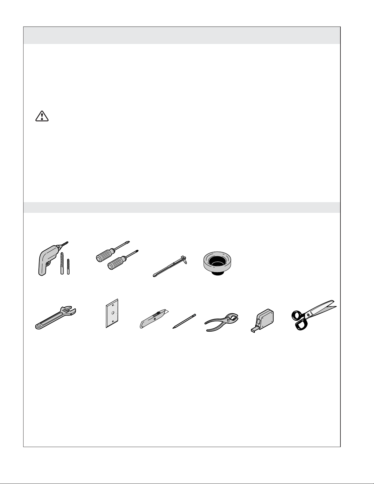
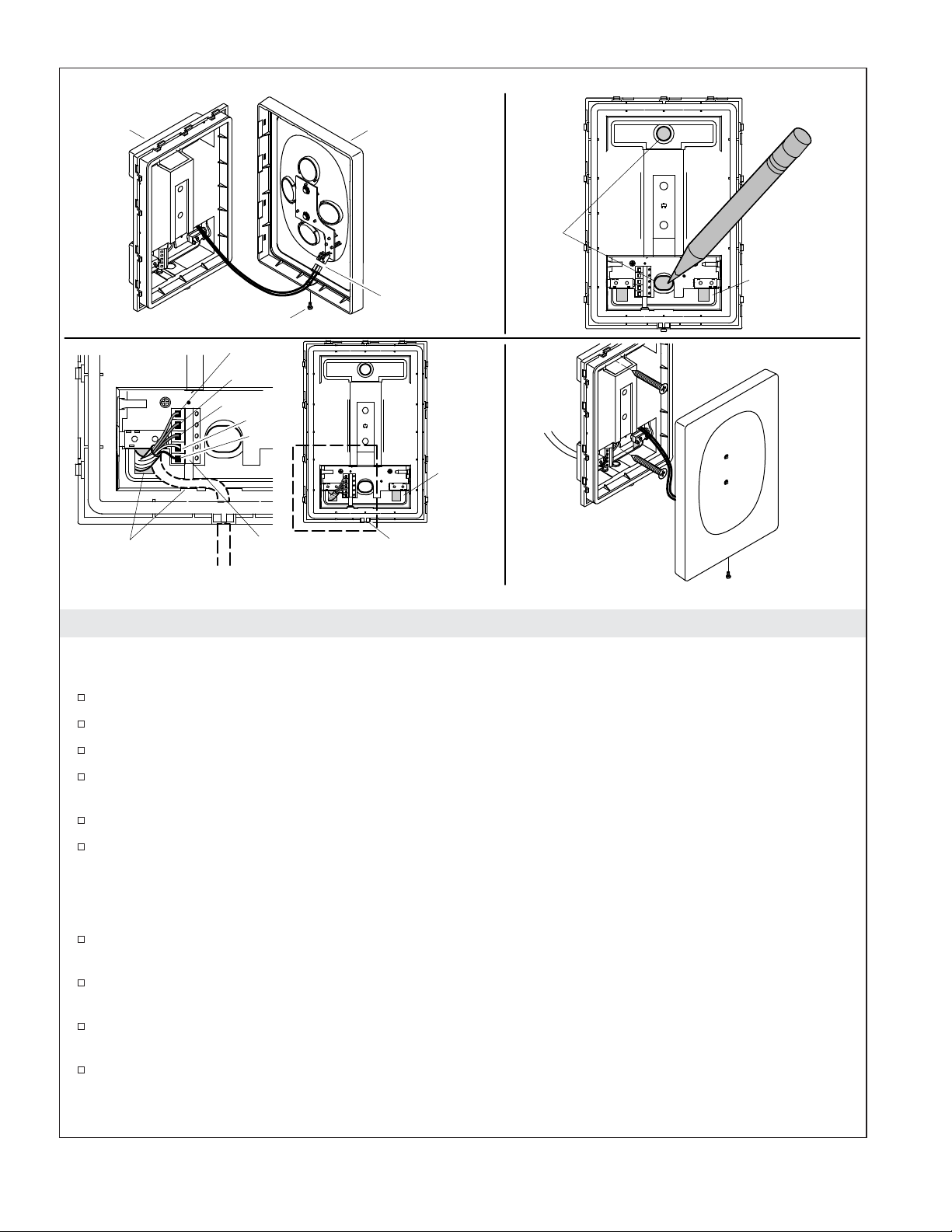
Tools and Materials
Drill with Assorted Bits
Adjustable Wrench
Assorted
Screwdrivers
Wall Plate
Offset Screwdriver
Plus:
• Protective Material
• Tape
• Water Hammer Arrestor
Wax Ring
1132336-2-D 2 Kohler Co.
Page 3

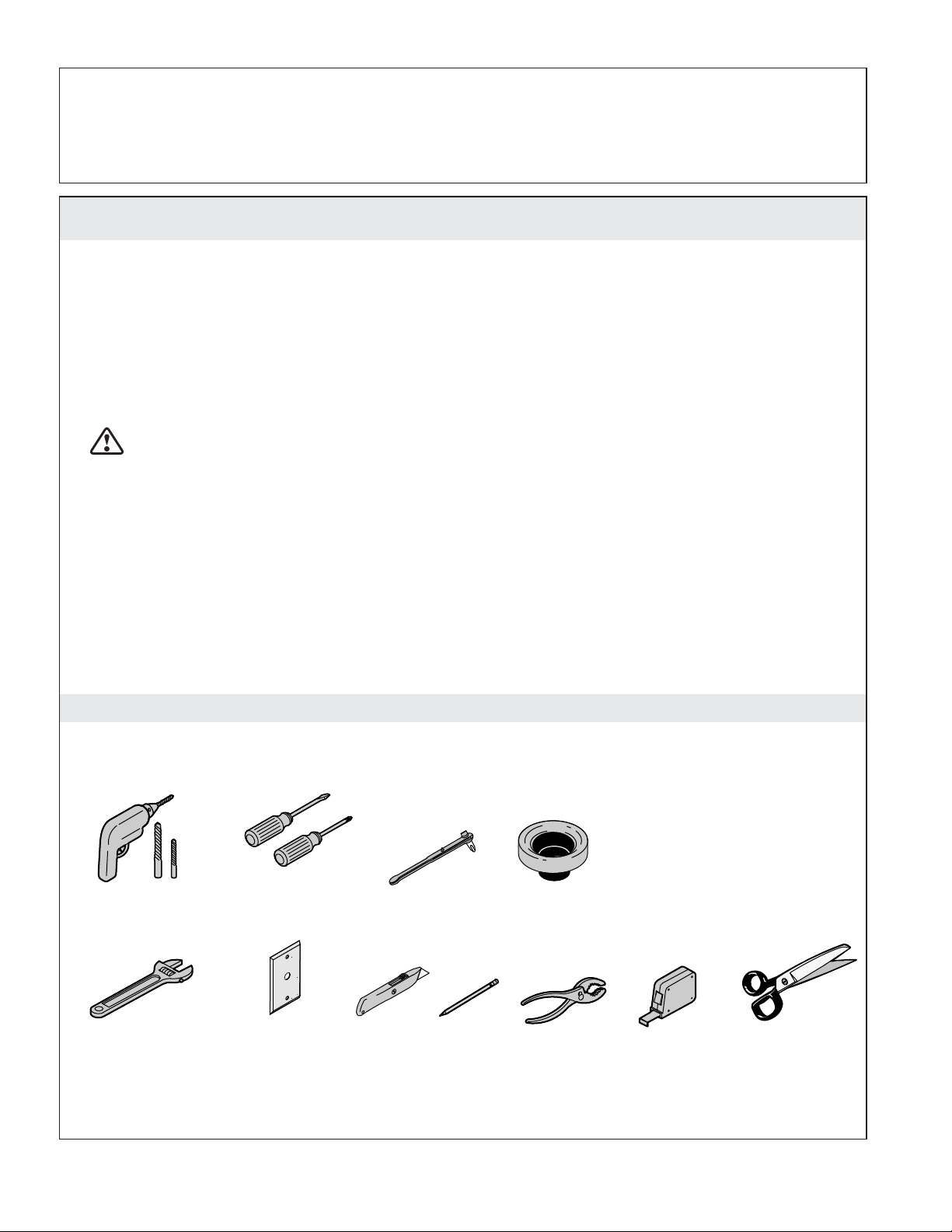
(4) 5/16" x 2-1/2" Lag Bolts
Parts Bag Contents
2 Caps
2 Bushings
(4) 5/16" Lag Bolt Anchors
Docking
Station
Remote Control
Before You Begin
WARNING: Risk of electric shock. Disconnect power before servicing.
WARNING: Risk of electric shock. For plug-in installations/wall-mounted electrical supply:
Connect only to a properly-grounded, grounding-type receptacle which is protected by a 120 V, 15
A minimum, 60 Hz Ground-Fault Circuit-Interrupter (GFCI) or Residual Current Device (RCD). Do
not remove the grounding pin or use a grounding adapter.
2 Mounting Blocks
Other Parts
Back Cover
(Through-the-Floor
Installations)
Supply Hose
2 #10 x 1-1/2"
Screws
Clip
CAUTION: Risk of personal injury. This toilet weighs approximately 100 lbs (45 kg). Lift the toilet
with two people, employing proper lifting technique.
CAUTION: Risk of hazardous gases. If a new toilet is not installed immediately, temporarily place
a rag in the floor flange opening.
CAUTION: Risk of property damage. This toilet is not intended to be installed in buildings where
temperatures will drop below 32°F (0°C). The design of the toilet makes it difficult to remove all
water from the tank. If frozen, the water could damage the tank resulting in leaking.
NOTICE: Follow all local plumbing and electrical codes.
IMPORTANT! This product requires a minimum static pressure of 30 psi (206.8 kPa) for satisfactory rim
wash performance.
Carefully inspect the new toilet for damage.
Consult the online users guide at kohler.com for more information.
Kohler Co. reserves the right to make revisions in the design of products without notice, as specified
in the Price Book.
Confirm all parts below are included before beginning the installation.
Kohler Co. 3 1132336-2-D
Page 4
Before You Begin (cont.)
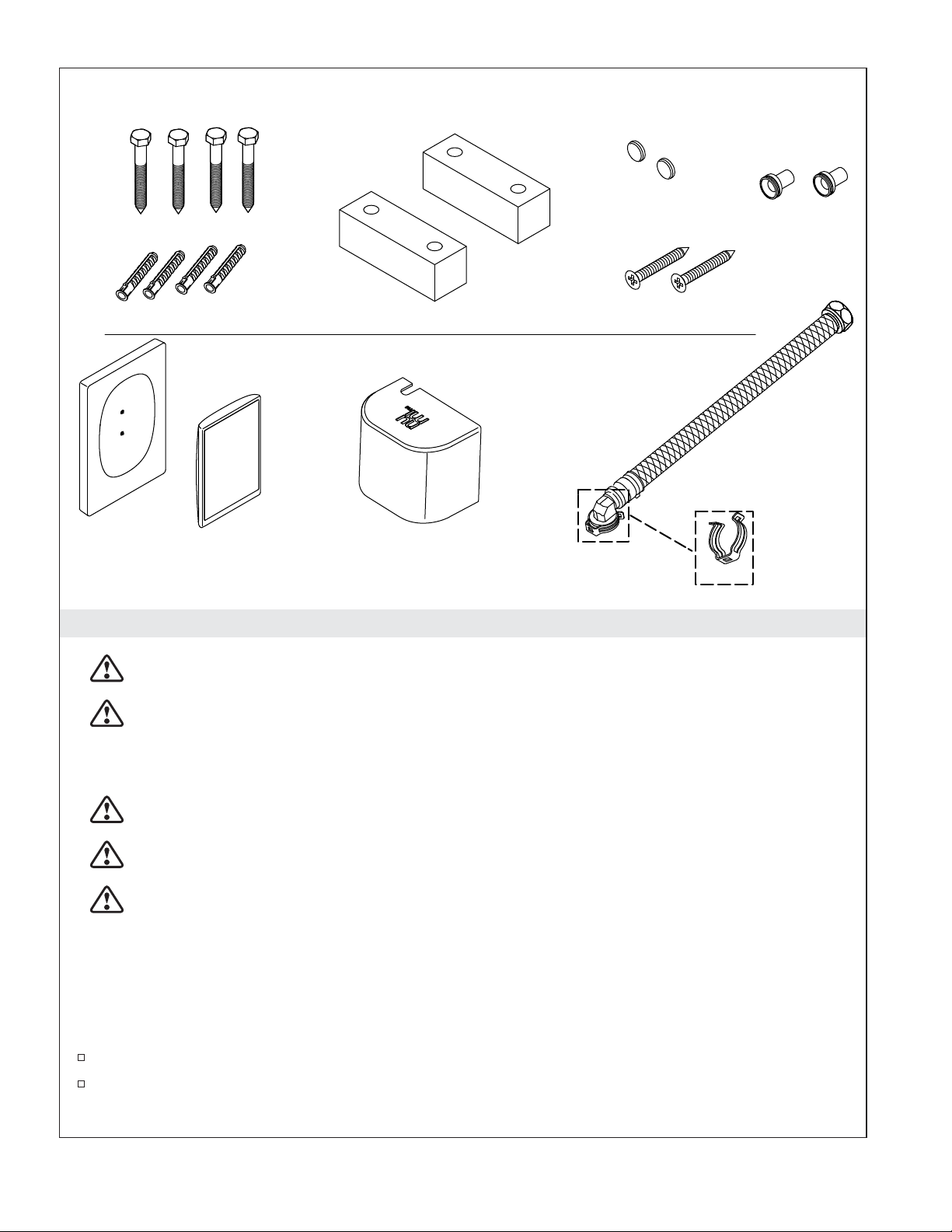
Parts Bag Contents
(4) 5/16″ x 2-1/2″ Lag Bolts
(4) 5/16″ Lag Bolt Anchors
2 Mounting Blocks
2 Plastic Caps
2 #10 x 1-1/2″ Screws
2 Bushings
Remote Control Box Contents
Docking Station
Remote Control
Docking Station Power Cord (not shown)
FM External Antenna (not shown)
AUX In Audio Cord (not shown)
Other Parts
Back Cover (used in through-the-floor installations)
Supply Hose
Clip
1132336-2-D 4 Kohler Co.
Page 5

29-1/2" (749 mm)
3-3/4" (95 mm),
3-9/16" (90 mm) Min
Front of Bowl
10-13/16" (275 mm)
4-3/4" (121 mm)
Optional
Supply,
1/2" OD
Compression
Outlet Thread
1-3/4"
(44 mm),
1-1/2"
(38 mm)
Min
36-1/4"
(921 mm)
12" (305 mm)
25-3/4"
(654 mm)
38" (965 mm) - 66" (1676 mm)
5-15/16"
(151 mm)
C
C
L Of Outlet
14-1/2"
(368 mm)
4-1/16"
(104 mm)
15-5/8"
(397 mm)
Optional Supply
1/2" OD Compression
Outlet Thread
Docking Station
2-1/4"
(57 mm)
41" (1041 mm) -
66" (1676 mm)
13-5/8"
(346 mm)
1/2" OD
Compression
Outlet Thread
6"
(152 mm)
8" (203 mm)
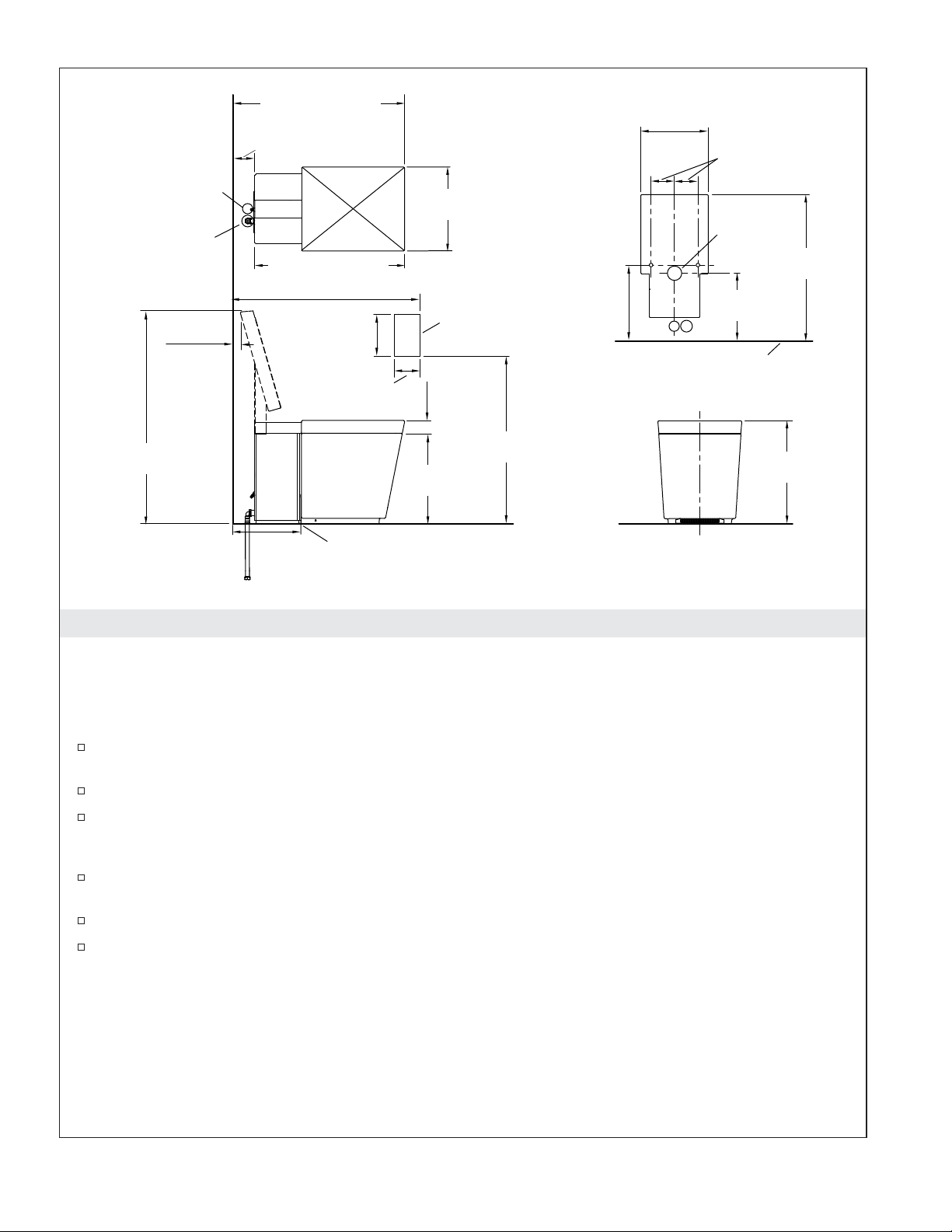
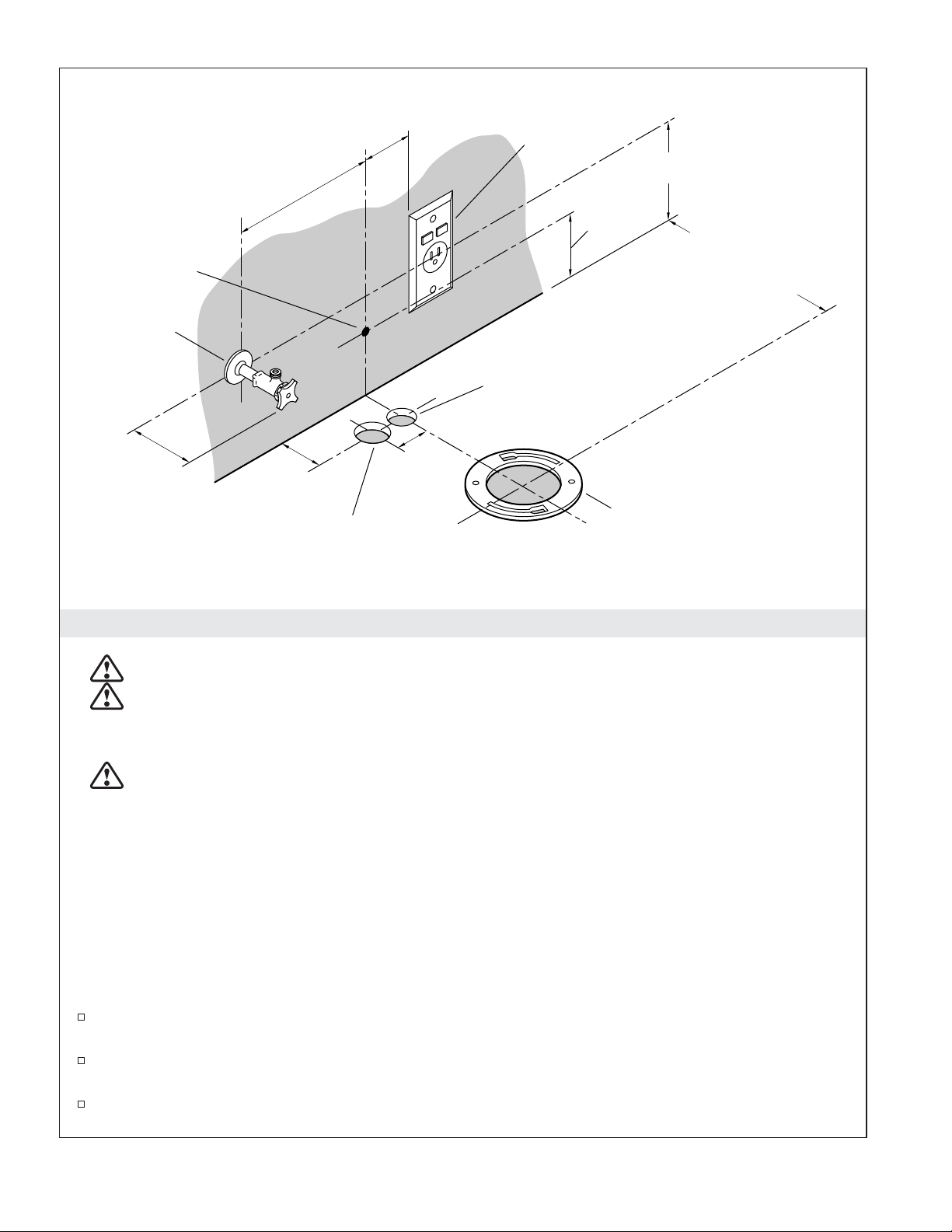
Roughing-in - Wall Mount Electrical and Water Supply
Ø 2-5/8"
(67 mm)
12"
(305 mm)
Power Cord
Reaches
56" (1422 mm)
2" (51 mm)
25-1/4"
(641 mm)
Finished
Wall
17-7/8"
(454 mm)
Outlet
WARNING: Risk of electric shock. Disconnect power before servicing.
WARNING: Risk of electrical shock. For plug-in installations/wall-mounted electrical supply:
Connect only to a properly-grounded, grounding-type receptacle which is protected by a
Ground-Fault Circuit-Interrupter (GFCI) or Residual Current Device (RCD). Do not remove the
grounding pin or use a grounding adapter.
NOTICE: The locations for the supply shut-off, electrical outlet, and docking station cord are suggested
locations. Make sure all installations adhere to applicable codes and standards.
IMPORTANT! Locating the supply stop behind the toilet will make it difficult to remove the back panel.
It may be necessary to remove the toilet to service items behind the back panel if the supply stop extends
more than 3″ (76 mm) from the wall.
IMPORTANT! Do not install any items behind the toilet that will interfere with the cover when it is
raised. All decorative items should be at least 37″ (940 mm) high to allow clearance for the cover.
The remote docking station is equipped with a 15’ (4.5 m) power cord. The station mounting
location shown for the docking station is ADA compliant.
The supplied power cord is 56″ (1422 mm) in length. Install the GFCI or RCD protected outlet
within 56″ (1422 mm) of the toilet location.
The toilet is equipped with a motion sensor to automatically open the cover when movement is
sensed. This sensor has a maximum range of 51-1/2″ (1300 mm). Sensitivity can be adjusted or
turned off using the User Interface.
The toilet is equipped with a sensor to automatically open the seat when the light is interrupted.
The sensor is located on the right side of the toilet. This sensor has a maximum range of 8″ (203
mm). Keep this area free of obstructions.
Kohler Co. 5 1132336-2-D
Page 6
Roughing-in - Wall Mount Electrical and Water Supply (cont.)
1/2″ OD compression supply stop outlet is required unless an adapter is used.
Installation of a water hammer arrestor is required.
1132336-2-D 6 Kohler Co.
Page 7
Ø 1-1/4" (32 mm)
Power Supply Hole
Ø 1-1/2" (38 mm)
Water Supply Hole
1-3/4"
(44 mm),
1-1/2"
(38 mm)
Min
36-1/4"
(921 mm)
29-1/2" (749 mm)
3-3/4" (95 mm),
3-9/16" (90 mm) Min
14-1/2"
(368 mm)
25-3/4" (654 mm)
38" (965 mm) - 66" (1676 mm)
5-15/16"
(151 mm)
4-1/16"
(104 mm)
2-1/4"
(57 mm)
15-5/8"
(397 mm)
Docking Station
41" (1041 mm) -
66" (1676 mm)
10-13/16" (275 mm)
13-5/8"
(346 mm)
Front of Bowl
4-3/4" (121 mm)
Ø 2-5/8"
(67 mm)
25-1/4"
(641 mm)
12"
(305 mm)
Finished Wall
17-7/8"
(454 mm)
12"
(305 mm)
C
L Of Outlet
Roughing-in - Through-the-Floor Water and Electrical
NOTICE: The locations for the supply shut-off, electrical outlet, and docking station cord are suggested
locations. Make sure all installations adhere to applicable codes and standards.
IMPORTANT! Do not install any items behind the toilet that will interfere with the seat when it is raised.
All decorative items should be at least 37″ (940 mm) high to allow clearance for the seat.
The remote docking station is equipped with a 15’ (4.5 m) power cord. The station mounting
location shown for the docking station is ADA compliant.
The supplied power cord is 56″ (1422 mm) in length.
The toilet is equipped with a motion sensor to automatically open the cover when movement is
sensed. This sensor has a maximum range of 51-1/2″ (1300 mm). Sensitivity can be adjusted using
the User Interface.
The toilet is equipped with a seat actuator sensor, located on the right side of the toilet. This sensor
has a maximum range of 8″ (203 mm). Keep this area free of obstructions.
1/2″ OD compression supply stop outlet is required unless an adapter is used.
Installation of a water hammer arrestor is required.
Kohler Co. 7 1132336-2-D
Page 8
Supply Stop
Dock
Power
Cord
8" (203 mm)
2" (51 mm)
GFCI/RCD
Protected
Receptacle
6"
(152 mm)
4"
(102 mm)
12" (305 mm) From
Finished Wall
Recommended,
11-3/4" (298 mm) Min
Ø 1-1/4" (32 mm)
Power Supply Hole
(for through-the-foor
installations only)
3" (76 mm) Max
When Located
Behind Toilet
2-5/8"
(67 mm)
Ø 1-1/2" (38 mm)
Water Supply Hole
1-5/8"
(41 mm)
Floor Flange
(for through-the-floor
installations only)
Prepare the Site
WARNING: Risk of electric shock. Disconnect power before installation or servicing.
WARNING: Risk of electric shock. Connect only to a properly-grounded, grounding-type
receptacle which is protected by a 120 V, 15 A minimum, 60 Hz Ground-Fault Circuit-Interrupter
(GFCI) or Residual Current Device (RCD). Do not remove the grounding pin or use a grounding
adapter.
WARNING: Risk of electrical shock. For hardwire installations/through-floor electrical supply:
Connect only to a properly-grounded, dedicated circuit protected by an Class A Ground-Fault
Circuit-Interrupter (GFCI) or Residual Current Device (RCD).
NOTE: The electrical outlet and water supply may also be located behind the toilet. If it is located behind
the toilet, the water supply stop must extend no more than 3″ (76 mm) beyond the finished wall. If located
behind the toilet, the supply stop must be a model that connects at a 90° angle. The handle should be
easily accessible.
NOTE: Locating the supply stop behind the toilet will make it difficult to remove the back panel. It may
be necessary to remove the toilet to service items behind the back panel if the supply stop extends more
than 3″ (76 mm) from the wall.
Install the Dock Power Cord
If the finished wall has not been installed, route the docking station power cord if the cord will be
routed through the wall.
If the finished wall is installed, drill a 3/8″ (10 mm) hole in the wall behind the toilet location for
the docking station power cord.
If the docking station cord is routed through the wall, route the power cord to the docking station
location from the toilet end. Route it through a wall plate or route the cord on the wall externally.
1132336-2-D 8 Kohler Co.
Page 9

Prepare the Site (cont.)
Install the Water Supply
IMPORTANT! When installing the supply hose, connect it to the toilet first, then the supply stop.
NOTE: The supplied water supply hose is 18″ (457 mm) in length. The supplied hose must be used for
this installation.
Install the water supply and supply stop.
Install a water hammer arrestor to the supply stop or water supply line.
Flush the water supply line into a pail or other container to remove all debris.
Install the Electrical Service
NOTE: The suppled power cord is 56″ (1422 mm) in length.
Locate a dedicated 120 V, 15 A minimum, 60 Hz grounding-type receptacle, protected by a GFCI or
RCD, within 56″ (1422 mm) of the back of the toilet.
Install External Speaker Wires (optional)
If external speakers will be used, install the speaker wires at this time.
Kohler Co. 9 1132336-2-D
Page 10

Rear
Plate
Front Plate
Holes
Back Cord
Opening
Disconnect.
Screw
Orange
Blue
Red
White
Black
Back Cord
Opening
Docking
Cord
Connector
Harness
Bottom Cord
Opening
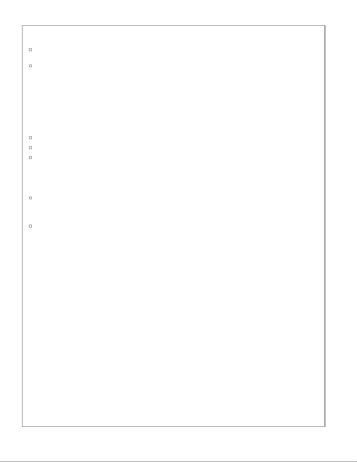
1. Install the Remote Dock
NOTE: The docking station comes with a 15’ (4.6 m) cord. Locate the docking station to allow the docking
cord to reach the toilet.
Unpack the box containing the remote control components.
Remove the remote control from the dock and set aside.
Remove the small screw on the bottom of the docking station.
Carefully remove the cover plate by gently prying the sides of the cover plate out until they
disconnect from the dock.
Carefully disconnect the cover plate plug.
Tape the screw to the cover plate and set it aside.
NOTE: When the docking station cord is routed externally through the wall, it may be easier to use the
back cord opening. When the cord is routed externally along the face of the wall, use the bottom cord
opening.
For installations using the back cord opening, route the power cord through the back cord opening.
For installations using the bottom cord opening, route the power cord through the bottom cord
opening.
Position the docking station in the installation position and mark the screw locations using the dock
as a template.
Drill appropriate size mounting holes at the screw mounting locations. The size of the hole will
depend on the need for wall anchors, wall material, and installation requirements.
Loosen each of the five small screws located where the wires will be connected.
Run the power cord into the docking station.
1132336-2-D 10 Kohler Co.
Page 11

Install the Remote Dock (cont.)
NOTE: There is a wiring schematic on the inside of the docking station. Refer to the schematic when
attaching the wires.
Slide the bare end of the wires into the correct port (as shown) and tighten each screw to secure the
wires in place.
Position the docking station over the installation location.
Connect the base plate of the docking station to the wall using two screws.
Reconnect the cover plate cable to the base.
Snap the cover plate back into place.
Remove the screw and tape from the cover plate and secure the cover plate with the screw to the
base of the docking station.
Kohler Co. 11 1132336-2-D
Page 12
For Wall Supply
Installations Only
Flange Centerlines
Screw Hole
Center the toilet
on the template.
Flange
For Throughthe-Floor
Supplies Only
Template
Tape
Top View
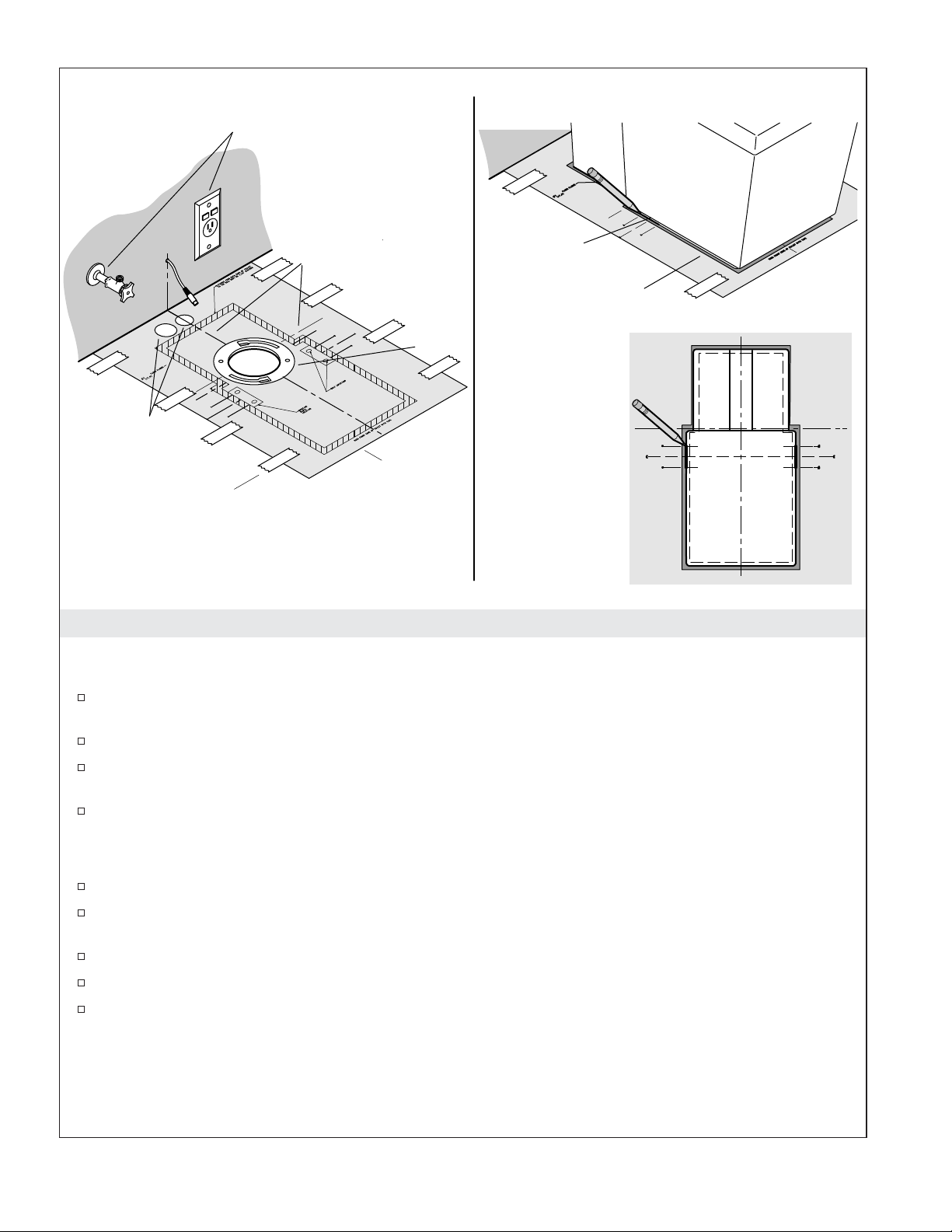
2. Prepare the Installation Location
IMPORTANT! Risk of product damage. If T-bolts are left in place, they will damage the toilet. Make sure
they are removed before moving the toilet into place.
If there are T-bolts extending from the flange, remove them. T-bolts are not required for this
installation.
Cut out the inside of the flange area on the template.
Position the template with the hole positioned over the flange. It is critical that the centerlines
marked on the template are centered on the flange.
Secure the template to the floor with tape.
IMPORTANT! Because of the unique design of this toilet, the width of the bottom edges of the toilet will
vary. The following steps are required because of this variation.
Confirm the template is correctly positioned and centered over the flange.
Position the toilet on the template. Make sure the front of the base of the toilet is aligned with the
markings on the template.
Position the toilet so an equal amount of shaded area is visible on each side of the template.
Confirm the toilet is centered by measuring the amount of space on each side of the template.
Directly under the screw holes on each side of the toilet, accurately mark the bottom edge of the
base. The mark should intersect the lines labeled ″C″ and ″A″ or ″B″ on each side of the template.
1132336-2-D 12 Kohler Co.
Page 13

A
C
B
B
C
A
A
Protective Material
Outside Edge
of Toilet
Top View
3. Determine Mounting Block Location
NOTE: There is a small amount of biodegradable, environmentally safe antifreeze added to the toilet tank
to prevent freezing during shipment. When the toilet is tipped forward, a small amount of the antifreeze
may run onto the floor. Make sure the floor is protected. Do not use a rug as protective material.
Position pieces of the box or other protective material on the floor directly in front of the toilet.
Gently tilt the toilet forward until it rests on the front surface.
A
NOTE: The installation range of the mounting block is marked on the template. Due to variances in the
width of the base, the exact location must be determined by the installer.
Measure the width of the base, dimension ″A,″ on the left side of the toilet.
From the mark indicating the outside edge of the base, measure inward and mark dimension ″A″ on
the template lines marked ″A.″
Draw a line connecting the marks on each of the lines labeled ″A.″
Measure the width of the base, dimension ″B,″ on the right side of the toilet.
From the mark indicating the outside edge of the base, measure inward and mark dimension ″B″ on
the template line marked ″B.″
Draw a line connecting the marks on each of the lines labeled ″B.″
IMPORTANT! Dimension ″C″ is the distance between the inside edges of the right and left base. The
distance between the outside edges of the mounting blocks should be slightly less than dimension ″C.″
The distance between the edge of the outside edge of the mounting block and the inside edge of the base
must be 1/16″ (2 mm) or less, or the strength of the mounting block will be compromised.
At the location of the screw holes in the side of the toilet, measure the width of the opening from
the inside edge of each side of the base, dimension ″C.″
Kohler Co. 13 1132336-2-D
Page 14

Determine Mounting Block Location (cont.)
Measure dimension ″C″ on the template, starting at the inside line.
Position a mounting block in the area indicated on the left side of the template. Align the outside
edge of the mounting blocks with the inside line.
Insert a pencil into each of the four pre-drilled holes in the mounting blocks and mark the center of
the holes.
Remove the mounting blocks.
At the four locations where the centerline in the slots marked on the template and the pencil mark
indicating the hole locations meet, drill a 3/16″ pilot hole or 1/2″ (13 mm) hole if anchors will be
used.
If anchors will be used, insert one of the supplied anchors in each of the holes.
Remove the template.
1132336-2-D 14 Kohler Co.
Page 15

For Wall Supply
Installations Only
Flanges
Clip
Hose Should Face
Down When Through
Floor
Supply
Hose
Lag Bolt
For Throughthe-Floor
Supplies Only
Wax
Ring
4. Install Mounting Blocks and Wax Ring
Position the mounting blocks over the mounting holes.
Secure each of the mounting blocks with two of the supplied lag bolts.
Position a wax ring on the flange.
Connect the Supply Hose to the Toilet
Slide the supply hose outlet into the toilet water inlet.
Slide the clip over the flanges on the supply hose and inlet. Make sure both flanges rest in the gap
in the clip and are firmly held in place.
CAUTION: Risk of property damage. It is critical that the supply hose be firmly secured by the
clip. The supply hose could be displaced when under pressure if the clip is not correctly installed,
resulting in water damage.
Confirm the clip is firmly holding the supply hose in place. The clip will be able to rotate freely
with no significant resistance when properly installed.
Kohler Co. 15 1132336-2-D
Page 16

External
Speaker
Connections
FM Antenna
Connection
Wall Supply
Installation
Shown
Docking
Station
Cord
Docking
Station
Cord
Bushing
Cap
Screw
5. Install the Toilet
Position the Toilet
Carefully lower the toilet into place, making sure the water supply line and electrical cord do not
interfere with the toilet when it is in place.
Connect the water supply hose to the supply stop.
Connect the docking station power cord.
Connect the optional external FM antenna (not shown) to the toilet if needed.
Connect the external speaker wires (not shown) to the toilet if external speakers are installed.
IMPORTANT! The remote control will not function when removed from the docking station until it has
charged for approximately 30 minutes. Flush the toilet manually or use the remote control while it is
attached to the docking station using the buttons on the toilet until the remote control is fully charged.
Place the remote control on the docking station.
Turn on the water supply.
Connect the power.
Check for Leaks
NOTE: Once the power is connected, the toilet will automatically enter start-up mode. This process takes
several minutes.
NOTE: If there is a failure during start-up mode, follow the directions on the remote control.
Once the start-up sequence has been completed flush the toilet using the manual buttons on the side
of the toilet.
1132336-2-D 16 Kohler Co.
Page 17
Install the Toilet (cont.)
Let the toilet fully refill and check for leaks.
Secure the Toilet
Insert the bushing into the screw hole in the side of the toilet.
Insert the supplied screws into the screw holes.
NOTE: A ratchet style screwdriver is the most effective tool when tightening the screws due to their close
proximity to the floor. It is difficult to achieve enough force with a standard screwdriver. There is a greater
risk of stripping the screws when a drill is used.
Thread each screw into the mounting blocks. Tighten the screws evenly to maintain the correct toilet
position.
Install the caps over the bushings.
Check the toilet to make sure it is level and does not rock.
Shim if necessary to level or eliminate rock.
Kohler Co. 17 1132336-2-D
Page 18
Cover
Slot
Spring
Clip
Docking
Station Cord
Docking Station
Cord
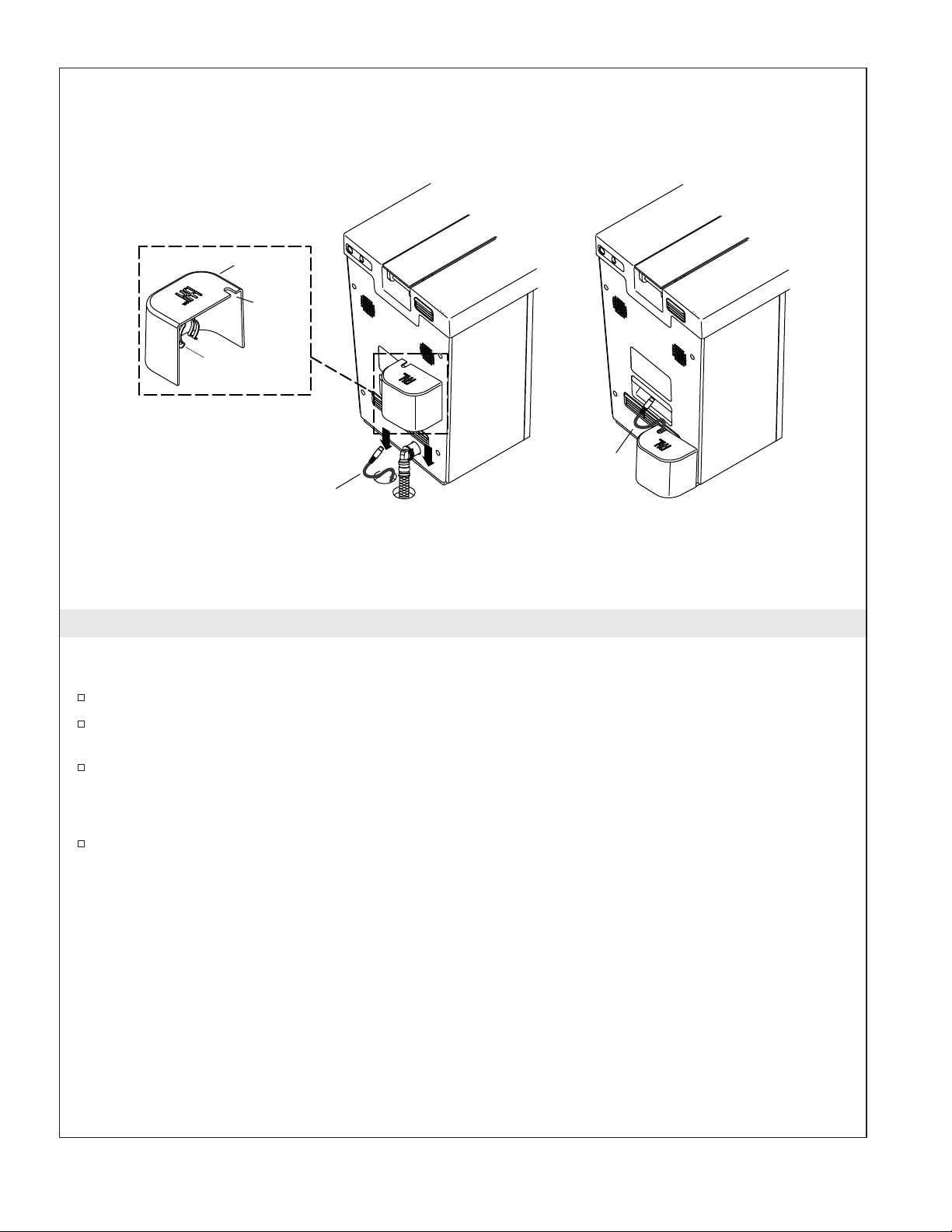
6. Install the Back Cover (Optional)
NOTE: Install the cover when the water and power supply are routed through the floor. The cover is not
designed for use when the water or electrical are connected to wall supplies.
Position the cover over the water supply and electrical supply holes.
Run the docking station cord through the slot in the cover and snap the cover into place on the
supply hose inlet.
Align the spring clip on the cover with the supply hose inlet.
NOTE: The clip will easily snap into place on the supply hose inlet. If there is significant resistance, make
sure the clip is not pushing the hose clip out of the way.
Lower the cover and snap the clip into place on the supply hose inlet.
1132336-2-D 18 Kohler Co.
Page 19

7. Remote Control Setup - Set the Language
NOTE: If the remote control has not charged enough to be removed from the docking station, perform
these steps with the remote control attached to the docking station.
NOTE: English is the default language. Skip this step if English is the desired language.
Changing the On-Screen Language
Select [settings].
Select [system settings].
Select [languages].
NOTE: If the language you desire does not appear on the screen, move the scroll bar down to see
additional language options.
Select the radio button for your desired language. The screen icons will immediately change.
Select [home] to return to the main screen or [back] to return to the previous screen.
Kohler Co. 19 1132336-2-D
Page 20

8. Remote Control Setup - Set the Date and Time
Set the Date
Select [settings].
Select [system settings].
Select [set date].
Use the UP and DOWN indicators to adjust the day, month, and year.
Select the desired radio button for the date format.
Select [home] to return to the main screen or [back] to return to the previous screen.
Set the Time
Select [settings].
Select [system settings].
Select [set time].
Select the radio button for the [12 hr.] or [24 hr.] option.
Use the UP and DOWN indicators to adjust the hour and minute.
Select the radio button for the [am] or [pm] option.
Select [home] to return to the main screen or [back] to return to the previous screen.
1132336-2-D 20 Kohler Co.
Page 21

9. Remote Control Setup - Connect the Remote Control
NOTE: This setting can be used to connect a new or a second remote control.
Select [settings].
Select [maintenance].
Select [learn remote].
Follow the instructions on the remote screen. When complete select [yes].
Kohler Co. 21 1132336-2-D
Page 22

10. Complete the Installation
Press the flush button on the remote control. Confirm the toilet flushes.
Remove the protective film from the toilet and remote.
Apply caulk around the base of the toilet following the caulk manufacturer’s instructions.
1132336-2-D 22 Kohler Co.
Page 23

Guide d’installation
W.C.
Informations importantes
REMARQUE: Ce produit est conçu pour l’installation avec les alimentations électriques et d’eau localisées
soit à travers le mur ou le sol.
Instructions de mise à la terre
•
Ce produit doit être mis à la terre. En cas de court-circuit, la mise à la terre réduit le risque
d’électrocution en apportant un câble d’échappement pour le courant électrique. Ce produit est
équipé d’un cordon muni d’un câble de mise à la terre avec une fiche de mise à la terre. Cette fiche
doit être branchée dans une prise correctement installée et mise à la terre.
AVERTISSEMENT: Risque d’électrocution. L’utilisation incorrecte de la fiche de mise à la terre
peut résulter en électrocution.
•
Si la réparation ou le remplacement de la corde ou de la fiche est nécessaire, ne pas brancher le
câble de mise à la terre au terminal à lame plate. Le câble avec isolation dont l’extérieur est vert
avec ou sans rayures jaunes est le câble de mise à la terre.
•
Vérifier auprès d’un électricien qualifié ou dépanneur en cas de doute par rapport aux instructions
de mise à la terre ou à la bonne mise à la terre du produit.
•
Ce produit est équipé en usine avec un cordon et une fiche électrique particuliers pour permettre le
branchement à un circuit électrique adéquat. S’assurer que le produit est connecté à une prise de
même configuration que celle de la fiche. Aucun adaptateur ne doit être utilisé avec ce produit. Ne
pas modifier la fiche fournie — si elle ne s’adapte pas à la prise, prévoir une prise adéquate installée
par un électricien qualifié. Si le produit doit être rebranché pour une utilisation sur un circuit
électrique différent, la connexion doit être réalisée par du personnel qualifié.
Outils et matériaux
Tournevis assortis
Perceuse avec
mèches assorties
Clé à molette
Plaque murale
Tournevis coudé
Plus:
• Matériel de protection
• Ruban
• Antibélier
Anneau de cire
Kohler Co. Français-1 1132336-2-D
Page 24

Contenu du sac de pièces
4 Tire-fonds de 5/16" x 2-1/2"
4 dispositifs d'ancrage de tire-fonds 5/16"
Station d'accueil
Télécommande
Avant de commencer
AVERTISSEMENT: Risque d’électrocution. Débrancher l’alimentation avant tout entretien.
2 blocs de fixation
Autres pièces
Couvercle arrière
(installations à travers
le plancher)
2 capuchons
2 vis #10 x 1-1/2"
Flexible
d'alimentation
2 bagues
Clip
AVERTISSEMENT: Risque d’électrocution. Pour des installations d’alimentation électrique à
montage mural: Raccorder uniquement à une prise mise à la terre de manière adéquate et protégée
par un disjoncteur de fuite de terre (GFCI) ou un appareil de courant résiduel (RCD) de 120 V, 15 A
minimum, 60 Hz. Ne pas retirer la cosse de masse ni utiliser d’adaptateur de mise à la terre.
ATTENTION: Risque de blessures. Ces W.C. pèsent environ 100 lb (45 kg). Lever les W.C. avec
deux personnes, en suivant une méthode de levage appropriée.
ATTENTION: Risque d’émanation de gaz nocifs. Si l’installation d’un nouveau W.C. n’est pas
immédiate, recouvrir temporairement la bride avec un chiffon.
ATTENTION: Risque d’endommagement du matériel. Ces W.C. ne sont pas destinés à être
installés dans des bâtiments dans lesquels les températures descendent au-dessous de 32°F (0°C). La
conception de ces W.C. rend l’extraction de l’eau qui se trouve dans le réservoir difficile. Si l’eau est
gelée, elle pourrait endommager le réservoir et créer une fuite.
AVIS: Respecter tous les codes de plomberie et électriques locaux.
IMPORTANT! Ce produit exige une pression statique minimum de 30 psi (206,8 kPa) pour assurer un
lavage satisfaisant du rebord.
Inspecter soigneusement les nouveaux WC contre tout défaut.
Consulter les guides en ligne sur le site kohler.com pour obtenir des informations supplémentaires.
Kohler Co. se réserve le droit d’apporter toute modification à la conception des produits et ce, sans
préavis, tel que spécifié dans le catalogue des prix.
Vérifier que toutes les pièces indiquées ci-dessous sont incluses avant de commencer l’installation.
1132336-2-D Français-2 Kohler Co.
Page 25

Avant de commencer (cont.)
Contenu du sac de pièces
(4) tire-fonds de 5/16″ x 2-1/2″
(4) dispositifs d’ancrage de tire-fonds de 5/16″
2 blocs de fixation
2 capuchons en plastique
2 vis #10 x 1-1/2″
2 bagues
Contenu du carton de la télécommande
Station d’accueil
Télécommande
Cordon d’alimentation de la station d’accueil (non illustré)
Antenne externe FM (non illustrée)
Cordon Audio AUX In (non illustré)
Autres pièces
Couvercle arrière (utilisé dans les installations à travers le plancher)
Tuyau d’alimentation
Collier
Kohler Co. Français-3 1132336-2-D
Page 26

29-1/2" (749 mm)
3-3/4" (95 mm),
3-9/16" (90 mm) Min
Avant de la cuvette
10-13/16" (275 mm)
4-3/4" (121 mm)
Alimentation
optionnelle,
filet de sortie
de
compression
1/2" diam. ext.
1-3/4"
(44 mm),
1-1/2"
(38 mm)
Min
36-1/4"
(921 mm)
12" (305 mm)
14-1/2"
(368 mm)
25-3/4"
(654 mm)
38" (965 mm) - 66" (1676 mm)
5-15/16"
(151 mm)
4-1/16"
(104 mm)
15-5/8"
(397 mm)
C
C
C
L de sortie
Alimentation
optionnelle filet de
sortie de compression
1/2" diam. ext.
Station d'accueil
2-1/4"
(57 mm)
41" (1041 mm) -
66" (1676 mm)
13-5/8"
(346 mm)
Filet de sortie de
compression
1/2" diam. ext.
6"
(152 mm)
Ø 2-5/8"
(67 mm)
8" (203 mm)
25-1/4"
(641 mm)
12"
(305 mm)
Le cordon
d'alimentation
atteint 56"
(1422 mm)
2" (51 mm)
Raccordement - Alimentation électrique et en eau à fixation murale
Mur fini
17-7/8"
(454 mm)
Sortie
AVERTISSEMENT: Risque d’électrocution. Débrancher l’alimentation avant tout entretien.
AVERTISSEMENT: Risque d’électrocution. Pour des installations d’alimentation électrique à
montage mural: Raccorder uniquement à un réceptacle mis à la terre de manière adéquate et
protégé par un disjoncteur de fuite de terre (GFCI) ou un appareil de courant résiduel (RCD). Ne
pas retirer la cosse de masse ni utiliser d’adaptateur de mise à la terre.
AVIS: Les emplacements pour l’arrêt d’alimentation, la prise électrique et le cordon de la station d’accueil
sont des emplacements suggérés. S’assurer que toutes les installations respectent les codes et normes
applicables.
IMPORTANT! Le panneau arrière sera difficile à retirer si le robinet d’arrêt d’alimentation se trouve
également à l’arrière des W.C. Il sera peut-être nécessaire de retirer les W.C. pour réaliser tout entretien
nécessaire sur les pièces qui se trouvent à l’arrière du panneau si le robinet d’alimentation dépasse le mur
de plus de 3″ (76 mm).
IMPORTANT! Ne rien installer à l’arrière des W.C. qui pourrait interférer avec le couvercle lorsque
celui-ci est relevé. La hauteur de tous les objets de décoration doit être d’au moins 37″ (940 mm), afin de
permettre un dégagement du couvercle.
La station d’accueil à distance est munie d’un cordon d’alimentation de 15’ (4,5 m). L’emplacement
de fixation de la station indiqué pour la station d’accueil est conforme aux normes ADA.
La longueur du cordon d’alimentation fourni est de 56″ (1422 mm). Installer la prise protégée par
GFCI ou RCD dans un rayon de 56″ (1422 mm) de l’emplacement des W.C.
Les W.C. sont munis d’un détecteur de mouvement qui permet l’ouverture automatique du
couvercle lors de la détection d’un mouvement. La plage maximale de ce détecteur est de 51-1/2″
(1300 mm). La sensibilité peut être réglée ou arrêtée en utilisant l’interface utilisateur.
1132336-2-D Français-4 Kohler Co.
Page 27

Raccordement - Alimentation électrique et en eau à fixation murale (cont.)
Les W.C. sont munis d’un détecteur pour ouvrir le siège automatiquement lors de l’interruption de
la lumière. Le détecteur se trouve sur le côté droit des W.C. La plage maximale de ce détecteur est
de 8″ (203 mm). Assurer que cette zone est dégagée de toutes obstructions.
Une prise de robinet d’arrêt d’alimentation de compression d’un diamètre extérieur de 1/2″ est
requise, sauf avec l’utilisation d’un adaptateur.
L’installation d’un antibélier est requise.
Kohler Co. Français-5 1132336-2-D
Page 28

Trou d'alimentation
électrique Ø 1-1/4"
(32 mm)
Trou d'alimentation
d'eau Ø 1-1/2"
(38 mm)
1-3/4"
(44 mm),
1-1/2"
(38 mm)
Min
36-1/4"
(921 mm)
29-1/2" (749 mm)
29 1/2" (74,9 cm)
3-3/4" (95 mm),
3-9/16" (90 mm) Min
14-1/2"
(368 mm)
25-3/4" (654 mm)
38" (965 mm) - 66" (1676 mm)
5-15/16"
(151 mm)
4-1/16"
(104 mm)
2-1/4"
(57 mm)
15-5/8"
(397 mm)
Station d'accueil
41" (1041 mm) -
66" (1676 mm)
Avant de la cuvette
10-13/16" (275 mm)
13-5/8"
(346 mm)
4-3/4" (121 mm)
Ø 2-5/8"
(67 mm)
25-1/4"
(641 mm)
12"
(305 mm)
Mur fini
17-7/8"
(454 mm)
12"
(305 mm)
C
L de sortie
Raccordement - Eau et composants électriques dans le plancher
AVIS: Les emplacements pour l’arrêt d’alimentation, la prise électrique et le cordon de la station d’accueil
sont des emplacements suggérés. S’assurer que toutes les installations respectent les codes et normes
applicables.
IMPORTANT! Ne rien installer à l’arrière des W.C. qui pourrait interférer avec le siège lorsque celui-ci est
relevé. La hauteur de tous les objets de décoration doit être d’au moins 37″ (940 mm), afin de permettre un
dégagement du siège.
La station d’accueil à distance est munie d’un cordon d’alimentation de 15’ (4,5 m). L’emplacement
de fixation de la station indiqué pour la station d’accueil est conforme aux normes ADA.
La longueur du cordon d’alimentation fourni est de 56″ (1422 mm).
Les W.C. sont munis d’un détecteur de mouvement qui permet l’ouverture automatique du
couvercle lors de la détection d’un mouvement. La plage maximale de ce détecteur est de 51-1/2″
(1300 mm). La sensibilité peut être réglée en utilisant l’interface utilisateur.
Les W.C. sont munis d’un détecteur actionneur de siège, situé sur le côté droit des W.C. La plage
maximale de ce détecteur est de 8″ (203 mm). Assurer que cette zone est dégagée de toutes
obstructions.
Une prise de robinet d’arrêt d’alimentation de compression d’un diamètre extérieur de 1/2″ est
requise, sauf avec l’utilisation d’un adaptateur.
L’installation d’un antibélier est requise.
1132336-2-D Français-6 Kohler Co.
Page 29

8" (203 mm)
2" (51 mm)
Disjoncteur
protégé-GFCI/
RCD
6"
(152 mm)
Cordon
d'alimentation
de la station
d'accueil
Arrêt
d'alimentation
3" (76 mm) Max.
lorsque situé à
l'arrière des W.C.
Préparer le site
2-5/8"
(67 mm)
Trou d'alimentation
d'eau Ø 1-1/2" (38 mm)
(
uniquement pour les installation
à travers le plancher
1-5/8"
(41 mm)
)
4"
(102 mm)
12" (305 mm)
recommandés à
partir du mur fini,
11-3/4" (298 mm) Min.
Trou d'alimentation électrique
Ø 1-1/4" (32 mm)
(uniquement pour les
installation à travers
le plancher)
Bride de sol
AVERTISSEMENT: Risque d’électrocution. Déconnecter l’alimentation électrique avant
l’installation ou l’entretien.
AVERTISSEMENT: Risque d’électrocution. Raccorder uniquement à une prise mise à la terre de
manière adéquate et protégée par un disjoncteur de fuite de terre (GFCI) ou un appareil de courant
résiduel (RCD) de 120 V, 15 A minimum, 60 Hz. Ne pas retirer la cosse de masse ni utiliser
d’adaptateur de mise à la terre.
AVERTISSEMENT: Risque d’électrocution. Pour des installations d’alimentation électrique à
travers le sol: Connecter uniquement à un circuit réservé, mis à la terre de manière adéquate et
protégé par un disjoncteur de fuite de terre (GFCI) ou un appareil de courant résiduel (RCD) de
classe A.
REMARQUE: La prise électrique et l’alimentation d’eau peuvent également être placées à l’arrière des
W.C. Si elles sont placées à l’arrière des W.C., le robinet d’arrêt d’alimentation d’eau ne doit pas dépasser
de plus de 3″ (76 mm) au-delà du mur fini. S’il est placé à l’arrière des W.C., le robinet d’arrêt
d’alimentation doit être un modèle qui se connecte à un angle de 90°. La poignée devrait pouvoir être
saisie sans difficulté.
REMARQUE: Le panneau arrière sera difficile à retirer si le robinet d’arrêt d’alimentation se trouve
également à l’arrière des W.C. Il sera peut-être nécessaire de retirer les W.C. pour réaliser tout entretien
nécessaire sur les pièces qui se trouvent à l’arrière du panneau si le robinet d’alimentation dépasse le mur
de plus de 3″ (76 mm).
Installer le cordon d’alimentation de la station d’accueil
Si le mur fini n’a pas été installé et si le cordon doit passer dans le mur, acheminer le cordon
d’alimentation de la station d’accueil dans le mur.
Kohler Co. Français-7 1132336-2-D
Page 30
Préparer le site (cont.)
Si le mur fini est installé, percer un trou de 3/8″ (10 mm) dans le mur à l’arrière de l’emplacement
des W.C. pour le cordon d’alimentation de la station d’accueil.
Si le cordon de la station d’accueil est acheminé à travers le mur, acheminer le cordon
d’alimentation vers l’emplacement de la station d’accueil à partir du côté des W.C. Acheminer le
cordon à travers une plaque murale ou acheminer celui-ci le long de l’extérieur du mur.
Installer l’alimentation d’eau
IMPORTANT! Lors de l’installation du tuyau d’alimentation, le raccorder d’abord aux W.C., puis au
robinet d’arrêt d’alimentation.
REMARQUE: La longueur du tuyau d’alimentation d’eau fourni est de 18″ (457 mm). Le tuyau fourni
doit être utilisé pour cette installation.
Installer l’alimentation d’eau et le robinet d’arrêt d’alimentation.
Installer un antibélier sur l’arrêt d’alimentation ou sur la conduite d’alimentation d’eau.
Vidanger la canalisation d’alimentation d’eau dans un seau ou un autre récipient pour éliminer tous
les débris.
Installer le service électrique
REMARQUE: La longueur du cordon d’alimentation fourni est de 56″ (1422 mm).
Placer une prise de mise à la terre réservée de 120 V, 15 A minimum, 60 Hz, protégée par un GFCI
ou RCD, dans un rayon de 56″ (1422 cm) de l’arrière des W.C.
Installer les fils des haut-parleurs externes (optionnel)
Si des haut-parleurs externes sont utilisés, installer les fils des haut-parleurs maintenant.
1132336-2-D Français-8 Kohler Co.
Page 31
Plaque
arrière
Plaque avant
Orifices
Ouverture
de cordon
arrière
Déconnecter.
Vis
Orange
Bleu
Rouge
Blanc
Cordon
de station
d'accueil
Noir
Faisceau de
connecteurs
Ouverture
de cordon
arrière
Ouverture de
cordon
inférieur
1. Installer la station d’accueil à distance
REMARQUE: La station d’accueil est fournie avec un cordon de 15’ (4,6 m). Placer la station d’accueil de
manière à permettre au cordon de celle-ci d’atteindre les W.C.
Déballer le carton comprenant les composants de la télécommande.
Retirer la télécommande de la station d’accueil et la mettre de côté.
Retirer la petite vis sur le fond de la station d’accueil.
Retirer avec précaution le couvercle en soulevant doucement les côtés du couvercle, jusqu’à ce qu’ils
soient déconnectés de la station d’accueil.
Déconnecter avec précaution la fiche du couvercle.
Attacher la vis sur le couvercle avec du ruban adhésif et mettre celui-ci de côté.
REMARQUE: Lorsque le cordon de la station d’accueil est acheminé à travers le mur au niveau externe, il
sera peut-être plus facile d’utiliser l’ouverture arrière du cordon. Lorsque le cordon est acheminé le long
de l’extérieur du mur, utiliser l’ouverture inférieure pour le cordon.
Pour les installations utilisant l’ouverture arrière pour le cordon d’alimentation, acheminer celui-ci à
travers l’ouverture arrière pour le cordon.
Pour les installations utilisant l’ouverture inférieure pour le cordon, acheminer le cordon
d’alimentation dans l’ouverture inférieure pour le cordon.
Mettre la station d’accueil en position d’installation et marquer les emplacements des vis en utilisant
la station d’accueil comme gabarit.
Percer des trous de fixation de la taille appropriée aux emplacements de fixation des vis. La taille du
trou dépend de la nécessité d’utiliser des dispositifs d’ancrage muraux, du matériau utilisé pour les
murs et des exigences d’installation.
Kohler Co. Français-9 1132336-2-D
Page 32

Installer la station d’accueil à distance (cont.)
Desserrer chacune des cinq petites vis situées à l’emplacement où les fils seront branchés.
Faire passer le cordon d’alimentation dans la station d’accueil.
REMARQUE: Un diagramme de câblage se trouve à l’intérieur de la station d’accueil. Se reporter au
diagramme lors de l’attache des fils.
Faire glisser l’extrémité à nu des fils dans le port adéquat (tel qu’illustré) et serrer chaque vis de
manière à fixer les fils en place.
Placer la station d’accueil sur l’emplacement d’installation.
Fixer la plaque du socle de la station d’accueil au mur en utilisant deux vis.
Rebrancher le câble du couvercle au socle.
Réenclencher le couvercle en place.
Retirer la vis et le ruban adhésif du couvercle et fixer le couvercle avec la vis sur le socle de la
station d’accueil.
1132336-2-D Français-10 Kohler Co.
Page 33

Pour installations à
alimentation murale seulement
Lignes centrales
de bride
Trou pour vis
Centrer les W.C.
sur le gabarit.
Bride
Pour
alimentations
à travers le
plancher
seulement
Gabarit
Mètre ruban
Vue de dessus
2. Préparer l’emplacement de l’installation
IMPORTANT! Risque d’endommagement du produit. Si les boulons en T restent en place, ils
endommageront les W.C. S’assurer qu’ils sont retirés avant de poser les W.C.
Si des boulons en T dépassent de la bride, les retirer. Cette installation ne nécessite pas de boulons
en T.
Couper l’intérieur de la zone de la bride sur le gabarit.
Positionner le gabarit avec le trou placé par-dessus la bride. Il est extrêmement important que les
lignes centrales indiquées sur le gabarit soient centrées sur la bride.
Fixer le gabarit sur le plancher avec du ruban adhésif.
IMPORTANT! Étant donné la conception unique de ces W.C., la largeur des bords du bas des W.C. varie.
Les étapes suivantes sont requises en raison de cette variation.
Confirmer que le gabarit est placé correctement et qu’il est centré par-dessus la bride.
Positionner les W.C. sur le gabarit. S’assurer que l’avant de la base des W.C. est aligné sur les
repères du gabarit.
Positionner les W.C. de manière à ce qu’une quantité égale de la zone grisée soit visible sur chaque
côté du gabarit.
Vérifier que les W.C. sont centrés en mesurant la quantité d’espace de chaque côté du gabarit.
Marquer le bord inférieur de la base de manière précise, directement sous les trous des vis de
chaque côté des W.C. Le repère doit intersecter les lignes marquées ″C″ et ″A″ ou ″B″ de chaque côté
du gabarit.
Kohler Co. Français-11 1132336-2-D
Page 34

A
C
B
B
C
A
A
Matériel de protection
Rebord
extérieur
des W.C.
Vue de dessus
3. Déterminer l’emplacement du bloc de fixation
REMARQUE: Une petite quantité d’antigel biodégradable, sans danger pour l’environnement, est ajoutée
au réservoir des W.C. pour empêcher une possibilité de gel pendant l’expédition. Lorsque les W.C. sont
basculés vers l’avant, une petite quantité d’antigel pourrait s’échapper sur le plancher. S’assurer que le
plancher est protégé. Ne pas utiliser de tapis comme matériel de protection.
Placer des morceaux du carton d’emballage ou tout autre matériel de protection sur le plancher,
directement devant les W.C.
Basculer doucement les W.C. vers l’avant, jusqu’à ce qu’ils reposent sur la surface avant.
A
REMARQUE: La plage d’installation du bloc de fixation est indiquée sur le gabarit. En raison des
variations de largeur de la base, l’emplacement exact doit être déterminé par l’installateur.
Mesurer la largeur de la base, soit la dimension ″A,″ sur le côté gauche des W.C.
À partir du repère indiquant le bord extérieur de la base, mesurer vers l’intérieur et marquer la
dimension ″A″ sur les lignes du gabarit marquées ″A.″
Tracer une ligne qui connecte les repères sur chacune des lignes dénommées ″A.″
Mesurer la largeur de la base, soit la dimension ″B,″ sur le côté droit des W.C.
À partir du repère indiquant le bord extérieur de la base, mesurer vers l’intérieur et marquer la
dimension ″B″ sur les lignes du gabarit marquées ″B″.
Tracer une ligne qui connecte les repères sur chacune des lignes ″B″.
IMPORTANT! La dimension ″C″ est la distance comprise entre les bords intérieurs de la base de droite et
de gauche. La distance entre les bords extérieurs des blocs de fixation doit être légèrement inférieure à la
dimension ″C″. La distance entre le bord du rebord extérieur du bloc de fixation et le bord intérieur de la
base doit être égale ou inférieure à 1/16″ (2 mm) afin de ne pas compromettre la solidité du bloc de
fixation.
1132336-2-D Français-12 Kohler Co.
Page 35

Déterminer l’emplacement du bloc de fixation (cont.)
À l’emplacement des trous de vis sur le côté des W.C., mesurer la largeur de l’ouverture à partir du
bord intérieur de chaque côté de la base, soit la dimension ″C.″
Mesurer la dimension ″C″ sur le gabarit, en commençant au niveau de la ligne intérieure.
Positionner un bloc de fixation dans la zone indiquée sur le côté gauche du gabarit. Aligner le bord
extérieur des blocs de fixation sur la ligne intérieure.
Insérer un crayon dans chacun des quatre trous percés au préalable dans les blocs de fixation et
marquer le centre des trous.
Retirer les blocs de fixation.
Au niveau des quatre emplacements où la ligne centrale dans les fentes marquées sur le gabarit et le
repère au crayon indiquant les emplacements des trous se rencontrent, percer un trou pilote de
3/16″ ou un trou de 1/2″ (13 mm) si des dispositifs d’ancrage sont utilisés.
Si des dispositifs d’ancrage sont utilisés, insérer l’un des dispositifs d’ancrage fourni dans chacun
des trous.
Retirer le gabarit.
Kohler Co. Français-13 1132336-2-D
Page 36

Pour installations à
alimentation murale
seulement.
Brides
Clip
Flexible
d'alimentation
Le tuyau doit être
tourné vers le bas
lorsqu'il passe par le
plancher
Tire-fond
Pour alimentations
à travers le plancher
seulement.
Anneau
de cire
4. Installer les blocs de fixation et l’anneau de cire
Placer les blocs de fixation par-dessus les orifices de fixation.
Fixer chaque bloc de fixation avec deux des tirefonds fournis.
Placer une bague de cire sur la bride.
Connecter le tuyau d’alimentation aux W.C.
Faire glisser la sortie du tuyau d’alimentation dans l’entrée d’eau des W.C.
Faire glisser le collier par-dessus les brides sur le tuyau d’alimentation et l’entrée. S’assurer que les
deux brides reposent dans l’écart du collier et qu’elles sont fermement maintenues en place.
ATTENTION: Risque d’endommagement du matériel. Il est important que le tuyau
d’alimentation soit bien fixé par le collier. Le tuyau d’alimentation pourrait se déplacer lorsqu’il est
sous pression si le collier n’est pas installé correctement, ce qui pourrait créer des dégâts d’eau.
Confirmer que le collier maintient fermement le tuyau d’alimentation en place. Le collier pourra
tourner librement sans résistance significative lorsqu’il est installé correctement.
1132336-2-D Français-14 Kohler Co.
Page 37

Connexions
externes de
haut-parleur
Connexion
d'antenne
FM
Installation à
alimentation
murale
illustrée
Cordon
de station
d'accueil
Cordon
de station
d'accueil
Manchon
Capuchon
Vis
5. Installer le W.C.
Positionner le W.C.
Abaisser les W.C. avec précaution pour les mettre en place, en s’assurant que la canalisation
d’alimentation d’eau et le cordon électrique n’interfèrent pas avec les W.C. lorsqu’ils sont en place.
Brancher le tuyau d’alimentation d’eau au robinet d’arrêt d’alimentation.
Brancher le cordon électrique de la station d’accueil.
Brancher l’antenne FM externe en option (non illustrée) aux W.C. si nécessaire.
Brancher les fils des haut-parleurs externes (non illustrés) aux W.C. si des haut-parleurs externes
sont installés.
IMPORTANT! La télécommande ne fonctionne pas lorsqu’elle est retirée de la station d’accueil, tant
qu’elle n’a pas été chargée pendant 30 minutes environ. Tirer la chasse d’eau manuellement ou utiliser la
télécommande lorsque celle-ci est sur la station d’accueil, en utilisant les boutons situés sur les W.C.,
jusqu’à ce que la télécommande soit entièrement chargée.
Placer la télécommande sur la station d’accueil.
Ouvrir l’alimentation d’eau.
Raccorder l’alimentation.
Vérifier s’il y a des fuites
REMARQUE: Lorsque l’alimentation est raccordée, les W.C. passent automatiquement en mode de
démarrage. Cette procédure peut prendre plusieurs minutes.
REMARQUE: En cas de défaillance pendant le mode de démarrage, suivre le mode d’emploi fourni sur la
télécommande.
Kohler Co. Français-15 1132336-2-D
Page 38

Installer le W.C. (cont.)
Lorsque la séquence de démarrage est terminée, passer la chasse d’eau en utilisant les boutons
manuels situés sur le côté des W.C.
Laisser les W.C. se remplir complètement et rechercher des fuites.
Fixer les W.C.
Insérer la bague dans le trou de vis situé sur le côté des W.C.
Insérer les vis fournies dans les orifices de vis.
REMARQUE: Un tournevis à cliquet est l’outil le plus efficace pour serrer les vis vu que celles-ci sont
tellement proches du plancher. Il est difficile d’obtenir assez de force avec un tournevis standard. Le risque
de dénuder les vis est plus grand avec l’utilisation d’une perceuse.
Visser chaque vis dans les blocs de fixation. Serrer les vis de manière égale afin de maintenir la
position correcte des W.C.
Installer les capuchons sur les bagues.
Inspecter les W.C. pour s’assurer qu’ils sont à niveau et qu’ils ne bougent pas.
Caler si nécessaire pour les mettre à niveau ou éliminer tout mouvement.
1132336-2-D Français-16 Kohler Co.
Page 39

Couvercle
Rainure
Clip à ressort
Cordon
de station
Cordon
de station
d'accueil
d'accueil
6. Installer le couvercle arrière (en option)
REMARQUE: Installer le couvercle lorsque l’alimentation d’eau et l’alimentation électrique sont
acheminées à travers le plancher. Le couvercle n’est pas destiné à être utilisé lorsque l’eau ou l’électricité
sont branchées à des alimentations murales.
Placer le couvercle sur les trous d’alimentation d’eau et d’alimentation électrique.
Acheminer le cordon de la station d’accueil dans la fente du couvercle et enclencher le couvercle sur
l’entrée du tuyau d’alimentation.
Aligner le clip à ressort sur le couvercle avec l’entrée du tuyau d’alimentation.
REMARQUE: Le clip s’enclenche sans difficulté sur l’entrée du tuyau d’alimentation. En cas de résistance
importante, vérifier que le clip ne pousse pas le collier du tuyau hors de sa position.
Abaisser le couvercle et enclencher le clip sur l’entrée du tuyau d’alimentation.
Kohler Co. Français-17 1132336-2-D
Page 40

7. Configuration de la télécommande - Définir la langue
REMARQUE: Si la télécommande n’a pas été chargée suffisamment pour être retirée de la station
d’accueil, suivre ces étapes avec la télécommande attachée sur la station d’accueil.
REMARQUE: La langue par défaut est l’anglais. Sauter cette étape si l’anglais est la langue souhaitée.
Modification de la langue à l’écran
Sélectionner [réglages].
Sélectionner [paramètres du système].
Sélectionner [langues].
REMARQUE: Si la langue souhaitée n’apparaît pas à l’écran, déplacer la barre de défilement vers le bas
pour voir les options de langues supplémentaires.
Sélectionner le bouton radio pour la langue souhaitée. Les icônes à l’écran changent immédiatement.
Sélectionner [accueil] pour retourner à l’écran principal ou [retour] pour retourner à l’écran
précédent.
1132336-2-D Français-18 Kohler Co.
Page 41

8. Configuration de la télécommande - Définir la date et l’heure
Régler la date
Sélectionner [réglages].
Sélectionner [paramètres du système].
Sélectionner [réglage de la date].
Utiliser les indicateurs vers le haut et vers le bas pour régler le jour, le mois et l’année.
Sélectionner le bouton radio souhaité pour le format de la date.
Sélectionner [accueil] pour retourner à l’écran principal ou [retour] pour retourner à l’écran
précédent.
Régler l’heure
Sélectionner [réglages].
Sélectionner [paramètres du système].
Sélectionner [réglage de l’horloge].
Sélectionner le bouton radio pour l’option [12 h] ou [24 h].
Utiliser les indicateurs vers le haut et vers le bas pour régler l’heure et les minutes.
Sélectionner le bouton radio pour l’option [am] ou [pm].
Sélectionner [accueil] pour retourner à l’écran principal ou [retour] pour retourner à l’écran
précédent.
Kohler Co. Français-19 1132336-2-D
Page 42

9. Configuration de la télécommande - Connecter la télécommande
REMARQUE: Ce réglage peut être utilisé pour connecter une nouvelle ou une deuxième télécommande.
Sélectionner [réglages].
Sélectionner [entretien].
Sélectionner [Util télécommande].
Suivre les instructions fournies sur l’écran distant. Lorsque la procédure est terminée, sélectionner
[oui].
1132336-2-D Français-20 Kohler Co.
Page 43

10. Terminer l’installation
Appuyer sur le bouton chasse d’eau sur la télécommande. Vérifier que la chasse des W.C.
fonctionne.
Retirer le film de protection des W.C. et de la télécommande.
Appliquer du mastic autour de la base des W.C. en suivant les instructions du fabricant du mastic.
Kohler Co. Français-21 1132336-2-D
Page 44
Guía de instalación
Inodoro
Información importante
NOTA: Este producto está diseñado para instalación con los suministros de agua y eléctricos a través de
la pared o del piso.
Instrucciones de conexión a tierra
•
Este producto se tiene que conectar a tierra. En caso de que haya un corto en el circuito eléctrico, la
conexión a tierra reduce el riesgo de descarga eléctrica proporcionando un alambre de escape para
la corriente eléctrica. Este producto está equipado con un cable que tiene un alambre de conexión a
tierra y un enchufe de conexión a tierra. El enchufe debe estar enchufado en un tomacorriente bien
instalado y conectado a tierra.
ADVERTENCIA: Riesgo de descarga eléctrica. El uso incorrecto del enchufe de conexión a tierra
puede ocasionar un riesgo de descarga eléctrica.
•
Si es necesario reparar o cambiar el cable o el enchufe, no conecte el alambre de conexión a tierra a
ninguno de los terminales de hoja plana. El alambre con aislamiento que tiene una superficie
exterior verde con o sin rayas amarillas es el alambre de conexión a tierra.
•
Si tiene alguna duda de si el producto está bien conectado a tierra, o si las instrucciones de conexión
a tierra no están completamente claras, solicite la verificación por un electricista calificado o
profesional de servicio.
•
Este producto viene equipado de fábrica con un cable específico y enchufe eléctrico que permite la
conexión a un circuito eléctrico adecuado. Asegúrese de que el producto se conecte a un
tomacorrientes que tenga la misma configuración que el enchufe. No utilice ningún tipo de
adaptador con este producto. No modifique el enchufe provisto — Si el enchufe no entra en el
tomacorrientes, pida a un electricista calificado que instale el tomacorrientes adecuado. Si el
producto se tiene que conectar para uso en un tipo diferente de circuito eléctrico, la conexión debe
realizarse por un personal de servicio calificado.
Herramientas y materiales
Destornilladores
Taladro con
brocas surtidas
Llave ajustable
surtidos
Placa mural
Destornillador
descentrado
Más:
• Material de protección
• Cinta adhesiva
• Amortiguador de golpe de
ariete
Anillo de cera
Kohler Co. Español-1 1132336-2-D
Page 45
4 Pernos de fijación de
5/16" x 2-1/2"
Contenido de la bolsa de piezas
2 Cubretornillos
2 Bujes
4 Anclajes para perno de
fijación de 5/16"
Estación de
conexión
Control remoto
Antes de comenzar
ADVERTENCIA: Riesgo de descarga eléctrica. Desconecte el suministro eléctrico antes de dar
servicio.
ADVERTENCIA: Riesgo de descarga eléctrica. Para instalaciones de enchufe/suministro eléctrico
a la pared: Enchufe sólo a un tomacorriente conectado a tierra apropiadamente, protegido por un
interruptor de circuito con pérdida a tierra (GFCI) o dispositivo de corriente residual (RCD) de 120
V, 15 A mínimo, 60 Hz. No quite la clavija de conexión a tierra del enchufe ni utilice un adaptador
para la conexión a tierra.
2 Bloques de montaje
Otras piezas
Cubierta posterior
(instalaciones a través
del nivel del piso)
2 Tornillos
del #10 x 1-1/2"
Manguera de
suministro
Clip
PRECAUCIÓN: Riesgo de lesiones personales. Este inodoro pesa aproximadamente 100 lbs (45
kg). Levante el inodoro con dos personas, que empleen la técnica adecuada para levantar.
PRECAUCIÓN: Riesgo de fuga de gases nocivos. Si el inodoro nuevo no se instala de inmediato,
cubra provisionalmente con un trapo la abertura de la brida del piso.
PRECAUCIÓN: Riesgo de daños a la propiedad. Este inodoro no está diseñado para su
instalación en edificios donde la temperatura baje a menos de 32°F (0°C). El diseño del inodoro
dificulta retirar toda el agua del tanque. Si se congela, el agua puede dañar el tanque ocasionando
fugas.
AVISO: Cumpla con todos los códigos locales de electricidad y de plomería.
¡IMPORTANTE! Este producto requiere una presión estática mínima de 30 psi (206,8 kPa) para un
funcionamiento satisfactorio de lavabo del borde.
Revise atentamente el nuevo inodoro para cerciorarse que no esté dañado.
Consulte la guía del usuario en línea en kohler.com para más información.
Kohler Co. Español-2 1132336-2-D
Page 46

Antes de comenzar (cont.)
Kohler Co. se reserva el derecho de modificar el diseño de productos sin previo aviso, tal como se
especifica en la lista de precios.
Verifique que todas las piezas que se indican a continuación estén incluidas antes de comenzar la instalación.
Contenido de la bolsa de piezas
(4) Pernos de fijación de 5/16″ x 2-1/2″
(4) Anclajes para perno de fijación de 5/16″
2 Bloques de montaje
2 Tapapernos de plástico
2 Tornillos del #10 x 1-1/2″
2 Bujes
Contenido de la caja del control remoto
Estación de conexión
Control remoto
Cable eléctrico de la estación de conexión (no se ilustra)
Antena externa FM (no se ilustra)
Cable audio de entrada AUX (no se ilustra)
Otras piezas
Cubierta posterior (se usa en instalaciones a través del piso)
Manguera de suministro
Clip
1132336-2-D Español-3 Kohler Co.
Page 47

29-1/2" (749 mm)
3-3/4" (95 mm),
3-9/16" (90 mm) Min
Frente de la taza
10-13/16" (275 mm)
4-3/4" (121 mm)
Suministro
opcional,
salida de
rosca de
compresión
de 1/2" D.E.
1-3/4"
(44 mm),
1-1/2"
(38 mm)
Min
36-1/4"
(921 mm)
25-3/4"
(654 mm)
38" (965 mm) - 66" (1676 mm)
5-15/16"
(151 mm)
4-1/16"
(104 mm)
12" (305 mm)
Línea central de la salida
14-1/2"
(368 mm)
Estación de
conexión
2-1/4"
(57 mm)
15-5/8"
(397 mm)
Suministro opcional,
salida de rosca
de compresión
de 1/2" D.E.
41" (1041 mm) -
66" (1676 mm)
13-5/8"
(346 mm)
Salida de rosca
de compresión
de 1/2" D.E.
6"
(152 mm)
Ø 2-5/8"
(67 mm)
12"
(305 mm)
8" (203 mm)
25-1/4"
(641 mm)
El cable
eléctrico alcanza
56" (1422 mm)
17-7/8"
(454 mm)
Tomacorriente
2" (51 mm)
Diagrama de instalación - Suministro de agua y eléctrico a la pared
Pared
acabada
ADVERTENCIA: Riesgo de descarga eléctrica. Desconecte el suministro eléctrico antes de dar
servicio.
ADVERTENCIA: Riesgo de descarga eléctrica. Para instalaciones de enchufe/suministro eléctrico
a la pared: Sólo enchufe a un tomacorriente conectado a tierra apropiadamente, protegido por un
interruptor de circuito con pérdida a tierra (GFCI) o dispositivo de corriente residual (RCD). No
quite la clavija de conexión a tierra del enchufe ni utilice un adaptador para la conexión a tierra.
AVISO: La ubicación de la llave de paso de suministro, el tomacorrientes, y el cable de la estación de
conexión son ubicaciones sugeridas. Asegúrese de que todas las instalaciones cumplan con los códigos y
normas aplicables.
¡IMPORTANTE! La ubicación de la llave de paso detrás del inodoro hará difícil retirar el panel posterior.
Puede ser necesario retirar el inodoro para reemplazar piezas detrás del panel posterior si la llave de paso
se extiende más de 3″ (76 mm) de la pared.
¡IMPORTANTE! No instale artículos detrás del inodoro que interfieran con la tapa cuando ésta se levante.
Todos los artículos decorativos deben estar a una altura de por lo menos 37″ (940 mm) para que haya
suficiente espacio para la tapa.
La estación de conexión remota está equipada con un cable eléctrico de 15’ (4,5 m). La ubicación de
montaje de la estación que se muestra para la estación de conexión cumple con la ADA.
El cable eléctrico provisto tiene una longitud de 56″ (1422 mm). Instale un tomacorrientes protegido
por un interruptor GFCI o RCD dentro de una distancia de 56″ (1422 mm) de la ubicación del
inodoro.
Kohler Co. Español-4 1132336-2-D
Page 48

Diagrama de instalación - Suministro de agua y eléctrico a la pared (cont.)
El inodoro está equipado con un sensor de movimiento para abrir la tapa automáticamente cuando
se detecta movimiento. El sensor tiene un rango máximo de 51-1/2″ (1300 mm). La sensibilidad se
puede ajustar o apagar utilizando la interface de usuario.
El inodoro está equipado con un sensor para abrir el asiento automáticamente cuando se interrumpe
la luz. El sensor está ubicado en el lado derecho del inodoro. Este sensor tiene un rango máximo de
8″ (203 mm). Mantenga esta área sin obstrucciones.
Se requiere una salida de llave de paso de compresión de 1/2″ D.E. a menos de que utilice un
adaptador.
Se requiere la instalación de un amortiguador de golpe de ariete.
1132336-2-D Español-5 Kohler Co.
Page 49

Orificio para fuente
de alimentación
eléctrica de Ø 1-1/4"
(32 mm)
Orificio para
suministro de agua
de Ø 1-1/2" (38 mm)
1-3/4"
(44 mm),
1-1/2"
(38 mm)
Min
36-1/4"
(921 mm)
29-1/2" (749 mm)
3-3/4" (95 mm),
3-9/16" (90 mm) mín
14-1/2"
(368 mm)
25-3/4" (654 mm)
38" (965 mm) - 66" (1676 mm)
5-15/16"
(151 mm)
4-1/16"
(104 mm)
2-1/4"
(57 mm)
15-5/8"
(397 mm)
Estación de
conexión
41" (1041 mm) 66" (1676 mm)
Frente de la taza
10-13/16" (275 mm)
13-5/8"
(346 mm)
4-3/4" (121 mm)
Ø 2-5/8"
(67 mm)
25-1/4"
(641 mm)
12"
(305 mm)
Pared acabada
17-7/8"
(454 mm)
12"
(305 mm)
Línea central de la salida
Diagrama de instalación - Suministros de agua y eléctrico a través del piso
AVISO: La ubicación de la llave de paso de suministro, el tomacorrientes, y el cable de la estación de
conexión son ubicaciones sugeridas. Asegúrese de que todas las instalaciones cumplan con los códigos y
normas aplicables.
¡IMPORTANTE! No instale artículos detrás del inodoro que interfieran al elevar el asiento. Todos los
artículos decorativos deben estar a una altura de por lo menos 37″ (940 mm) para dejar espacio para el
asiento.
La estación de conexión remota está equipada con un cable eléctrico de 15’ (4,5 m). La ubicación de
montaje de la estación que se muestra para la estación de conexión cumple con la ADA.
El cable eléctrico provisto tiene una longitud de 56″ (1422 mm).
El inodoro está equipado con un sensor de movimiento para abrir la tapa automáticamente cuando
se detecta movimiento. El sensor tiene un rango máximo de 51-1/2″ (1300 mm). La sensibilidad se
puede ajustar utilizando la interface de usuario.
El inodoro está equipado con un sensor accionador del asiento, ubicado en el lado derecho del
inodoro. Este sensor tiene un rango máximo de 8″ (203 mm). Mantenga esta área sin obstrucciones.
Se requiere una salida de llave de paso de compresión de 1/2″ D.E. a menos de que utilice un
adaptador.
Se requiere la instalación de un amortiguador de golpe de ariete.
Kohler Co. Español-6 1132336-2-D
Page 50

2" (51 mm)
Tomacorriente protegido
por un interruptor
GFCI/RCD
Cable eléctrico
de la estación
de conexión
Llave de paso
3" (76 mm) máx.
cuando se ubique
dentrás del inodoro
8" (203 mm)
2-5/8"
(67 mm)
Orificio para suministro
de agua de Ø 1-1/2" (38 mm)
(
sólo para instalaciones a través del piso
1-5/8"
(41 mm)
6"
(152 mm)
4"
(102 mm)
Se recomienda
12" (305 mm) de la
pared acabada,
11-3/4" (298 mm) mín
Orificio para la fuente de
alimentación eléctrica de
Ø 1-1/4" (32 mm) (sólo
para instalaciones a
través del piso)
Brida del piso
)
Prepare el sitio
ADVERTENCIA: Riesgo de descarga eléctrica. Desconecte el suministro eléctrico antes de instalar
o dar servicio.
ADVERTENCIA: Riesgo de descarga eléctrica. Enchufe sólo a un tomacorriente conectado a tierra
apropiadamente, protegido por un interruptor de circuito con pérdida a tierra (GFCI) o dispositivo
de corriente residual (RCD) de 120 V, 15 A mínimo, 60 Hz. No quite la clavija de conexión a tierra
del enchufe ni utilice un adaptador para la conexión a tierra.
ADVERTENCIA: Riesgo de descarga eléctrica. Para instalaciones de cableado directo/suministro
eléctrico a través del piso: Conecte sólo a un circuito dedicado con pérdida a tierra, protegido con
un interruptor de circuito (GFCI) Clase A o dispositivo de corriente residual (RCD).
NOTA: La salida eléctrica y el suministro de agua también se pueden ubicar detrás del inodoro. Si se
ubica detrás del inodoro, la llave de paso del suministro de agua debe sobresalir no más de 3″ (76 mm)
del material de la pared acabada. Si se ubica detrás del inodoro, la llave de paso debe ser de un modelo
que se conecte a un ángulo de 90°. La manija debe tener fácil acceso.
NOTA: La ubicación de la llave de paso detrás del inodoro hará difícil retirar el panel posterior. Puede ser
necesario retirar el inodoro para reemplazar piezas detrás del panel posterior si la llave de paso se
extiende más de 3″ (76 mm) de la pared.
Instale el cable eléctrico de la estación de conexión
Si la pared acabada no se ha instalado, tienda el cable eléctrico de la estación de conexión, si el
cable se instalará en la pared.
Si la pared acabada ya está instalada, taladre un orificio de 3/8″ (10 mm) en la pared que se
encuentra detrás del inodoro para el cable eléctrico de la estación de conexión.
1132336-2-D Español-7 Kohler Co.
Page 51

Prepare el sitio (cont.)
Si el cable de la estación de conexión se tiende en la pared, tienda el cable eléctrico a la estación de
conexión desde el extremo del inodoro. Tienda el cable a través de una placa mural o tienda el cable
externamente en la pared.
Instale el suministro de agua
¡IMPORTANTE! Al conectar la manguera de suministro, conéctela al inodoro primero, luego a la llave de
paso.
NOTA: La manguera de suministro de agua provista tiene una longitud de 18″ (457 mm). La manguera
provista se tiene que utilizar en esta instalación.
Instale el suministro de agua y la llave de paso.
Instale un amortiguador de golpe de ariete en la llave de paso o línea de suministro de agua.
Haga circular agua en la línea de suministro hacia una cubeta u otro recipiente para eliminar los
sedimentos y partículas.
Instale las conexiones eléctricas
NOTA: El cable eléctrico provisto tiene una longitud de 56″ (1422 mm).
Ubique un tomacorriente dedicado de 120 V, 15 A mínimo, 60 Hz con conexión a tierra y protegido
por un interruptor GFCI o RCD, dentro de una distancia de 56″ (1422 mm) de la parte posterior del
inodoro.
Instale los cables para bocinas externas (opcional)
Si se van a utilizar bocinas externas, instale los cables para bocina en este momento.
Kohler Co. Español-8 1132336-2-D
Page 52

Placa
posterior
Placa frontal
Orificios
Abertura
trasera
para cable
Desconecte.
Tornillo
Naranja
Azul
Rojo
Blanco
Abertura
trasera
para cable
Abertura
inferior para
cable
Cable de
la estación
de conexión
Negro
Arnés del
conector
1. Instale la estación remota
NOTA: La estación de conexión viene con un cable de 15’ (4,6 m). Ubique la estación de conexión de
manera que permita que el cable de la estación alcance el inodoro.
Desembale la caja que contiene los componentes del control remoto.
Retire el control remoto de la estación y colóquela a un lado.
Retire el tornillo pequeño del lado inferior de la estación de conexión.
Con cuidado retire la placa tapa apalancándola suavemente de los lados hacia fuera hasta que se
desconecte de la estación.
Con cuidado desconecte el enchufe de la placa tapa.
Con cinta adhesiva pegue el tornillo a la placa tapa y coloque a un lado.
NOTA: Cuando el cable de la estación de conexión se tiende externamente a través de la pared, puede ser
más fácil utilizar la abertura posterior para el cable. Cuando el cable se tienda externamente a lo largo de
la cara de la pared, utilice la abertura inferior para cable.
Para instalaciones que utilizan la abertura posterior para cable, tienda el cable eléctrico a través de
la abertura posterior para cable.
Para instalaciones que utilizan la abertura inferior para cable, tienda el cable eléctrico a través de la
abertura inferior para cable.
Coloque la estación de conexión en la posición de instalación y maque los lugares para tornillos
utilizando la estación como plantilla.
Taladre los orificios de fijación del tamaño adecuado en los lugares marcados para los orificios de
fijación. El tamaño del orificio dependerá de la necesidad de anclajes de pared, el material de la
pared y los requisitos de instalación.
1132336-2-D Español-9 Kohler Co.
Page 53

Instale la estación remota (cont.)
Afloje cada uno de los cinco tornillos pequeños ubicados donde se conectarán los cables.
Tienda el cable eléctrico hasta la estación de conexión.
NOTA: Hay un esquema de conexiones eléctricas en el interior de la estación de conexión. Consulte el
esquema al conectar los cables.
Deslice el extremo desnudo de los cables en el puerto correcto (como se muestra) y apriete cada
tornillo para fijar los cables en su lugar.
Coloque la estación de conexión sobre el lugar de la instalación.
Conecte la placa base de la estación de conexión a la pared utilizando dos tornillos.
Vuelva a conectar el cable de la placa tapa a la base.
Encaje la placa tapa nuevamente en su lugar.
Retire el tornillo y la cinta adhesiva de la placa tapa y fije la placa tapa con el tornillo a la base de la
estación de conexión.
Kohler Co. Español-10 1132336-2-D
Page 54

Sólo para instalaciones
con suministros de pared
Líneas centrales
de la brida
Orificio para
tornillo
Centre el inodoro
en la plantilla.
Brida
Sólo para
suministros a
través del piso
Plantilla
Cinta adhesiva
Vista superior
2. Prepare el lugar de instalación
¡IMPORTANTE! Riesgo de daños al producto. Si los pernos en T se dejan en el lugar, causarán daño al
inodoro. Asegúrese de retirarlos antes de mover el inodoro a su lugar.
Si hay pernos en T que sobresalgan de la brida, retírelos. Los pernos en T no son necesarios para
esta instalación.
Recorte el interior del área de la brida en la plantilla.
Coloque la plantilla con el orificio colocado sobre la brida. Es crítico que las líneas centrales
marcadas en la plantilla estén centradas en la brida.
Fije la plantilla al piso con cinta adhesiva.
¡IMPORTANTE! Debido al diseño único de este inodoro, el ancho de los filos inferiores del inodoro
puede variar. Los siguientes pasos son requisito debido a esta variación.
Verifique que la plantilla esté bien colocada y centrada sobre la brida.
Coloque el inodoro en la plantilla. Asegúrese de que el frente de la base del inodoro esté alineado
con las marcas en la plantilla.
Coloque el inodoro de manera que la misma cantidad del área sombreada sea visible en cada lado
de la plantilla.
Confirme que el inodoro esté centrado, midiendo la cantidad de espacio a cada lado de la plantilla.
Directamente debajo de los orificios para tornillo a cada lado del inodoro, marque con precisión el
filo inferior de la base. La marca debe intersectar las líneas identificadas ″C″ y ″A″ o ″B″ a cada lado
de la plantilla.
1132336-2-D Español-11 Kohler Co.
Page 55

A
C
B
B
C
A
A
Material de protección
Filo exterior
del inodoro
Vista superior
3. Determine la ubicación de los bloques de montaje
NOTA: El tanque del inodoro viene con una pequeña cantidad de anticongelante biodegradable que no
daña el medio ambiente para evitar el congelamiento durante el transporte. Cuando el inodoro se inclina
hacia delante, una pequeña cantidad del anticongelante puede correr al piso. Asegúrese de que el piso
tenga protección. No utilice un tapete como material de protección.
Coloque pedazos de la caja u otro material de protección sobre el piso directamente en frente del
inodoro.
Levante suavemente el inodoro hacia el frente hasta que descanse sobre la superficie delantera.
A
NOTA: El rango de instalación del bloque de montaje está marcado en la plantilla. Debido a variaciones
en el ancho de la base, el instalador debe determinar la ubicación exacta.
Mida el ancho de la base, dimensión ″A″, en el lado izquierdo del inodoro.
A partir de la marca que indica el filo exterior de la base, mida hacia dentro y marque la dimensión
″A″ en las líneas de la plantilla identificadas ″A″.
Trace una línea que conecte las marcas de cada línea identificada ″A″.
Mida el ancho de la base, dimensión ″B″, en el lado derecho del inodoro.
A partir de la marca que indica el filo exterior de la base, mida hacia dentro y marque la dimensión
″B″ en la línea de la plantilla identificada ″B″.
Trace una línea que conecte las marcas de cada línea identificada ″B″.
¡IMPORTANTE! La dimensión ″C″ es la distancia entre los filos internos de la base derecha e izquierda.
La distancia entre los filos exteriores de los bloques de montaje debe ser ligeramente menos que la
dimensión ″C″. La distancia entre el filo del filo exterior de los bloques de montaje y el filo interior de la
base debe ser de 1/16″ (2 mm) o menos, o se reducirá la resistencia del bloque de montaje.
Kohler Co. Español-12 1132336-2-D
Page 56

Determine la ubicación de los bloques de montaje (cont.)
En el lugar de los orificios para tornillo en el lado del inodoro, mida el ancho de la abertura desde
el filo interno de cada lado de la base, dimensión ″C″.
Mida la dimensión ″C″ en la plantilla, comenzando en la línea interna.
Coloque un bloque de montaje en el área indicada en el lado izquierdo de la plantilla. Alinee el filo
exterior de los bloques de montaje con la línea interior.
Inserte un lápiz en cada uno de los cuatro orificios previamente taladrados en los bloques de
montaje y marque el centro de los orificios.
Retire los bloques de montaje.
En los cuatro lugares donde se unen la línea central de las ranuras marcadas en la plantilla y la
marca de lápiz que indica los lugares de los orificios, taladre un orificio guía de 3/16″ o un orificio
de 1/2″ (13 cm) si va a utilizar anclajes.
Si va a utilizar anclajes, inserte uno de los anclajes provistos en cada orificio.
Retire la plantilla.
1132336-2-D Español-13 Kohler Co.
Page 57

Sólo para
suministros a
través del piso
Sólo para instalaciones
con suministros de pared
Perno de
fijación
Anillo
de cera
Bridas
Clip
La manguera debe
mirar hacia abajo
cuando el suministro
sea a través de piso
Manguera de
suministro
4. Instale los bloques de montaje y el anillo de cera
Coloque los bloques de montaje sobre los orificios de fijación.
Fije cada uno de los bloques de montaje con dos de los pernos de fijación provistos.
Coloque un anillo de cera en la brida.
Conecte la manguera de suministro al inodoro.
Deslice la salida de la manguera de suministro dentro de la entrada de agua del inodoro.
Deslice el clip sobre las bridas en la manguera de suministro y la entrada. Asegúrese de que ambas
bridas descansen en la separación en el clip y que estén sostenidas con firmeza en su lugar.
PRECAUCIÓN: Riesgo de daños a la propiedad. Es crítico que el clip asegure con firmeza la
manguera de suministro. La manguera de suministro se puede desplazar cuando esté bajo presión
si el clip no está bien instalado, ocasionando daños de agua.
Verifique que el clip sostenga con firmeza la manguera de suministro en su lugar. El clip podrá girar
libremente sin resistencia notable cuando esté bien instalado.
Kohler Co. Español-14 1132336-2-D
Page 58

Conexiones
de bocinas
externas
Conexión
de la
antena FM
Se muestra la
instalación con
suministros
de pared
Cable de la
estación de
conexión
Cable de la
estación de
conexión
Cubretornillo
Buje
Tornillo
5. Instale el inodoro
Coloque el inodoro
Con cuidado baje el inodoro a su lugar, asegurándose de que la línea de suministro de agua y el
cable eléctrico no interfieran con el inodoro cuando esté en su lugar.
Conecte la manguera de suministro de agua a la llave de paso.
Conecte el cable eléctrico de la estación de conexión.
Conecte la antena FM externa opcional (no se muestra) al inodoro si es necesario.
Conecte los cables de las bocinas externas (no se muestran) al inodoro si se van a instalar bocinas
externas.
¡IMPORTANTE! El control remoto no funcionará cuando se retira de la estación de conexión hasta que se
haya cargado por aproximadamente 30 minutos. Accione la descarga del inodoro manualmente o utilice el
control remoto estando conectado a la estación de conexión utilizando los botones en el inodoro hasta que
el control remoto esté completamente cargado.
Coloque el control remoto en la estación de conexión.
Abra el suministro de agua.
Conecte la alimentación eléctrica.
Verifique que no haya fugas
NOTA: Una vez que esté conectada la energía eléctrica, el inodoro automáticamente entrará al modo de
encendido. Este proceso puede llevarse varios minutos.
NOTA: Si ocurre una falla durante el modo de encendido, siga las instrucciones en el control remoto.
1132336-2-D Español-15 Kohler Co.
Page 59

Instale el inodoro (cont.)
Una vez que la secuencia de encendido haya terminado, accione la descarga del inodoro utilizando
los botones manuales en el lado del inodoro.
Deje que el inodoro se vuelva a llenar y verifique no haya fugas.
Fije el inodoro
Inserte el buje en el orificio para tornillo en el lado del inodoro.
Instale los tornillos provistos en los orificios para tornillo.
NOTA: Un destornillador tipo trinquete es la herramienta más efectiva para apretar los tornillos debido a
la proximidad al piso. Es difícil lograr suficiente fuerza con un destornillador estándar. Hay un mayor
riesgo de dañar las roscas de los tornillos cuando se utiliza un taladro.
Enrosque cada tornillo en los bloques de montaje. Apriete el tornillo uniformemente para mantener
la posición correcta del inodoro.
Instale las tapas en los bujes.
Verifique que el inodoro esté a nivel y que no se columpie.
Utilice cuñas si es necesario para nivelar o eliminar el columpiado.
Kohler Co. Español-16 1132336-2-D
Page 60

Cubierta
Ranura
Clip de resorte
Cable de la
estación de
Cable de la
estación de
conexión
conexión
6. Instale la cubierta posterior (opcional)
NOTA: Instale la cubierta cuando se pasen el suministro de agua y la alimentación eléctrica a través del
piso. La cubierta no está diseñada para utilizarla cuando el agua y la alimentación eléctrica están
conectadas a la pared.
Coloque la cubierta sobre los orificios para el suministro de agua y la alimentación eléctrica.
Tienda el cable de la estación de conexión a través de la ranura en la cubierta, y encaje la cubierta
en su lugar en la entrada de la manguera de suministro.
Alinee el clip de resorte en la cubierta con la entrada de la manguera de suministro.
NOTA: El clip encajará fácilmente en su lugar en la entrada de la manguera de suministro. Si existe
notable resistencia, asegúrese de que el clip no esté empujando el clip de la manguera hacia fuera.
Baje la cubierta y encaje el clip en su lugar en la entrada de la manguera de suministro.
1132336-2-D Español-17 Kohler Co.
Page 61

7. Configuración del control remoto - Establezca el idioma
NOTA: Si el control remoto no se ha cargado lo suficiente para retirarlo de la estación de conexión,
ejecute estos pasos con el control remoto conectado a la estación de conexión.
NOTA: El inglés es el idioma predeterminado. Sáltese este paso si el inglés es el idioma deseado.
Cómo cambiar el idioma de la pantalla
Seleccione [configuración].
Seleccione [configuraciones del sistema].
Seleccione [idiomas].
NOTA: Si el idioma que usted desea no aparece en la pantalla, mueva hacia abajo la barra de
desplazamiento para ver opciones de idiomas adicionales.
Seleccione el botón de radio de su idioma preferido. Los iconos de la pantalla cambiarán
inmediatamente.
Seleccione [inicio] para regresar a la pantalla principal o [atrás] para regresar a la pantalla anterior.
Kohler Co. Español-18 1132336-2-D
Page 62

8. Configuración del control remoto - Establezca la fecha y la hora
Establezca la fecha
Seleccione [configuración].
Seleccione [configuraciones del sistema].
Seleccione [establecer fecha].
Utilice los indicadores hacia ARRIBA o hacia ABAJO para ajustar el día, el mes y el año.
Seleccione el botón de radio deseado para el formato de fecha.
Seleccione [inicio] para regresar a la pantalla principal o [atrás] para regresar a la pantalla anterior.
Establezca la hora
Seleccione [configuración].
Seleccione [configuraciones del sistema].
Seleccione [establecer hora].
Seleccione el botón de radio para la opción de [12 hr.] o [24 hr.].
Utilice los indicadores hacia ARRIBA o hacia ABAJO para ajustar la hora y los minutos.
Seleccione el botón de radio para la opción de [am] o [pm].
Seleccione [inicio] para regresar a la pantalla principal o [atrás] para regresar a la pantalla anterior.
1132336-2-D Español-19 Kohler Co.
Page 63

9. Configuración del control remoto - Conecte el control remoto
NOTA: Esta configuración se puede utilizar para conectar un control remoto nuevo o un segundo control
remoto.
Seleccione [configuración].
Seleccione [mantenimiento].
Seleccione [uso del control remoto].
Siga las instrucciones en la pantalla del control remoto. Al terminar seleccione [sí].
Kohler Co. Español-20 1132336-2-D
Page 64

10. Termine la instalación
Oprima el botón de descarga en el control remoto. Verifique que se accione la descarga del inodoro.
Retire la película protectora del inodoro y del control remoto.
Aplique sellador al rededor de la base del inodoro siguiendo las instrucciones del fabricante del
sellador.
1132336-2-D Español-21 Kohler Co.
Page 65

1132336-2-D
Page 66

1132336-2-D
Page 67

1132336-2-D
Page 68

USA/Canada: 1-800-4-KOHLER
México: 001-877-680-1310
kohler.com
©2012 Kohler Co.
1132336-2-D
 Loading...