

Kohler K161374APB Installation Manual
BEFORE YOU BEGIN
HOW TO USE THESE INSTRUCTIONS
VACUUM BREAKER
Please read these instructions carefully to familiarize
yourself with the required tools, materials, and installation
sequences. Follow the sections that pertain to your
particular installation. This will aid you in avoiding the
unnecessary expense associated with improper
installation. In addition to proper installation, read all
operating and safety instructions.
NOTES
Review all local plumbing and building codes.
Bottom of vacuum breaker must be positioned at
least 6” above fixture rim. Local codes may differ.
Piping should run downward, regardless of rough-in
height.
**Variation and/or finish/color code may be required
when ordering.
CAUTION: Risk of product damage. Do not
subject vacuum breaker to continuous pressure for
more than 12 hours.
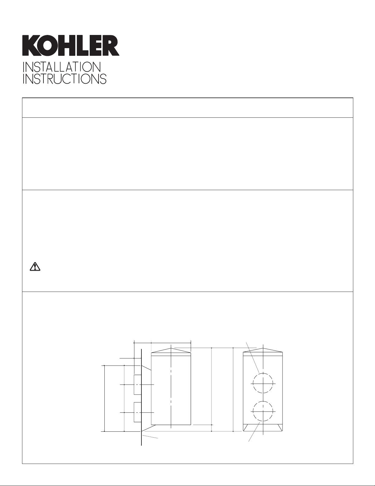
ROUGHING-IN
Rough-in inlet and outlet piping using Fig. #1.
All information in these instructions is based on the latest
product information available at the time of publication.
Kohler Co. reserves the right to make changes in product
characteristics, packaging, or availability at any time
without notice.
TOOLS AND MA TERIALS REQUIRED
Seat wrench (Kohler #21261) or 7/16” square bar
Hex head wrench, 5/32”
Thread sealant
NOTE: Locate outlet piping at the top and inlet piping at
the bottom.
7/8”
3/8”
1”
3-3/8”
105833-2-AA (A)
1-3/8”
1”
FINISHED
WALL
2” D.
1/2” I.P.S. OUTLET
3-7/8”
4-1/4”
3/8”
1/2” I.P.S. INLET
Fig. #1
Copyright 1998 Kohler Co.
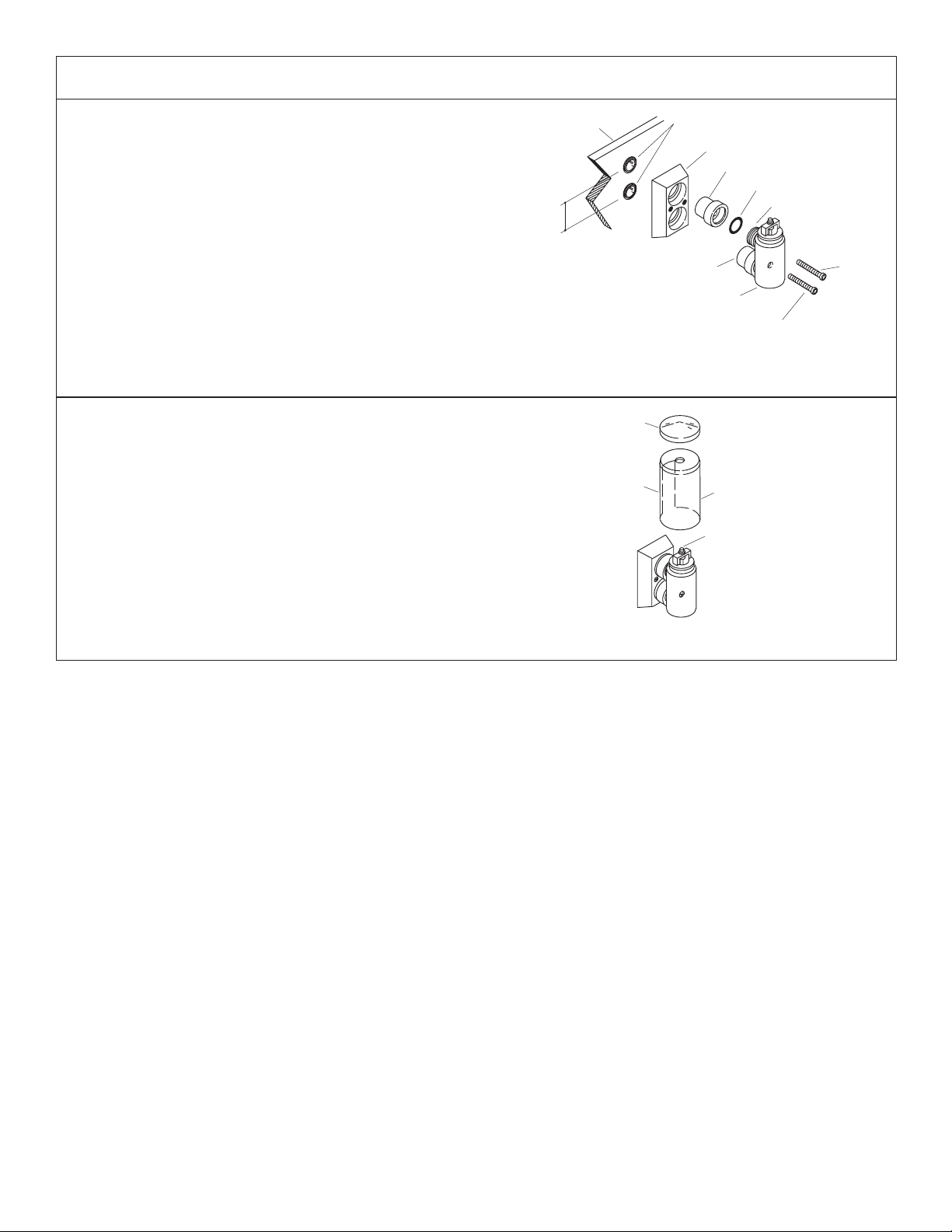
INSTALLATION
Install two 1/2” I.P.S. nipples on inlet and outlet piping to
extend to outside edge of finished wall.
Place wall bracket over nipples. Insert sleeves into wall
bracket and thread onto nipples. Tighten sleeves using
seat wrench or 7/16” square bar.
Install an O-ring on vacuum breaker inlet and outlet ports.
Lubricate O-rings to ease assembly.
Slide vacuum breaker inlet/output ports into sleeves in
wall bracket and secure with two socket head screws. Use
5/32” hex head wrench.
NOTE: Do not install shroud until all construction and
rough installation is complete.
Place shroud over vacuum breaker with cut-out over
input/output ports and threaded pin through hole at top of
shroud.
Thread cover onto threaded pin until hand-tight.
Finished
Wall
1-3/8”
1/2” I.P.S. Nipples
Inlet Port
Vacuum Breaker
Body
Fig. #2
Cover
Slot
Wall Bracket
Sleeve
O-Ring
Outlet Port
Socket
Head
Screw
Socket Head
Screw
Shroud
Threaded Pin
Fig. #3
105833-2-
AA (A)
2
Kohler Co., Kohler, WI
 Loading...