

Kohler K-1122-XHGLA-7 Installation And Care Manual

Installation and Care Guide
Whirlpool Bath with Airjets
Standard Installation
Retain serial number for reference.
Conserver le numéro de série pour référence.
Guarde el número de serie para referencia:____________
Français, page “Français-1”
Español, página “Español-1”
1208027-2-F
Installation Instructions
WARNING: When using electrical products, basic precautions should always be followed,
including the following:
DANGER: Risk of electric shock. Connect only to a circuit protected by a Ground-Fault
Circuit-Interrupter (GFCI)*.
Building materials and wiring should be routed away from the whirlpool pump, blower motor, and other
heat-producing components of the unit.
Install to permit access for servicing.
A pressure wire connector marked ″Earth/Ground″ is provided within the wiring compartment. To reduce
the risk of electric shock, connect this connector to the grounding terminal of your electric service or supply
panel with copper wire equivalent in size to the circuit conductor supplying this equipment.
A pressure wire connector is provided on the exterior of the pump or control within this unit to permit
connection of a bonding conductor between this unit and all the other exposed metal in the vicinity, as
needed to comply with local requirements.
Grounding is required. The unit should be installed by a qualified service representative, and grounded.
WARNING: Risk of injury or property damage. Please read all instructions thoroughly before
beginning installation, including the following requirements.
WARNING: Risk of electric shock. A qualified electrician should make all electrical connections.
WARNING: Risk of electric shock. Disconnect power before servicing.
NOTICE: Follow all local plumbing and electrical codes. In Canada, install this unit in accordance with
the Canadian Electrical Code, Part 1.
*Outside North America, this device may be known as a Residual Current Device (RCD).
Product Information
Electrical Requirements
The installation must have Class A Ground-Fault Circuit-Interrupters (GFCI’s). The GFCI’s protect against
line-to-ground shock hazards. Use 120 V, 15 A, 60 Hz dedicated services for the pump motor and blower.
″H″ models require a separate 120 V, 15 A, 60 Hz dedicated service for the heater.
If a power supply cord is damaged, it must be replaced by the manufacturer, its service agent or similarly
qualified persons in order to avoid a hazard. The heater supply cord cannot be replaced. If the heater supply
cord is damaged the heater must be replaced.
Product Notices
WARNING: Unauthorized modification may cause unsafe operation and poor performance of
the bath. Do not relocate the whirlpool pump motor or blower motor, or make other modifications
to the bath system, as this could adversely affect the performance and safe operation of the product.
Kohler Co. shall not be liable under its warranty or otherwise for personal injury or damage caused
by any such unauthorized modification.
NOTICE: Keep the area around the blower clean and free of debris. Ensure that the area around the
blower is free of sawdust, insulation, dirt, and other small loose debris. Such material can block the blower
air ducts and reduce the air flow through the blower.
NOTICE: This product contains an automatic water purge mode that turns the blower on for 2 minutes
about 30 minutes after the unit is turned off and drained.
1208027-2-F 2 Kohler Co.
Product Information (cont.)
Features
Factory-installed components include a pump motor, heater (H models), and blower motor (each with a
separate power supply cord), whirlpool jets, air piping, air switch, and user keypad. Other than electrical
wiring and plumbing, no assembly is needed.
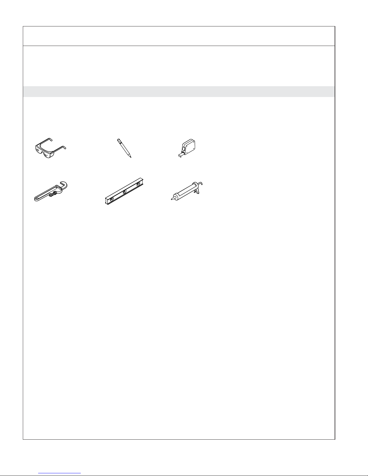
Tools and Materials
Plus:
• Conventional Woodworking
Tools and Materials
• Drop Cloth
• Construction Adhesive (Optional)
• Cement* or Mortar (Optional)
• 2x4s
* Do not use gypsum cement.
100% Silicone Sealant
Kohler Co. 3 1208027-2-F
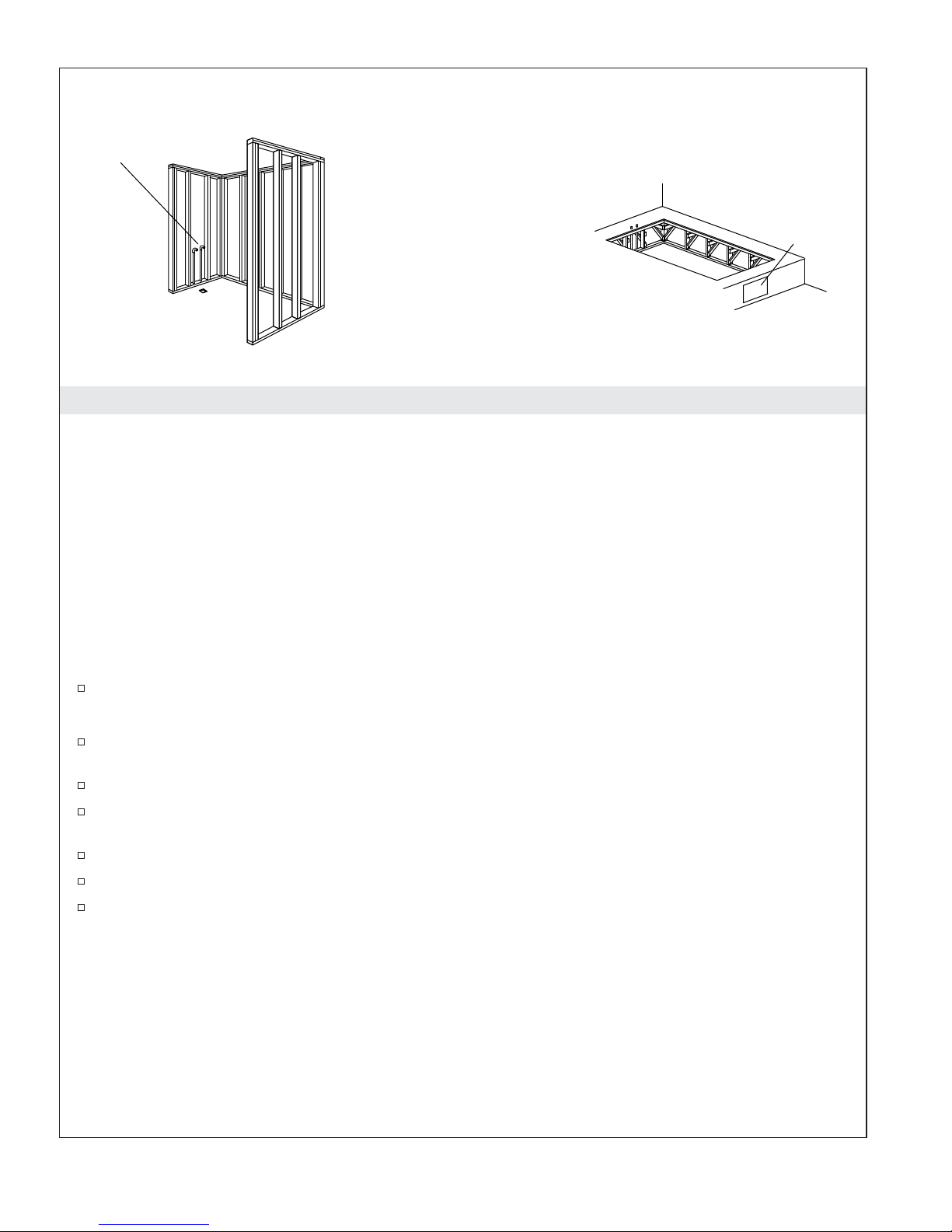
Alcove Drop-In
Position the
rough plumbing.
Construct 2x4
stud framing
according to the
Position the
rough plumbing.
product dimensions.
Construct according
to the product dimensions.
Access
Panel
Verify that the subfloor
offers adequate support,
and is flat and level.
Verify that the subfloor
offers adequate support,
and is flat and level.
1. Prepare the Site
NOTICE: Measure your actual product for site preparation. Note the model number located on the
pump/blower end of the bath, then visit the product page at www.kohler.com for more information.
NOTICE: Drop-in models are not intended for alcove installation. Use a flanged model for alcove areas.
NOTICE: Provide adequate ventilation and a minimum 15 cubic feet (.4 cubic meters) of air space in the
installed location for cooling the motor and to supply sufficient air for the blower. Do not install the
blower motor closer than 1″ (25 mm) from the wall or other objects.
NOTICE: Provide generous, unrestricted access to the pump and blower. You must provide access
immediately next to the pump, blower, and controls for servicing.
NOTICE: Do not support the weight of the bath by the rim.
NOTE: Drop-in or alcove installation is possible, depending on the product chosen.
Carefully unpack and inspect the new bath for damage before installation. If there is damage do not
install the bath; contact your dealer.
Make sure the flooring offers adequate support for your bath, and verify that the subfloor is flat and
level.
Construct 2x4 stud framing.
Install an access panel on the pump/blower end of the bath for servicing. The access panel must be
at least 30″ (762 mm) wide by 15″ (381 mm) high.
Install the rough plumbing.
Install the drain to the bath according to the drain manufacturer’s instructions.
Protect the bath surface by positioning a clean drop cloth in the basin bottom.
1208027-2-F 4 Kohler Co.
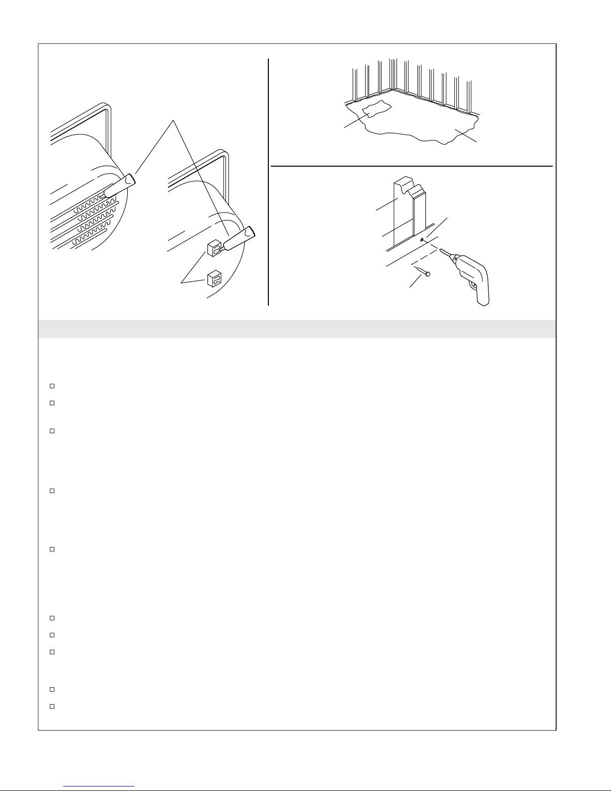
Option 1
Apply construction
adhesive.
Option 2
Clear a space
for the pump
and blower.
Alcove Installations
Stud
Furring
Strip
Cement or
Mortar Bed
Drill a small hole
through the nailing-in
flange at each stud.
Support Blocks
Nail
2. Install the Bath
NOTICE: Do not lift the bath by the piping or blower, or use the piping or blower for structural support
of the bath. To avoid damage to the bath, lift by the rim at the sides of the bath.
If the subfloor is not level, shim the bath support blocks as necessary.
Option 1: Construction adhesive: Apply a generous amount of high-quality construction adhesive
to the bottom of the support blocks or molded supports.
Option 2: Cement or mortar bed: Apply 1″ (25 mm) to 2″ (51 mm) of mortar cement in the
installation area. Do not use gypsum cement or drywall compound, as they will not provide an
acceptable, durable bond.
IMPORTANT! Use care not to pinch or crush the flexible tubing as the bath is placed into position.
With help, carefully lift the bath into position. Shift the flexible tubing away from any pinch points.
Cut the Pump Banding Straps
IMPORTANT! Perform this step to make the whirlpool operate more quietly.
Cut the two pump banding straps from the whirlpool pump.
NOTE: Do not raise the pump higher than it was before you cut the straps. If the pump is raised too
high, it will not prime properly. Make sure the rubber isolation feet are in place.
Drop-In Installation
Install the drain tee and tailpiece. Secure the tailpiece into the trap.
Install the faucet valve.
Check the drain connections for leakage.
Alcove Installation
Drill a small pilot hole through the nailing-in flange at each stud. Add shims as needed.
Use large-head galvanized nails to secure the nailing-in flange to the studs.
Kohler Co. 5 1208027-2-F

Install the Bath (cont.)
Nail 1/4″ (6 mm) thick furring strips to the studs.
Insert the drain tailpiece into the trap. Secure the drain tailpiece to the trap.
Install the faucet valve.
Check the drain connections for leakage.
1208027-2-F 6 Kohler Co.
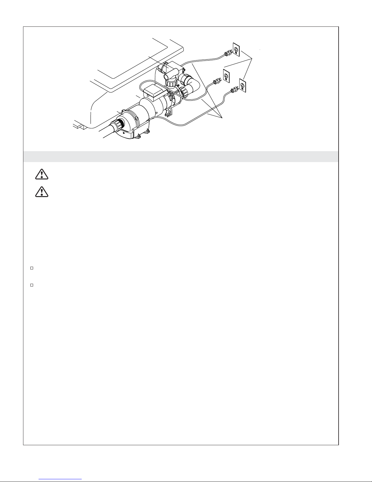
Bond in accordance with
applicable codes.
Heater
Pump
Blower
24" (610 mm) Maximum
Cord Length
3. Make the Electrical Connections – USA and Mexico
WARNING: Risk of electric shock. Make sure the power has been disconnected before performing
the following procedures.
WARNING: Risk of electric shock. Connect the pump motor, in-line heater (if included), and
blower to properly grounded, grounding-type receptacles protected by Ground-Fault
Circuit-Interrupters (GFCI’s) or Residual Current Devices (RCD’s). Do not remove the grounding
pins from the plugs. Do not use grounding adapters.
GFCI-Protected
120 V, 15 A
Grounded Outlet
NOTICE: The pump motor, in-line heater (if included), and blower are equipped with cords and plugs. A
qualified electrician must install a dedicated GFCI- or RCD-protected, 120 V, 15 A, grounded outlet for
each device. No other load should be on these circuits.
NOTE: A label identifying the model number and electrical rating of the product is located near the
whirlpool pump.
Install electrical outlets behind the bath, at least 1-1/2″ (38 mm) above the subfloor, and within
reach of the 24″ (610 mm) power cords.
Plug the pump motor, blower, and in-line heater (if included) into these outlets.
NOTE: Make sure the air actuator tubing is securely attached to the pump, and is not kinked or
damaged.
Kohler Co. 7 1208027-2-F
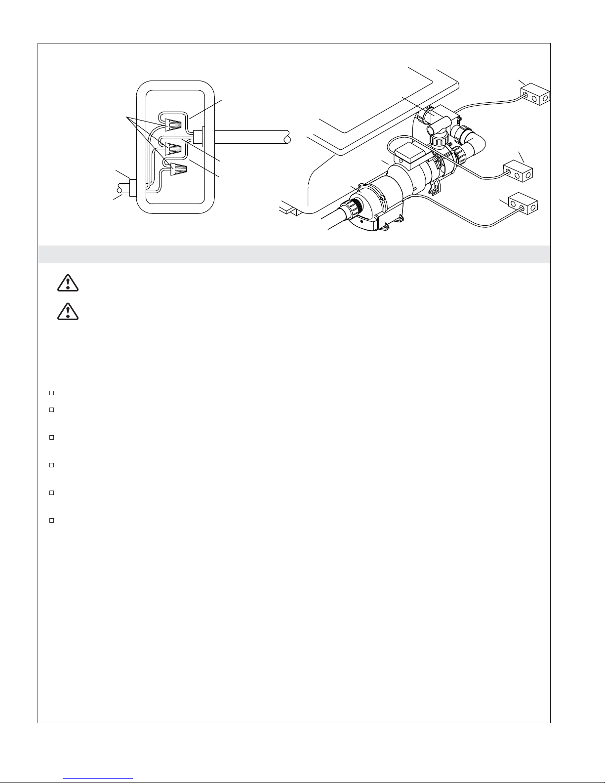
Typical Field Wiring Connection
For Each Device
Bond in accordance with
applicable codes.
Junction Box
Heater
Pump
Junction
Box
Wire Connectors
Provide suitable
strain relief.
Supply from
Branch
Circuit Box
Ground
Line (Black)
Neutral (White)
Blower
4. Make the Electrical Connections – Canada
WARNING: Risk of electric shock. Make sure the power has been disconnected before performing
the following procedures.
WARNING: Risk of electric shock. Connect the pump motor, in-line heater (if included), and
blower to a properly grounded, grounding-type Ground-Fault Circuit-Interrupter (GFCI) or
Residual Current Device (RCD). This will provide additional protection against line-to-ground
shock hazard.
NOTE: A label identifying the model number and electrical rating of the whirlpool is located near the
whirlpool pump.
Junction
Box
Locate and secure each supplied junction box a minimum of 1-1/2″ (38 mm) above the subfloor.
The whirlpool controls and system have been prewired at the factory. A qualified electrician should
make a routine service connection to the junction box.
Connect service to the junction box. The 60 Hz model junction box contains line (black) and neutral
(white) wires and a ground lug.
A 120 V, 15 A dedicated circuit is required for each device. Provide a Class A GFCI or RCD for each
dedicated circuit.
Provide a separate equipment grounding conductor for the inside ground or ground lug. The
conductor must not be connected to any current-carrying conductor.
Bond in accordance with national and local codes.
1208027-2-F 8 Kohler Co.
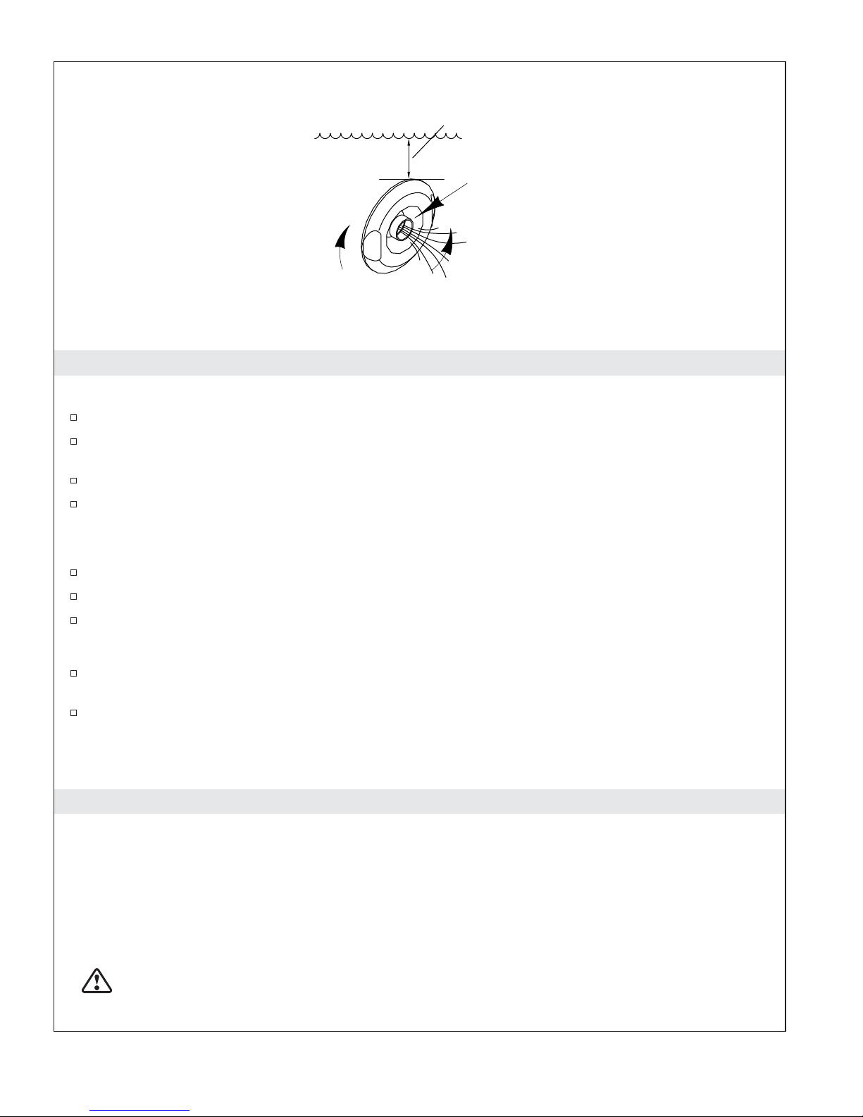
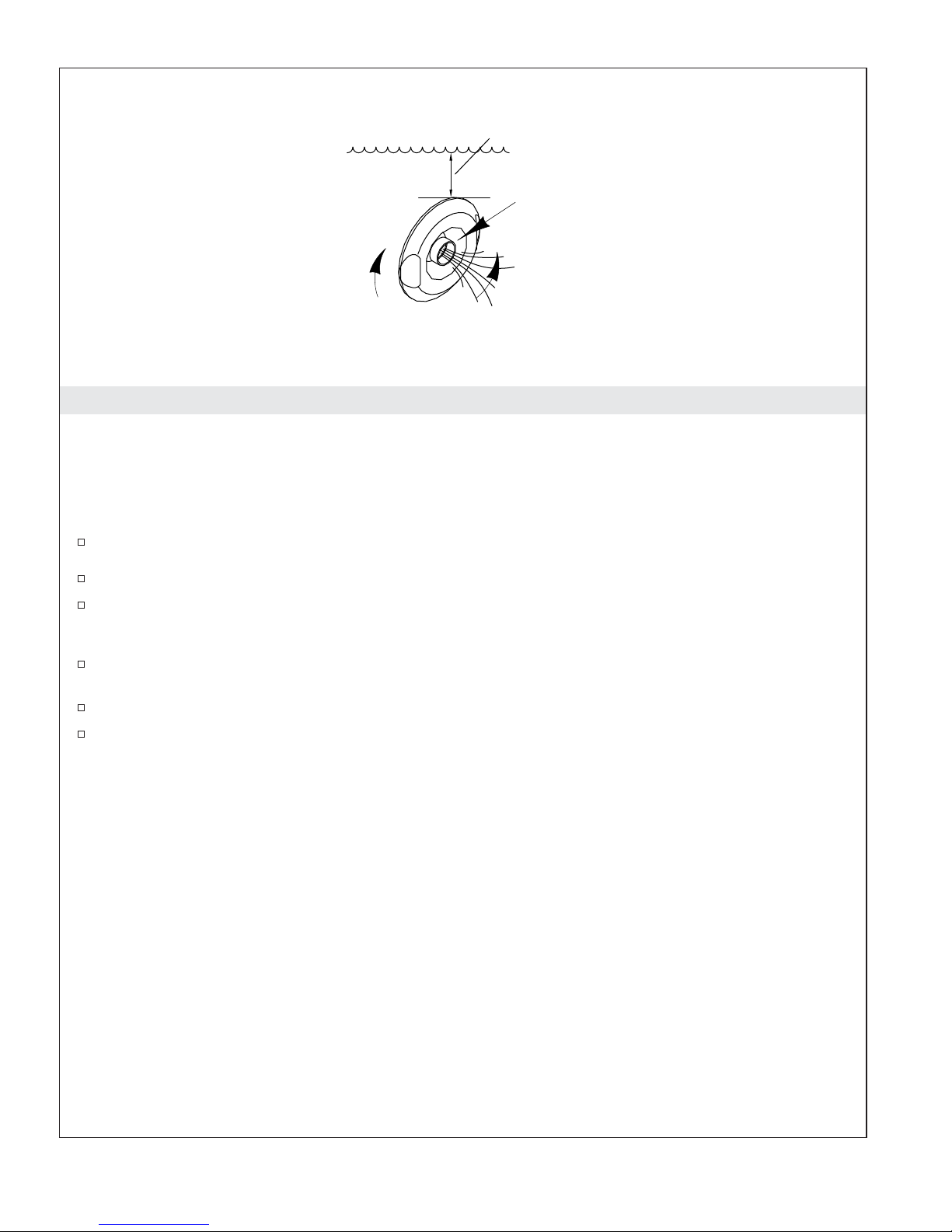
Fill with water at least 2" (51 mm)
above the highest jet.
Turn the jet trim ring
clockwise to
decrease the flow.
Turn the jet trim ring counterclockwise
to increase the flow.
Position the jet
nozzles to direct
the water flow as
desired.
5. Complete the Installation
Test Run the Bath
Fill the bath at least 2″ (51 mm) above the top of the highest jet.
Turn off the bath and let sit for five minutes. Check all piping connections for leaks. Check for
leakage along the front, sides, and back of the bath.
Turn on the blower and run for 5 minutes. Check for proper operation and function.
For additional information on bath operation, see the ″Operating the Whirlpool System″ and
″Operating the Air System″ sections.
Finish the Installation
Install water-resistant wallboard and all finished wall, deck, and floor materials.
Apply silicone sealant to seal all areas where the bath and finished wall or deck meet.
Install the faucet trim.
Clean-up After Installation
When cleaning up after installation, do not use abrasive cleansers, as they may scratch and dull the
bath surface. Use warm water and a liquid detergent to clean the surface of the bath.
Remove stubborn stains or paint with turpentine or paint thinner. Do not allow cleaners containing
petroleum distillates to remain in contact with any bath surface for long periods of time. Remove
plaster by carefully scraping with a wood edge. Do not use metal scrapers, wire brushes, or other
metal tools. Use a powder-type detergent on a damp cloth to provide mild abrasive action to any
residual plaster.
Important Safety Instructions
READ AND FOLLOW ALL INSTRUCTIONS
SAVE THESE INSTRUCTIONS
INSTRUCTIONS PERTAINING TO A RISK OF FIRE, ELECTRIC SHOCK, OR INJURY TO PERSONS
WARNING: When using electrical products, basic precautions should always be followed,
including the following:
Kohler Co. 9 1208027-2-F
Important Safety Instructions (cont.)
DANGER: Risk of accidental injury or drowning. To reduce the risk of injury, do not permit
children to use this unit unless they are closely supervised at all times.
WARNING: Risk of personal injury. To avoid injury, exercise care when entering or exiting the
bath.
WARNING: Risk of electric shock. Do not permit electric appliances (such as a hair dryer, lamp,
telephone, radio, or television) within 5’ (1.5 m) of this bath.
WARNING: The use of alcohol, drugs, or medication can greatly increase the risk of fatal
hyperthermia. Prolonged immersion in hot water may induce hyperthermia. Hyperthermia occurs
when the internal temperature of the body reaches a level several degrees above the normal body
temperature of 98.6°F (37°C). The symptoms of hyperthermia include an increase in the internal
temperature of the body, dizziness, lethargy, drowsiness, and fainting. The effects of hyperthermia
include: (a) failure to perceive heat, (b) failure to recognize the need to exit the bath, (c)
unawareness of impending hazard, (d) fetal damage in pregnant women, (e) physical inability to
exit the bath, and (f) unconsciousness resulting in the danger of drowning.
WARNING: Risk of fetal injury. Pregnant or possibly pregnant women should consult a physician
before using the bath.
WARNING: Risk of hyperthermia or drowning. Do not use the bath immediately following
strenuous exercise.
WARNING: Risk of hyperthermia or drowning. Water temperature in excess of 100°F (38°C) may
cause injury. Test and adjust the water temperature before use.
WARNING: Risk of personal injury. Never drop or insert any object into any opening.
Use this bath only for its intended purpose as described in this guide. Do not use attachments not
recommended by Kohler Co.
The bath must be connected only to a supply circuit that is protected by a Ground-Fault Circuit-Interrupter
(GFCI)*. Such a GFCI should be provided by the installer and should be tested on a routine basis. To test the
GFCI, press the test button. The GFCI should interrupt power. Press the reset button. Power should be
restored. If the GFCI fails to operate in this manner, the GFCI is defective. If the GFCI interrupts power to
the bath without the test button being pressed, a ground current is flowing, indicating the possibility of an
electric shock. Do not use this bath. Disconnect the bath and have the problem corrected by a qualified
service representative before using.
Flush your whirlpool system twice a month or more depending upon usage, as described in the ″Flush the
System″ section of this guide.
Repeated use of personal care products containing oils can damage plastic whirlpool components. Avoid
using bath oils.
Whirlpool hydro-massage action can cause even a small amount of bubble bath, bath soap, shampoo, or bath
oil to foam excessively. For this reason, please do not use these products during whirlpool operation.
*Outside North America, this device may be known as a Residual Current Device (RCD).
1208027-2-F 10 Kohler Co.
Fill with water at least 2" (51 mm)
above the highest jet.
Turn the jet trim ring
clockwise to
decrease the flow.
Position the jet
nozzles to direct
the water flow as
desired.
Turn the jet trim ring counterclockwise
to increase the flow.
Operating the Whirlpool System
NOTE: This is a combination whirlpool bath with airjets. For information on using the air features, refer
to the ″Operating the Air System″ section.
Start/Stop the Whirlpool Jets
NOTE: The water temperature in the bath should never exceed 104°F (40°C).
Close the drain, then fill the bath at least 2” (51 mm) above the top of the highest jet.
Use your hand to test the water temperature for comfort and safety, then carefully enter the bath.
Press the air switch to turn on the pump.
NOTE: If equipped, the heater will automatically turn on.
Adjust the jets for optimum air/water mixture. Turn the jet trim rings clockwise to reduce the flow
or counterclockwise to increase the flow. Position the jet nozzles to direct the water flow as desired.
Press the air switch a second time to turn off the pump.
Carefully exit the bath, then open the drain and empty the water.
NOTE: If the whirlpool system does not function properly, refer to the ″Troubleshooting″ section.
Kohler Co. 11 1208027-2-F
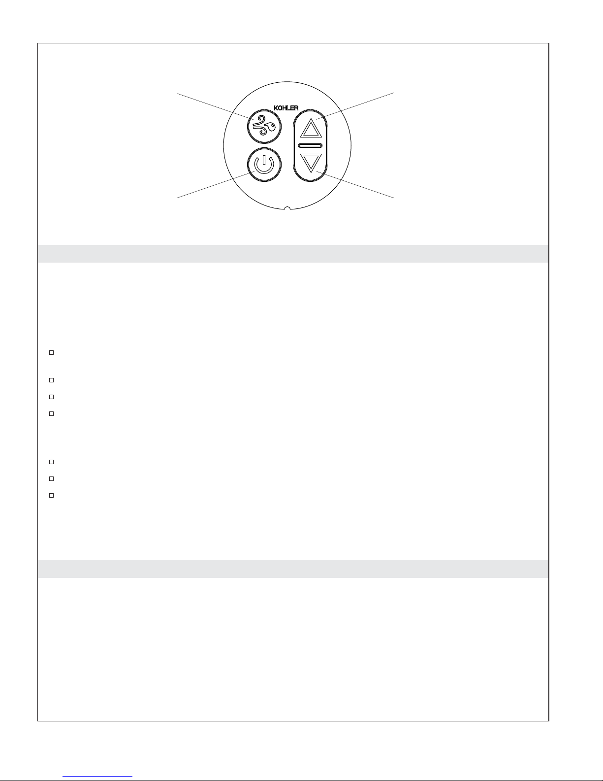
Purge Mode
Increases Flow
On/Off
Decreases Flow
Operating the Air System
NOTE: This is a combination whirlpool bath with airjets. For information on using the whirlpool features,
refer to the ″Operating the Whirlpool System″ section.
IMPORTANT! This product contains an automatic water purge mode that turns the blower on for 2
minutes approximately 30 minutes after the unit is turned off and drained.
NOTE: The water temperature in the bath should never exceed 104°F (40°C).
Close the drain, then fill the bath at least 2” (51 mm) above the highest whirlpool jet to provide
adequate water supply for the air system.
Use your hand to test the water temperature for comfort and safety, then carefully enter the bath.
Press the [On/Off] icon to turn the blower on at medium speed.
Press the [Up] or [Down] arrow icons to increase or decrease the air flow.
NOTE: The blower will turn off automatically following 20 minutes of operation, and can be immediately
restarted if desired.
Press the [On/Off] icon a second time to turn off the blower.
Carefully exit and drain the bath.
Press the [Purge Mode] icon to blow remaining water from the air channels. The blower will turn
on for 2 minutes and then turn off automatically.
NOTE: About 30 minutes after the blower motor stops, a 2 minute purge mode will automatically start.
NOTE: If the bath does not function properly, refer to the ″Troubleshooting″ section.
Care and Cleaning
For best results, keep the following in mind when caring for your KOHLER bath:
•
Always test your cleaning solution on an inconspicuous area before applying to the entire surface.
•
Do not use abrasive cleansers or solvents. Abrasive cleaners and solvents can damage the product
surface.
•
Wipe surfaces clean and rinse completely with water immediately after applying cleaner. Rinse and
dry any overspray that lands on nearby surfaces.
•
Do not allow cleaners to soak on surfaces.
•
Use a soft, dampened sponge or cloth. Never use an abrasive material such as a brush or scouring
pad to clean surfaces.
1208027-2-F 12 Kohler Co.

Care and Cleaning (cont.)
•
The ideal cleaning technique is to rinse thoroughly and blot dry any water from the surface after
each use.
Maintaining the Airjets
If cleaning the airjets is necessary due to hard water deposits, wet a soft, non-abrasive cloth with
white vinegar and wipe the plugged airjet holes. Immediately rinse the area with clean water to
avoid long-term exposure of the vinegar to the airjet surface.
Fill the bath with water to the top row of airjets. Drain the bath and press the purge button.
Cleaning Your User Keypad
Use a soft cloth to wipe the keypad after each use. If the surface becomes dirty, use a non-abrasive
soap and warm water to clean.
For detailed cleaning information and products to consider, visit www.kohler.com/clean. To order Care &
Cleaning information, call 1-800-456-4537.
Flush the System
NOTE: Flush your whirlpool system twice a month or more, depending upon usage.
Turn the jet trim rings fully clockwise to reduce air induction.
Fill the whirlpool with hot water to a level at least 2″ (51 mm) above the highest jet.
Add 2 teaspoons (10 ml) of a low-foaming, powder automatic dishwasher detergent and 20 ounces
(590 ml) of household bleach (5% - 6% sodium hypochlorite) to the water.
Run the whirlpool for 5 to 10 minutes. Turn off the whirlpool and drain.
If desired, rinse the bath surfaces with water.
Rinse the surfaces of the jets, faucet, grab bars, and drain, and wipe them dry with a soft cloth.
Kohler Co. 13 1208027-2-F
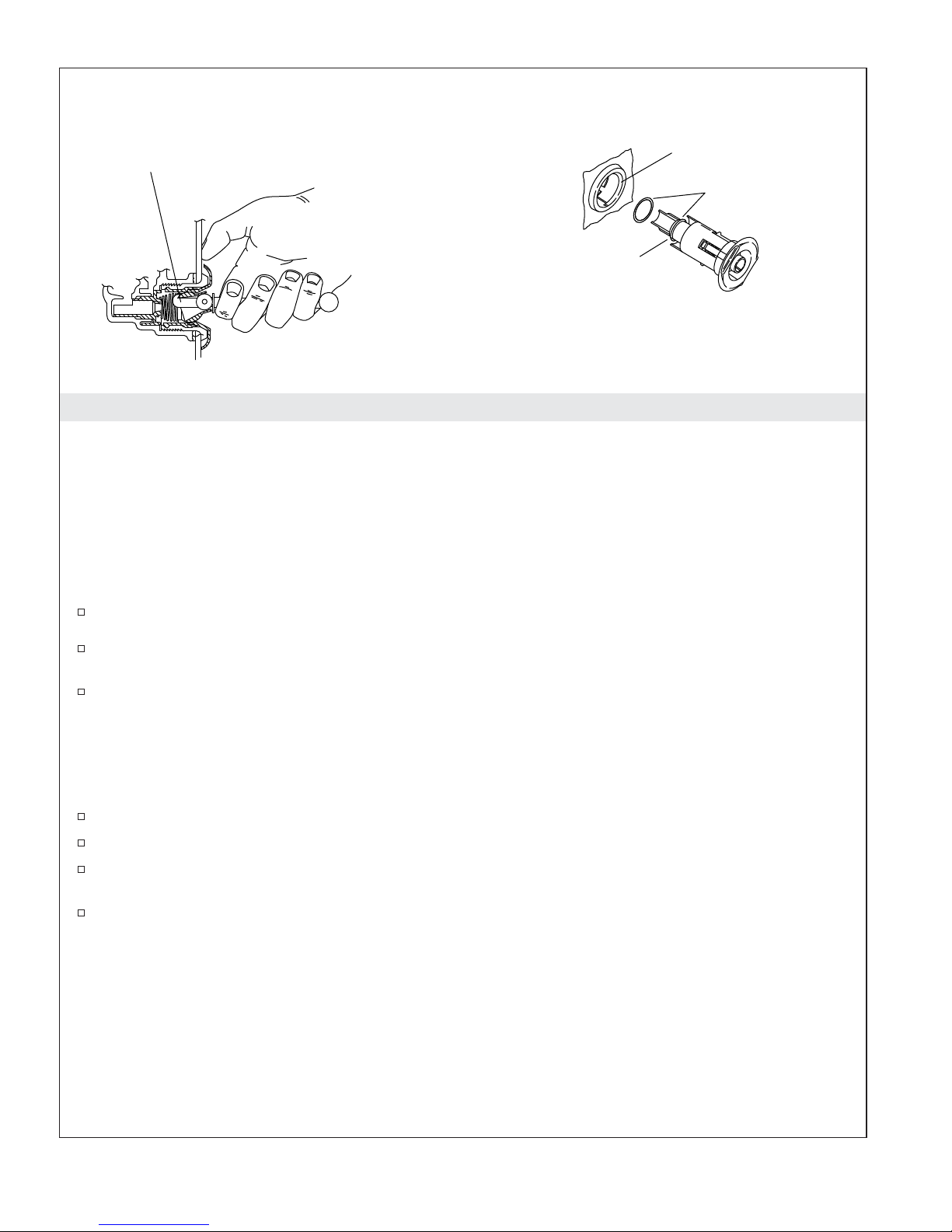
Remove the Jets
Reinstall the Jets
Insert the tool hook as shown and pull the jet out of the
housing. The jet should be facing up when this is done.
Housing
Inspect and
lubricate the O-ring.
Slide the O-ring
onto the first
shoulder of the jet.
Insert the jet into the housing, and lightly
push and rotate until it snaps in position.
Troubleshooting
NOTICE: This section is for general aid only. A Kohler Co. Authorized Service Representative or
qualified electrician should correct any electrical problems. For warranty service, call 1-800-4KOHLER
from within the USA and Canada, or 001-800-456-4537 from within Mexico.
For service parts information, visit your product page at www.kohler.com/serviceparts.
Remove the Jets
NOTE: A special tool is provided with the replacement jets that will allow you to remove the jets from
the whirlpool. This tool is also supplied with each trim kit.
Position the jet ball nozzle so it is pointing upward.
Insert the removal tool, hooked end up, into the opening of the jet and hook the inside top of the
nozzle.
Grasp the tool firmly and place your thumb against the whirlpool wall. Pull steadily on the tool
until the jet assembly pulls free of the hole. Be careful not to lose the O-ring.
Reinstall the Jets
NOTE: To allow easy rotation and proper operation of the jet, the O-ring must be: (1) correctly positioned,
(2) lubricated, and (3) in good condition.
Install the O-ring onto the first shoulder of the jet.
Using the silicone lube packet (provided), lubricate the O-ring to prevent noisy operation of the jet.
Carefully insert the jet into the housing, then lightly push and rotate the jet until it snaps into
position. Do not force the jet.
Verify the jet is installed correctly. The jet should turn smoothly both clockwise and
counterclockwise. Remove and reinstall, if necessary.
1208027-2-F 14 Kohler Co.
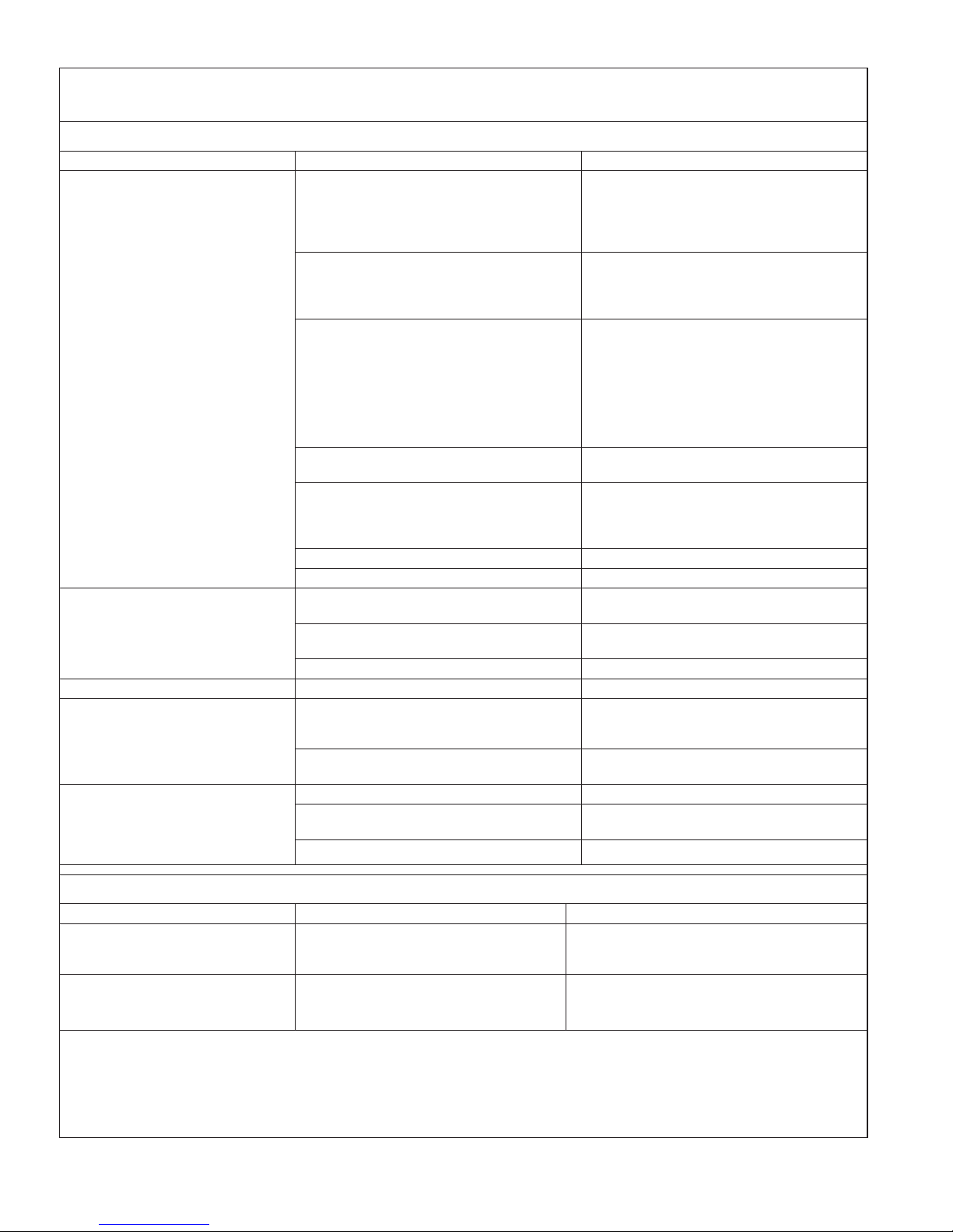
Troubleshooting (cont.)
Whirlpool System
Symptoms Probable Causes Recommended Action
1. Whirlpool does not start
or stop.
A. No power to motor. A. Check that the pump and heater
are plugged in and that the GFCI
or RCD is switched to the correct
position. Plug in or reset the
GFCI/RCD as needed.
B. Air hose is loose or disconnected. B. Check that the hose is connected
at both the receiver/pump end
and to the air switch. Reconnect
if needed.
C. Air hose is pinched or kinked. C. Adjust hose to clear the
pinched/kinked area. If the
tubing is pinched/kinked and
cannot be readjusted, or no
noticeable pinch/kink is
apparent, poke a small hole in
the tubing with a tack and try
the system again.
D. Push button assembly is damaged. D. Replace the push button
assembly.
E. Push button has grease in the
bleed area.
E. Disassemble the push button
assembly and wipe away any
excess grease. Reassemble the
button and retry the system.
F. Air hose is damaged. F. Replace the air hose.
G. Motor/pump does not work. G. Replace the motor/pump.
2. Motor starts, not all jets
are functioning.
A. Jet is closed. A. Rotate jet trim ring
counterclockwise to open.
B. Jet not installed correctly. B. Reinstall jet; check for O-ring
damage.
C. Jets are blocked. C. Remove blockage.
3. Pump does not prime. A. Pump shimmed too high. A. Lower pump support bracket.
4. Noisy operation. A. Pump banding straps have not
been cut. (Models with support
A. Cut pump banding straps with
tin snips.
blocks only.)
B. Jet O-ring dislodged. B. Remove jet, replace and lubricate
O-ring, and reinstall jet.
5. Heater does not operate.
(“H” models only)
A. No power to heater. A. Reset the GFCI or RCD.
B. Water temperature exceeds 104°F
(40°C).
B. Allow water to cool and heater
will re-engage.
C. Heater does not work. C. Replace heater.
Air System
Symptoms Probable Causes Recommended Action
1. Blower turns on by itself
A. Normal operation. Automatic
after the bath has been
drained.
2. Blower turns off by itself
A. The Purge Mode icon was
after running for two
minutes.
Kohler Co. 15 1208027-2-F
purge mode is working as
designed.
pressed instead of the On/Off
icon.
A. No action is required. Automatic
purge mode runs for 2 minutes 30
minutes after the bath is drained.
A. Press the On/Off icon on the
keypad. See the ″Operating
Instructions″ section.

Troubleshooting (cont.)
Air System
Symptoms Probable Causes Recommended Action
3. Blower motor will not
start.
4. Blower motor stops
running and will not
immediately restart.
5. Blower motor starts, some
but not all airjets are
working.
6. Blower motor runs but no
air bubbles are observed.
7. Blower motor operates,
air bubbles are observed,
but speed feature does
not work.
8. Blower motor does not
turn off when the On/Off
button is pressed.
9. Purge mode does not
work.
10. Bath does not purge
automatically.
A. Power cord from blower motor
is loose, disconnected, or
damaged.
B. User keypad cable loose or
damaged.
C. User keypad does not work. C. Replace user keypad.
D. Blower motor does not work. D. Replace the blower motor.
A. Blower motor overheated and
protection device activated.
A. Blower motor speed is too low. A. Increase speed.
B. Blower motor inlet is blocked. B. Clean blower motor inlet.
C. Blower motor does not work. C. Replace the blower motor.
D. Blower motor discharge is
blocked.
E. Airjets are clogged. E. Use a small between-the-teeth
A. Blower motor inlet is blocked. A. Clean blower motor inlet.
B. Airjets are clogged. B. Use a small between-the-teeth
C. Blower motor does not work. C. Replace the blower motor.
A. Blower motor inlet is blocked. A. Clean blower motor inlet.
B. Loose, disconnected, or
damaged wiring harness.
C. User keypad does not work. C. Replace the user keypad.
D. Blower motor does not work. D. Replace the blower motor.
A. User keypad does not work. A.
B. Loose, disconnected, or
damaged wiring harness.
C. Control does not work. C. Replace the control.
A. User keypad does not work. A. Replace the user keypad.
B. Control does not work. B. Replace the control.
A. Blower does not work. A. Replace the blower.
A. Check wiring for proper
connections.
B. Check wire connections. If
necessary, replace user keypad
cable.
A. Check for blockage at blower air
intake. Remove blockage and allow
motor to cool.
D. Clear blockage.
dental brush and white vinegar.
Dip the brush in the vinegar, brush
the hole, rinse the brush in clean
water, and then use the wet rinsed
brush to rinse the hole.
dental brush and white vinegar.
Dip the brush in the vinegar, brush
the hole, rinse the brush in clean
water, and then use the wet rinsed
brush to rinse the hole.
B. Check wiring for proper
connections. Replace the wiring
harness if necessary.
Replace the user keypad.
B. Check wiring for proper
connections. Replace the wiring
harness if necessary.
Warranty
ONE-YEAR LIMITED WARRANTY
KOHLER plumbing products are warranted to be free of defects in material and workmanship for one year
from date of installation.
1208027-2-F 16 Kohler Co.

Warranty (cont.)
Kohler Co. will, at its election, repair, replace or make appropriate adjustment where Kohler Co. inspection
discloses any such defects occurring in normal usage within one (1) year after installation. Kohler Co. is not
responsible for removal or installation costs. Use of in-tank toilet cleaners will void the warranty.
To obtain warranty service contact Kohler Co. either through your Dealer, Plumbing Contractor, Home
Center or E-tailer, or by writing Kohler Co., Attn.: Customer Care Center, 444 Highland Drive, Kohler, WI
53044, USA, or by calling 1-800-4-KOHLER (1-800-456-4537) from within the USA and Canada, and
001-800-456-4537 from within Mexico, or visit www.kohler.com within the USA, www.ca.kohler.com from
within Canada, or www.mx.kohler.com in Mexico.
IMPLIED WARRANTIES INCLUDING THAT OF MERCHANTABILITY AND FITNESS FOR A
PARTICULAR PURPOSE ARE EXPRESSLY LIMITED IN DURATION TO THE DURATION OF THIS
WARRANTY. KOHLER CO. AND/OR SELLER DISCLAIM ANY LIABILITY FOR SPECIAL,
INCIDENTAL OR CONSEQUENTIAL DAMAGES. Some states/provinces do not allow limitations on how
long an implied warranty lasts, or the exclusion or limitation of special, incidental or consequential damages,
so these limitations and exclusions may not apply to you. This warranty gives you specific legal rights. You
may also have other rights which vary from state/province to state/province.
This is Kohler Co.’s exclusive written warranty.
Warranty
For Mexico
KOHLER CO.
It is recommended that at the time of purchase, you verify that all accessories and components are complete
in this package.
This Kohler product is warranted to be free of defects in material and workmanship for one (1) year from the
date of purchase as shown on the invoice or receipt.
1. Kohler Co. will only service its commercialized products through its authorized distributors.
2. To obtain warranty service, please present the invoice and corresponding warranty.
3. Through its authorized distributors, Kohler Co. promises to repair the defective product or provide a new
replacement or an equivalent model (in those cases that the model has been discontinued) when the product
is beyond repair, without any charge to the consumer.
4. The time of repair will not exceed six (6) weeks commencing on the date the product is received.
5. It is recommended that the consumer save the invoice or receipt as additional protection, as it may
substitute the warranty in the case that there is a discrepancy in the validity of the warranty.
EXCEPTIONS AND RESTRICTIONS
The Warranty will not be valid in the following cases:
1. When the product is not operated in accordance with the instructions concerning use and operation set
forth in the owner’s manual or installation instructions, and when the recommendations and warnings
included are not observed.
2. When the product has been modified or dismantled partially or totally; or has been used in a negligent
fashion and as a consequence has suffered damages attributable to the consumer, individual, or hardware not
authorized by Kohler Co.
3. This warranty does not cover the damages as a result of disaster such as fire or acts of God, including
flooding, earthquake, or electric storms, etc. To obtain a list of distributors in your area where you can
exercise your rights under this warranty, please call 001-800-456-4537.
KOHLER CO., KOHLER, WI 53044 U.S.A.
IMPORTER:
Kohler Co. 17 1208027-2-F
 Loading...