

Page 1
BODYSPA
PERSONAL HYDRO-MASSAGE SYSTEM
K-1000, K-1015/16, K-5161-L
IMPORTANT! READ THIS BEFORE YOU BEGIN
This BodySpa operates at flow rates up to 80 gallons per
minute. To achieve a watertight installation, it is critical
that you follow all the installation instructions carefully.
Pay particular attention to leveling and sealing details to
obtain a satisfactory installation.
IMPORTANT INFORMATION
WARNING: When using electrical products,
basic precautions should always be followed,
including the following:
DANGER: Risk of electrical shock. Connect only
to a circuit protected by a Ground-Fault
Circuit-Interrupter (GFCI).
Grounding is required. The unit should be installed and
grounded by a qualified service representative.
Building materials and wiring should be routed away from
the pump body and other heat-producing components of
the unit.
10-JET ALCOVE
Install to permit access for servicing.
TABLE OF CONTENTS
PRODUCT NOTICES 2. . . . . . . . . . . . . . . . . . . . . . . . .
PRODUCT REQUIREMENTS 2. . . . . . . . . . . . . . . . . .
SITE REQUIREMENTS 3. . . . . . . . . . . . . . . . . . . . . . . .
BEFORE INSTALLING FOOTBATH 4. . . . . . . . . . . . .
INSTALL THE FOOTBATH 4. . . . . . . . . . . . . . . . . . . . .
BEFORE INSTALLING TOWER 7. . . . . . . . . . . . . . . . .
ELECTRICAL CONNECTIONS 9. . . . . . . . . . . . . . . . .
INSPECT CONNECTIONS 9. . . . . . . . . . . . . . . . . . . . .
DOOR ENCLOSURE PREP ARATION 10. . . . . . . . . . .
INST ALL THE ENCLOSURE 10. . . . . . . . . . . . . . . . . . .
INSTALL THE TOWER 19. . . . . . . . . . . . . . . . . . . . . . . .
COMPLETE INSTALLATION 21. . . . . . . . . . . . . . . . . . .
INSTALL THE SEAT 23. . . . . . . . . . . . . . . . . . . . . . . . . . .
WATER TEST FOOTBATH AND TOWER 23. . . . . . . .
CLEAN-UP AFTER INSTALLATION 23. . . . . . . . . . . . .
CONFIRM PROPER OPERA TION 24. . . . . . . . . . . . . .
116290-2-AB
2001 Kohler Co.
Page 2

1. PRODUCT NOTICES
A. INST ALLER HAZARD NOTIFICA TION
WARNING: Risk of electrical shock. A licensed
electrician should make all electrical connections.
WARNING: Risk of electrical shock. Connect only
to a circuit protected by a Ground-Fault
Circuit-Interrupter (GFCI).
WARNING: Risk of electrical shock. Disconnect
power before servicing.
WARNING: Risk of injury or property damage.
Please read all instructions thoroughly before
beginning installation, including the following
Product Requirements.
NOTICE: Follow all local plumbing and electrical
codes.
C. PRODUCT MODIFICA TIONS
All information in this manual is based upon the latest
product information available at the time of publication.
Kohler Co. reserves the right to make changes in product
characteristics, packaging, or availability at any time
without notice.
WARNING: Unauthorized modification may
cause unsafe operation and poor performance
of the BodySpa. Do not relocate the pump or make
other modifications to the BodySpa system, as this
could adversely affect the performance and safe
operation of the unit. Kohler Co. shall not be liable
under its warranty or otherwise for personal injury or
damage caused by any such unauthorized
modification.
B. FACT ORY -ASSEMBLED FEA TURES
Factory installed components include pump with integral
heater, control, and power supply cord.
The pump and piping are factory-assembled.
The BodySpa is not designed for steam applications, and
may not perform satisfactorily as a steam unit.
2. PRODUCT REQUIREMENTS
A. PRODUCT INSPECTION
The BodySpa door enclosure, footbath, and tower are
specifically designed for this installation. Before
proceeding with the installation, check the model
numbers of the footbath, tower, and door enclosure. The
door enclosure, tower, and footbath model numbers are
provided in the roughing-in information packed with the
product.
Carefully unpack and inspect the footbath and tower for
damage. Do not unpack the door enclosure until
instructed to do so. Leave all materials in the cartons
during construction to prevent damage.
NOTICE: Make sure the union connection to the
pump inlet is securely tightened.
B. CONNECTIONS AND SERVICE ACCESS
Before installation, ensure proper access to the final
connections.
NOTICE: Provide unrestricted service access to the
pump. An access panel must be constructed to allow for
sufficient clearance for servicing the pump or controls.
The access panel must be located immediately next to the
pump. Refer to the roughing-in information packed with
the product and the stud framing preparation on Page 3.
116290-2-AB
2
Kohler Co., Kohler WI U.S.A.
Page 3

C. ELECTRICAL REQUIREMENTS
The installation must have a Class A Ground-Fault
Circuit-Interrupter (GFCI). The GFCI protects against
line-to-ground shock hazard. Use a 120 V, 20 A, 60 Hz
dedicated service for the BodySpa.
3. SITE REQUIREMENTS
A. CLEARANCE REQUIREMENTS
The distance from the rough floor to the finished ceiling or
header must be between 83-1/2” and 84” to provide
adequate clearance when assembling the door enclosure
to the footbath. Be sure the ceiling and header are level.
B. STUD POCKET PREP ARA TION
NOTE: Carefully study the illustration at right before you
begin construction of the stud pocket. Follow the framing
details provided to ensure correct installation.
Use 2x6 framing for the tower wall to provide sufficient
space for the tower mounting frame and wiring, and
minimum 2x4 framing for the rest of the stud pocket. Make
sure you allow for access to the pump in the event the
BodySpa requires service.
Provide double stud support for the door enclosure wall
jambs. You must secure the door enclosure wall jambs
directly to the studs to obtain proper support and correct
opening dimensions. Expanding wall anchors will not
provide adequate support for the door enclosure
assembly.
You must install these stud supports to be within 3/8”
of plumb for proper door enclosure installation. Maintain
this tolerance to ensure a satisfactory, watertight
installation.
The footbath requires no additional bottom support when
the rough floor is plumb and level with respect to the stud
framing. If the rough floor is not level, shim it as needed.
Verify that the distance from the rough floor to the finished
ceiling is between 83-1/2” and 84”.
15-11/16”
31-7/8”
DOUBLE STUD
(REQUIRED FOR
ENCLOSURE
INST ALLATION)
54”
16”
PROVIDE
ACCESS
TO DRAIN
2x6 STUDS
9-3/4”
12”
PUMP/
CONTROL
ACCESS
DOUBLE STUD
(REQUIRED FOR
ENCLOSURE
INST ALLATION)
83-1/2”
to 84”
IMPORTANT: Leave studs exposed. You must secure
the door enclosure wall jambs directly to the studs. Under
no circumstances install the finished wall material until
instructed.
If grab bars will be installed, provide backing to the
framing.
C. PLUMBING PREP ARA TION
Position the plumbing according to the roughing-in
dimensions. Cap the supplies, and check for leaks.
Kohler Co., Kohler WI U.S.A.
10-3/4”
ROUGH FLOOR
3
116290-2-AB
Page 4

4. BEFORE INSTALLING FOOTBATH
Install the drain to the footbath according to the drain
manufacturer’s instructions. When installing the drain
overflow tube and hood, be sure to adequately seal along
the edges of the hood to prevent leakage.
5. INSTALL THE FOOTBATH
A. CONFIRM STUD POCKET ROUGH-IN
The door enclosure is specifically designed for this
footbath. For proper installation, make sure the double
studs for the wall jambs are in position before installing the
unit. Proper door enclosure assembly depends upon
installation of the footbath against square and plumb (to
within 3/8”) studding. Verify this before proceeding with
the installation.
B. INST ALL THE FOOTBA TH
1. The variable flow valve assembly is attached to the
suction line of the footbath harness for shipping, and
the wires are connected to the pump. Cut the
strapping, and remove the variable flow valve
assembly. Remove and discard the plug on the end
of the pump union. Then temporarily connect the
variable flow valve to the pump by loosely threading
the union nut to the pump discharge union.
2. Set the footbath on the subfloor. Align the trap with
the tailpiece.
Variable Flow
V alve Assembly
Pump
3. Position a clean drop cloth in the footbath to prevent
damage.
4. Level the unit using the footbath rim surfaces. Do not
use the nailing-in flange to level the unit. The
footbath must be level to properly install and operate
the door enclosure.
5. Securely shim under the wood blocks as needed.
Secure the footbath to the studding using the
nailing-in flange and galvanized drywall screws. Drill
and countersink pilot holes halfway up the nailing-in
flange. Drill from the finished side of the nailing-in
flange to prevent chipping of the acrylic.
6. Add furring strips to the stud framing inside the
recess area. This will make the studs even with the
footbath nailing-in flange.
Nailing-In
Flange
116290-2-AB
4
Kohler Co., Kohler WI U.S.A.
Page 5
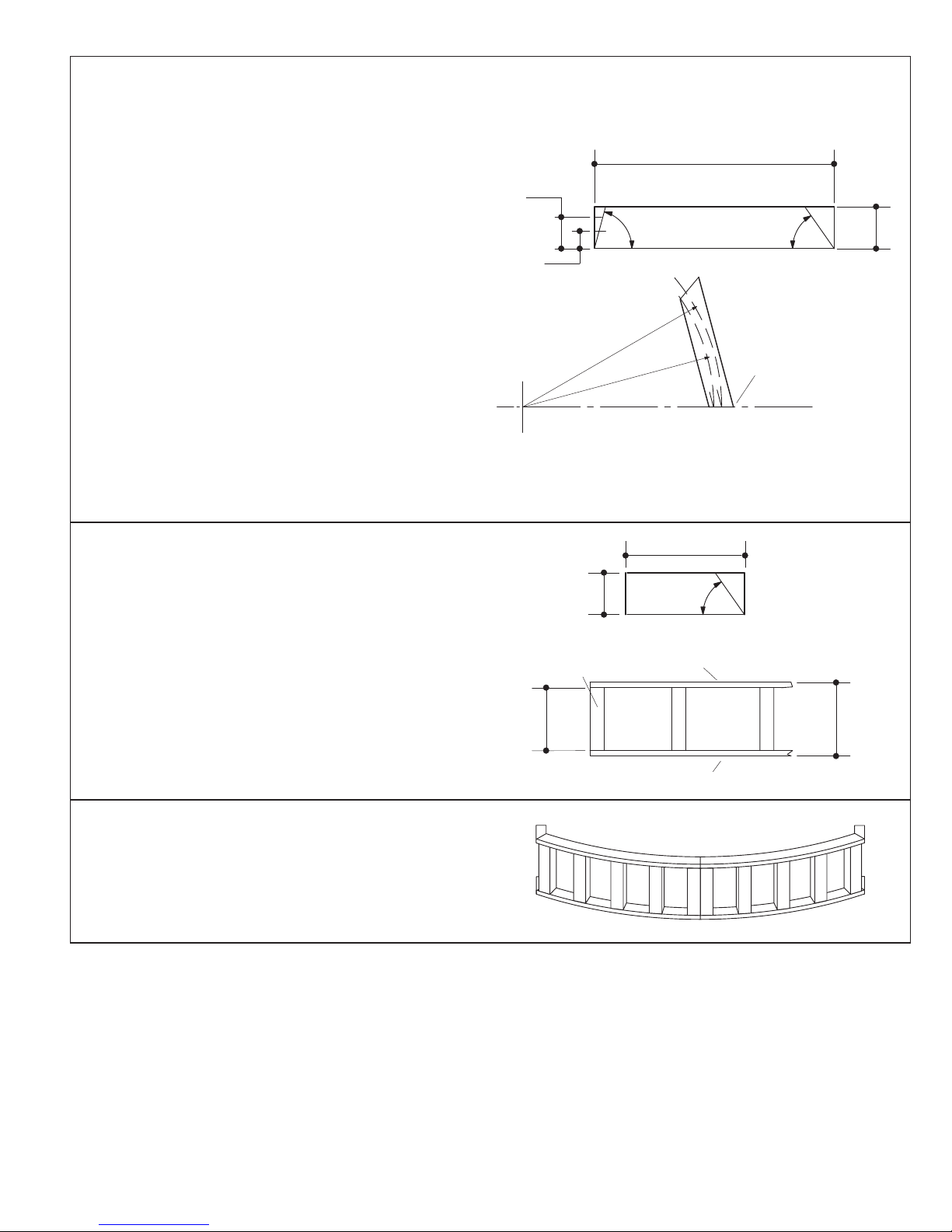
C. CONSTRUCT THE APRON
NOTE: Kohler Co. recommends this procedure for
constructing a BodySpa apron. Other methods can be
used to obtain an acceptable result.
1. Cut four 3/4” plywood boards to 6” x 34-1/4”.
Measure and cut a 55 taper at one end of each
board, and a 75 taper at the other end. Both ends
must taper to the same side.
5”
34-1/4”
75 55
6”
2. Draw a pencil mark 3” from the long side of one of the
boards at the 75 taper end. Draw a second mark 5”
from the long side, as shown.
3. Use a pencil, string, and nail to carefully draw a
51-1/4” radius (for 1/2” thick finished wall) across the
full length of the board at the 3” pencil mark. For
different finished wall thickness, adjust this radius
accordingly. Draw a 49-1/4” radius across the 5”
pencil mark.
4. Use a saber saw to cut the plywood along the radius
lines.
5. Use this board as a template to mark and cut the
other three plywood boards.
6. Cut four 3/4” plywood boards to 2” x 6”, with a 50
taper on one end.
7. Cut twelve 2x2 studs 9” long.
8. Assemble the apron frame sections as shown.
3”
2x2 Studs
51-1/4” R.
49-1/4” R.
2”
3/4” Plywood
Measure 3” and 5”
Down From This
Edge
6”
50
9. Position the apron frame sections under the footbath
rim so the 75 tapered ends of the curved sections
touch. Align the apron frame sections so they are
recessed correctly for the finished apron wall
thickness. Make sure the sections are plumb.
10. Secure the apron frame sections to the floor.
9”
10-1/2”
3/4” Plywood
Kohler Co., Kohler WI U.S.A.
5
116290-2-AB
Page 6
D. TOWER MOUNTING FRAME PREP ARA TION
On one of the tower mounting studs, draw a pencil line
exactly 2-3/8” up from the flat surface of the seat deck. Y ou
will use this mark to position the tower mounting frame at
the correct height. Be precise with this measurement.
2-3/8”
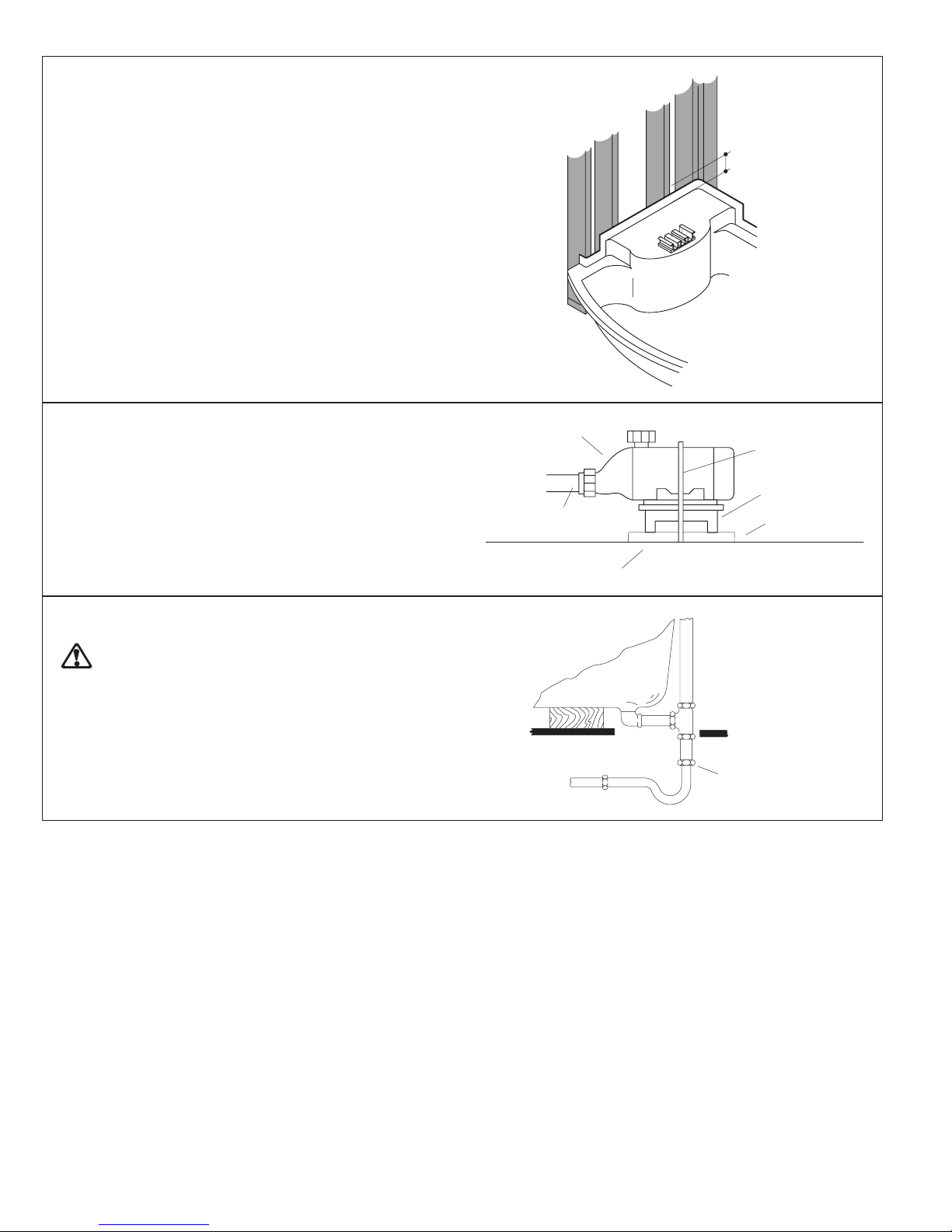
E. PUMP BANDING STRAP CUT
NOTICE: This step is necessary to make your Kohler
BodySpa operate more quietly.
Use tin snips to cut the banding strap. When the banding
strap is cut, the pump base and pump will continue to rest
upon the plywood ledge that extends from under the
footbath.
F . INST ALL PLUMBING
CAUTION: Risk of damage to footbath bottom
and subfloor. Ensure a watertight seal on the
footbath drain connections.
When the footbath is securely positioned, connect and
leak test the drain and fittings.
NOTE: An access panel will simplify future
maintenance.
Pump
Suction Line
Banding Strap
Pump Base
Plywood
Ledge
Subfloor
Connect Here
116290-2-AB
6
Kohler Co., Kohler WI U.S.A.
Page 7

6. BEFORE INSTALLING TOWER
A. INST ALL THE MOUNTING FRAME
Remove three 3/8” tower bolts from the locations shown,
and carefully lift the tower out of the mounting frame.
Carefully set the tower aside where it will not be damaged.
Set the mounting frame between the tower mounting
studs, and line up the bottom metal edge with the pencil
line you drew on one of the studs.
Secure the mounting frame to the tower mounting studs
with ten stainless steel drywall screws provided.
Mounting
Stud
Mounting
Frame
Pencil
Line
Bolts
Bolt
Stainless
Steel Drywall
Screw
Kohler Co., Kohler WI U.S.A.
7
116290-2-AB
Page 8
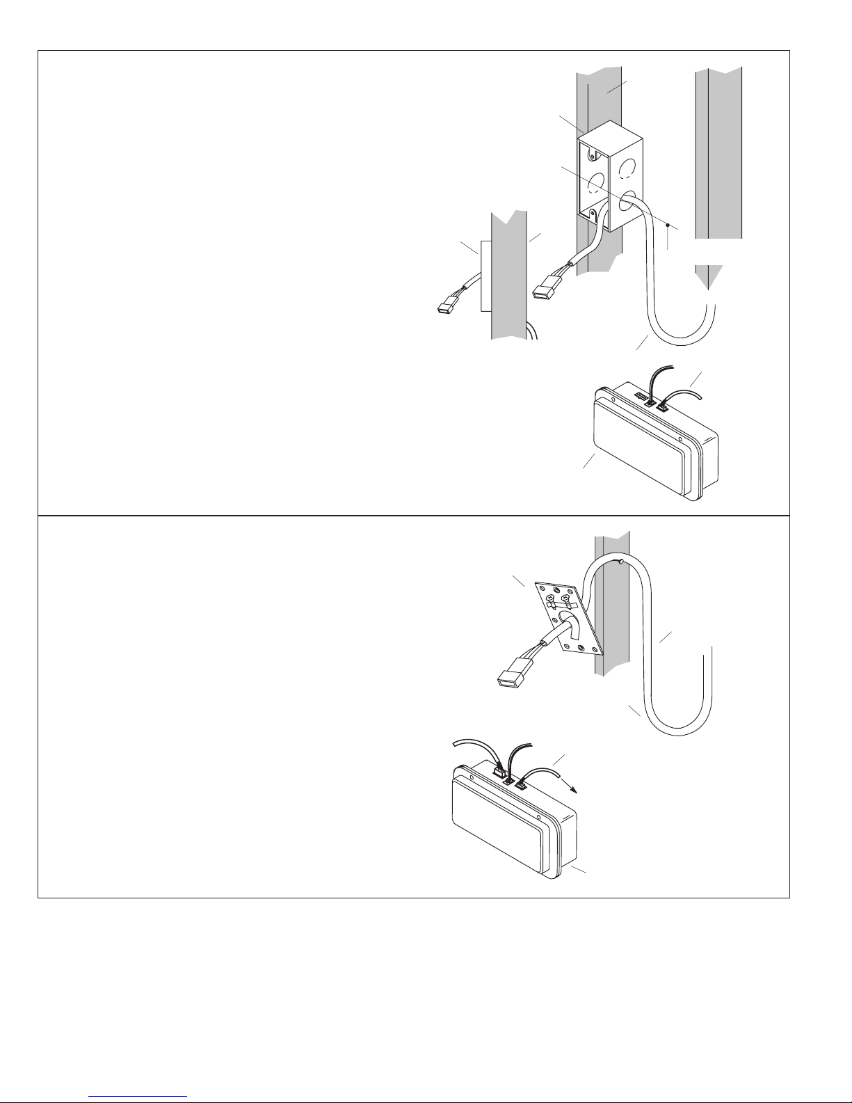
B. INSTALL CABLE USING OUTLET BOX
Stud
NOTE: If the desired keypad location does not permit you
to secure the provided outlet box directly to a stud, you can
route the control cable directly through the wall material
without using an outlet box. Proceed to Step C. to install
the keypad without an outlet box.
Plug the control cable into the right jack of the control box.
Position the supplied outlet box inside the enclosure at the
chosen control mounting location so the metal plate (not
shown) will be flush with the finished wall or slightly
recessed when installed. Install the outlet box so the 10’
control cable is within reach of the control box. Do not
stretch or pull on the control cable. Install the outlet box
58” to 60” up from the floor of the footbath.
Secure the outlet box to the nearest stud.
Route the control cable from the control box to the outlet
box, and insert the loose connector into the knockout hole
in the outlet box. Create a drip loop in the cable.
NO
TE: National Electrical Code requires that you
permanently separate the high- and low-voltage cables.
Outlet
Box
Outlet Box
SIDE VIEW
Control Box
Stud
Drip Loop
58” To 60”
From Floor
Control
Cable
C. INST ALL CABLE WITHOUT OUTLET BOX
Plug the control cable into the right jack of the control box.
Route the control cable directly through the large hole in
the center of the metal plate. Temporarily tape together
the control cable and the metal plate. Also tape the two
screws to the metal plate to prevent them from becoming
lost. Create a drip loop in the cable to prevent water from
following the cable down to the control box.
Temporarily secure the control cable and metal plate to
the stud nearest your chosen keypad mounting location.
Position the metal plate 58” to 60” up from the floor of the
footbath.
Leave the control cable and metal plate attached here
until the finished wall is constructed. At that time, the metal
plate will be permanently attached flush to the outside
surface of the finished wall with two screws. The control
cable will then be secured to the metal plate with a cable
tie looped between the large and small center holes in the
metal plate.
NO
TE: National Electrical Code requires that you
permanently separate the high- and low-voltage cables.
Metal Plate
Control Cable
Drip Loop
Control Cable
To Metal Plate
Control Box
116290-2-AB
8
Kohler Co., Kohler WI U.S.A.
Page 9
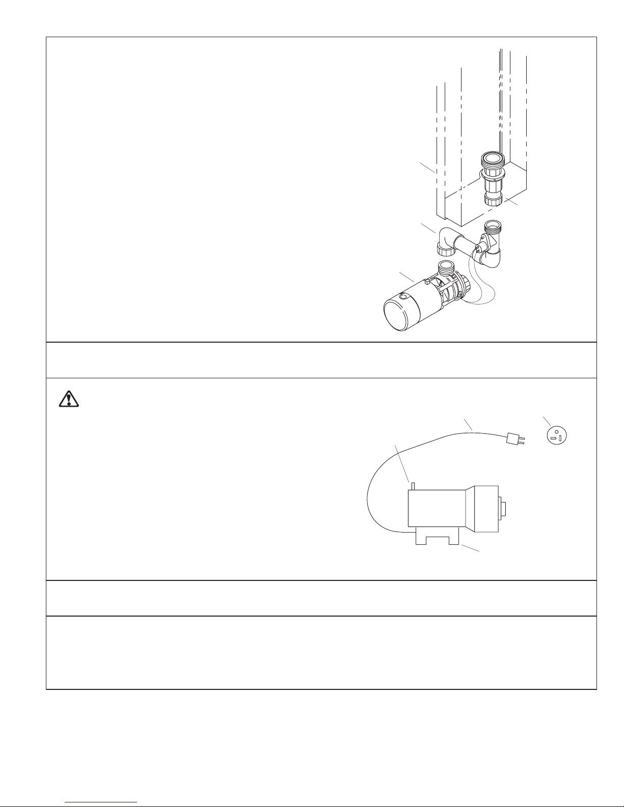
D. CONNECT VARIABLE FLOW V AL VE
ASSEMBL Y TO PUMP
Loosen the variable flow valve assembly by unthreading
the union nut. Reposition the variable flow valve assembly
so the outlet union lines up with the mounting frame union
nut. Securely handtighten the union nut. Be sure the union
O-ring is in place. Do not apply sealant to the union.
Handtighten the mounting frame union nut to the variable
flow valve union. Be sure the union O-ring is in place. Do
not apply sealant to the union.
Mounting
Frame
7. ELECTRICAL CONNECTIONS
WARNING: Risk of electrical shock. To reduce
the risk of electric shock, connect only to a properly
grounded, grounding-type receptacle, protected
by a Ground-Fault Circuit-Interrupter (GFCI). Do
not remove the plug’s grounding pin. Do not use a
grounding adapter.
The Kohler BodySpa is equipped with a cord and plug.
All wiring of the pump and control has been completed
at the factory. A licensed electrician must install a
GFCI-protected, 120 V, 20 A, grounded outlet. The
BodySpa may then be plugged into this outlet. No other
load should be on this circuit. Locate the outlet behind
the BodySpa, and within 24” of the pump.
Variable Flow
V alve Assembly
Pump
Bonding
(Earthing)
Lug*
Plug-in
Cord
Pump
Mounting
Frame
Union Nut
BACK VIEW
20 A
Receptacle
* For bonding in accordance with national and local
codes.
8. INSPECT CONNECTIONS
Check all electrical connections.
Open the hot and cold water valves, and check all supply
connections for leaks. Fill the footbath to the overflow,
and check the overflow and drain connections for leaks.
Kohler Co., Kohler WI U.S.A.
Control Box
9
116290-2-AB
Page 10

9. DOOR ENCLOSURE PREPARATION
The BodySpa door enclosure is designed to fit only the
BodySpa footbath. Proper door enclosure assembly
depends upon installation of the footbath against square
and plumb studding. The stud supports must be within
3/8” of plumb.
IMPORTANT: Leave studs exposed. The door
enclosure wall jambs must be secured directly to the
double stud wall frame to achieve proper support of the
door enclosure. Expanding wall anchors in a hollow wall
will not provide adequate support for the door enclosure
assembly . Under no circumstances install the finished
wall material until instructed.
NO
TE: The door enclosure components are identified
with removable labels. Refer to these labels to correctly
identify and install the enclosure components.
10. INSTALL THE ENCLOSURE
A. INSTALL THE W ALL JAMBS
Remove the wall jamb kit from the carton, and remove the
wall jambs. Leave the wall jamb protective tape in place.
Do not remove any other components from the carton at
this time.
Install one of the wall jambs by setting it against the
footbath locating pin, as shown. The wall jambs are not
interchangeable.
Use a level, and adjust the wall jamb to be exactly plumb.
Secure the wall jamb to the double stud framing and
furring strips with four 2” stainless steel flathead screws
(provided).
Repeat for the other wall jamb.
Wall
Jamb
Level
2” Stainless
Steel Flathead
Screw
116290-2-AB
10
Footbath Locating Pin
Kohler Co., Kohler WI U.S.A.
Page 11

CAUTION: Risk of property damage and
concealed leakage. The application of silicone
sealant as instructed is essential to ensure a
correct, watertight installation. Follow all sealing
instructions exactly.
Apply a continuous bead of silicone sealant to the inside
of the wall jamb where it contacts the footbath, as shown.
Repeat for the other wall jamb.
TOP VIEW
INSIDE OF
WALL JAMB
Apply
Silicone
Sealant
B. INSTALL THE CENTER EXP ANDERS
Remove and discard the thread caps from the center
expanders. Fit a center expander into one of the wall
jambs, as shown. The projection on the center expander
fits behind the footbath locating pin, as shown. Push the
bottom of the center expander all the way into the wall
jamb. Plumb the center expander by turning the top
buttonhead screw in or out with the balldriver tool.
Check for plumb with a level. When the center expander
is plumb, turn in the center buttonhead screw until you feel
it just contact the wall jamb. Recheck for plumb, then
secure the center expander to the wall jamb with three
3-1/2” stainless steel flathead screws (provided).
Remove the protective tape from the inside of the wall
jamb. Do not remove the tape from the outside of the wall
jamb at this time.
Repeat for the other center expander.
Complete the finished wall according to the following
instructions.
Locating Pin
Center
Expander
TOP VIEW
Center Expander
3-1/2”
Stainless Steel
Flathead Screw
Wall
Jamb
Top
Buttonhead
Screw
Wall
Jamb
Kohler Co., Kohler WI U.S.A.
11
Footbath
Locating
Pin
116290-2-AB
Page 12

IMPORTANT! You have now completed the initial roughing-in phase of the
BodySpa installation. Keep these instructions with the door enclosure so they
are readily available following the completion of finished wall construction.
C. COMPLETE THE FINISHED WALL
CAUTION: Risk of product damage. Use
extreme care to avoid scratching the wall jambs.
NO
TE: The total finished wall thickness, including furring
strips, cement board, and finished wall material, must not
be more than 1-1/2”.
Install cement board no more than 1/4” above the top of
the footbath rim.
Apply a bead of silicone sealant to the seam between the
cement board and the footbath.
Install the finished wall material.
Bead of
Silicone
Sealant
Between
Cement
Board and
Footbath
1/4”
MAX.
For keypad installations that do not use the supplied outlet
box, refer to Step C. on Page 8 for installation
requirements.
Use a sharp utility knife to carefully score and remove the
protective tape from the wall jambs and center expanders.
Finished
Wall
1/2” Cement
Board
Galvanized
Nail Or
Screw
1-1/2”
MAX.
Furring Strip
TOP VIEW
116290-2-AB
12
Kohler Co., Kohler WI U.S.A.
Page 13

D. INSTALL THE HEADER
With assistance, lift the header between the center
expanders so the bottom dimpled holes in the header
brackets fit over the adjustment screws. Check the
alignment of the side holes in both header brackets to the
adjustment screw heads. If the holes do not line up with
the adjustment screw heads, loosen the header
bracket(s) setscrews, and realign the header bracket(s)
until the holes line up with the adjustment screw heads.
Retighten the header bracket setscrews.
Add a 1/4” flat washer to each of the two buttonhead
screws. Thread a buttonhead screw and washer through
each header bracket top hole, and into the center
expander. Securely tighten each buttonhead screw with
the supplied hex socket tool and a ratchet wrench.
1/4-20 x 5/8”
Buttonhead
Screw
1/4” Washer
Header
Header
Bracket
Setscrew
Adjustment
Screw
Center Expander
Measure the header height from the footbath rim at the
end, and again in the center, as shown. Compare the
distance. The header should be 1/4” higher at the center.
The combined weight of the door panels will pull the
header down until it is level or close to level.
Adjust the level of the header by first loosening the
buttonhead screw securing the header to the center
expander. Now back out the adjustment screw one or two
turns. Retighten the buttonhead screw with the hex socket
tool and ratchet. This will cause the header to pivot slightly
upward.
Alternate this procedure on both ends of the header, and
again measure the header height at the end and the
center. Repeat until the header is 1/4” higher at the center .
Be sure to securely tighten the buttonhead screws with
the hex socket tool and ratchet when the adjustments are
complete.
Very Important! The header must be 1/4” higher at the
center before proceeding. The center of the header must
not sag downward or the door panels will not operate
correctly.
End
Tape
Measure
Buttonhead Screw
Center
Header
Kohler Co., Kohler WI U.S.A.
13
Adjustment Screw
116290-2-AB
Page 14

E. HANG THE SIDE DOOR P ANELS
Fit a bushing over each outside track roller in the header.
Header
With assistance, lift one of the side doors into place, and
fit an outside track roller into each of the two holes in the
glass.
Insert another bushing into each hole from the opposite
side of the glass. Thread a roller nut into each roller.
Carefully handtighten each roller nut. Do not tighten with
a wrench at this time, and do not try to level the door yet.
Repeat for the other side door.
F . HANG THE CENTER DOOR P ANEL
Fit a bushing over each inside track roller in the header.
With assistance, lift the center door panel into place, and
fit an inside track roller into each of the two holes in the
glass.
Insert another bushing into each hole from the opposite
side of the glass. Thread a roller nut into each roller.
Carefully handtighten each roller nut. Do not tighten with
a wrench at this time, and do not try to level the door
panels yet.
Bushing
Roller
Side Door
Panel
Roller Nut
Bushing
Header
Bushing
Roller
Center Door
Panel
Bushing
Roller Nut
116290-2-AB
14
Kohler Co., Kohler WI U.S.A.
Page 15

G. ADJUST HEADER HEIGHT
Slide all three door panels to the center, and measure and
record the distance from the footbath curb to the header
at three locations:
the left corner, along the wall jamb;
the right corner, along the wall jamb;
the center, along the center door panel.
If the three measurements are the same, no header
adjustment is required. Occasionally, the center height
measurement will be different from the corner measurements. In these cases, adjust the header in this manner:
Loosen one of the buttonhead screws about two complete
turns. Next loosen the corresponding adjustment screw a
complete turn or two, and retighten the buttonhead screw.
Check the center height measurement. Repeat this
procedure until half the needed height correction is
obtained.
Repeat this adjustment procedure on the other end of the
header.
NO
TE: Remember that the center height measurement
must be the same as the corner measurements when the
doors are in the center.
Header
Buttonhead Screw
Adjustment Screw
H. INST ALL THE CENTER JAMB ASSEMBLIES
Press a center jamb assembly against the center
expander. Secure with six #8 x 1” panhead screws. Do not
overtighten.
Repeat for the other side.
Header Bracket
Center
Expander
Center Jamb
#8 x 1” Panhead
Screws
Center Jamb
TOP VIEW
Kohler Co., Kohler WI U.S.A.
15
116290-2-AB
Page 16

I. INST ALL THE SIDE JAMB SEALS
Lubricate one of the side jamb seals with glass cleaner.
Starting at the bottom of one of the center jambs, insert the
side jamb seal into the center jamb groove. Trim the top
of the seal as needed.
Repeat for the other side jamb seal.
J. ADJUST THE SIDE DOOR P ANELS
Use the wrench provided to loosen a roller nut on one of
the side door assemblies. Adjust the height of the door
panel by turning the cam roller with the wrench so the
corner of the bottom deflector just rests on the acrylic
surface of the footbath. Tighten the roller nut.
Side Jamb Seal
Footbath
Roller Nut
Side
Jamb
Seal
Center Jamb
TOP VIEW
Now loosen the other roller nut, and adjust the side door
height by turning the cam roller with the wrench so the side
door edge lines up perfectly with the side jamb seal.
Tighten the roller nut.
Check that the bottom deflector just rests on the acrylic
surface of the footbath across the entire deflector length.
Adjust the side door cam roller as needed to ensure:
proper contact of the bottom deflector with the acrylic
surface of the footbath,
parallel alignment between the side door handle edge
and the side jamb seal.
Repeat for the other side door assembly.
Side Door
Assembly
Bottom
Deflector
Side Door Assembly
Side Jamb
Seal
Center
Door Panel
Footbath
116290-2-AB
16
Kohler Co., Kohler WI U.S.A.
Page 17

K. ADJUST THE CENTER DOOR P ANEL
Check if the center door panel hangs parallel with both
side door assemblies. Also check that the bottom
deflector just makes contact with the acrylic surface of the
footbath.
Loosen one or both roller nuts, and adjust the center door
panel by turning the cam roller with the wrench to obtain
proper fit. Tighten any loose roller nuts.
Center Door Panel
Bottom Deflector
L. INST ALL THE BACKSTOP
Choose a backstop and cover to match the color of the
door frame.
Insert the well nut into the pre-drilled hole in the center of
the footbath curb.
Attach the backstop to the footbath curb by securely
threading a #10 x 1” panhead screw into the well nut. Do
not overtighten.
Apply silicone sealant to the backstop cap, then press it
onto the backstop.
M. INST ALL THE DOOR HANDLES
Fit the gasket over the groove in the side of the door panel.
Loosen the six handle clamp screws. Press the handle
over the gasket so the clamp and screws are on the inside.
Thread in one or two screws to temporarily hold the
handle in place. Note that the handle protrusion fits into
the groove in the glass panel. Slide the handle up or down
so the bumper flat rests on the footbath curb. Carefully
tighten all six screws. Use care to avoid stripping the
screws.
Repeat this procedure for the other handle.
Backstop
Cap
Handle
#10 x 1” Panhead Screw
Backstop
Well Nut
Apply
Sealant
Curb
Gasket
Handle
Clamp
Screws
Kohler Co., Kohler WI U.S.A.
17
Bumper
Flat
Handle
Clamp
Side Door Panel
116290-2-AB
Page 18

N. ADJUST THE STOP BLOCKS
NOTE: This step is critical to prevent the side door panels
from accidentally slamming against one another.
With the doors all closed, open the left side door. Slide the
loose stop block up against the exposed center door roller.
Close the left side door so it rests against the side jamb
seal. Slowly open the right side door until it nearly touches
the left side door. A 1/4” gap between the side door panel
edges is sufficient.
Open the left side door to expose the stop block. Carefully
secure the stop block in place by tightening the stop block
setscrew.
Repeat this procedure for the other stop block.
O. APPL Y SEALANT
Door seals are an integral part of this door. However,
sealing with a quality clear silicone sealant is necessary
to ensure a properly functioning, watertight unit.
The required sealing procedure follows:
Mask both edges of joint to be sealed, maintaining a
joint width of 1/8” to 3/16”.
Apply a uniform bead of sealant. Smooth the bead with
your finger.
Remove the tape from the sealed joints immediately
after smoothing the bead.
Repeat for all areas to be sealed.
Stop Block
Stop Block
Setscrew
Header
INSIDE UNIT
Roller
Center Door Panel
Apply
Sealant
Inside
Track
Wall
Jamb
Very Important! Apply silicone sealant to the outside
bottom edge of the center jambs and wall jambs only . On
the inside, apply a bead of silicone sealant vertically along
the seam between the wall jambs and finished wall
surface. Do not apply sealant to the inside bottom of the
center jambs and wall jambs.
1/8” to 3/16”
Joint Width
Center
Jamb
Masking Tape
Footbath
Apply
Sealant
IMPORTANT! You have now completed the door enclosure installation phase
of the BodySpa installation. Keep these instructions with the tower so they are
readily available for the final installation procedures.
116290-2-AB
18
Kohler Co., Kohler WI U.S.A.
Page 19

11. INSTALL THE TOWER
NOTE: Before you proceed, be sure the door enclosure
installation is complete and the finished wall materials
have been installed.
Line up the pin at the bottom left corner of the tower with
the hole in the mounting frame, and set the pin in the hole.
Now line up the hole at the top left corner of the tower with
the slotted hole in the mounting frame, and thread a 3/8”
bolt through the mounting frame and into the tower.
Tighten the bolt securely.
Tower
Pin
Mounting
Frame
Hole
BOTTOM LEFT CORNER VIEW
Bolt
Tower
TOP LEFT CORNER VIEW
Mounting Frame
Slotted Hole
Kohler Co., Kohler WI U.S.A.
19
116290-2-AB
Page 20

Route the tower cable into the large hole in the back of the
mounting frame. Snap the modular plug on the end of the
tower cable into the left jack of the control box. Install the
large strain relief bushing over the tower cable, and insert
it into the large mounting frame hole.
TE: National Electrical Code requires that you
NO
permanently separate the high- and low-voltage cables.
Large
Strain
Relief
Tower Cable
Mounting Frame
Control Box
Route the waterfall light wires through the small hole in the
back of the mounting frame. With the pump access panel
removed, connect the waterfall light wire connectors to
the transformer terminals – white to white; black to black.
Install the small strain relief bushing over the waterfall light
wires, and insert it into the small mounting frame hole.
From
Waterfall
Light
Small
Strain
Relief
Bushing
Mounting Frame
Small
Hole
Transformer
Snap
To Control Box
116290-2-AB
20
Kohler Co., Kohler WI U.S.A.
Page 21

Securely handtighten the tower union nut to the mounting
frame union. Be sure the union O-ring is in place.
Tower
Union
Nut
Mounting
Frame
Union
Carefully pivot the tower closed. Line up the holes at the
top and bottom right corners of the tower with the slotted
holes in the mounting frame. Thread a 3/8” bolt through
the mounting frame and into the tower at the top and
bottom. Tighten the bolts securely , but do not overtighten.
Water testing and inspection is required later. You may
want to only install and handtighten one of the required
bolts at this time. Both bolts will need to be securely
tightened later.
12. COMPLETE INSTALLATION
Bolt
Bolt
To Improve Clarity, the Door
Enclosure is not Shown.
A. INST ALL HANDLES AND SPOUT
CAUTION: Risk of property damage. The valve,
spout, and other plumbing fittings must be
adequately sealed to prevent water leakage
behind the finished wall.
Install the faucet handles and spout according to the
manufacturer’s instructions. Seal around the plumbing
fittings.
Kohler Co., Kohler WI U.S.A.
21
116290-2-AB
Page 22

B. INST ALL KEYP AD
CAUTION: Risk of personal injury or product
damage. The metal plate must be installed flush
with the finished wall or slightly recessed (maximum
1/4”).
Feed the control cable through the hole in the metal plate.
Use two flathead screws to attach the metal plate to the
outlet box or finished wall material so the metal plate is
flush with the finished wall or slightly recessed
(maximum 1/4”).
Finished
Wall
Keypad
Snap the keypad modular plug into the keypad cable jack.
Apply silicone sealant to each of the keypad screw holes,
and secure the keypad to the metal plate with four
panhead screws.
CAUTION: Risk of personal injury or product
damage. Prevent water damage to the keypad by
applying silicone sealant as instructed.
IMPORTANT: Apply a continuous bead of clear silicone
sealant to the cover plate sealant grooves, as shown.
Slip the center pin at the top of the cover plate up through
the hole in the keypad. Secure the cover plate to the
keypad with a panhead screw.
Panhead
Screw
Metal
Plate
Flathead
Screw
Snap Plugs
Apply Silicone
Sealant
Top
Cap
Apply Silicone
Sealant
Center
Pin
Select the bottom cap – it contains the word “KOHLER”,
and has a small notched area along the contact surface
edge.
IMPORTANT: Apply silicone sealant to the bottom cap
along the back surface and also to the edge that contacts
the cover plate. Align the bottom cap holes with the cover
plate pins, and push the cap into place. Repeat for the top
cap.
Remove any excess sealant.
116290-2-AB
Apply Silicone
Sealant
22
Apply Silicone
Sealant to
Sealant
Grooves
Keypad
Cover Plate
Panhead
Screw
Bottom
Cap
Kohler Co., Kohler WI U.S.A.
Page 23

13. INSTALL THE SEAT
Remove the thumb screw, stainless steel washer, and
rubber washer from the seat.
Slide the seat onto the bracket as shown.
Install the stainless steel washer, then the rubber washer
onto the thumb screw. Insert the thumb screw through the
bracket’s center slot and into the threaded hole in the seat
channel. Securely handtighten the thumb screw.
Thumb Screw
Rubber Washer
Stainless Steel
Washer
14. WATER TEST FOOTBATH AND TOWER
Make sure all PVC union connections are securely hand
tightened.
Fill the BodySpa to the bottom of the drain overflow.
Remove the motor/control access panel. Run the
BodySpa for 5 minutes and check the visible harness
(piping) and union connections for leaks.
Turn off the BodySpa.
Open the tower, and inspect all piping connections for
leaks.
Seat
Bracket
Close the tower. Thread in and securely tighten two 3/8”
bolts. Do not overtighten.
For additional information on BodySpa operation, see
Start-Up BodySpa instructions on Page 24.
15. CLEAN-UP AFTER INSTALLATION
When cleaning up after installation, do not use abrasive
cleansers as they may scratch and dull the footbath
surface. Use warm water and a liquid detergent to clean
the surface.
Kohler Co., Kohler WI U.S.A.
Stubborn stains, paint, or tar can be removed with
turpentine or paint thinner. Do not allow cleaners
containing petroleum distillates to remain in contact
with footbath surfaces for long periods of time.
Plaster can be removed by scraping with a wood edge. Do
not use metal scrapers, wire brushes, or other metal tools.
A powder-type detergent may be used on a damp cloth to
provide mild abrasive action to the residual plaster.
23
116290-2-AB
Page 24

16. CONFIRM PROPER OPERATION
A. ST ART-UP BODYSP A
Please perform the following so the owner can safely
receive the benefits of their BodySpa.
Water temperature in the footbath should not exceed
104F (40C).
1. Fill the footbath to the bottom of the drain overflow.
NO
TE: Refer to the chart at right for the proper operating
sequence.
2. Turn on the BodySpa by pressing the Power button
on the keypad. Water will flow from the Waterfall at
the lowest flow setting, and the Waterfall light will turn
on. The light will remain on throughout the operating
sequence.
3. Use the ↑ and ↓ arrows to vary the water force.
4. Press the Body Jet button. Water will flow from Body
Jet arrays 2, 3, and 4 at low speed. Water will stop
flowing from the Waterfall.
5. This BodySpa features five pairs of Body Jets. Press
any combination of buttons 1 through 5 to choose the
desired water distribution.
6. Use the ↑ and ↓ arrows to vary the water force.
7. A built-in timer automatically stops the motor after 20
minutes of operation.
TO METHOD OBSERVE
Turn on the
BodySpa.
Select desired
BodySpa
features.
Increase water
force, press the ↑
button.
Decrease water
force, press the ↓
button.
Shut off the
BodySpa.
Restart
BodySpa
after the
20 minute
cycle is
complete.
116290-2-AB
24
Kohler Co., Kohler WI U.S.A.
Page 25

B. TROUBLESHOOTING
g
not functioning
not function
Here’s what you need to do if you require service: First review the installation instructions to ensure correct installation.
If you are unable to correct the problem, call our Customer Service Department for direct help. Dial 1-800-4-KOHLER.
SYMPTOMS PROBABLE CAUSES CORRECTIVE ACTION
1. BodySpa does
not start/stop.
A. No power to pump/control. A. Set/Reset GFCI breaker; check wiring to
pump/receptacle.
B. Harness is blocked. B. Remove blockage.
2. Water flow
surges.
3. Motor starts, all
Body Jets are
not functionin
4. Motor starts,
waterfall does
not function.
.
5. Water increases
when ↓ keypad
button is
pressed –
decreases when
↑ button is
pressed.
6. Waterfall light
does not work.
C. Keypad disconnected from pump/control
C. Reconnect keypad.
box.
D. Faulty keypad. D. Replace keypad.
E. Faulty circuit board. E. Replace circuit board inside control box.
F. Faulty motor/pump assembly. F. Replace motor/pump assembly.
G. Not enough water in footbath. G. Fill footbath to drain overflow.
A. Not enough water in footbath. A. Fill footbath to drain overflow.
B. Suction blocked. B. Remove obstruction.
C. Harness is blocked. C. Remove blockage.
A. Jet is blocked. A. Remove blockage.
B. Faulty keypad. B. Replace keypad.
.
.
C. Butterfly valve wiring loose or damaged,
or butterfly valve is faulty.
C. Identify source of fault and correct, or
replace faulty butterfly valve.
A. Waterfall is blocked. A. Remove blockage.
B. Faulty keypad. B. Replace keypad.
C. Butterfly valve wiring loose/damaged –
butterfly valve is faulty.
C. Identify source of fault and correct, or
replace faulty butterfly valve.
A. Variable flow valve wiring error. A. Reverse variable flow valve wire
connections.
A. Light bulb is burned out. A. Replace light bulb.
B. Loose or damaged wiring. B. Identify source of fault and correct.
7. BodySpa stops
automatically
before 18
minutes.
8. BodySpa does
A. GFCI trips. A. Identify source of fault and correct.
B. Motor overheated and protection device
activated.
A. Faulty timer mechanism. A. Replace timer board inside pump/motor.
not
automatically
stop after 22
B. Wiring error. B. Refer to dealer.
minutes.
9. Noisy operation. A. Pump strap has not been cut. A. Cut strap with tin snips.
B. Not enough water in footbath. B. Fill footbath to drain overflow.
Kohler Co., Kohler WI U.S.A.
25
B. Check for blockage at motor vents.
Remove blockage and allow motor to
cool.
Check for suction/harness blockage.
Remove blockage and allow motor to
cool.
116290-2-AB
Page 26

116290-2-AB
26
Kohler Co., Kohler WI U.S.A.
Page 27

Kohler Co., Kohler WI U.S.A.
27
116290-2-AB
Page 28

116290-2-AB
28
Kohler Co., Kohler WI U.S.A.
 Loading...