

Page 1
COMMAND PRO CS
4-12.75 HP
HORIZONTAL CRANKSHAFT
SERVICE MANUAL
Page 2

Contents
Section 1. Safety and General Information .............................................................................
1
Section 2. T ools & Aids ............................................................................................................
Section 3. T roubleshooting .....................................................................................................
Section 4. Air Cleaner and Air Intake System .........................................................................
Section 5. Fuel System and Governor ....................................................................................
Section 6. Lubrication System ................................................................................................
Section 7. Retractable Starter..................................................................................................
Section 8. Electrical System and Components......................................................................
2
3
4
5
6
7
8
Section 9. Disassembly............................................................................................................
Section 10. Internal Components............................................................................................
Section 11. Reassembly...........................................................................................................
9
10
11
Page 3
Section 1
Safety and General Information
Safety and General Information
Safety Precautions
To ensure safe operations please read the following statements and understand their meaning.
Also refer to your equipment owner's manual for other important safety information. This manual
contains safety precautions which are explained below. Please read carefully.
WARNING
Warning is used to indicate the presence of a hazard that can cause severe personal injury,
death, or substantial property damage if the warning is ignored.
CAUTION
Caution is used to indicate the presence of a hazard that will or can cause minor personal injury
or property damage if the caution is ignored.
NOTE
Note is used to notify people of installation, operation, or maintenance information that is
important but not hazard-related.
Section 1
1
For Y our Safety!
These precautions should be followed at all times. Failure to follow these precautions could result in injury
to yourself and others.
WARNING
Accidental Starts can cause severe
injury or death.
Disconnect and ground spark plug
lead before servicing.
Accidental St arts!
Disabling engine. Accidental starting
can cause severe injury or death. Before
working on the engine or equipment,
disable the engine as follows: 1)
Disconnect the spark plug lead(s). 2)
Disconnect negative (-) battery cable
from battery.
WARNING
Rotating Parts can cause severe
injury.
Stay away while engine is in
operation.
Rotating Part s!
Keep hands, feet, hair, and clothing
away from all moving parts to prevent
injury. Never operate the engine with
covers, shrouds, or guards removed.
WARNING
Hot Parts can cause severe burns.
Do not touch engine while operating
or just after stopping.
Hot Parts!
Engine components can get extremely
hot from operation. To prevent severe
burns, do not touch these areas while
the engine is running—or immediately
after it is turned off. Never operate the
engine with heat shields or guards
removed.
1.1
Page 4

Section 1
Safety and General Information
WARNING
Explosive Fuel can cause fires and
severe burns.
Do not fill the fuel tank while the
engine is hot or running.
Explosive Fuel!
Gasoline is extremely flammable and
its vapors can explode if ignited. Store
gasoline only in approved containers,
in well ventilated, unoccupied
buildings, away from sparks or flames.
Do not fill the fuel tank while the
engine is hot or running, since spilled
fuel could ignite if it comes in contact
with hot parts or sparks from ignition.
Do not start the engine near spilled
fuel. Never use gasoline as a cleaning
agent.
WARNING
WARNING
Carbon Monoxide can cause severe
nausea, fainting or death.
Avoid inhaling exhaust fumes, and
never run the engine in a closed
building or confined area.
Lethal Exhaust Gases!
Engine exhaust gases contain
poisonous carbon monoxide. Carbon
monoxide is odorless, colorless, and can
cause death if inhaled. Avoid inhaling
exhaust fumes, and never run the
engine in a closed building or confined
area.
WARNING
Uncoiling Spring can cause severe
injury.
Wear safety goggles or face protection
when servicing retractable starter.
WARNING
Explosive Gas can cause fires and
severe acid burns.
Charge battery only in a well
ventilated area. Keep sources of
ignition away.
Explosive Gas!
Batteries produce explosive hydrogen
gas while being charged. To prevent a
fire or explosion, charge batteries only
in well ventilated areas. Keep sparks,
open flames, and other sources of
ignition away from the battery at all
times. Keep batteries out of the reach of
children. Remove all jewelry when
servicing batteries.
Before disconnecting the negative (-)
ground cable, make sure all switches
are OFF. If ON, a spark will occur at
the ground cable terminal which could
cause an explosion if hydrogen gas or
gasoline vapors are present.
Cleaning Solvents can cause severe
injury or death.
Use only in well ventilated areas
away from ignition sources.
Flammable Solvents!
Carburetor cleaners and solvents are
extremely flammable. Keep sparks,
flames, and other sources of ignition
away from the area. Follow the cleaner
manufacturer’s warnings and
instructions on its proper and safe use.
Never use gasoline as a cleaning agent.
Spring Under T ension!
Retractable starters contain a powerful,
recoil spring that is under tension.
Always wear safety goggles when
servicing retractable starters and
carefully follow instructions in the
"Retractable Starter" Section 7 for
relieving spring tension.
CAUTION
Electrical Shock can cause injury.
Do not touch wires while engine is
running.
Electrical Shock!
Never touch electrical wires or
components while the engine is
running. They can be sources of
electrical shock.
1.2
Page 5

Engine Identification Numbers
When ordering parts, or in any communication
involving an engine, always give the Model,
Specification, and Serial Numbers of the engine.
The engine identification numbers appear on a decal
(or decals) affixed to the engine shrouding. See Figure
1-1. An explanation of these numbers is shown in
Figure 1-2.
Model Designation
Model CS6ST for example: C designates Command
engine, S designates slanted cylinder configuration,
and 6 designates horsepower. A suffix letter
designates a specific version as follows:
Section 1
Safety and General Information
1
Identification Decal
Figure 1-1. Engine Identification Decal Location.
A. Model No.
Command Engine
Slanted Cylinder
Horsepower
4 = 4 HP
6 = 6 HP
8.5 = 8.5 HP
10 = 10 HP
12 = 12 HP
B. Spec. No.
Engine Model Code
Code Model
90 CS4
91 CS6
92 CS8.5# 300 cc
93 CS10
94 CS12
95 CS8.5# 250 cc
C. Serial No.
Year Manufactured Code
Code Year
28 1998
29 1999
30 2000
31 2001
32 2002
C S 6 ST
911509
28 23701265
Code Year
33 2003
34 2004
35 2005
36 2006
37 2007
Suffix Designates
T Retractable S tart
S Electric S tart
G Tapered Crankshaft
P Threaded Crankshaft
R Gear Reduction (2:1 or 6:1)
IMPORTANT ENGINE INFORMATION
THIS ENGINE MEETS U.S. EPA PHASE II, 2002-
2005 CALIFORNIA AND EC STAGE II (SN:4)
Variation of
Basic Engine
EMISSION CONTROL REGS FOR SI SMALL OFF–
ROAD ENGINES
FAMILY
TYPE APP
MODEL NO. CS6ST
SPEC. NO. 911509
DISPL. (CC)
SERIAL NO. 2823701265
OEM PROD. NO.
EMISSION COMPLIANCE PERIOD:
EPA: CATEGORY A
Factory
Code
CERTIFIED ON: UNLEADED GASOLINE
REFER TO OWNER'S MANUAL FOR SAFETY,
MAINTENANCE SPECS, AND ADJUSTMENTS
1-800-544-2444 www.kohlerengines.com
KOHLER CO. KOHLER, WISCONSIN USA
(REF:_______________ )
A
B
C
N432
Figure 1-2. Explanation of Engine Identification Numbers.
#
NOTE: CS8.5 engines have been produced in two different specification series, 92xxxx and 95xxxx. The design
features of 92xxxx spec. no. engines are identical to CS10 and CS12 engines, and share the same service
procedures. The 95xxxx spec. no. engines incorporate certain design differences from the 92xxxx spec.
no. series. All service and repair information unique to the 95xxxx spec. no. series will be listed and
covered separately.
1.3
Page 6

Section 1
Safety and General Information
Oil Recommendations
Using the proper type and weight of oil in the
crankcase is extremely important, as is checking oil
daily and changing oil regularly. Failure to use the
correct oil or using dirty oil, causes premature engine
wear and failure.
Oil Type
Use high quality detergent oil of API (American
Petroleum Institute) service class SG, SH, SJ or
higher. Select the viscosity based on the air
temperature at the time of operation as shown below.
Synthetic oils should not be used.
Figure 1-3. Viscosity Grades Table.
Fuel Recommendations
WARNING: Explosive Fuel!
Gasoline is extremely flammable and its vapors can explode
if ignited. Store gasoline only in approved containers, in
well ventilated, unoccupied buildings, away from sparks or
flames. Do not fill the fuel tank while the engine is hot or
running, since spilled fuel could ignite if it comes in contact
with hot parts or sparks from ignition. Do not start the
engine near spilled fuel. Never use gasoline as a cleaning
agent.
General Recommendations
Purchase gasoline in small quantities and store in
clean, approved containers. A container with a
capacity of 2 gallons or less with a pouring spout is
recommended. Such a container is easier to handle
and helps eliminate spillage during refueling.
Do not use gasoline left over from the previous
season, to minimize gum deposits in your fuel system
and to insure easy starting.
Do not add oil to the gasoline.
Do not overfill the fuel tank. Leave room for the fuel
to expand.
NOTE: Using other than service class SG, SH, SJ or
higher oil or extending oil change intervals
longer than recommended can cause engine
damage.
A logo or symbol on oil containers identifies the API
service class and SAE viscosity grade. See Figure 1-4.
Figure 1-4. Oil Container Logo.
Refer to Section 6 - ‘‘Lubrication System’’ for detailed
oil check and oil change procedures.
Fuel T yp e
For best results, use only clean, fresh, unleaded
gasoline with a pump sticker octane rating of 87 or
higher. In countries using the Research method, it
should be 90 octane minimum.
Unleaded gasoline is recommended, as it leaves less
combustion chamber deposits. Leaded gasoline may
be used in areas where unleaded is not available and
exhaust emissions are not regulated. Be aware
however, that the cylinder head will require more
frequent service.
Gasoline/Alcohol blends
Gasohol (up to 10% ethyl alcohol, 90% unleaded
gasoline by volume) is approved as a fuel for Kohler
engines. Other gasoline/alcohol blends are not
approved.
Gasoline/Ether blends
Methyl Tertiary Butyl Ether (MTBE) and unleaded
gasoline blends (up to maximum of 15% MTBE by
volume) are approved as a fuel for Kohler engines.
Other gasoline/ether blends are not approved.
1.4
Page 7

Maintenance Instructions
Section 1
Safety and General Information
WARNING: Accident al Starts!
Disabling engine. Accidental starting can cause severe injury or death. Before working on the engine or equipment,
disable the engine as follows: 1) Disconnect the spark plug lead (s). 2) Disconnect negative (-) battery cable from battery.
Maintenance Schedule
These required maintenance procedures should be performed at the frequency stated in the table. They should
also be included as part of any seasonal tune-up.
Daily or Before
Starting Engine
Every 25 Hours
Every 50 Hours
Every 100 Hours
Maintenance RequiredFrequency
• Fill fuel tank.
• Check oil level.
• Check air cleaner for dirty, loose, or damaged parts.
1
• Check air intake and cooling areas, clean as necessary.
• Service precleaner element. Replace if necessary.
• Service solid foam element. Replace if necessary.
1
1
• Change oil.
• Replace air cleaner element.
• Remove cooling shrouds and clean cooling areas.
1
1
• Check all fittings and fasteners.
• Clean fuel shut-off valve filter. Replace if necessary.
1
Refer to:
Section 5
Section 6
Section 4
Section 4
Section 4
Section 4
Section 6
Section 4
Section 4
Section 1
Section 5
• Check muffler screen/spark arrestor. Clean/replace if necessary.
Section 8
Section 11
Section 5
Section 7
Annually or
Every 300 Hours
• Check spark plug condition and gap. Replace if necessary.
• Check and adjust valve clearance when engine is cold.
• Check and adjust idle speed.
• Service starter motor drive, if so equipped.
• Have combustion chamber decarbonized.
2
2
2
2
¹Perform these maintenance procedures more frequently under extremely dusty, dirty conditions.
²Have a Kohler Engine Service Dealer perform this service.
1
Storage
If the engine will be out of service for two months or
more, use the following storage procedure:
1. Clean the exterior surfaces of the engine.
2. Change the oil while the engine is still warm
from operation. See ‘‘Change Oil’’ on page 6.2.
3. The fuel system must be completely emptied, or
the gasoline must be treated with a stabilizer to
prevent deterioration. If you choose to use a
stabilizer, follow the manufacturers
recommendations, and add the correct amount
for the capacity of the fuel system. Fill the fuel
tank with clean, fresh gasoline. Run the engine
for 2-3 minutes to get stabilized fuel into the
carburetor.
To empty the system, run the engine until the
tank and system are empty.
4. Remove the spark plug. Add one tablespoon of
engine oil into the spark plug hole. Install the
plug, but do not connect the plug lead. Crank the
engine two or three revolutions and then turn it
up against compression (when highest pull force
or cranking force is required).
5. Store the engine in a clean, dry place.
1.5
Page 8
Section 1
Safety and General Information
347.00
(13.661)
373.00
(14.685)
66.00
(2.598)
162.00
(6.378)
321.50 (Straight PTO)
(12.657)
143.00
(5.630)
100.00
(3.937)
162.00
(6.378)
30.00
(1.181)
106.00
(4.173)
5/16-24 [qty. 5]
14 mm (.551) deep
384.25
(15.128)
Spark Plug
Oil Fill
Oil Drain Plug
Mounting Face
5.00
(.197)
44.50
(1.752)
37.00
(1.457)
9.0 (.354) dia. [qty. 2]
9.0x14.0 (.354x.551) slot
[qty.2]
80.00
(3.150)
Figure 1-5. T ypical Engine Dimensions CS4 and CS6.
145.25
(5.719)
380.03
(14.962)
Dimensions in millimeters.
Inch equivalents shown in ( ).
1.6
Page 9

452.90
(17.831)
Section 1
Safety and General Information
454.00
(17.874)
445.85
156.68
(6.168)
45°
30°
(17.553)
45°
30°
423.50
(16.673)
70.00
(2.756)
1
Spark Plug
Oil Fill
417.50 (Straight PTO)
(16.437)
187.50
(7.382)
118.34
(4.659)
99.00
(3.898)
205.00
(8.071)
133.50
(5.256)
5/16-24 [qty. 4]
18 mm (.709) deep
3/8-16 [qty. 4]
18 mm (.709) deep
127.00
(5.000) dia.
110.00
(4.331) dia.
90.50
(3.563)
195.50
(7.697)
152.00
(5.984)
165.10 (6.500)
dia.
5/16-24 [qty. 2] 18 mm
(.709) deep
146.08
(5.751) dia.
103.00
(4.055)
298.00
(11.732)
Oil Drain Plug
Mounting Face
16.00
(.630)
37.00
(1.457)
62.00
(2.441)
102.00
(4.016)
11.00 (.433) dia. [qty. 2]
11.00x27 (.433x1.063) slot
[qty. 2]
65.00
(2.559)
Dimensions in millimeters.
Inch equivalents shown in ( ).
Figure 1-6. T ypical Engine Dimensions CS8.5 (spec. 92xxxx), CS10, and CS12 - 12.75.
1.7
Page 10

Section 1
Safety and General Information
431.00
156.00
(6.142)
165.1 (6.50)
(16.968)
110 (4.33)
410.00
(16.142)
428.00
(16.850)
3/8-16 18 mm (.709) deep
[qty. 4]
183.00
(7.205)
94.5
(3.720)
133.50
(5.256)
380.00
(14.961)
146.08 (5.78)
90.50
(3.563)
195.50
(7.697)
103.00
(4.055)
424.00
(16.693)
70.00
(2.756)
5/16-24 18 mm (.709) deep [qty. 2]
5/16-24 18 mm (.709) deep [qty. 4]
11.00x27.00
(.433x1.063)
slotted hole
[qty. 2]
16.00 (.630)
37.00 (1.457)
57.50 (2.264)
C
L
96.00
(3.780)
11 (.433) hole [qty. 2]
59.00 (2.323)
Figure 1-7. T ypical Engine Dimensions CS8.5 (spec. 95xxxx).
1.8
Dimensions in millimeters.
Inch equivalents shown in ( ).
Page 11

Safety and General Information
General Specifications
Power (@ 3600 RPM, exceeds SAE J1940 HP Standards)
CS4 ............................................................................................................. 2.9 kW (4 HP)
CS6 ............................................................................................................. 4.47 kW (6 HP)
CS8.5 (spec. 95xxxx) ................................................................................ 5.40 kW (8.5 HP)
CS8.5 (spec. 92xxxx) ................................................................................ 6.33 kW (8.5 HP)
CS10 ........................................................................................................... 7.45 kW (10 HP)
CS12 ........................................................................................................... 8.95 kW (12 HP)
Hydro 12.75 .............................................................................................. 9.5 kW (12.75 HP)
Peak Torque
CS4 (@ 2000 RPM) .................................................................................... 7.6 N·m (5.6 ft. lb.)
CS6 (@ 2000 RPM) .................................................................................... 10.8 N·m (8 ft. lb.)
CS8.5 (spec. 95xxxx @ 2400 RPM) .......................................................... 16.5 N·m (12.1 ft. lb.)
CS8.5 (spec. 92xxxx @ 2000 RPM) .......................................................... 19.66 N·m (14.5 ft. lb.)
CS10 (@ 2000 RPM).................................................................................. 19.66 N·m (14.5 ft. lb.)
CS12 (spec. 9415xx @ 2000 RPM) ........................................................... 22.6 N·m (16.7 ft. lb.)
CS12 (spec. 9416xx @ 2400 RPM) ........................................................... 24.9 N·m (18.4 ft. lb.)
Hydro 12.75 (@ 2400 RPM) ..................................................................... 30.6 N·m (22.6 ft. lb.)
Bore
CS4 ............................................................................................................. 56.0 mm (2.20 in.)
CS6 ............................................................................................................. 66.0 mm (2.60 in.)
CS8.5 (spec. 95xxxx) ................................................................................ 75.0 mm (2.95 in.)
CS8.5 (spec. 92xxxx) ................................................................................ 78.0 mm (3.07 in.)
CS10 ........................................................................................................... 78.0 mm (3.07 in.)
CS12 ........................................................................................................... 85.0 mm (3.35 in.)
Section 1
1
Stroke
CS4,CS6 ..................................................................................................... 50.0 mm (1.97 in.)
CS8.5 (spec. 95xxxx) ................................................................................ 57.0 mm (2.44 in.)
CS8.5 (spec. 92xxxx) ................................................................................ 63.0 mm (2.48 in.)
CS10-12...................................................................................................... 63.0 mm (2.48 in.)
Displacement
CS4 ............................................................................................................. 123 cc (7.50 cu. in.)
CS6 ............................................................................................................. 171 cc (10.43 cu. in.)
CS8.5 (spec. 95xxxx) ................................................................................ 251 cc (15.30 cu. in.)
CS8.5 (spec. 92xxxx) ................................................................................ 301 cc (18.37 cu. in.)
CS10 ........................................................................................................... 301 cc (18.37 cu. in.)
CS12 ........................................................................................................... 357 cc (21.79 cu. in.)
Compression Ratio
CS4 ............................................................................................................. 8.3:1
CS6 ............................................................................................................. 8.5:1
CS8.5 (spec. 95xxxx) ................................................................................ 8.3:1
CS8.5 (spec. 92xxxx) ................................................................................ 8.1:1
CS10-12...................................................................................................... 8.1:1
Weight (Approx.)
CS4,CS6 ..................................................................................................... 15.4 kg (35 lb.)
CS8.5 (spec. 95xxxx) ................................................................................ 26 kg (57.2 lb.)
CS8.5 (spec. 92xxxx) ................................................................................ 31.9 kg (70.5 lb.)
CS10-12...................................................................................................... 31.9 kg (70.5 lb.)
1.9
Page 12

Section 1
Safety and General Information
General Specifications cont.
Oil Capacity (Approx.)
CS4,CS6 ..................................................................................................... 0.6 L (0.64 U.S. qt.)
CS8.5 (spec. 95xxxx) ................................................................................ 1.0 L (1.1 U.S. qt.)
CS8.5 (spec. 92xxxx) ................................................................................ 1.1 L (1.2 U.S. qt.)
CS10-12...................................................................................................... 1.1 L (1.2 U.S. qt.)
Fuel Tank Capacity
CS4,CS6 ..................................................................................................... 3.9 L (4.1 U.S. qt.)
CS8.5 (spec. 95xxxx) ................................................................................ 6.0 L (6.3 U.S. qt.)
CS8.5 (spec. 92xxxx) ................................................................................ 6.9 L (7.3 U.S. qt.)
CS10-12...................................................................................................... 6.9 L (7.3 U.S. qt.)
Angle of Operation – Maximum (At Full Oil Level) All Directions........ 20°
Air Cleaner
Base Bolt Torque ............................................................................................. 5-8 N·m (44-71 in. lb.)
Base Nut Torque
CS4,CS6 ..................................................................................................... 5-8 N·m (44-71 in. lb.)
CS8.5 (spec. 95xxxx) ................................................................................ 5-8 N·m (44-71 in. lb.)
CS8.5 (spec. 92xxxx) ................................................................................ 10-12 N·m (88-106 in. lb.)
CS10-12...................................................................................................... 10-12 N·m (88-106 in. lb.)
Camshaft
End Play ........................................................................................................... 0.05 mm (0.0020 in.)
Bore I.D. – Max. Wear Limit
CS4,CS6 ..................................................................................................... 14.95 mm (0.583 in.)
CS8.5-12..................................................................................................... 15.95 mm (0.627 in.)
Camshaft Bearing Surface O.D. – Max. Wear Limit
CS4,CS6 ..................................................................................................... 15.05 mm (0.592 in.)
CS8.5-12..................................................................................................... 16.05 mm (0.649 in.)
Carburetor
Fuel Bowl Retaining Screw Torque
CS4,CS6 ..................................................................................................... 7 N·m (62 in. lb.)
CS8.5-12..................................................................................................... 9 N·m (79 in. lb.)
Throttle/Choke Plate Screws Torque ........................................................... 1.5-2.5 N·m (13-22 in. lb.)
Connecting Rod
Connecting Rod Fastener Torque
CS4,CS6 ..................................................................................................... 12 N·m (106 in. lb.)
CS8.5 (spec. 95xxxx) ................................................................................ 12 N·m (106 in. lb.)
CS8.5 (spec. 92xxxx) ................................................................................ 20 N·m (177 in. lb.)
CS10-12...................................................................................................... 20 N·m (177 in. lb.)
Connecting Rod-to-Crankpin Running Clearance
New ........................................................................................................... 0.016/0.046 mm (0.0006/0.0018 in.)
Max. Wear Limit ...................................................................................... 0.1 mm (0.004 in.)
Connecting Rod-to-Crankpin Side Clearance
CS4,CS6 ..................................................................................................... 0.2/0.6 mm (0.008/0.024 in.)
CS8.5 (spec. 95xxxx) ................................................................................ 0.2/0.6 mm (0.008/0.024 in.)
CS8.5 (spec. 92xxxx) ................................................................................ 0.2/0.65 mm (0.0079/0.0256 in.)
CS10-12...................................................................................................... 0.2/0.65 mm (0.0079/0.0256 in.)
1.10
Page 13

Section 1
Safety and General Information
Connecting Rod cont.
Connecting Rod-to-Piston Pin Running Clearance.................................... 0.006/0.025 mm (0.0002/0.0001 in.)
Piston Pin End I.D.
New
CS4,CS6 .............................................................................................. 16.006/16.020 mm (0.6301/0.6307 in.)
CS8.5 (spec. 95xxxx) ......................................................................... 18.006/18.020 mm (0.7089/0.7094 in.)
CS8.5 (spec. 92xxxx) ......................................................................... 20.006/20.020 mm (0.7876/0.7882 in.)
CS10-12 .............................................................................................. 20.006/20.020 mm (0.7876/0.7882 in.)
Max. Wear Limit
CS4,CS6 .............................................................................................. 16.10 mm (0.634 in.)
CS8.5 (95xxxx) ................................................................................... 18.10 mm (0.713 in.)
CS8.5 (92xxxx) ................................................................................... 20.10 mm (0.791 in.)
CS10-12 .............................................................................................. 20.10 mm (0.791 in.)
Connecting Rod Journal End I.D.
New
CS4,CS6 .............................................................................................. 28.000/28.015 mm (1.1023/1.1029 in.)
CS8.5 (spec. 95xxxx) ......................................................................... 32.000/32.015 mm (1.2598/1.2604 in.)
CS8.5 (spec. 92xxxx) ......................................................................... 36.000/36.015 mm (1.4173/1.4179 in.)
CS10-12 .............................................................................................. 36.000/36.015 mm (1.4173/1.4179 in.)
Max. Wear Limit
CS4,CS6 .............................................................................................. 28.115 mm (1.1069 in.)
CS8.5 (95xxxx) ................................................................................... 32.115 mm (1.2644 in.)
CS8.5 (92xxxx) ................................................................................... 36.115 mm (1.4219 in.)
CS10-12 .............................................................................................. 36.115 mm (1.4219 in.)
Crankcase
Closure Plate Fastener Torque
CS4,CS6 ..................................................................................................... 22 N·m (195 in. lb.)
CS8.5-12..................................................................................................... 30 N·m (265 in. lb.)
1
Oil Drain Plugs Torque
CS4,CS6 ..................................................................................................... 17 N·m (150 in. lb.)
CS8.5-12..................................................................................................... 20 N·m (177 in. lb.)
Crankshaft
End Play (Free) ................................................................................................ 0.04 mm (0.0015 in.)
End Play (Threaded Pump Shaft Models Only) ......................................... 0.0/0.2 mm (0.0/0.007 in.)
Flywheel End Main Bearing Journal O.D.
New
CS4,CS6 .............................................................................................. 52 mm (2.047 in.)
CS8.5 (spec. 95xxxx) ......................................................................... 52 mm (2.047 in.)
CS8.5 (spec. 92xxxx) ......................................................................... 80 mm (3.149 in.)
CS10-12 .............................................................................................. 80 mm (3.149 in.)
Max. Wear Limit
CS4,CS6 .............................................................................................. 52.05 mm (2.0492 in.)
CS8.5 (spec. 95xxxx) ......................................................................... 52.05 mm (2.0492 in.)
CS8.5 (spec. 92xxxx) ......................................................................... 80.05 mm (3.1515 in.)
CS10-12 .............................................................................................. 80.05 mm (3.1515 in.)
1.11
Page 14

Section 1
Safety and General Information
Crankshaft cont.
PTO End Main Bearing Journal O.D.
New
CS4,CS6 .............................................................................................. 52 mm (2.047 in.)
CS8.5 (spec. 95xxxx) ......................................................................... 52 mm (2.047 in.)
CS8.5 (spec. 92xxxx) ......................................................................... 72 mm (2.834 in.)
CS10-12 .............................................................................................. 72 mm (2.834 in.)
Max. Wear Limit
CS4,CS6 .............................................................................................. 52.05 mm (2.0492 in.)
CS8.5 (spec. 95xxxx) ......................................................................... 52.05 mm (2.0492 in.)
CS8.5 (spec. 92xxxx) ......................................................................... 72.05 mm (2.836 in.)
CS10-12 .............................................................................................. 72.05 mm (2.836 in.)
Connecting Rod Journal O.D.
New
CS4,CS6 .............................................................................................. 27.969/27.984 mm (1.011/1.017 in.)
CS8.5 (spec. 95xxxx) ......................................................................... 31.969/31.984 mm (1.2586/1.2592 in.)
CS8.5 (spec. 92xxxx) ......................................................................... 35.969/35.984 mm (1.4161/1.4167 in.)
CS10-12 .............................................................................................. 35.969/35.984 mm (1.4161/1.4167 in.)
Max. Wear Limit
CS4,CS6 .............................................................................................. 27.9 mm (1.098 in.)
CS8.5 (spec. 95xxxx) ......................................................................... 31.9 mm (1.2559 in.)
CS8.5 (spec. 92xxxx) ......................................................................... 35.9 mm (1.4134 in.)
CS10-12 .............................................................................................. 35.9 mm (1.4134 in.)
Crankshaft
Runout (Either End) ................................................................................ 0.02 mm (0.0008 in.)
Limit (Either End) .................................................................................... 0.04 mm (0.0016 in.)
Cylinder Bore
Cylinder Bore I.D.
New
CS4 ...................................................................................................... 56.005/56.015 mm (2.2049/2.2053 in.)
CS6 ...................................................................................................... 66.005/66.015 mm (2.5986/2.5990 in.)
CS8.5 (spec. 95xxxx) ......................................................................... 75.005/75.015 mm (2.9530/2.9533 in.)
CS8.5 (spec. 92xxxx) ......................................................................... 78.00/78.02 mm (3.0709/3.0717 in.)
CS10 .................................................................................................... 78.00/78.02 mm (3.0709/3.0717 in.)
CS12 .................................................................................................... 85.00/85.02 mm (3.3465/3.3472 in.)
Max. Wear Limit
CS4 ...................................................................................................... 56.15 mm (2.211 in.)
CS6 ...................................................................................................... 66.15 mm (2.604 in.)
CS8.5 (spec. 95xxxx) ......................................................................... 75.15 mm (2.959 in.)
CS8.5 (spec. 92xxxx) ......................................................................... 78.65 mm (3.096 in.)
CS10 .................................................................................................... 78.65 mm (3.096 in.)
CS12 .................................................................................................... 85.65 mm (3.372 in.)
Max. Out-of-Round ................................................................................. 0.05 mm (0.002 in.)
Cylinder Head
Cylinder Head Bolt Torque
CS4,CS6 ..................................................................................................... 20 N·m (177 in. lb.)
CS8.5-12..................................................................................................... 50 N·m (36 ft. lb.)
Max. Out-of-Flatness ...................................................................................... 0.1 mm (0.004 in.)
Electric Starter
Thru Bolt (Case) Torque
CS8.5-12..................................................................................................... 5.3 N·m (47.7 in. lb.)
1.12
Page 15

Safety and General Information
Electric Starter cont.
Mounting Bolts (To Block) Torque
CS8.5-12..................................................................................................... 16 N·m (141 in. lb.)
Flywheel
Flywheel Retaining Screw Torque
CS4,CS6 ..................................................................................................... 65 N·m (48 ft. lb.)
CS8.5 (spec. 95xxxx) ................................................................................ 65 N·m (48 ft. lb.)
CS8.5 (spec. 92xxxx) ................................................................................ 120 N·m (85 ft. lb.)
CS10-12...................................................................................................... 120 N·m (85 ft. lb.)
Fuel Tank
Fuel Tank Fastener Screws Torque ............................................................... 8-12 N·m (71-106 in. lb.)
Ignition
Spark Plug Type
NGK ........................................................................................................... BPR4ES (13/16 hex)
Champion®............................................................................................... RN14YC (13/16 hex)
Champion®............................................................................................... RC14YC (5/8) hex)
Spark Plug Gap ............................................................................................... 0.76 mm (0.030 in.)
Section 1
1
Spark Plug Torque .......................................................................................... 20 N·m (14.7 ft. lb./177 in. lb.)
Ignition Module Air Gap ............................................................................... 0.4/0.6 mm (0.015/0.023 in.)
Ignition Module Mounting Screws Torque ................................................. 10 N·m (88 in. lb.)
Stator Mounting Screw Torque ..................................................................... 5-8 N·m (44-70 in. lb.)
Muffler
Muffler Torque (Flange Nuts & Bracket Bolts)
CS4,CS6 ..................................................................................................... 8-12 N·m (71-106 in. lb.)
CS8.5-12..................................................................................................... 18-22 N·m (159-195 in. lb.)
Oil Sentry
Oil Sentry™Float Switch Torque ................................................................... 10 N·m (88 in. lb.)
Oil Sentry™Indicator Light Retaining Nut Torque .................................... 0.6-0.8 N·m (5-7 in. lb.)
Piston, Piston Rings, and Piston Pin
Piston-to-Piston Pin Clearance
Piston Pin Bore I.D.
™
CS4,CS6 ..................................................................................................... 0.002/0.018 mm (0.0001/0.0007 in.)
CS8.5-12..................................................................................................... 0.004/0.020 mm (0.0002/0.0008 in.)
New
CS4,CS6 .............................................................................................. 16.002/16.013 mm (0.6300/0.6304 in.)
CS8.5 (spec. 95xxxx) ......................................................................... 18.004/18.015 mm (0.7088/0.7093 in.)
CS8.5 (spec. 92xxxx) ......................................................................... 20.004/20.015 mm (0.7876/0.7880 in.)
CS10-12 .............................................................................................. 20.004/20.015 mm (0.7876/0.7880 in.)
Max. Wear Limit
CS4,CS6 .............................................................................................. 16.03 mm (0.6311 in.)
CS8.5 (spec. 95xxxx) ......................................................................... 18.03 mm (0.7098 in.)
CS8.5 (spec. 92xxxx) ......................................................................... 20.03 mm (0.7886 in.)
CS10-12 .............................................................................................. 20.03 mm (0.7886 in.)
1.13
Page 16

Section 1
Safety and General Information
Piston, Piston Rings, and Piston Pin cont.
Piston Pin O.D.
New
CS4,CS6 .............................................................................................. 15.995/16.000 mm (0.6297/0.6299 in.)
CS8.5 (spec. 95xxxx) ......................................................................... 17.995/18.000 mm (0.7084/0.7086 in.)
CS8.5 (spec. 92xxxx) ......................................................................... 19.995/20.000 mm (0.7872/0.7874 in.)
CS10-12 .............................................................................................. 19.995/20.000 mm (0.7872/0.7874 in.)
Max. Wear Limit
CS4,CS6 .............................................................................................. 15.98 mm (0.6291 in.)
CS8.5 (spec. 95xxxx) ......................................................................... 17.98 mm (0.7079 in.)
CS8.5 (spec. 92xxxx) ......................................................................... 19.98 mm (0.7866 in.)
CS10-12 .............................................................................................. 19.98 mm (0.7866 in.)
Top Compression Ring-to-Groove Side Clearance .................................... 0.04/0.08 mm (0.0016/0.003 in.)
Middle Compression Ring-to-Groove Side Clearance
CS4,CS6 ..................................................................................................... 0.02/0.06 mm (0.0008/0.0024 in.)
CS8.5-12..................................................................................................... 0.03/0.07 mm (0.0012/0.0028 in.)
Top Compression Ring End Gap
CS4,CS6 ..................................................................................................... 0.2/0.4 mm (0.008/0.016 in.)
CS8.5 (spec. 95xxxx) ................................................................................ 0.25/0.4 mm (0.010/0.016 in.)
CS8.5 (spec. 92xxxx) ................................................................................ 0.2/0.4 mm (0.008/0.016 in.)
CS10 ........................................................................................................... 0.2/0.4 mm (0.008/0.016 in.)
CS12 ........................................................................................................... 0.25/0.4 mm (0.010/0.016 in.)
Middle Compression Ring End Gap
CS4,CS6 ..................................................................................................... 0.2/0.4 mm (0.008/0.016 in.)
CS8.5 (spec. 95xxxx) ................................................................................ 0.25/0.4 mm (0.010/0.016 in.)
CS8.5 (spec. 92xxxx) ................................................................................ 0.2/0.4 mm (0.008/0.016 in.)
CS10 ........................................................................................................... 0.2/0.4 mm (0.008/0.016 in.)
CS12 ........................................................................................................... 0.25/0.4 mm (0.010/0.016 in.)
Oil Control Ring End Gap
CS4,CS6 ..................................................................................................... 0.2/0.4 mm (0.0079/0.0157 in.)
CS8.5-12..................................................................................................... 0.2/0.7 mm (0.0079/0.028 in.)
Piston Thrust Face O.D.
New
CS42..................................................................................................... 55.975/55.990 mm (2.2037/2.2043 in.)
CS62..................................................................................................... 65.975/65.990 mm (2.597/2.598 in.)
CS8.53 (spec. 95xxxx) ........................................................................ 74.954/74.998 mm (2.9509/2.9527 in.)
CS8.53 (spec. 92xxxx) ........................................................................ 77.954/77.998 mm (3.0691/3.0708 in.)
CS103................................................................................................... 77.954/77.998 mm (3.0691/3.0708 in.)
CS123................................................................................................... 84.954/84.998 mm (3.3446/3.3464 in.)
Max. Wear Limit
CS4 ...................................................................................................... 55.900 mm (2.20 in.)
CS6 ...................................................................................................... 65.900 mm (2.60 in.)
CS8.5 (spec. 95xxxx) ......................................................................... 74.898 mm (2.9487 in.)
CS8.5 (spec. 92xxxx) ......................................................................... 77.898 mm (3.0669 in.)
CS10 .................................................................................................... 77.898 mm (3.0669 in.)
CS12 .................................................................................................... 84.898 mm (3.3424 in.)
2
Piston Thrust Face-to-Cylinder Bore Running Clearance
CS4,CS62.................................................................................................... 0.015/0.040 mm (0.0006/0.0016 in.)
CS8.5-123................................................................................................... 0.002/0.066 mm (0.0001/0.0026 in.)
1.14
Page 17

Safety and General Information
Reduction System
Case Mounting Bolt(s) Torque
CS4,CS6 ..................................................................................................... 10 N·m (88 in. lb.)
CS8.5-12..................................................................................................... 30 N·m (22 ft. lb.)
Crankshaft Gear Bolt Torque
CS4,CS6 ..................................................................................................... 22 N·m (195 in. lb.)
CS8.5 (spec. 95xxxx) ................................................................................ 22 N·m (195 in. lb.)
CS8.5 (spec. 92xxxx) ................................................................................ 65 N·m (48 ft. lb.)
CS10-12...................................................................................................... 65 N·m (48 ft. lb.)
Retractable St arter
Mounting Screws to Blower Housing Torque
CS4,CS6 ..................................................................................................... 6.5 N·m (57 in. lb.)
CS8.5-12..................................................................................................... 7 N·m (62 in. lb.)
Rocker Arm
Stud Into Cylinder Head Torque
CS4,CS6 ..................................................................................................... 10 N·m (88 in. lb.)
Adjusting Jam Nut Torque ............................................................................ 7 N·m (62 in. lb.)
Section 1
1
Throttle Control
Throttle Control Lever Fastener Torque
CS4,CS6 ..................................................................................................... 7-9 N·m (62-80 in. lb.)
CS8.5-12..................................................................................................... 9-11 N·m (80-97 in. lb.)
Valve Cover
Valve Cover Fastener Torque
CS4,CS6 ..................................................................................................... 10 N·m (88 in. lb.)
CS8.5-12..................................................................................................... 11 N·m (97 in. lb.)
Valves and Valve Lifters
Intake Valve Stem-to-Valve Guide Running Clearance
CS4,CS6 ..................................................................................................... 0.04/0.06 mm (0.0016/0.0024 in.)
CS8.5-12..................................................................................................... 0.037/0.064 mm (0.0015/0.0025 in.)
Exhaust Valve Stem-to-Valve Guide Running Clearance
CS4,CS6 ..................................................................................................... 0.06/0.08 mm (0.002/0.003 in.)
CS8.5-12..................................................................................................... 0.045/0.072 mm (0.0018/0.0028 in.)
Intake Valve Guide I.D.
New
CS4,CS6 .............................................................................................. 5.5 mm (0.22 in.)
CS8.5-12 ............................................................................................. 6.0/6.012 mm (0.2362/0.2367 in.)
Max. Wear Limit
CS4,CS6 .............................................................................................. 5.60 mm (0.220 in.)
CS8.5-12 ............................................................................................. 6.10 mm (0.240 in.)
Exhaust Valve Guide I.D.
New
CS4,CS6 .............................................................................................. 5.5 mm (0.22 in.)
CS8.5-12 ............................................................................................. 6.0/6.012 mm (0.2362/0.2367 in.)
Max. Wear Limit
CS4,CS6 .............................................................................................. 5.6 mm (0.220 in.)
CS8.5-12 ............................................................................................. 6.0 mm (0.236 in.)
1.15
Page 18

Section 1
Safety and General Information
Valves and Valve Lifters
Valve Guide Reamer Size
STD
CS4,CS6 .............................................................................................. 5.5 mm (0.216 in.)
CS8.5-12 ............................................................................................. 6.0 mm (0.236 in.)
Intake Valve Minimum Lift
CS4,CS6 ..................................................................................................... 2.4 mm (0.094 in.)
CS8.5-12..................................................................................................... 2.7 mm (0.106 in.)
Exhaust Valve Minimum Lift
CS4,CS6 ..................................................................................................... 2.7 mm (0.106 in.)
CS8.5-12..................................................................................................... 2.9 mm (0.114 in.)
Nominal Valve Seat Angle ............................................................................. 45°
Valve-to-Tappet Clearance (Cold) ................................................................ 0.1 mm (0.004 in.)
Notes:
1. Values are in Metric units. Values in parenthesis are English equivalents. Lubricate threads with engine oil
prior to assembly.
2. Measure 5 mm (0.197 in.) above the bottom of the piston skirt at right angles to the piston pin.
3. Measure 10 mm (0.394 in.) above the bottom of the piston skirt at right angles to the piston pin.
Oil Drain Plugs Tightening Torque: N·m (in. lb.)
Size
M10x1.25
M12x1.50
Into Aluminum
17 (150)
20 (177)
Model
CS4, CS6
CS8.5, CS10, CS12
Torque
Conversions
N·m = in. lb. x 0.113
N·m = ft. lb. x 1.356
in. lb. = N·m x 8.85
ft. lb. = N·m x 0.737
1.16
Page 19

Section 2
Tools & Aids
Section 2
Tools & Aids
Certain quality tools are designed to help you perform specific disassembly, repair, and reassembly procedures.
By using tools designed for the job, you can properly service engines easier, faster, and safer! In addition, you’ll
increase your service capabilities and customer satisfaction by decreasing engine downtime.
Here is the list of tools and their source.
Separate Tool Suppliers:
Kohler Tools
Contact your source
of supply.
SE Tools
415 Howard St.
Lapeer, MI 48446
Phone 810-664-2981
Toll Free 800-664-2981
Fax 810-664-8181
Design Technology Inc.
768 Burr Oak Drive
Westmont, IL 60559
Phone 630-920-1300
2
IFEtiKecivreS
slooT
noitpircseD .oNtraP/ecruoS
)seireSM&K(looTgnimiTraeGecnalaB
.enignegnilbmessanehwnoitisopdemitnisraegecnalabdlohoT
etalPyalpdnEtfahsmaC
.yalpdnetfahsmacgnikcehcroF
retseTnwodkaeLrednilyC
.nrowerasevlavro,sgnir,notsip,rednilycfidnanoitneternoitsubmocgnikcehcroF
erawtfoScitsongaiD)IFE(noitcejnIleuFcinortcelE
.CPpotkseDropotpaLhtiwesU
.enigneIFEnapugnittesdnagnitoohselbuortroF
elbaliavAstnenopmoClaudividnI
retseTerusserP
thgiLdioN
retpadA°09
sreilPpmalCrekiteO
eriWdeR,gulPedoC
eriWeulB,gulPedoC
S-6055452relhoK
)753-YylremroF(
50428-RLKslooTES
S-5016752relhoK
S-3216752relhoK
S-1016742relhoK
.cnIygolonhceTngiseD
910-ITD
120-ITD
320-ITD
520-ITD
720-ITD
920-ITD
)seireSSC(looTgnidloHleehwylF 70428-RLKslooTES
relluPleehwylF
.enignemorfleehwylfevomeroT
hcnerWpartSleehwylF
.lavomergnirudleehwylfdlohoT
80428-RLKslooTES
90428-RLKslooTES
2.1
Page 20

Section 2
Tools & Aids
).tnoc(slooT
noitpircseD .oNtraP/ecruoS
looTretfiLevlaVciluardyH
.sretfilciluardyhllatsnidnaevomeroT
retseTmetsySnoitingI
.DCtpecxe,smetsysllanotuptuognitsetroF
.metsysnoitingi)DC(egrahcsideviticapacnotuptuognitsetroF
)seireSM&K(hcnerWtesffO
.stungniniaterlerrabrednilycllatsnierdnaevomeroT
tiKtseTerusserPliO
.erusserplioyfirevdnatsetoT
)tnerructlov021(retseTrotalugeR-reifitceR
)tnerructlov042(retseTrotalugeR-reifitceR
.srotaluger-reifitcertsetotdesU
elbaliavAstnenopmoClaudividnI
ssenraHtseTrotalugeRORP-SC
edoiDhtiwssenraHtseTrotalugeRlaicepS
retseT)MAS(eludoMecnavdAkrapS
KRAPS-TRAMShtiwsenigneno)MASDdnaMASA(MASehttsetoT
.™
)tfihSdioneloS(looTgnidloHhsurBretratS
.gnicivresgnirudsehsurbdlohoT
S-8316752relhoK
S-1055452relhoK
S-2055442relhoK
01428-RLKslooTES
S-6016752relhoK
S-0216752relhoK
S-1416752relhoK
.cnIygolonhceTngiseD
130-ITD
330-ITD
S-0416752relhoK
61428-RLKslooTES
)evirDaitrenI(looTgniRgniniateRretratS
.)sretratsOCSAFgnidulcxe(sgnirgniniaterevirdllatsnierdnaevomeroT
)sretratSllA(tiKgnicivreSretratS
.sehsurbdnasgnirgniniaterevirdllatsnierdnaevomeroT
elbaliavAtnenopmoClaudividnI
)tfihSdioneloS(looTgnidloHhsurBretratS
)evitcudnIlatigiD(retemohcaT
.enignenafo)MPR(deepsgnitarepognikcehcroF
retseTerusserP/muucaV
.retemonamretawaotevitanretlA
)seireSM&K(remaeRediuGevlaV
.noitallatsniretfasediugevlavgnizisroF
)CHO,dnammoC,sigeA,egaruoC(tiKecivreSediuGevlaV
.sediugeulavnrowgnicivresroF
S-8116752relhoK
11428-RLKslooTES
61428-RLKslooTES
.cnIygolonhceTngiseD
011-ITD
S-2216752relhoK
31428-RLKslooTES
51428-RLKslooTES
2.2
Page 21

Section 2
Tools & Aids
sdiA
noitpircseD .oNtraP/ecruoS
tnacirbuLtfahsmaC )316ZZrapslaV( S-4175352relhoK
esaerGcirtceleiD )166GdraugavoN/EG( S-1175352relhoK
2
esaerGcirtceleiD )orP-leF( leS-irbuL
tnacirbuLevirDretratScirtcelE )evirDaitrenI( S-1075325relhoK
tnacirbuLevirDretratScirtcelE )tfihSdioneloS(S-2075325relhoK
®
etitcoL
.resnepsidlosoreazo4niydoByvaeH0095
tnalaeSenociliSVTR
S-7079552relhoK
.esurofdevorppaera,detsilesohtsahcus,stnalaesVTRtnatsiserlio,desab-emixoylnO
®
etitcoL
®
etitcoL
0195
®
etitcoL
®
etitcoL
®
etitcoL
895kcalBartlU
785eulBartlU
reppoCartlU
.scitsiretcarahcgnilaestsebrofdednemmocerera0195ro0095.soN
tnacirbuLevirDenilpS S-2175352relhoK
2.3
Page 22

Section 2
Tools & Aids
Special Tools You Can Make
Flywheel Holding T ool (Electric S tart Models Only)
A flywheel holding tool can be made out of an old
junk flywheel ring gear as shown in Figure 2-1, and
used in place of a strap wrench.
1. Using an abrasive cut-off wheel, cut out a six
tooth segment of the ring gear as shown.
2. Grind off any burrs or sharp edges.
3. Invert the segment and place it between the
ignition bosses on the crankcase so that the tool
teeth engage the flywheel ring gear teeth. The
bosses will lock the tool and flywheel in
position for loosening, tightening or removing
with a puller.
2. Remove the studs of a Posi-Lock rod or grind off
the aligning steps of a Command rod, so the joint
surface is flat.
3. Find a 1 in. long capscrew with the correct
thread size to match the threads in the
connecting rod.
4. Use a flat washer with the correct I.D. to slip on
the capscrew and approximately 1” O.D. (Kohler
Part No. 12 468 05-S). Assemble the capscrew
and washer to the joint surface of the rod, as
shown in Figure 2-2.
Figure 2-1. Flywheel Holding Tool.
Rocker Arm/Crankshaft Tool
A spanner wrench to lift the rocker arms or turn the
crankshaft may be made out of an old junk connecting
rod.
1. Find a used connecting rod from a 10 HP or
larger engine. Remove and discard the rod cap.
Figure 2-2. Rocker Arm/Crankshaf t T ool.
2.4
Page 23

Section 3
Troubleshooting
Section 3
Troubleshooting
Troubleshooting Guide
When troubles occur, be sure to check the simple
causes which, at first, may seem too obvious to be
considered. For example, a starting problem could be
caused by an empty fuel tank.
Some common causes of engine trouble are listed
below. Use these to locate the causing factors.
Engine Cranks But Will Not Start
1. Empty fuel tank.
2. Fuel shut-off valve closed.
3. Key switch or kill switch in “off” position.
4. Low oil level.
5. Dirt or water in the fuel system.
6. Clogged fuel line.
7. Spark plug lead disconnected.
8. Faulty spark plug.
9. Faulty ignition module.
Engine Start s But Does Not Keep Running
1. Restricted fuel cap vent.
2. Dirt or water in the fuel system.
3. Faulty choke or throttle controls.
4. Loose wires or connections that short the kill
terminal of ignition module to ground.
5. Faulty cylinder head gasket.
6. Faulty carburetor.
Engine Start s Hard
1. PTO drive is engaged.
2. Dirt or water in the fuel system.
3. Clogged fuel line.
4. Loose or faulty wires or connections.
5. Faulty choke or throttle controls.
6. Faulty spark plug.
7. Low compression.
8. Faulty ACR mechanism.
9. Weak spark/ignition.
Engine Will Not Crank
1. PTO drive is engaged.
2. Battery (if equipped) is discharged.
3. Safety interlock switch is engaged.
4. Loose or faulty wires or connections.
5. Faulty key switch or ignition switch.
6. Faulty electric starter or solenoid (electric start).
7. Pawls not engaging in drive cup (retractable
start).
8. Seized internal engine components.
Engine Runs But Misses
1. Dirt or water in the fuel system.
2. Spark plug lead loose.
3. Loose wires or connections that intermittently
short the kill terminal of ignition module to
ground.
4. Engine overheated.
5. Faulty ignition module.
6. Faulty spark plug.
7. Carburetor malfunction.
Engine Will Not Idle
1. Restricted fuel cap vent.
2. Dirt or water in the fuel system.
3. Faulty spark plug.
4. Idle fuel adjusting needle improperly set.
5. Idle speed adjusting screw improperly set.
6. Low compression.
7. Stale fuel and/or gum in carburetor.
Engine Overheats
1. Air intake/grass screen, cooling fins, or cooling
shrouds clogged.
2. Excessive engine load.
3. Low crankcase oil level.
4. High crankcase oil level.
5. Faulty carburetor.
Engine Knocks
1. Excessive engine load.
2. Low crankcase oil level.
3. Old/improper fuel.
4. Internal wear or damage.
3
3.1
Page 24

Section 3
Troubleshooting
Engine Loses Power
1. Low crankcase oil level.
2. High crankcase oil level.
3. Dirty air cleaner element.
4. Dirt or water in the fuel system.
5. Excessive engine load.
6. Engine overheating.
7. Faulty spark plug.
8. Low compression.
9. Exhaust restriction.
Engine Uses Excessive Amount Of Oil
1. Incorrect oil viscosity/type.
2. Overfilled crankcase.
3. Clogged breather.
4. Worn or broken piston rings.
5. Worn cylinder bore.
6. Worn valve stems/valve guides.
Oil Leaks From Oil Seals, Gaskets
1. Crankcase breather is clogged or inoperative.
2. Loose or improperly torqued fasteners.
3. Piston blowby or leaky valves.
4. Restricted exhaust.
External Engine Inspection
Before cleaning or disassembling the engine, make a
thorough inspection of its external appearance and
condition. This inspection can give clues to what
might be found inside the engine (and the cause)
when it is disassembled.
• Check for buildup of dirt and debris on the
crankcase, cooling fins, grass screen and other
external surfaces. Dirt or debris on these areas are
causes of overheating.
• Check for obvious fuel and oil leaks, and
damaged components. Excessive oil leakage can
indicate a clogged or improperly assembled
breather, worn or damaged seals and gaskets, or
loose or improperly torqued fasteners.
• Check the air cleaner cover and base for damage
or indications of improper fit or sealing.
• Check the air cleaner element. Look for holes,
tears, cracked or damaged sealing surfaces, or
other damage that could allow unfiltered air into
the engine. Also note if the element is dirty or
clogged. These could indicate that the engine has
had inadequate or infrequent maintenance.
• Check the carburetor throat for dirt. Dirt in the
throat is further indication that the air cleaner
was not functioning properly.
• Check the oil level. Note if the oil level is within
the operating range on the dipstick, or if it is low
or overfilled.
• Check the condition of the oil. Drain the oil into a
container - the oil should flow freely. Dark, dirty,
and/or thick oil could indicate infrequent
maintenance or overheating. Check for metal
chips and other foreign particles.
Sludge is a natural by-product of combustion; a
small accumulation is normal. Excessive sludge
formation could indicate the oil has not been
changed at the recommended intervals, the
incorrect type or weight of oil was used, overrich
carburetion, or weak ignition, to name a few.
NOTE: It is good practice to drain oil at a
location away from the workbench. Be
sure to allow ample time for complete
drainage.
Cleaning the Engine
After inspecting the external condition of the engine,
clean the engine thoroughly before disassembling it.
Also clean individual components as the engine is
disassembled. Only clean parts can be accurately
inspected and gauged for wear or damage. There are
many commercially available cleaners that will
quickly remove grease, oil, and grime from engine
parts. When such a cleaner is used, follow the
manufacturer’s instructions and safety precautions
carefully.
Make sure all traces of the cleaner are removed before
the engine is reassembled and placed into operation.
Even small amounts of these cleaners can quickly
break down the lubricating properties of engine oil.
Basic Engine Tests
Crankcase Vacuum Test
A partial vacuum should be present in the crankcase
when the engine is operating at normal temperatures.
Pressure in the crankcase (normally caused by a
clogged breather) can cause oil to be forced out at oil
seals, gaskets, or other available spots.
Crankcase vacuum is best measured with water
manometer or vacuum/pressure tester, see Section 2.
Complete instructions are provided in the kits.
Test the crankcase vacuum, following the instructions,
with the engine running at high idle speed (above
3500 RPM).
3.2
Page 25

Section 3
Troubleshooting
1. The engine should have a minimum of 4 in. of
vacuum. A vacuum less than 4 in. is usually due
to internal wear or a bad gasket or seal allowing
air to leak into the crankcase. A pressure is
usually due to a problem with the breather.
Low/No Crankcase Vacuum or Pressure in Crankcase
Possible Cause
1. Crankcase breather clogged or inoperative.
2. Seals and/or gaskets leaking. Loose or
improperly torqued fasteners.
3. Piston blowby or leaky valves. (Confirm by
inspecting components.)
4. Restricted exhaust.
Compression T est
A compression test or a cylinder leakdown test may be
performed to check the condition of an engine.
Insufficient compression pressure will result in a
performance loss and may indicate leaking valves or
damaged/worn piston rings.
2. Refer to the following chart for possible causes
and solutions.
Solution
1. Disassemble breather, clean parts thoroughly,
reassemble, and recheck pressure.
3
2. Replace all worn or damaged seals and gaskets.
Make sure all fasteners are tightened securely. Use
appropriate torque values and sequences when
necessary.
3. Recondition piston, rings, cylinder bore, valves, and
valve guides.
4. Repair/replace restricted muffler/exhaust system.
Cylinder leakdown tester is a simple and inexpensive
tester for small engines. The tester includes a quick
disconnect for attaching the adapter hose and a
holding tool.
Test the cylinder leakdown as follows:
Test the compression as follows:
1. Check/perform valve clearance adjustment.
2. Start engine if possible, and run for 3-5 minutes
to warm it up, then stop.
3. Disconnect and ground spark plug lead. Remove
the spark plug.
4. Install adapter and compression tester into spark
plug hole.
5. Move the throttle control to the full/wide open
position. Be sure the choke is off.
6. Crank engine over using recoil or electric starter
and check results.
• Standard Compression Pressure:
400-600 kPa (57-85 psi) with ACR mechanism
in operation.
Cylinder Leakdown T est
A cylinder leakdown test can be a valuable alternative
to a compression test, especially on engines with ACR.
By pressurizing the combustion chamber from an
external air source you can determine if the valves or
rings are leaking, and how badly.
1. Run engine for 3-5 minutes to warm it up.
2. Remove spark plug and air filter from engine.
3. Rotate crankshaft until piston (of cylinder being
tested) is at top dead center (TDC) of the
compression stroke. You will need to hold engine
in this position while testing.
a. If the PTO end of the crankshaft is accessible,
the holding tool supplied with the tester can
be used. Loosen the holding tool screws and
expand the opening. Slide the tool onto the
crankshaft as close as possible to the PTO
face of the crankcase. If the slot in the tool can
be aligned with one of the holes on the PTO
face, find a bolt of appropriate length and
thread size. Insert the bolt through the slot,
and thread it into the selected hole, to prevent
the tool from moving. Tighten the screws to
lock the holding tool onto the crankshaft. If a
PTO face hole is not accessible, tighten the
screws to lock the holding tool onto the
crankshaft. Insert the end of a 3/8" breaker
bar into the slot, so the handle of the breaker
bar is perpendicular to the crankshaft.
3.3
Page 26

Section 3
Troubleshooting
b. If the flywheel end of the engine is more
accessible, you can use a breaker bar and
socket on the flywheel nut/screw or a
flywheel holding tool to hold it in position.
When using these methods, you will need an
assistant to hold it during the test.
c. If the engine is mounted in a piece of
equipment, you may be able to hold it by
clamping or wedging a driven component.
Just be certain the engine cannot rotate off of
TDC in either direction.
4. Install the adapter into the spark plug hole, but
do not attach it to the tester at this time.
5. Connect an adequate air source (70-100 psi) to the
tester.
6. Turn the regulator knob in the increase
(clockwise) direction until the gauge needle is in
the yellow “set” area at the low end of the scale.
7. Connect tester quick-disconnect to the adapter.
Note the gauge reading and listen for escaping air
at the carburetor intake, exhaust outlet, and
crankcase breather.
8. Check your test results against the table below:
Leakdown Test Results
Air escaping from crankcase breather ............................................... Defective rings or worn cylinder walls.
Air escaping from exhaust system ..................................................... Defective exhaust valve.
Air escaping from carburetor .............................................................. Defective intake valve.
Gauge reading in “low” (green) zone................................................ Piston rings and cylinder in good condition.
Gauge reading in “moderate” (yellow) zone.................................... Engine is still usable, but there is some wear
present. Customer should start planning for
overhaul or replacement.
Gauge reading in “high” (red) zone .................................................. Rings and/or cylinder have considerable wear.
Engine should be reconditioned or replaced.
3.4
Page 27

Section 4
Air Cleaner and Air Intake System
Air Cleaners
General
These engines are equipped with one of three air
cleaner configurations; the standard dual-element air
cleaner assembly, an optional heavy-duty cyclonic air
cleaner assembly, or a third design which uses an
oiled, solid foam element. The first two styles have a
replaceable, high-density paper element surrounded
by an oiled-foam precleaner. See Figures 4-1 and 4-2.
Servicing information for these two styles is on pages
4.1 through 4.4. The third design does not use a paper
element, just the foam. See Figure 4-14. Servicing
information for the third design is on page 4.5. The
heavy-duty air cleaner assemblies also contain a lower
swirl chamber which separates the dirt particles from
the incoming air for extended service intervals.
Section 4
Air Intake and Air Cleaner System
4
Figure 4-2. Heavy-Duty, Cyclonic Air Cleaner.
Service
Check the air cleaner daily or before starting the
engine. Check for buildup of dirt and debris, along
with loose or damaged components.
Figure 4-1. Standard Dual-Element Air Cleaner.
NOTE: Operating the engine with loose or damaged
air cleaner components could allow
unfiltered air into the engine causing
premature wear and failure.
Figure 4-3. Removing Cover Knob Standard.
4.1
Page 28
Section 4
Air Cleaner and Air Intake System
To service the precleaner perform the following steps:
1. Remove the air cleaner cover knob (standard air
cleaner) or unsnap the latches (heavy-duty air
cleaner), and remove the cover/housing. See
Figures 4-3 and 4-4.
2. Remove the precleaner from the filter element. If
element is not secured to the air cleaner base with
a wing nut, remove the filter element and
precleaner from the cover/housing, as an
assembly before separating. See Figures 4-5 and
4-6.
Figure 4-4. Unsnapping Heavy-Duty Latches.
Figure 4-5. Standard Element/Precleaner Assembly .
3. Wash the precleaner in warm water with
detergent. Rinse the precleaner thoroughly until
all traces of detergent are eliminated. Squeeze out
excess water (do not wring). Allow the precleaner
to air dry.
4. Saturate the precleaner with new engine oil.
Squeeze out all excess oil.
5. Install the precleaner over the paper element. If
the element was not secured with a wing nut
(some heavy-duty air cleaners) install the
element/precleaner assembly, small end first, into
the cover/housing.
6. Reinstall the air cleaner cover/housing assembly.
Secure with the knob or latches.
Figure 4-6. Heavy-Duty Element/Precleaner
Assembly .
Precleaner Service
If so equipped, wash and reoil the precleaner every 25
hours of operation (more often under extremely dusty
or dirty conditions).
4.2
Figure 4-7. Removing Standard Precleaner.
Page 29
Section 4
Air Intake and Air Cleaner System
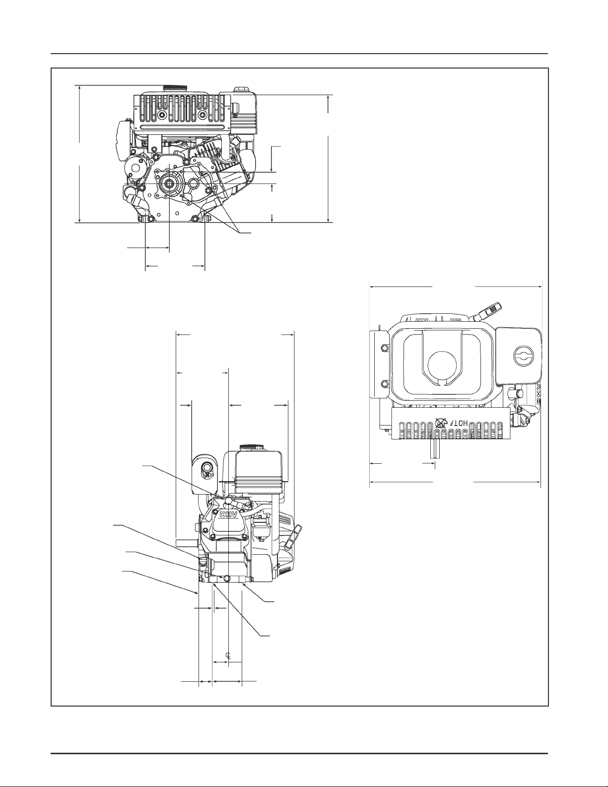
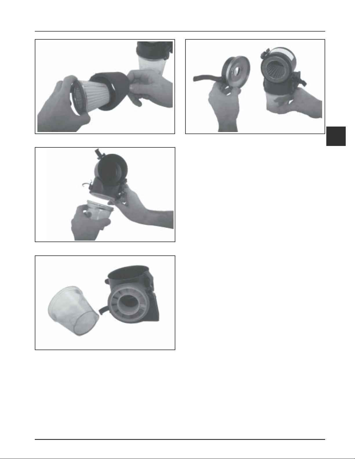
Figure 4-8. Removing Heavy-Duty Precleaner.
Figure 4-9. Removing Heavy-Duty Lower Chamber.
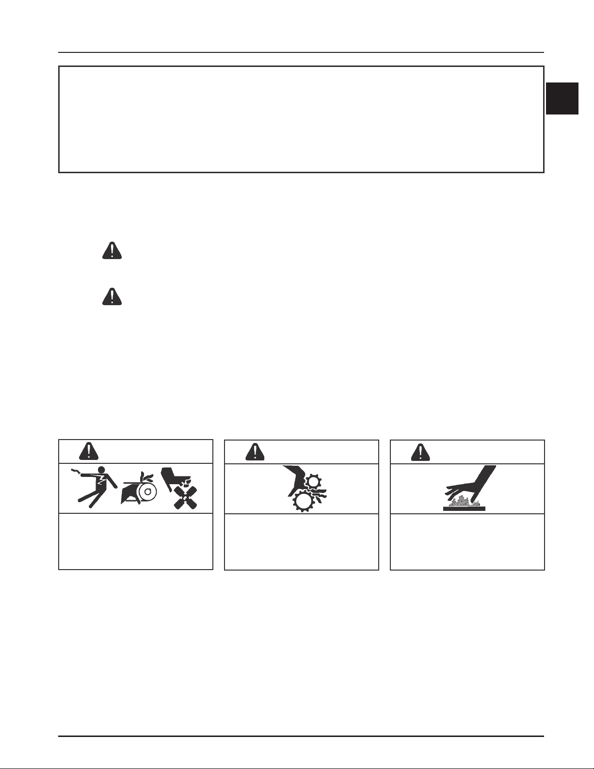
Figure 4-11. Inst alling Heavy-Duty Cover/Housing.
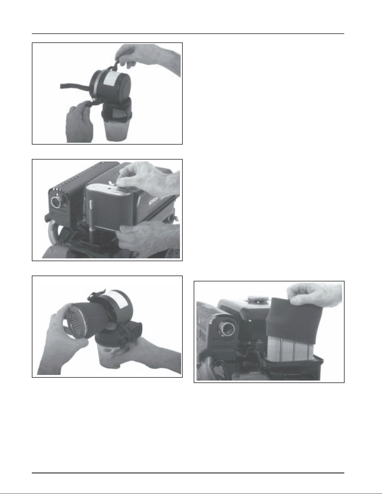
Paper Element Service
Every 100 hours of operation (more often under
extremely dusty or dirty conditions), check the paper
element. Replace the element as necessary. Follow
these steps:
1. Standard Air Cleaner:
Loosen the air cleaner cover knob and remove the
cover. Remove the wing nut and lift off the air
cleaner element with precleaner. Remove the
precleaner from the paper element. Service the
precleaner.
Heavy-Duty, Cyclonic Air Cleaner:
Unhook the latches and remove the housing
assembly from the mounting base. Remove the
wing nut (some models) securing air cleaner/
precleaner assembly, or pull the complete filter
assembly out of the housing. Remove the
precleaner from the paper element. Service the
precleaner.
2. Do not wash the paper element or use
pressurized air, as this will damage the element.
Replace a dirty, bent, or damaged element with a
genuine Kohler element. Handle new elements
carefully; do not use if the sealing surfaces are
bent or damaged.
4
Figure 4-10.
4.3
Page 30

Section 4
Air Cleaner and Air Intake System
3. When servicing the air cleaner, check the air
cleaner base, and cover/housing assembly. Make
sure it is secure and not bent or damaged. On a
heavy-duty air cleaner, unsnap the latches and
clean out the lower swirl/dirt chamber. See Figure
4-9. Make sure the air slots in the upper section of
the housing and in the lower chamber are open.
See Figure 4-10. Clean and inspect all
components for damage or improper fit. Replace
any components which are bent or damaged.
Reassemble the lower chamber (heavy duty air
cleaners).
NOTE: Before the air cleaner is reassembled make
sure the rubber seal is in position on the stud
(standard only). Also inspect the foam seal on
the base of the filter element, do not use if the
condition of either is questionable in any way.
Replace it with a new part before
reassembling.
4. Standard Air Cleaner:
Install the serviced precleaner over the element.
Position the element/precleaner assembly on the
base and secure with the wing nut. Reinstall the air
cleaner cover and tighten securely. See Figure 4-5.
Heavy-Duty Cyclonic Air Cleaner
Make sure the main housing, lower swirl/dirt
chamber, mounting hardware and latches are not
damaged, bent or broken; affecting the sealing ability
and operation of air cleaner housing. Clean and check
all components as well as the airflow passages.
Air Cleaner Base
Make sure the air cleaner base is secured tightly to
carburetor and not cracked, bent or damaged,
preventing a proper seal.
Breather T ube
Make sure the breather tube is in good condition and
connected to the air cleaner base or adapter and the
breather cover. Replace the tube if it is cracked or
damaged.
Heavy-Duty Cyclonic Cleaner:
Place the precleaner over the element and install
it as an assembly into the cover/housing. Insert
the small end first, into the housing, so the larger
end with the foam seal is out (visible). Secure
with the wing nut (if used). Secure the cover/
housing with the latches. See Figure 4-11.
Air Cleaner Components
Whenever the air cleaner cover is removed, or the
paper element or precleaner is serviced, check the
following:
Standard Air Cleaner
Make sure the element cover is not bent, distorted or
damaged. Make sure the wing nut and rubber sleeve
seal on the base stud are in place and in good
condition, ensuring the element is sealed against
leakage. (Some models the seal is fixed).
If the air cleaner element has a foam seal on the
bottom, make sure it is in good condition and not
damaged. See Figure 4-12.
Figure 4-12. Foam Seal.
Figure 4-13. Cutaway View .
4.4
Page 31

Section 4
Air Intake and Air Cleaner System
CS8.5 (spec. 95xxxx) engines use an air cleaner base
with a serviceable rubber base pad to seal the air filter
element on the bottom. See Figure 4-14. Make sure the
pad is installed, clean, and in good condition.
Figure 4-14. Serviceable Rubber Base Pad.
Foam Air Cleaner Element
To service the foam element perform the following
steps:
1. Remove the two screws and the outer air cleaner
cover/housing. See Figure 4-16.
Mounting Screw
4
Mounting Screw
Figure 4-16. Mounting Details.
2. Remove the foam element from the air cleaner
housing. See Figure 4-17.
Figure 4-15. Foam Air Cleaner Configuration.
Check the air cleaner daily or before starting the
engine. Check for buildup of dirt and debris, along
with loose or damaged components.
NOTE: Operating the engine with loose or damaged
air cleaner components could allow
unfiltered air into the engine causing
premature wear and failure.
Every 50 hours of operation, wash and reoil the foam
air cleaner element (more often under extremely
dusty, or dirty conditions). Replace the foam element
with a new genuine Kohler element if deteriorated or
damaged in any way.
Foam Air
Cleaner Element
Figure 4-17. Foam Air Cleaner Element Det ails.
3. Wash the foam element in warm water with
detergent. Rinse the element thoroughly until all
traces of detergent are eliminated. Squeeze out all
excess water (do not wring). Allow the element to
air dry.
4. Lightly oil the element with new engine oil.
Squeeze element to evenly distribute the oil and
remove any excess.
4.5
Page 32

Section 4
Air Cleaner and Air Intake System
5. When servicing the foam air cleaner element,
clean and check the air cleaner case and outer
cover for damage, distortion, or an improper seal.
Replace any components which are bent or
damaged.
6. Make sure the square metal fitting plate is
properly positioned within the case. See Figure
4-17.
7. Reinstall the outer cover and secure with the two
screws. See Figure 4-16.
NOTE: Do not operate engine without the air cleaner
element; excessive piston and/or cylinder
wear may result.
Air Intake/Cooling System
To ensure proper cooling, make sure the grass screen,
cooling fins and other external surfaces of the engine
are kept clean at all times.
Every 100 hours of operation (more often under
extremely dusty or dirty conditions), remove the
blower housing and other cooling shrouds. Clean the
cooling fins and external surfaces as necessary. Make
sure the cooling shrouds are reinstalled.
NOTE: Operating the engine with a blocked grass
screen, dirty or plugged cooling fins, and/or
cooling shrouds removed, will cause engine
damage due to overheating.
4.6
Page 33

Fuel System and Governor
Section 5
Fuel System and Governor
Section 5
Description
WARNING: Explosive Fuel!
Gasoline is extremely flammable and its vapors can explode
if ignited. Store gasoline only in approved containers, in
well ventilated, unoccupied buildings, away from sparks or
flames. Do not fill the fuel tank while the engine is hot or
running, since spilled fuel could ignite if it comes in contact
with hot parts or sparks from ignition. Do not start the
engine near spilled fuel. Never use gasoline as a cleaning
agent.
Fuel System Components
The typical fuel system includes the following
components:
• Fuel Tank
• Shut-off Valve with Screen Filter
• Fuel Tank Inlet Filter
• Carburetor
• Fuel Line
Operation
The fuel from the tank is moved through the shut-off
valve/screen filter and fuel lines by gravity.
• Do not use gasoline left over from the previous
season, to minimize gum deposits in your fuel
system and to insure easy starting.
• Do not add oil to the gasoline.
• Do not overfill the fuel tank. Leave room for the
fuel to expand.
Fuel T yp e
For best results, use only clean, fresh, unleaded
gasoline with a pump sticker octane rating of 87 or
higher. In countries using the Research fuel rating
method, it should be 90 octane minimum.
Unleaded gasoline is recommended, as it leaves less
combustion chamber deposits. Leaded gasoline may
be used in areas where unleaded is not available and
exhaust emissions are not regulated.
Gasoline/Alcohol blends
Gasohol (up to 10% ethyl alcohol, 90% unleaded
gasoline by volume) is approved as a fuel for Kohler
engines. Other gasoline/alcohol blends are not
approved.
5
Fuel then enters the carburetor float bowl and is
drawn into the carburetor throat. There, the fuel is
mixed with air. This fuel-air mixture is then burned in
the engine combustion chamber.
Fuel Recommendations
General Recommendations
Purchase gasoline in small quantities and store in
clean, approved containers. A container with a
capacity of 2 gallons or less with a pouring spout is
recommended. Such a container is easier to handle
and helps eliminate spillage during refueling.
Gasoline/Ether blends
Methyl Tertiary Butyl Ether (MTBE) and unleaded
gasoline blends (up to a maximum of 15% MTBE by
volume) are approved as a fuel for Kohler engines.
Other gasoline/ether blends are not approved.
Fuel Filters
Serviceable screen filters are located within the inlet of
the fuel tank and the shut-off valve. Periodically
inspect and clean or replace as required.
5.1
Page 34

Section 5
Fuel System and Governor
Fuel Line
In compliance with CARB Tier III Emission
Regulations, engines with a “Family” identification
number beginning with “6” or greater (see Figure
5-1), must use Low Permeation SAE 30 R7 rated fuel
line; certified to meet CARB requirements. Standard
fuel line may not be used. Order replacement hose by
part number through a Kohler Engine Service Dealer.
Fuel System Tests
When the engine starts hard, or turns over but will
not start, it is possible that the problem is in the fuel
system. To find out if the fuel system is causing the
problem, perform the following tests.
IMPORTA NT ENGINE INFORMATION
THIS ENGINE MEETS U.S. EPA PHASE II, 2002-
2005 CALIFORNIA AND EC STAGE II (SN:4)
EMISSION CONTROL REGS FOR SI SMALL OFF–
ROAD ENGINES
F AMILY 6 YYMXS.1171 EA
TYPE APP
MODEL NO.
SPEC. NO.
DISPL. (CC)
SERIAL NO.
OEM PROD. NO.
EMISSION COMPLIANCE PERIOD:
EPA: CATEGORY A
CERTIFIED ON: UNLEADED GASOLINE
REFER TO OWNER'S MANUAL FOR SAFETY,
MAINTENANCE SPECS, AND ADJUSTMENTS
1-800-544-2444 www.kohlerengines.com
KOHLER CO. KOHLER, WISCONSIN USA
(REF:_______________ )
Troubleshooting – Fuel System Related Causes
1. Check the following:
a. Make sure the fuel tank contains clean, fresh,
proper fuel.
b. Make sure the vent in the fuel cap is open.
c. Make sure the fuel valve is open.
2. Check for fuel in the combustion chamber.
a. Disconnect and ground the spark plug lead.
b. Close the choke on the carburetor.
c. Crank the engine several times.
d. Remove the spark plug and check for fuel at
the tip.
3. Check for fuel flow from the tank to the
carburetor.
a. Remove the fuel line from the inlet fitting of
the carburetor.
b. Hold the line below the bottom of the tank.
Open the shut-off valve and observe flow.
N432
Figure 5-1. “Family” Number Location.
ConclusionTest
2. If there is fuel at the tip of the spark plug, fuel is
reaching the combustion chamber.
If there is no fuel at the tip of the spark plug,
check for fuel flow from the fuel tank. (Test 3)
3. If fuel does flow from the line, check for a
problem in the carburetor (dirt, gum, varnish,
etc.).
If fuel does not flow from the line, check for a
clogged fuel cap vent, inlet filter, shut-off valve
screen filter, and/or fuel line(s).
Carburetor
General
The CS engines use fixed jet MIKUNI carburetors. The
fixed main jet carburetor is designed to deliver the
correct fuel-to-air mixture to the engine under all
5.2
operating conditions. The high idle mixture is set at
the factory and cannot be adjusted. The low fuel
adjusting needle is also set at the factory and normally
does not need adjustment.
NOTE: Carburetor adjustments should be made only
after the engine has warmed up.
Page 35

Condition
1. Engine starts hard, runs
roughly or stalls at idle
speed.
Section 5
Fuel System and Governor
Troubleshooting – Carburetor Related Causes
Possible Cause/Probable Remedy
1. Low idle fuel mixture/speed improperly adjusted. Adjust the low idle
speed RPM, then adjust the low idle fuel needle.
2. Engine runs rich.
(Indicated by black, sooty
exhaust smoke, misfiring,
loss of speed and power,
governor hunting, or
excessive throttle
opening.)
3. Engine runs lean.
(Indicated by misfiring,
loss of speed and power,
governor hunting, or
excessive throttle
opening.)
4. Fuel leaks from carburetor.
2a. Clogged air cleaner. Clean or replace.
b. Choke partially closed during operation. Check the choke lever/linkage
to ensure choke is operating properly.
c. Low idle fuel mixture is improperly adjusted. Adjust low idle fuel
needle.
d. Float level is too high. Separate carburetor bowl from carburetor body,
check float setting against specification. Replace float if required.
e. Dirt under the fuel inlet needle. Remove needle; clean needle and seat
and blow out with compressed air.
f. Bowl vent pilot jet or air bleeds plugged. Remove low idle fuel adjusting
needle. Clean vent, ports, and air bleeds. Blow out all passages with
compressed air.
g. Leaky, cracked, or damaged float. Submerge float to check for leaks.
3a. Low idle fuel mixture is improperly adjusted. Adjust low idle fuel
needle.
b. Float level is too low. Separate carburetor bowl from carburetor body,
check float setting against specification. Replace float if required.
c. Idle holes plugged; dirt in fuel delivery channels. Remove low idle fuel
adjusting needle. Clean main fuel jet and all passages; blow out with
compressed air.
4a. Float level too high. See Remedy 2d.
b. Dirt under fuel inlet needle. See Remedy 2e.
c. Bowl vent plugged. Blow out with compressed air.
d. Carburetor bowl gasket leaks. Replace gasket.
5
Troubleshooting Checklist
If engine troubles are experienced that appear to be
fuel system related, check the following areas before
adjusting or disassembling the carburetor.
• Make sure the fuel tank is filled with clean, fresh
gasoline.
• Make sure the fuel cap vent and inlet filter are not
blocked and operating properly.
• Make sure fuel is reaching the carburetor. This
includes checking the fuel shut-off valve, screen
filters, and fuel lines for restrictions.
• Make sure the air cleaner base and carburetor are
securely fastened to the engine using gaskets in
good condition.
• Make sure the air cleaner element is clean and all
air cleaner components are fastened securely.
• Make sure the ignition system, governor system,
exhaust system, and throttle and choke controls
are operating properly.
If, after checking all items listed above, the engine is
hard to start, runs roughly, or stalls at low idle speed,
it may be necessary to adjust or service the carburetor.
5.3
Page 36

Section 5
Fuel System and Governor
Adjustments
General
NOTE: Carburetor adjustments should be made only
after the engine has warmed up.
The carburetor is designed to deliver the correct fuelto-air mixture to the engine under all operating
conditions. The high idle mixture is set at the factory
and cannot be adjusted. The low idle fuel adjusting
needle is also set at the factory and has a limiting cap.
It normally does not need adjustment.
Adjusting Low Idle Fuel and Speed
NOTE: Certified engines have a limiter cap on the
idle fuel adjusting needle. Adjustment can
only be performed within the limits allowed
by the cap.
1. Start engine and run at half throttle for 5 to 10
minutes to warm up. The engine must be warm
before making final settings.
2. Low Idle Fuel Needle Setting: Place the throttle
into the ‘‘idle’’ or ‘‘slow’’ position. Turn the low
idle fuel adjusting needle in or out within the
adjustment range, to obtain the best low speed
performance.
3. Low Idle Speed Setting: Place the throttle control
into the ‘‘idle’’ or ‘‘slow’’ position. Set the low
idle speed to 2000 RPM* (± 150 RPM) by turning
the low idle speed adjusting screw in or out.
Check the speed using a tachometer.
*NOTE: The actual low idle speed depends on
the application – refer to equipment
manufacturer's recommendations. The
recommended low idle speed for basic
engines is 2000 RPM. To ensure best
results when setting the low idle fuel
needle, the low idle speed must not
exceed 2000 RPM (± 150 RPM).
Idle Speed
Screw
Idle Fuel
Needle with
Limiter Cap
Figure 5-2. Carburetor Adjustment s.
5.4
Page 37

18
Section 5
Fuel System and Governor
1
17
16
15
13
14
22
21
2
20
3
17
4
5
6
7
19
18
16
15
14
13
1
2
3
4
5
6
5
7
8
9
12
9
10
11
1. Pilot Jet
2. Screw
3. Main Jet
4. Main Nozzle
5. Float
6. Float Pin
7. Float Gasket
8. Drain Plug
9. Spring
10. Washer
Figure 5-3. CS4 and CS6 Carburetor - Exploded
View.
11. Bowl Retaining
Screw
12. Float Bowl
13. Clip
14. Needle Assembly
15. Spring
16. Idle Fuel Adjusting
Screw
17. Limiter Cap
18. Screw
8
11
12
1. Pilot Jet
2. Plug Screw Washer
3. Seal
4. Main Jet
5. Screw
6. Main Nozzle
7. Main Pipe
8. Float
9. Float Gasket
10. Drain Plug
11. Gasket
12. Bowl Retaining
Screw
Figure 5-4. CS8.5-12 Carburetor - Exploded View.
13. Float Pin
14. Clip
15. Needle Assembly
16. Spring
17. Throttle Adjusting
Screw
18. Spring
19. Idle Fuel Adjusting
Screw
20. Limiter Cap
21. Screw
22. Ball
10
5.5
Page 38

Section 5
Fuel System and Governor
Carburetor Service
If symptoms described in the carburetor
troubleshooting guide indicate a problem within the
carburetor, the following steps can be used to remove
the carburetor from the engine and provide the
necessary service.
1. Remove the air cleaner cover, wing nut, filter
element with precleaner, the air cleaner base
mounting screws and hex flange nuts from the
mounting bracket(s) and main mounting studs.
2. Disconnect the breather hose from the valve cover
or air cleaner base, and remove the base from the
engine.
3. Disconnect the fuel line from the carburetor inlet.
4. Disconnect the choke link and spring at the
carburetor end (CS8.5-12 only).
Figure 5-5. Float Height Position.
5. Slide the carburetor off of the mounting studs
while disconnecting the throttle link and
dampening spring.
6. Clean all dirt and debris from exterior of
carburetor.
7. Remove the screw from the bottom center of
carburetor bowl. Carefully separate the bowl
from the main body and remove the bowl gasket
from the body.
8. Place the carburetor in an inverted position. Lift
up the float so that the tip of the float valve
lightly contacts the float arm. See Figure 5-5.
Measure the float height from the casting surface
as illustrated in Figure 5-6. Float height for the
CS4 and CS6 is 16 mm (0.63 in.). Float height for
the CS8.5, CS10, and CS12 is 14.9 mm (0.59 in.).
Install a float kit if the float height is incorrect.
Float Kit Contains:
Qty
1
1
1
1
2
1
Description
Float
Gasket, bowl
Gasket, bowl screw
Pin, float
Gasket, intake
Gasket, air cleaner base
Figure 5-6. Measuring Float Height.
CAUTION
Do not bend the float in an attempt to reset the height. The
correct float height is determined by the design of the inlet
needle and float. There is no provision for physical
adjustment.
9. Check to see if the fuel inlet needle or seat is
dirty, obstructed or worn.
a. Remove the main jet from the side of the
tower.
b. Grab the exposed end of the float pin with a
needle nose pliers and pull it out.
c. Lift out the float and inlet needle. Slide the
inlet needle and clip off of the float tab.
d. Check components for contamination, wear,
or damage. See Figure 5-7. Use carburetor
cleaner to clean out any dirt or
contamination. Use a float kit if the inlet
needle or float is damaged or worn. If the inlet
seat is damaged or worn, the carburetor must
be replaced.
5.6
Page 39

Section 5
Fuel System and Governor
Grooved Wear
Dust
Figure 5-7. Inlet Needle and Seat Wear/Damage
Details.
10. After the parts have been cleaned or exchanged,
slide the inlet needle onto the float tab, reinstall
the float assembly into the carburetor, and verify
that the correct float height has been restored.
11. If there were gum or varnish deposits in the area
of the inlet needle and seat, there is a good
possibility that the main nozzle may also need
cleaning before the bowl is reinstalled. The main
nozzle is threaded into the tower and can be
removed for cleaning, but be careful not to
damage it, as it is not available as a service part.
Governor
These engines are equipped with a centrifugal
flyweight mechanical governor. The governor is
designed to hold the engine speed constant under
changing load conditions. The governor gear/
flyweight mechanism is mounted inside the crankcase
and driven off the gear on the crankshaft.
Operation
Centrifugal force acting on the rotating governor gear
assembly causes the flyweights to move outward as
speed increases. See Figure 5-8. As the flyweights
move outward, they cause the regulating pin to extend
from the governor gear assembly.
Speed Increasing
Speed Decreasing
5
a. Use a thin, flat blade screwdriver to remove
the nozzle from the tower. If it does not turn
easily, use some carburetor cleaner to clean
the exposed threads in the tower.
b. Soak the nozzle in carburetor cleaner to
remove any deposits and blow it dry with
compressed air.
c. Reinstall it in the tower and thread it in until
it bottoms.
12. Reinstall the main jet and install the bowl gasket
in the groove. Reassemble the bowl to the
carburetor with the screw removed in step 7.
Position the bowl so the drain screw will be
accessible after the carburetor is mounted to the
engine.
13. Use the reverse of steps 1-5 to reinstall the
carburetor on the engine.
Figure 5-8. Action of Governor Gear.
The regulating pin contacts the tab on the cross shaft,
causing the shaft to rotate when the engine speed
changes. See Figure 5-9. One end of the cross shaft
protrudes through the side of the closure plate.
Through external linkage attached to the cross shaft,
the rotating action is transmitted to the throttle lever
of the carburetor.
When the engine is at rest, and the throttle control is
in the ‘‘fast’’ position, the tension of the governor
spring holds the throttle plate open. When the engine
is operating (the governor gear assembly is rotating),
the force applied by the regulating pin against the
cross shaft tends to close the throttle plate. The
governor spring tension and the force applied by the
regulating pin are in ‘‘equilibrium’’ during operation,
holding the engine speed constant.
5.7
Page 40

Section 5
Fuel System and Governor
When a load is applied and the engine speed (and
governor gear speed) decreases, the governor spring
tension moves the governor lever to open the throttle
plate wider. This allows more fuel into the engine,
increasing engine speed. (This action occurs very
rapidly, so a reduction in speed is hardly noticed.) As
the speed reaches the governed setting, the governor
spring tension and the force applied by the regulating
pin will again be in equilibrium. This maintains the
engine speed at a relatively constant level.
The governed speed setting is determined by the
position of the throttle control. It can be variable or
constant, depending on the application.
6. Hold both in this position and tighten the
governor lever bolt.
Torque the bolt to:
8 N·m (70.8 in. lb.) on CS4, CS6
10 N·m (88.5 in. lb.) on CS8.5, CS10, CS12
Governor
Shaft
Governor
Lever
Mounting
Bolt
Figure 5-10. CS4, CS6 Governor Adjustment.
Governor Shaft
Figure 5-9. Governor System.
Initial Adjustment
Make this initial adjustment whenever the governor
lever is loosened or removed from the cross shaft. To
ensure proper setting, make sure the throttle linkage is
connected to the governor lever and to the carburetor
throttle lever (certain engine components removed for
clarity of illustration).
Governor Adjustment
1. Close the fuel shut-off valve.
2. Remove the air cleaner outer cover. Then either
reposition the fuel tank to access governor shaft
and lever joint, or disconnect the fuel line and
remove the tank from the engine.
NOTE: Make sure the carburetor is mounted
and secured in place when adjustment is
being made/checked.
3. Loosen the governor lever mounting bolt.
4. Move the governor lever clockwise until it stops.
5. Rotate the governor shaft clockwise until it stops.
Mounting
Bolt
Figure 5-11. CS8.5 (spec. 92xxxx), CS10, and CS12
Governor Adjustment.
Figure 5-12. CS8.5 (spec. 95xxxx) Governor
Adjustment.
Governor Lever
5.8
Page 41

High Idle Speed Adjustment
The recommended maximum no-load high idle speed
for the CS engines is 3750 RPM (± 100 RPM) for
tapered shaft models, and 3800 RPM (± 100 RPM) for
all others. The actual high idle speed depends on the
application. Refer to the equipment manufacturer's
instructions for specific information.
The high idle speed is set by turning the throttle stop
screw on the throttle lever bracket assembly in or out.
See Figures 5-13 to 5-15 and follow the procedures
below.
Section 5
Fuel System and Governor
1. Start the engine and allow it to warm up. Place
the throttle control lever into the ‘‘fast’’ or high
idle position.
2. Check the engine speed with a tachometer.
3. To increase the high idle speed–turn the high
idle speed adjusting screw out
(counterclockwise), while applying light pressure
to the throttle control lever in the
counterclockwise direction (away from the
carburetor).
To decrease the high idle speed–turn the high
idle speed adjusting screw in (clockwise), until
the desired engine speed is attained.
Throttle Stop Screw Throttle Lever
Figure 5-14. CS8.5 (spec. 92xxxx), CS10, and CS12
Throttle Lever/Throttle Stop Screw Details.
5
Throttle Stop
Screw
Throttle Lever
Figure 5-15. CS8.5 (spec. 95xxxx) Throttle Lever/
Throttle Stop Screw Details.
Throttle Stop
Screw
Figure 5-13. CS4, CS6 Throttle Lever/Throttle Stop
Screw Details.
Throttle Lever
5.9
Page 42

Section 5
Fuel System and Governor
Low Idle Speed Adjustment
The recommended low idle speed is 2000 RPM
(± 100 RPM). The low idle speed is set by turning the
low idle speed screw in or out, see Figures 5-16 and
5-17.
1. With the engine warm, move the throttle lever
clockwise until it stops.
2. Check the idle speed with a tachometer.
3. Turn the adjustment screw in (clockwise) to
increase the idle speed, or out (counterclockwise)
to decrease the idle speed, until the correct speed
is attained.
Adjusting Screw
Figure 5-17. CS8.5-12 Low Idle Speed Adjusting
Screw.
Adjusting Screw
Figure 5-16. CS4, CS6 Low Idle Speed Adjusting
Screw.
5.10
Page 43

Section 6
Lubrication System
General
These engine use a splash lubrication system,
supplying necessary lubrication to the crankshaft,
camshaft, connecting rod and valve train components.
Oil Recommendations
Using the proper type and weight of oil in the
crankcase is extremely important. So is checking oil
daily and changing oil regularly. Failure to use the
correct oil or using dirty oil can cause premature
engine wear and failure.
Oil T ype
Use high quality detergent oil of API (American
Petroleum Institute) service class SG, SH, SJ or
higher. Select the viscosity based on the air
temperature at the time of operation as shown in the
following table.
Section 6
Lubrication System
Figure 6-1. Oil Container Logo.
6
Check Oil Level
The importance of checking and maintaining the
proper oil level in the crankcase cannot be
overemphasized. Check oil BEFORE EACH USE as
follows:
Synthetic oils should not be used.
NOTE: Using other than service class SG, SH, SJ or
higher oil or extending oil change intervals
longer than recommended can cause engine
damage.
A logo or symbol on oil containers identifies the API
service class and SAE viscosity grade. See Figure 6-1.
1. Make sure the engine is stopped, level, and is
cool so the oil has had time to drain into the
sump.
2. Clean the area around the oil fill cap to keep dirt,
debris, etc., out of the engine.
3. Unthread and remove the oil fill cap.
4. The oil level should be at the point of
overflowing out of the filler neck. See Figure 6-2.
6.1
Page 44

Section 6
Lubrication System
Bring Level Up To
Point of Overflow
Proper
Oil Level
Low Oil
Level
NOTE: If the engine stalls or does not start, turn the
engine switch to the ‘‘on’’ position and
attempt to start the engine. If the oil warning
light flickers for a few seconds, the engine oil
is insufficient. Add oil and restart.
NOTE: Make sure the oil level is checked BEFORE
EACH USE and is maintained up to the point
of overflowing the filter neck.
Figure 6-2. Cutaway Showing Proper Oil Level.
5. If the level is low add oil of the proper type to
bring the level up to the point of overflowing.
NOTE: To prevent extensive engine wear or damage,
always maintain the proper oil level in the
crankcase. Never operate the engine with the
oil below the low oil level.
NOTE: Just because you can see oil in the crankcase
doesn't mean the level is in the safe range.
Bring the level up to the point of overflowing
the filler neck.
Oil Sentry™
Some engines are equipped with an Oil Sentry™ oil
monitor. When the oil level falls below the safe level,
the engine stops automatically. Unless you refill with
oil, the engine will not start again. See Figure 6-3.
Change Oil
For a new engine, change oil after the first 20 hours of
operation. Thereafter, change oil after every 100 hours
of operation.
For an overhauled engine, use 10W-30 weight service
class SG, SH, SJ or higher oil for the first 5 hours of
operation. Change the oil after this initial
run-in period. Refill with service class SG, SH, SJ or
higher oil as specified in the “Viscosity Grades” table
on page 6.1.
Change the oil while the engine is still warm. The oil
will flow more freely and carry away more impurities.
Make sure the engine is level when filling, checking,
and changing the oil.
Change the oil as follows:
1. To keep dirt and debris out of the engine, clean
the area around the oil fill/check plug before
removing it.
2. Remove the oil drain plug and oil fill/check plug.
Be sure to allow ample time for complete
drainage.
Figure 6-3. Oil Sentry™ Operation.
6.2
3. Reinstall the drain plug. Make sure it is tightened
to 17.6 N·m (13 ft. lb.) torque.
4. Fill the crankcase, with new oil of the proper
type, up to the point of overflowing the filler
neck. Refer to ‘‘Oil Type’’ on page 6.1. Always
check the level before adding more oil.
5. Reinstall the oil fill/check plug and tighten
securely.
Page 45

NOTE: To prevent extensive engine wear or damage,
always maintain the proper oil level in the
crankcase. Never operate the engine with the
oil level below the low oil level.
Figure 6-4. CS4, CS6 Right Oil Fill/Level Plug
Location.
Section 6
Lubrication System
Figure 6-6. CS8.5-12 Right Oil Fill/Level Plug
Location.
Figure 6-5. CS4, CS6 Left Oil Fill/Level Plug
Location.
6
Figure 6-7. CS8.5-12 Left Oil Fill/Level Plug
Location.
6.3
Page 46

Section 7
Retractable Starter
Section 7
Retractable Starter
WARNING: S pring Under Tension!
Retractable starters contain a powerful, recoil spring that is under tension. Always wear safety goggles when servicing
retractable starters and carefully follow instructions in this section for relieving spring tension.
Pawl Repair
Starter
Handle
Starter
Rope
Kit
Drive Cup
Center Screw
Drive Plate
Friction Spring
Drive Pawl
Spring
7
Starter
Housing
Figure 7-1. Retractable St arter - Exploded V iew.
To Remove Starter
1. Remove the hex flange screws (three on CS4 and
CS6, four on CS8.5-12) securing the starter
assembly to the blower housing.
2. Remove the starter assembly.
To Install Starter
1. Align the retractable starter with the mounting
locations on the blower housing, and install the
hex flange screws. Leave the screws slightly
loose.
Pulley
Recoil
Spring
Figure 7-2. Installing Retractable St arter.
7.1
Page 47

Section 7
Retractable Starter
2. Pull the starter handle out until the pawls engage
the drive cup. Hold the handle in this position
and torque the screws to 5.5 N·m (48 in. lb.). See
Figure 7-3.
Figure 7-3. Engage Pawls and Tighten Mounting
Screws.
Rope Replacement
The rope can be replaced without complete starter
disassembly.
5. When all spring tension on the starter pulley is
released, remove the rope from the pulley.
6. Tie a single knot in one end of the new rope.
7. Rotate the pulley counterclockwise to pre-tension
the spring (approximately 4 full turns of pulley
on CS4 and CS6; approximately 5 full turns of
pulley on CS8.5-12).
8. Rotate the pulley until the rope hole in pulley is
aligned with the rope guide bushing of the starter
housing.
NOTE: Do not allow the pulley/spring to
unwind. Enlist the aid of a helper if
necessary.
9. Feed the unknotted end of the rope through the
rope hole in the starter pulley and rope guide
bushing of the housing. See Figure 7-5.
1. Remove the starter from the engine blower
housing.
2. Pull the rope out approximately 12" and tie a
temporary (slip) knot in it to keep it from
retracting into the starter. See Figure 7-4.
Figure 7-4. Removing Starter Handle.
3. Pull the knot end out of the handle, untie the
knot, and slide the handle off.
Figure 7-5. Installing Rope.
10. Tie a slip knot approximately 12" from the free
end of rope. Hold the pulley firmly and allow it
to rotate slowly until the slip knot reaches the
guide bushing of the housing.
11. Slip the handle onto the rope. Tie a single knot at
the end of the rope.
12. Untie the slip knot and pull on the handle until
the rope is fully extended. Slowly retract the rope
into the starter. If the spring is properly
tensioned, the rope will retract fully and the
handle will stop against the starter housing.
4. Hold the pulley firmly and untie the slip knot.
Allow the pulley to rotate slowly as the spring
tension is released.
7.2
Page 48

Section 7
Retractable Starter
Pawl (Dogs) Replacement
Only partial disassembly of the starter is necessary to
replace the pawls. Pawl repair kits are available which
include the following components:
CS4 and CS6 Pawl Repair Kit Contains
Qty
1
1
1
2
CS8.5-12 Pawl Repair Kit Contains
Qty
1
1
2
1
2
Description
Drive Plate
Center Screw
Clip
Starter Pawl (Dog)
Description
Drive Plate
Center Screw
Pawl (Dog) Spring
Clip
Starter Pawl (Dog)
Disassembly
WARNING: S pring Under Tension!
Do not remove the center screw from starter until the
spring tension is released. Removing the center screw before
releasing spring tension, or improper starter disassembly,
can cause the sudden and potentially dangerous release of
the spring. Follow these instructions carefully to ensure
personal safety and proper starter disassembly. Make sure
adequate face protection is worn by all persons in the area.
1. Release recoil spring tension by:
CS4, CS6: Loosen the center screw approximately
1 turn. Rotate the pulley against spring tension
until the pulley rope hole with knot is adjacent to
outlet in housing. Lift up the slack in rope
between pulley and housing, slowly allow the
pulley to unwind, releasing the spring tension.
Count the number of rotations for reassembly
later.
2. Unscrew the center screw and lift off the drive
plate. The center screw will be captured by the
clip around the shoulder on backside of plate.
3. Note the positions of the pawls and pawl springs
(CS8.5-12 only) before removing. Remove parts
from pulley.
4. Carefully inspect the components for wear,
cracks, and/or damage. Replace all worn or
damaged components. Use only genuine Kohler
replacement parts as specified in the parts
manuals. All components shown in Figure 7-1 are
available as service parts. Do not use nonstandard
parts.
5. Install pawl springs (CS8.5-12 only) and pawls
onto pawl studs of pulley. All parts must be dry.
Pawl
7
Pawl Spring
Figure 7-6.
6. Position the drive plate over the pawls, aligning
the actuating slots in the plate with the raised
sections on each drive pawl. Torque the center
screw to 5-6 N·m (44-53 in. lb.). Rotate the pulley
by hand and check operation. See Figure 7-7.
CS8.5-12: Rotate the pulley against spring
tension, until the cutout in pulley is adjacent to
outlet in housing. Lift up the slack in rope
through the cutout and slowly allow pulley to
unwind, releasing spring tension. Count the
number of rotations for reassembly later.
7.3
Page 49

Section 7
Retractable Starter
Clip
Drive Plate
Figure 7-7. Drive Plate and Pawl Details.
7. Rehook the slack in rope into notch of pulley and
rotate the pulley counterclockwise (viewed from
pawl side) to re-tension the spring
(approximately 4 full turns on CS4 and CS6;
approximately 5 full turns on CS8.5-12).
Recoil Spring, Pulley, and/or Housing
Replacement
Disassembly
1. Release spring tension and remove the handle
and starter rope. (Refer to ‘‘Rope Replacement’’.)
2. Unscrew the center screw and lift off the drive
plate. The screw will be captured within plate by
the clip on backside.
3. Carefully note the positions of the pawls and
pawl springs (CS8.5-12 only) before removing
them. Remove the parts from the starter pulley.
4. Rotate the pulley clockwise (1/2 to 1 full turn) this
will ensure the spring is disengaged from the
starter housing.
5. Carefully lift the pulley out of the recoil housing,
while reaching through the spokes of the pulley
to keep the spring from coming out of the pulley.
6. Wearing adequate eye/face protection, carefully
remove the spring from the pulley cavity.
7. Clean all parts including the starter spring cavity
in pulley and recoil housing of all old grease and
dirt. Inspect all parts for wear or damage and
replace as required.
Figure 7-8. Retractable St arter Pawl Assembly
Details.
WARNING: S pring Under Tension!
Do not remove the center screw from starter until the
spring tension is released. Removing the center screw before
releasing spring tension, or improper starter disassembly,
can cause the sudden and potentially dangerous release of
the spring. Follow these instructions carefully to ensure
personal safety and proper starter disassembly. Make sure
adequate face protection is worn by all persons in the area.
7.4
Figure 7-9. Disassembled Retractable St arter .
Reassembly
1. Generously lubricate the recoil spring with a
commercially available bearing grease.
2. Engage the outer spring hook into the pulley
‘‘slit’’ opening, then carefully wind the spring
counterclockwise into the drum of the pulley
from larger to smaller diameter.
Page 50

3. Carefully install pulley into recoil housing,
engaging the spring hook with starter housing
tab. See Figure 7-10.
NOTE: Rotating pulley counterclockwise
slightly will assist engagement.
4. Install the pawl springs (CS8.5-12 only) and
pawls onto pawl studs of pulley.
Section 7
Retractable Starter
Figure 7-11. Torque Center Mounting Screw.
6. Tension the spring and install the rope and
handle as outlined in Steps 6 through 12 under
‘‘Rope Replacement.’’
7. Install the recoil starter to engine blower housing
but do not fully tighten the mounting screws.
Figure 7-10. Assembling St arter Pulley to Housing.
5. Mount drive plate over pawls onto pulley,
aligning the actuating slots in plate with the
raised sections on each drive pawl. Torque the
screw to 5-6 N·m (44-53 in. lb.). Rotate the pulley
by hand and check operation. See Figure 7-11.
8. Pull out on recoil handle/rope to engage the
pawls to the drive cup, hold engaged and torque
the mounting screws to 5.5 N·m (47.7 in. lb.). See
Figure 7-3.
7
7.5
Page 51

Section 8
Electrical System and Components
Section 8
Electrical System and Components
This section covers the operation, service, and repair
of the electrical systems and electrical system
components.
Spark Plug
Engine misfire or starting problems are often caused
by a spark plug that is in poor condition or has an
improper gap setting.
This engine uses the following spark plugs:
Type: The original spark plug is an NGK
BPR4ES1. The Champion® equivalent
of that NGK spark plug is RN14YC2.
The service replacement is
Champion® RC14YC3 (Kohler Part No.
66 132 01-S). Equivalent alternate
brand spark plugs can also be used.
Gap: 0.76 mm (0.030 in.)
Thread Size: 14 mm
Reach: 19.1 mm (3/4 in.)
Hex Size:
1,2
20.6 mm (13/16 in.)
3
15.9 mm (5/8 in.)
NOTE: Do not clean the spark plug in a machine
which uses abrasive grit. Some grit could
remain on/in the spark plug and enter
the engine, causing extensive wear and
damage.
3. Check the gap using a wire feeler gauge. Adjust
the gap to 0.76 mm (0.030 in.) by carefully
bending the ground electrode. See Figure 8-1.
4. Reinstall the spark plug into the cylinder head.
Torque the spark plug to 20 N·m (177 in. lb.).
Wire Gauge
Spark Plug
8
Spark Plug Service
Every 100 hours of operation, remove the spark plug,
check its condition and reset the gap, or replace it with
a new plug as necessary.
1. Before removing the spark plug, clean the area
around the base of the plug to keep dirt and
debris out of the engine.
2. Remove the plug and check its condition. Replace
the plug if worn or reuse is questionable.
Ground
Electrode
Figure 8-1. Servicing Spark Plug.
0.76 mm
(0.030 in.) Gap
8.1
Page 52

Section 8
Electrical System and Components
Inspection
Inspect the spark plug as soon as it is removed from
the cylinder head. The deposits on the tip are an
indication of the general condition of the piston rings,
valves, and carburetor.
Normal and fouled plugs are shown in the following
photos.
Worn: On a worn plug, the center electrode will be
rounded and the gap will be greater than the specified
gap. Replace a worn spark plug immediately.
Normal: A plug taken from an engine operating under
normal conditions will have light tan or gray colored
deposits. If the center electrode is not worn, a plug in
this condition could be set to the proper gap and
reused.
Carbon Fouled: Soft, sooty, black deposits indicate
incomplete combustion caused by a restricted air
cleaner, overrich carburetion, weak ignition, or poor
compression.
Wet Fouled: A wet plug is caused by excess fuel or oil
in the combustion chamber. Excess fuel could be
caused by a restricted air cleaner, a carburetor
problem, or operating the engine with too much
choke. Oil in the combustion chamber is usually
caused by a restricted air cleaner, a breather problem,
or internal engine wear.
8.2
Page 53

Section 8
Electrical System and Components
Operation
As the flywheel rotates and the magnet assembly
moves past the ignition module, a low voltage is
induced in the primary windings of the module.
When the primary voltage is precisely at its peak, the
module induces a high voltage in its secondary
windings. This high voltage creates a spark at the tip
of the spark plug. This spark ignites the air-fuel
mixture in the combustion chamber.
The timing of the spark is automatically controlled by
the module. Therefore, other than periodically
checking/replacing the spark plug, no maintenance,
timing, or adjustments are necessary or possible with
this system.
Overheated: Chalky, white deposits indicate very high
combustion temperatures. This condition is usually
accompanied by excessive gap erosion. Lean
carburetor settings, an intake air leak, or incorrect
spark timing are normal causes for high combustion
temperatures.
Electronic TCI (Transistor Controlled
Ignition) System
These engines are equipped with a dependable
electronic TCI system providing:
• Maintenance free operation.
• Strong spark output.
• Stable, controlled ignition timing.
The system consists of the following components:
• A magnet assembly which is permanently
affixed to the flywheel.
• A TCI module which mounts on the engine
crankcase.
• An engine stop switch which grounds the
module to stop the engine.
• A spark plug.
Electric Start Engines also contain:
• An electric starter motor.
• A 3-position starter switch.
• A starter solenoid.
• Wiring harness with fuse.
• Rectifier-Regulator.
In the event starting problems should occur which are
not corrected by replacing the spark plug, refer to the
‘‘Troubleshooting Guide’’ for trouble analysis
procedures.
Oil Sentry™ Control System
Most engines are equipped with an Oil Sentry™ oil
monitor control system. When the oil level within the
crankcase falls below the safe level, the engine stops
automatically. Unless the oil level is brought up to the
proper level the oil warning light will flicker for a few
seconds when attempting to start, and the engine will
not start. See Figure 8-2.
Bring Level Up
To Point of
Overflow
Proper
Oil Level
Low Oil
Level
Figure 8-2. Cutaway Showing Proper Oil Level.
Oil Sentry™ systems typically consist of the following
components:
• An oil warning control unit (black box).
• An oil level float switch.
• An indicator light.
8
8.3
Page 54

Section 8
Electrical System and Components
Troubleshooting Guide
Ignition and Oil Sentry™ Systems
Before testing, be certain all electrical leads are connected and crankcase oil is at the point of overflowing the
filler neck.
Problem Test Conclusion
Engine Will
Not Start
1. Disconnect the cap from the spark plug and
attach it to the terminal end of spark tester
Kohler Part No. 25 455 01-S. Attach tester
spring clip to a good ground, not to the spark
plug. Turn ignition/key switch ‘‘on’’ and
crank the engine while observing the firing
tip of the tester.
2. On electric start engines, remove the starter
cover panel. Locate the black/white kill lead
coming from the ignition module inside the
blower housing. Disconnect the bullet
connector where the kill lead plugs into the
harness. Repeat the spark test (step 1).
3. Trace the blue lead from the Oil Sentry
control module. Disconnect the bullet
connector where it joins the lead from the Oil
™
Sentry
Repeat spark test again.
4. Connect a jumper lead from the blue lead
terminal to a bare spot on the crankcase
(ground). Turn the ignition switch ‘‘on’’,
crank the engine, and observe the red LED
indicator lamp.
a. If the indicator lamp was not flashing,
float switch (black with gray sleeve).
trace the black (manual start models) or
black/white (electric start models) lead
from the ignition switch. Separate the
bullet connector where the switch lead
joins the double red harness lead. Crank
the engine, again observing the red LED
indicator lamp.
™
1. If tester is firing, ignition system is good.
Install a new spark plug and try to start
engine. If it still will not start, check other
possible causes (fuel, compression, etc.). If
tester does not fire, go to step 2.
2. If spark is now present, check for a shorted lead
in the kill circuit or a faulty switch (step 7). If
there is still no spark, go to step 3.
3. If spark is now present, the control module or
float switch is faulty. Test the control module
(step 4) and the float switch (step 5). If there is
still no spark, test the ignition module (step 6).
4. If the indicator lamp flashes during cranking,
the control module is functioning, proceed to
step 5. If the lamp was not flashing initially but
did flash in step 4a, the control module is good,
but the ignition switch is probably faulty. Test
the float switch (step 5) and the ignition switch
(step 7).
8.4
5. Set an ohmmeter to the Rx1 scale and zero the
meter. Connect one ohmmeter lead to the Oil
™
Sentry
sleeve) and touch the other lead to a bare spot
on the crankcase (ground). Drain the oil from
the crankcase and repeat the test.
a. If continuity was indicated with and
b. With the float switch removed, connect
float switch lead (black with gray
without oil above, check if the insulation
has been scraped off the float switch lead.
one ohmmeter lead to the float switch lead
terminal and connect the other lead to
mounting bracket. Test resistance with the
switch in the normal position and
inverted.Repeat test 2 or 3 times in each
direction.
5. With the oil at the proper level, no continuity
should have been indicated. After the oil was
drained, continuity should have been indicated.
If test results are other than specified, remove
the closure plate from the engine and remove
the float switch for further testing (5a and 5b).
a. If the lead wire is bare, allowing it to short,
repair with electrical tape or replace float
switch.
b. Switch continuity should be as indicated in
Figure 8-3. If not, replace it.
Page 55

Electrical System and Components
Problem Test Conclusion
Section 8
Engine Will
Not Start
6. Set an ohmmeter to the Rx1K or Rx10K scale
and zero. Connect one ohmmeter lead to the
kill lead (black/white) terminal and connect
the other lead into the spark plug cap.
a. Remove the cap from the spark plug lead
and test the resistance of the cap alone.
b. If resistances are other than specified,
remove the blower housing and remove
the ignition module. With the kill lead
and spark plug cap removed, test
resistance from the small spade terminal
to the core of the spark plug lead wire.
7. Set an ohmmeter to the Rx1 scale and zero the
meter. Test the ignition/key switch as follows.
a. On manual start engines, trace the two
black leads from the on/off switch and
separate them from any connections.
Connect the ohmmeter leads to the switch
leads, and check for continuity in both
switch positions.
b. On electric start engines, trace the four
leads (red, red/white, black, black/white)
from the key switch and separate them
from any connections. Connect the
ohmmeter leads to the black and
black/white leads and check for continuity
in all three switch positions. Then connect
the ohmmeter leads to the red and
red/white leads and test again in all three
switch positions.
6. Resistance of the ignition module should be
13.5-18.0 K ohms.
a. Resistance of the cap should be
4-6 K ohms.
b. Resistance should be 9.5-12.9 K ohms . If
resistance is not in this range, replace the
module.
a. Continuity should be indicated when and
only when switch is in the ‘‘off’’ position.
Replace switch for any other results.
b. Continuity should be indicated between the
black and black/white leads only when the
key switch is in the off position. There
should be continuity between the red and
red/white leads only in the start position.
Replace switch for any other results.
8
Continuity No Continuity
Figure 8-3.
8.5
Page 56

Section 8
Electrical System and Components
Battery Charging Systems
General
CS engines may be equipped with a 7 amp, 10 amp, or 18 amp regulated battery charging system. Refer to the
selection tables below and the appropriate wiring diagram, based upon the specific Model and Spec. No.
Wiring Diagram Selection Tables
The following selection tables and individual wiring diagrams (Figures 8-4 through 8-22) provide a reference for
troubleshooting and servicing. Locate the appropriate diagram based on the Model and Spec. No. involved.
Model No. Spec. No. Figure No. Page No.
CS4T
CS4T
CS4T
CS4TR
CS4TP
CS4T
CS4TG
CS4TR
Model No. Spec. No. Figure No.
CS6T
CS6T
CS6T
CS6TR
CS6TP
CS6TG
S6T
CS6TR
CS6ST
CS6TG
CS6TG
CS6T
CS6ST
CS6T
CS6T
CS6T
CS6TG
CS6TG
CS6TR
901501
901502
901503
901504
901505
901506
901511
901512
911501
911502
911503
911504
911505
911506
911507
911508
911509
911510
911511
911512
911513
911514
911515
911516
911517
911518
911519
8-4
8-5
8-5
8-5
8-5
8-6
8-5
8-5
8-4
8-5
8-5
8-5
8-5
8-5
8-6
8-5
8-7
8-5
8-5
8-6
8-7
8-4
8-4
8-7
8-5
8-4
8-4
8.8
8.8
8.8
8.8
8.8
8.9
8.8
8.8
Page No.
8.8
8.8
8.8
8.8
8.8
8.8
8.9
8.8
8.9
8.8
8.8
8.9
8.9
8.8
8.8
8.9
8.8
8.8
8.8
Model No. Spec. No. Figure No. Page No.
CS8.5T
CS8.5T
CS8.5TP
CS8.5TR
CS8.5TR
CS8.5TG
CS8.5TG
CS8.5ST
CS8.5ST
CS8.5TG
Model No. Spec. No.
CS8.5T
CS8.5T
CS8.5T
CS8.5TP
CS8.5TR
CS8.5TR
CS8.5TG
CS8.5TG
CS8.5ST
CS8.5T
CS8.5T
CS8.5TG
CS8.5ST
CS8.5TG
CS8.5ST
CS8.5T
CS8.5T
CS8.5TR
CS8.5T
921501
921502
921503
921504
921505
921506
921509
921507
921508
921510
951500
951501
951502
951503
951504
951505
951506
951507
951508
951509
951510
951511
951512
951513
951514
951515
951516
951517
951518
8-5
8-5
8-5
8-5
8-5
8-5
8-5
8-8
8-9
8-5
Figure No.
8-12
8-12
8-12
8-12
8-12
8-12
8-12
8-12
8-13
8-12
8-14
8-12
8-19
8-12
8-12
8-12
8-12
8-21
8-21
8.8
8.8
8.8
8.8
8.8
8.8
8.8
8.10
8.10
8.8
Page No.
8.12
8.12
8.12
8.12
8.12
8.12
8.12
8.12
8.12
8.12
8.13
8.12
8.15
8.12
8.12
8.12
8.12
8.16
8.16
8.6
Page 57

Section 8
Electrical System and Components
Model No. Spec. No. Figure No.
CS10T
CS10T
CS10TG
CS10TP
CS10TR
CS10TR
CS10STG
CS10ST
CS10S
CS10ST
CS10TG
CS10
CS10T
CS10T
CS10TG
CS10TP
CS10TR
CS10TR
CS10STG
CS10ST
CS10S
CS10ST
CS10TG
CS10TG
CS10STG
CS10TG
CS10TR
CS10T
CS10STG
CS10STG
CS10TG
CS10T
CS10TR
Model No. Spec. No.
CS12T
CS12T
CS12TG
CS12TG
CS12TP
CS12TR
CS12TR
CS12STG
CS12STG
CS12ST
CS12S
CS12ST
CS12GT
931501
931502
931503
931504
931505
931506
931507
931508
931509
931510
931511
931512
931601
931602
931603
931604
931605
931606
931607
931608
931609
931610
931611
931612
931614
931615
931616
931617
931618
931619
931620
931621
931622
941501
941502
941503
941511
941504
941505
941506
941507
941512
941508
941509
941510
941513
8-5
8-5
8-5
8-5
8-5
8-5
8-8
8-8
8-8
8-9
8-5
8-5
8-5
8-5
8-5
8-5
8-5
8-5
8-16
8-16
8-16
8-17
8-6
8-6
8-18
8-6
8-22
8-5
8-18
8-18
8-5
8-19
8-19
Figure No.
8-5
8-5
8-5
8-5
8-5
8-5
8-5
8-8
8-8
8-8
8-8
8-9
8-5
Page No.
8.8
8.8
8.8
8.8
8.8
8.8
8.10
8.10
8.10
8.10
8.8
8.8
8.8
8.8
8.8
8.8
8.8
8.8
8.14
8.14
8.14
8.14
8.9
8.9
8.15
8.9
8.17
8.8
8.15
8.15
8.8
8.15
8.15
Page No.
8.8
8.8
8.8
8.8
8.8
8.8
8.8
8.10
8.10
8.10
8.10
8.10
8.8
Model No. Spec. No.
CS12STG
CS12STG
CS12STG
CS12STG
CS12STG
CS12T
CS12S
Model No. Spec. No.
CS12T
CS12T
CS12TG
CS12TP
CS12TR
CS12TR
CS12STG
CS12ST
CS12S
CS12ST
CS12TG
CS12STG
CS12TG
CS12STG
CS12STG
CS12STG
CS12STG
CS12STG
CS12T
Hydro 12.75
CS12S
CS12STG
CS12TG
CS12STG
CS12TR
CS12T
CS12ST
CS12STR
CS12STG
CS12ST
CS12STG
CS12STG
CS12T
CS12ST
CS12T
CS12TR
CS12ST
CS12TG
941515
941516
941517
941518
941519
941520
941521
941601
941602
941603
941604
941605
941606
941607
941608
941609
941610
941611
941612
941613
941615
941616
941617
941618
941619
941620
941621
941622
941623
941624
941625
941626
941627
941628
941629
941630
941631
941632
941633
941634
941635
941636
941637
941638
Figure No.
8-10
8-10
8-11
8-15
8-10
8-5
8-5
Figure No.
8-5
8-5
8-5
8-5
8-5
8-5
8-16
8-16
8-16
8-17
8-5
8-16
8-5
8-18
8-18
8-18
8-16
8-18
8-6
8-6
8-18
8-5
8-18
8-5
8-5
8-16
8-16
8-18
8-16
8-18
8-16
8-5
8-20
8-19
8-19
8-16
8-5
Page No.
8.11
8.11
8.11
8.13
8.11
8.8
8.8
Page No.
8.8
8.8
8.8
8.8
8.8
8.8
8.14
8.14
8.14
8.14
8.8
8.14
8.8
8.15
8.15
8.15
8.14
8.15
8.9
8.9
8.15
8.8
8.15
8.8
8.8
8.14
8.14
8.15
8.14
8.15
8.14
8.8
8.16
8.15
8.15
8.14
8.8
8
8.7
Page 58

Section 8
Electrical System and Components
Ignition Module
Spark
Plug
Stop
Switch
Wire Lead B
Electronic Ignition System,
Recoil Start.
Figure 8-4.
Ground
BW
B
B
Ground
Wiring Color Codes
B
L
R
Y
W
Br
G
Gy
B/W
R/W
W/L
G/R
G/Y
L/W
L/R
G/B
Oil Sentry™ Gauge Lead
Black
Blue
Red
Yellow
White
Brown
Green
Gray
Black w/White Stripe
Red w/White Stripe
White w/Blue Stripe
Green w/Red Stripe
Green w/Yellow Stripe
Blue w/White Stripe
Blue w/Red Stripe
Green w/Black Stripe
Black w/Gray Shielding
Ignition Module
Spark
Plug
Wire Lead
Electronic Ignition System,
with Oil Sentry™ System.
Recoil Start.
Figure 8-5.
Stop
Switch
Ground
Oil Warning
Ground
BW
B
BW BW
B
Oil Sentry™ Light
Y
R or BR
R or BR
Y
Unit
L
B
Oil Sentry™ Gauge
Ground
B
Ground
8.8
Page 59

Oil
Warning
Unit
Section 8
Electrical System and Components
B
L
Ground
B
Oil
Sentry™
Gauge
Ground
Electronic Ignition System, 7 Amp
Unregulated Charging System, with
Oil Sentry™ System. Recoil Start.
Figure 8-6.
Oil
Warning
Unit
Ground
Wire Lead
Oil Sentry™
Gauge
B
L
B
Ground
R or BR
BW
Y
BW
Oil Sentry™
Light
Y
Ignition Module
Y
Spark
Plug
Ground
BW
Ground
BR
R or BR
Stator
BW
BW
Oil Sentry™
Light
Y
Y
Spark
Plug
W
W
R or BR
Ground
W
W
Ignition Module
B
Engine
Ground
W
B
R or BR
Stop Switch
BW
B
RWRBBW
RW
RW
Wire Lead
B
Ground
8
Ground
Starter
Solenoid
W
Stator
Ground
Wire Color
Off
B
BB
B
R
R
W
B
R
R
W
W
R
B
R
On
Start
B
R
W
Main Switch
BW
Fuse (15 A)
R
R
Battery
RRW
B
R
R
Electronic Ignition System, 7 Amp
Charging System, with RectifierRegulator, and Oil Sentry™ System.
Electric Start (Inertia Drive St arter).
Figure 8-7.
Rectifier-Regulator
Ground
M
Ground
Starter
Motor
8.9
Page 60

Section 8
Electrical System and Components
Oil
Warning
Unit
Ground
Wire Lead
Oil Sentry™
Gauge
Ground
R
B
B
B
BW
YL
BW
Oil Sentry™
Light
Y
Ignition Module
Y
Spark
Plug
Ground
BW
Ground
BW
R
Engine
W
Ground
Stator
W
WW
Main Switch
BW B
BBW
R
R
RWR
RW
R
RW
RW
Ground
Starter
Solenoid
Wire Color
Off
B
B
W
W
W
R
B
R
R
B
R
R
W
B
R
On
Start
B
R
Fuse (15 A)
R
R
Battery
Electronic Ignition System, 10 Amp
Charging System, with RectifierRegulator, and Oil Sentry™ System.
Electric Start (Inertia Drive St arter).
Figure 8-8.
Oil
Warning
Unit
Ground
Wire Lead
Oil
Sentry™
Gauge
Ground
Y
R
L
BW
Ground
BW
Oil
Sentry™
Y
Light
Ignition Module
Y
Spark
Plug
BW
B
B
B
BW
R
Stator
Ground
Rectifier-Regulator
Ground
Main Switch
Wire Color
Off
B
B
Engine
W
W
Ground
W
B
W
WWWL
R
WL
W
W
BB
R
R
R
B
R
On
Start
R
Fuse (20 A)
R
R
WL
Battery
BBW
BR RW
BW
R
R
R
M
RW
RBR
RW
RW
Charge Lamp
Starter
Motor
BR
BR
Ground
Starter
Solenoid
Electronic Ignition System, 18 Amp
Charging System, with RectifierRegulator, and Oil Sentry™ System.
Electric Start (Inertia Drive St arter).
Figure 8-9.
8.10
Rectifier-Regulator
Charge Lamp
WL
Ground
M
Starter
Motor
Page 61

Ground
Wire Lead
Oil
Sentry™
Gauge
Oil
Warning
Unit
B
L
B
B
Ground
BW
BW
Y
Y
Spark
Plug
R
BW
Oil Sentry™
Light
Ignition
Module
Ground
R
Ground
BW
B
Ground
Electrical System and Components
YR YR
Rectifier
Fuse
Section 8
Main Switch
BW B R RWWire Color
Off
On
Start
B
RRW
RW
Starter
Solenoid
BW
YR
R
R
R
R
R
Ground
Electronic Ignition System, 0.4 or 2 Amp
Charging System, Rectified Only . Oil Sentry™
System. Electric Start (Inertia Drive St arter).
Figure 8-10.
Oil
Warning
Unit
BW
GroundGround
B
Ground
Wire Lead
Oil
Sentry™
Gauge
Ground
R
R
L
BW
B
BW
Y
Y
B
Spark
Plug
Ground
Oil
Sentry™
Light
Ignition
Module
BW
Electronic Ignition System, 1.6 Amp Charging
System, Rectified Only . Oil Sentry™ System.
Electric Start (Inertia Drive St arter).
Figure 8-11.
Battery
M
Starter Motor
Ground
Off
On
Start
B
YR
Rectifier
Y
Fuse
Y
YR
YR
R
R
R
R
R
Battery
Ground
Ground
Main Switch
BRRWWire Color
BW
BW
B
Starter
Motor
RRW
RW
M
Ground
Ground
8
Ground
Starter
Solenoid
8.11
Page 62

Section 8
Electrical System and Components
Oil
Warning
Unit
B
L
Ground
B
Oil
Sentry™
Gauge
Ground
Electronic Ignition System Oil
Sentry™ System, with Indicator Light
(Some Models), Recoil Start.
Figure 8-12.
Oil
Warning
Unit
R
R
BW
Stator
Ground
Ground
Wire Lead
Oil
Sentry™
Gauge
B
L
B
B
Ground
BW
BW
Y
Y
Ground
Oil
Sentry™
Light
Ignition
Module
Spark
Plug
Electronic Ignition System, 3 Amp
Charging System, Rectified Only . Oil
Sentry™ System. Electric Start
(Solenoid Shift St arter).
Not on All
Models
BW
GG
GG
R
BW
BW
Oil Sentry™
Light
Y
Y
Spark
Plug
Engine
Ground
Ground
Ground
B
G
Ignition Module
B
B
B
G
GG
R
B
Rectifier
R
Stop Switch
BW
R
BW
Stator
Ground
Main Switch
BW
Off
On
Start
BW R RW
BB
R
R
R
R
Ground
R
Fuse (10 A)
R
RR
Battery
Engine
Ground
B
Ground
BRRWWire Color
B
RW
RW
R
M
Starting Motor
Ground
Figure 8-13.
8.12
Page 63

Ground
Oil
Sentry™
Gauge
Oil
Warning
Unit
B
L
B
Ground
BW
BW
Y
Y
Ground
R
Oil Sentry™
Gauge
Ignition
Module
Spark
Plug
R
BW
Ground
Electrical System and Components
Stop
BW
Stator
Switch
WW
WW
B
Engine
Ground
Ground
WW
WW
RR
B
R
BR R
B
Section 8
Electronic Ignition System 18 Amp
Charging System, Rectified Only . Oil
Sentry™ System. Recoil Start.
Figure 8-14.
RectifierAssembly
Rectifier-Regulator
GR
GR
GR GB
GR
BLW
Carb.
Heater
GB
GR
LW
(-)Y(+)B(-)
(-)
LW GR Y GB
LW
LR
LR
Fuel Shut-Off
Solenoid
GR
GR
B
Y
LW
Y
LW
GB
R
R
R
Electronic Ignition System,
10 Amp Charging System,
with Rectifier-Regulator, and
Oil Sentry™ System. Electric
Start (Inertia Drive Starter)
Rectifier-Regulator
Special Generator
Application Options.
B
B
R
W
BR R
Oil
Sentry™
Light
YBW
YBWYL
W
W
W
Oil Warning
Unit
BW
Y
L
GB GR BW
W
W
Stator
Ground
B
R
R
BW
BWGRGB
Ignition
Module
Ground
Ground
BW
Spark
Plug
Ground
L
B
Oil
Sentry™
Gauge
Starter
Solenoid
Rectifier
B
Ground
RW R
Ground
M
BW
B
R
RW
Y
LR
R
Starter
Motor
BW
B
R
RW
LR
Battery
W
Off
On
Start
Y
RR
R
Ground
Main Switch
B
Fuse
(15 amp)
8
RRBYLR
Figure 8-15.
8.13
Page 64

Section 8
Electrical System and Components
10 Amp Charging System with
Rectifier-Regulator and Oil Sentry™
System. Solenoid Shift Electric St arter .
Figure 8-16.
18 Amp Charging System with Rectifier-Regulator
and Oil Sentry™ System. Solenoid Shift Electric
Starter and Provisions for Charge Lamp.
Figure 8-17.
8.14
Page 65

Section 8
Electrical System and Components
0.4 or 2 Amp Charging System-Rectified Only and
Oil Sentry™ System. Solenoid Shift Electric
Starter . Optional Solenoid Valve (Some Models).
Figure 8-18.
8
18 Amp Charging System with Rectifier-Regulator and
Oil Sentry™ System. Solenoid Shift Electric St arter and
Provisions for Charge Lamp. Spec. Specific Ignition
Switch and Wiring Harness Connectors.
Figure 8-19.
8.15
Page 66

Section 8
Electrical System and Components
No Charging System, Operational
Off Battery . Oil Sentry™ System.
Solenoid Shift Electric St arter .
Figure 8-20.
Spark
Plug
Ground
Ignition Module
Ground
BW
Wire
Lead
B
Stop
Switch
B
Recoil Start
No Oil Sentry™ System.
Stop Switch Only.
Figure 8-21.
8.16
Ground
Page 67

Ground
Oil
Sentry™
Gauge
Oil
Warning
Unit
B
L
B
Ground
BW
BW
Y
Y
Ground
R
Oil Sentry™
LIght
Ignition
Module
Spark
Plug
R
BW
Ground
Section 8
Electrical System and Components
Stop
Switch
BW
Stator
W
WW
W
B
WW
B
Ground
B
BR R
W
W
RRB
R
10 Amp Charging System
Recoil Start Only
Oil Sentry™ System.
Figure 8-22.
RectifierRegulator
8
8.17
Page 68

Section 8
Electrical System and Components
NOTE: Observe the following guidelines to avoid
damage to the electrical system and
components.
• Make sure the battery polarity is correct. A
negative (-) ground system is used.
• Make sure all ground connections are secure
and in good condition.
• Disconnect both battery cables before doing
electrical welding on the equipment powered by
the engine. Also, disconnect other electrical
accessories in common ground with the engine.
• Prevent the stator (AC) leads from touching or
shorting while the engine is running. This can
damage the stator.
Stator
The stator is mounted on the crankcase behind the
flywheel. Should the stator have to be replaced, follow
the procedures in Section 9 Disassembly.
18 Amp Rectifier-Regulator
The 18 amp rectifier-regulators contain a 6-terminal
plug-in configuration, illustrated in Figure 8-23. The
upper center terminal is the control or monitor
terminal, through which the regulator monitors
battery voltage. This terminal is connected internally
to SCRs, which are turned on and off as required,
controlling the battery voltage between 14 and 15
volts. The connection between the B+ (charge) lead
and the monitor terminal lead is made within the
wiring harness. The lower center terminal serves as a
connection for a pilot lamp circuit, to indicate when
the charging system is functioning.
Monitor T erminal (Red)
B+ Charge
(Red)
+
–
Ground
(Black)
Rectifier-Regulator
The rectifier-regulator is connected to the engine with
a matching wiring harness containing a plug-in
connector. Grounded through the wiring harness, the
rectifier-regulator is secured to the equipment in a
suitable location with two mounting screws. To
replace it, disconnect the plug, and remove the two
mounting screws.
NOTE: When installing the rectifier-regulator, push
the wiring harness plug into the regulator
receptacle until it locks into place.
The rectifier-regulator converts the AC voltage coming
from the stator to DC voltage, while also monitoring
and controlling the battery voltage. There are two
different rectifier-regulators which are used; an 18
amp and a 7/10 amp assembly. Although externally
similar, the internal circuits differ and the two should
not be interchanged.
~
Stator AC Leads (White)
Figure 8-23. 18 Amp Rectifier-Regulator .
7/10 Amp Rectifier-Regulator
The 7/10 amp rectifier-regulators contain a 5-terminal
plug-in configuration (See Figure 8-24), with two
differences from the 6-terminal/18 amp system.
Battery voltage is monitored by the internal circuitry
of the rectifier-regulator instead of through the lead
connection at the upper center location. The terminal
in the upper center location serves no function. No
lower center (pilot lamp) terminal exists on the 7/10
amp rectifier-regulator.
B+ Charge
(Red)
+
Pilot Lamp
Terminal
Ground (Black)
–
8.18
Stator AC Leads
(White)
Figure 8-24. 7/10 Amp Rectifier-Regulator .
~
Floating/Isolated
Terminal
Page 69

Rectified Only (Non-Regulated) Systems
Some engines are equipped with a rectified only,
non-regulated charging system, with output ranging
from 0.2 amp to 18 amps. The rectifier is normally
connected to the engine with a matching wiring
harness and secured to the equipment with a single
mounting screw. Grounding is achieved through the
wiring harness. In certain other applications the
rectifier may be integrated within the basic engine
wiring harness. The rectifier converts AC voltage
coming from the stator to DC voltage only. The 3 amp
rectifier is shown in Figure 8-25.
DC V oltmeter
Section 8
Electrical System and Components
Figure 8-25. 3 Amp Rectifier .
Rectifier-Regulator
(+)
(–)
Battery
Figure 8-26. Connections for T esting Charging Systems.
Ammeter
Plug in
Connector
8
Connect T ester Leads to Female
Bullet Connector (Red Wire)
Ground
Lead (Black)
Stator AC Leads (White)
8.19
Page 70

Section 8
Electrical System and Components
Troubleshooting Guide
Battery Charging System
NOTE: Zero ohmmeters on each scale to ensure accurate readings. Voltage tests should be made with engine
running at 3600 RPM - no load. Battery must be fully charged. Check the specific gravity of battery. If
low, recharge or replace battery as necessary.
Problem Test Conclusion
No
Charge
to
Battery
1. Refer to Figure 8-26. Separate the bullet
connector in the red lead from the rectifierregulator. Connect an ammeter from the
female terminal to the positive (+) terminal of
the battery. Connect a DC voltmeter from the
female terminal to the negative (-) terminal of
the battery. Leave the other rectifier-regulator
leads connected in the normal manner. Run
the engine at 3600 RPM and read the voltage
on the voltmeter.
If voltage is 14.0 volts or more, place a
minimum load of 5 amps* on battery to
reduce voltage. Observe ammeter.
*NOTE: Turn on lights (if 60 watts or more)
or place a 2.5 ohm, 100 watt resistor
across battery terminals.
2. Separate the bullet connectors in the AC
(white) leads. Connect an AC voltmeter across
the stator leads (female terminals). With
engine running at 3600 RPM, measure the AC
output from the stator.
3a. With engine stopped, measure the resistance
across stator/charging leads using an
ohmmeter. Compare the meter reading
obtained against the specified range, based on
the charging system involved.
1. If voltage is 14.0-15.0 volts and charge rate
increases when load is applied, the charging
system is OK and the battery was fully
charged.
If voltage is less than 14.0 volts or charge rate
does not increase when load is applied, test
stator (Tests 2 and 3).
2. If voltage is 20.0 volts or more, stator is OK.
Rectifier-regulator is faulty. Replace the
rectifier-regulator.
If voltage is less than 20.0 volts, stator is
probably faulty and should be replaced. Test
stator further using an ohmmeter (Test 3).
3a. If resistance value obtained is within the range
specified the stator is OK.
metsySgnigrahC)smho(ecnatsiseRlamroN
pma6.1dna2.1smho6.1-09.0
pma0.3dna58.0smho05.0-82.0
pma81dna,01,7smho03.0-01.0
Battery
Continuously
Charges at
High Rate
8.20
3b. With the engine stopped, measure the
resistance from each stator lead to ground
using an ohmmeter.
1. Perform same test as step 1 above.
3b. If the resistance is infinity ohms (no
continuity), the stator is OK (not shorted to
ground).
If resistance (or continuity) is measured, the
stator leads are shorted to ground. Replace
stator.
1. If the voltage is 15.0 volts or less the charging
system is OK. The battery is unable to hold a
charge. Service or replace battery as necessary.
If voltage is more than 15.0 volts, the
rectifier-regulator is faulty. Replace the
rectifier-regulator.
Page 71

Section 8
Electrical System and Components
Battery
General
A 12 volt battery (not furnished) with a minimum
current rating of 160 (CS4, CS6) or 200 (CS8.5-12) cold
cranking amps should be sufficient for cranking most
electric start engine models. The actual cold cranking
requirement depends on engine size, application and
starting temperatures. Cranking requirements increase
as temperatures decrease and battery capacity shrinks.
Refer to the operating instructions of the equipment
this engine powers for specific battery requirements.
If the battery charge is not sufficient to turn over the
engine, recharge the battery.
Battery Maintenance
Regular maintenance is necessary to prolong battery
life.
WARNING: Explosive Gas!
Batteries produce explosive hydrogen gas while being
charged. To prevent a fire or explosion, charge batteries only
in well ventilated areas. Keep sparks, open flames, and other
sources of ignition away from the battery at all times. Keep
batteries out of the reach of children. Remove all jewelry
when servicing batteries.
2. Keep the cables, terminals, and external surfaces
of the battery clean. A build-up of corrosive acid
or grime on the external surfaces can cause the
battery to self-discharge. Self-discharge occurs
rapidly when moisture is present.
3. Wash the cables, terminals, and external surfaces
with a mild baking soda and water solution.
Rinse thoroughly with clear water.
NOTE: Do not allow the baking soda solution to
enter the cells as this will destroy the
electrolyte.
Battery T est
To test the battery, you will need a DC voltmeter.
Perform the following steps (See Figure 8-27).
1. Connect the voltmeter across the battery
terminals.
2. Crank the engine. If the battery drops below 9
volts while cranking, the battery is discharged or
faulty.
DC V oltmeter
Before disconnecting the negative (-) ground cable, make
sure all switches are OFF. If ON, a spark will occur at the
ground cable terminal which could cause an explosion if
hydrogen gas or gasoline vapors are present.
1. Regularly check the level of electrolyte. Add
distilled water as necessary to maintain the
recommended level.
NOTE: Do not overfill the battery. Poor
performance or early failure due to loss
of electrolyte will result.
8
Battery
Figure 8-27. Battery V oltage Test.
8.21
Page 72

Section 8
Electrical System and Components
Electric Starting Motors
Electric start engines in this series will use either an
inertia drive, or a solenoid shift starter. Each style has
its own respective starter solenoid incorporated into
the mounting configuration. The inertia drive starters
are covered first, beginning on page 8.25, and the
solenoid shift style covered starting on page 8.31.
Starting Motor Precautions
NOTE: Do not crank the engine continuously for
more than 10 seconds at a time. If the engine
does not start, allow a 60 second cool-down
period between starting attempts. Release the
switch as soon as the engine starts. Failure to
follow these guidelines can burn out the
starter motor.
NOTE: If the engine develops sufficient speed to
disengage the starter but does not keep
running (a false start), the engine rotation
must be allowed to come to a complete stop
before attempting to restart the engine. If the
starter is engages while the flywheel is
rotating, the starter pinion and flywheel ring
gear may clash, resulting in damage of the
starter.
NOTE: If the starter does not crank the engine, shut
off the starter immediately. Check the
condition of the inline fuse and do not make
further attempts to start the engine until the
condition is corrected.
NOTE: Do not drop the starter or strike the starter
housing. Doing so can damage the starter.
Starter Removal and Inst allation
Refer to the Disassembly and Reassembly sections for
starter removal and installation procedures.
Troubleshooting Guide – S tarting Difficulties
Problem Possible Fault Correction
1. Check the specific gravity of battery. If low, recharge or replace
battery as necessary.
1. Check fuse condition.
2. Clean corroded connections and tighten loose connections.
3. Replace wires in poor condition and with frayed or broken
insulation.
1. Check the switch or solenoid operation. If starter cranks normally,
replace the faulty components.
1. Check the specific gravity of battery. If low, recharge or replace
battery as necessary.
1. Check for corroded connections, poor ground connection.
1. Check for excessively dirty or worn brushes and commutator.
Clean using a coarse cloth (not emery cloth).
2. Replace brushes if excessively or unevenly worn.
1. Make sure the clutch or transmission is disengaged or placed in
neutral. This is especially important on equipment with
hydrostatic drive. The transmission must be exactly in neutral to
prevent resistance which could keep the engine from starting.
2. Check for seized engine components such as the bearings,
connecting rod, and piston.
Starter
Does Not
Energize
Starter
Energizes
But Turns
Slowly
Battery
Wiring
Starter Switch
or Solenoid
Battery
Wiring
Brushes
Transmission
or
Engine
8.22
Page 73

Electrical System and Components
Troubleshooting Guide – Electric S t arting System
Problem Test Conclusion
Starter
Motor Does
Not Operate
With Key
Switch
1. Test battery on unit.
a. Connect a DC voltmeter across the battery
terminals and read battery voltage (key
switch off).
b. Turn key switch to start position and
read battery voltage again. Turn switch off.
2. Remove the electric starter cover panel and check
the fuse inside the plastic holder. The fuse outside
the holder is a spare.
3. Disconnect the red/white solenoid lead from red/
white switch lead at the bullet connection. Be sure
transmission is in neutral and PTO is off.
Connect one end of a jumper lead to the positive
terminal of the battery. Connect the other end to
the terminal of the red/white solenoid lead.
4. Use a known, good, fully-charged battery and
jumper cables to test starter motor. Be sure the
transmission is in neutral and PTO is off.
Inertia Drive Starters: Remove the heavy lead
from the post terminal on the starter. Connect one
end of the positive jumper cable to the post
terminal and connect the other end to the positive
terminal of the battery.
Solenoid Shift Starters: Connect one end of the
positive jumper cable to the positive brush lead
attached to the lower stud terminal of solenoid.
Connect the other end to the positive terminal of
the battery.
Connect one end of the negative jumper cable to
the negative terminal of the battery. Touch the
other end of the negative jumper cable to a bare
surface on the crankcase or to the starter housing.
1. a. Battery voltage should be at least 12 volts
If low charge battery.
b. Battery voltage should not fall below 9 volts
during cranking. If it does, battery may be
faulty or there may be a short in the starting
circuit. Have battery load tested. If battery
passes load test, check circuitry.
2. If fuse is blown, check for a wiring problem
(bare wire, short circuit). Correct problem and
replace fuse. Try to start engine. If it still won’t
start, go to step 3.
3. If solenoid engages and starter begins to crank,
the key switch is faulty, or there is a wiring
problem to/from the key switch. Check wiring
and test key switch circuits with an ohmmeter.
4. When negative jumper cable is touched to
crankcase or starter housing, starter motor
should operate. If it does, continue with step 5.
If starter does not operate, refer to the servicing
procedures for the starter motor and check out
the brushes and armature. Repair or replace as
required.
Section 8
8
5. Inertia Drive Starters: Disconnect the leads from
the starter solenoid and remove it from the starter
for testing. See Figure 8-33 on page 8.25.
a. Set an ohmmeter on the Rx1 scale and zero
the meter. Connect one ohmmeter lead to the
terminal of the red/white lead from the
solenoid. Connect the other ohmmeter lead to
the solenoid mounting bracket.
b. With the ohmmeter still on the Rx1 scale,
connect the leads to the two large post
terminals.
c. Leave the ohmmeter leads connected to the
large terminals. Connect a jumper lead from
the positive terminal of the battery to the
terminal of the red/white solenoid lead.
Connect another jumper lead from the negative
terminal of the battery to the solenoid
mounting bracket.
Solenoid Shift Starters: Perform the solenoid
tests on page 8.24.
5. a. The resistance of the energizing coil should
be at least 3.4 ohms. If the meter reading is
less than 3.4 ohms, or an open circuit is
indicated (infinity ohms), the solenoid is
faulty and must be replaced.
b. The meter should indicate an open circuit
(infinity ohms, no continuity).
c. When the circuit is completed, applying 12
volts to the energizing coil, an audible click
should be heard as the solenoid engages,
and the ohmmeter should then indicate
continuity between the large terminals. If
the results are other than indicated, replace
the solenoid.
8.23
Page 74

Section 8
Electrical System and Components
Solenoid Test Procedure
Solenoid Shift Style St arters
Disconnect all leads from the solenoid including the
positive brush lead attached to the lower stud
terminal. Remove the mounting hardware and
separate the solenoid from the starter for testing.
T est 1. Solenoid Pull-In Coil/Plunger Actuation
Test.
Use a 12 volt power supply and two test leads.
Connect one lead to the flat spade “S/start” terminal
on the solenoid. Momentarily* connect the other lead
to the lower large post terminal. See Figure 8-28.
When the connection is made the solenoid should
energize (audible click), and the plunger retract.
Repeat the test several times. If the solenoid fails to
activate, it should be replaced.
*NOTE: DO NOT leave the 12 volt test leads
connected to the solenoid for any time over
what is necessary for performing each of the
individual tests. Internal damage to the
solenoid may otherwise occur.
12 volt T est Leads
Momentary
Connection Only
VOM Leads
Figure 8-29. T esting Pull-In Coil/Solenoid Contact
Continuity.
Test 3. Solenoid Hold-In Coil Function Test.
Connect one 12 volt test lead to the flat spade “S/
start” terminal on the solenoid, and the other lead to
the body or mounting surface of the solenoid. Then,
manually push the plunger “In” and check if the
“Hold-In” coil holds the plunger retracted. See Figure
8-30. Do not allow the test leads to remain connected
to the solenoid for a prolonged period of time. If the
plunger fails to stay retracted, the solenoid should be
replaced.
12 volt Test Leads
Momentary
Connection Only
Figure 8-28. T esting Pull-In Coil/Plunger Actuation.
T est 2. Solenoid Pull-In Coil/Cont act Continuity
Test.
Use an ohmmeter set to the audible or Rx2K scale, and
connect the two ohmmeter leads to the two large post
terminals. Perform the preceding test (1) and check for
continuity. See Figure 8-29. The ohmmeter should
indicate continuity, if no continuity is indicated the
solenoid should be replaced. Repeat test several times
to confirm condition.
Manually Push
Plunger “In”
12 volt T est Leads
Connect Only Long
Enough to T est
Figure 8-30. T esting Hold-In Coil/Function T est.
T est 4. Solenoid Hold-In Coil/Contact Continuity
Test.
Use an ohmmeter set to the audible or Rx2K scale, and
connect the two ohmmeter leads to the two large post
terminals. Perform the preceding test (3) and check for
continuity. See Figure 8-31. The meter should indicate
continuity, if no continuity is indicated the solenoid
should be replaced. Repeat test several times to
confirm condition.
8.24
Page 75

VOM Meter
Plunger
Pushed “In”
12 volt Test Leads
Figure 8-31. T esting Hold-In Coil/Solenoid Cont act
Continuity.
Leads
Inertia Drive Electric Starters
This subsection covers the operation, troubleshooting,
and repair of the inertia drive, permanent magnet
electric starter.
Section 8
Electrical System and Components
Operation
When power is applied to the starter, the armature
rotates. As the armature rotates, the drive pinion
moves out on the splined drive shaft and into mesh
with the flywheel ring gear. When the pinion reaches
the end of the drive shaft, it rotates the flywheel and
cranks the engine.
When the engine starts, the flywheel rotates faster
than the starter armature and drive pinion. This moves
the drive pinion out of mesh with the ring gear and
into the retracted position. When power is removed
from the starter, the armature stops rotating and the
drive pinion is held in the retracted position by the
anti-drift spring.
Starter Drive Service
Every 300 hours of operation (or annually, whichever
occurs first), clean and lubricate the splines on the
starter drive shaft. If the drive pinion is worn, or has
chipped or broken teeth, it must be replaced.
Figure 8-32. Inertia Drive Starter.
Post T erminals
Red/White
Lead
It is not necessary to completely disassemble the
starter to service the drive components. Service the
drive as follows:
8
Retaining
Ring
Drive Pinion
Spring
Spring
Holder (Collar)
Figure 8-34. Drive Components.
1. Remove the starter from the engine.
2. Push back the spring holder (collar) to expose the
retaining ring on the armature shaft, which
secures the drive components. Remove the
retaining ring using either of the Kohler retaining
ring removal tools.
Figure 8-33. Solenoid Details.
8.25
Page 76

Section 8
Electrical System and Components
Figure 8-35. Removing Retaining Ring.
3. Remove the spring holder (collar), spring and
drive pinion assembly from the armature shaft.
Figure 8-36. Disassembled Drive Components.
4. Use a solvent to thoroughly clean any dirt or old
lubricant from the splines.
5. Inspect the splines and drive components for
wear or damage. If the splines are damaged, it
will be necessary to replace the starter. The drive
components are available as individual service
parts if any of them are worn or damaged.
6. Apply a small amount of molybdenum disulfide
lubricant to the splines.
7. Install the drive pinion, spring, and spring holder
(collar) onto the armature shaft.
Figure 8-37. Installing Drive Components.
8. Install a new retaining ring into the groove of the
armature shaft. Squeeze it with a pliers to
compress it into the groove. It must fit into the
recess in the end of the spring holder.
Figure 8-38. Installing Retaining Ring.
Starter Disassembly
1. Remove the retaining ring, spring holder (collar),
spring, and drive pinion assembly from the
armature shaft. Refer to Starter Drive Service.
2. Disconnect the solenoid lead from the starter
terminal. Hold the lower jam nut from turning
with a wrench while loosening the top nut, to
prevent damaging internal components. See
Figure 8-39. The solenoid may be removed or left
in place.
8.26
Page 77

Section 8
Electrical System and Components
Figure 8-39. Removing Solenoid Lead.
3. Scribe or mark a small line from the starter frame
to each end cap to serve as match marks for
reassembly later. See Figure 8-40.
Figure 8-40. Match Marks for Reassembly .
4. Remove the two thru bolts, with sealing O-Rings,
from the starter. See Figure 8-41.
Figure 8-42. Removing End Cap with Brush Plate.
6. Pull the armature out of the starter frame.
Brush Inspection/Replacement
1. Remove the lower jam nut, metal washer,
insulating washer, and O-Ring from the positive
(+) stud. Carefully push the stud inward to
separate the brush plate assembly from the end
cap. See Figure 8-43.
8
Figure 8-41. Removing Starter Thru Bolt.
5. Remove the commutator end cap and brush plate
assembly. See Figure 8-42.
Figure 8-43. Removing Brush Plate.
8.27
Page 78

Section 8
Electrical System and Components
2. Inspect both the springs and brushes for wear,
fatigue, or damage. Measure the length of each
brush. The minimum length for each brush must
be 9 mm (0.350 in.). See Figure 8-44. Replace the
brush plate assembly if the condition of parts is
out of specification or questionable.
Brushes
Wear limit length:
9 mm (0.35 in.)
Figure 8-44. Brush Checking.
Depth:
2 mm (0.079 in.)
Figure 8-46. Commutator Mica Depth.
Armature Coil
1. Use an ohmmeter set to the Rx1 scale. Touch the
probes between two different segments of the
commutator, and check for continuity. See Figure
8-47. Test all the segments. Continuity must exist
between all or the armature is defective.
Spring
Spring
Figure 8-45. Brush Plate Details.
Armature Commutator
1. Clean and inspect commutator (outer surface).
Use 600 grit sandpaper to clean if necessary.
2. Measure the mica (insulation depth between the
commutator segments). The depth should be
2 mm (0.079 in.). If less, cut/scrape the mica to the
proper measurement using a hacksaw blade or
similar tool ground to fit between the segments.
See Figure 8-46.
2. Check for continuity between the armature coil
segments and the commutator segments. See
Figure 8-47. There should be no continuity. If
continuity exists between any two, the armature
is defective.
3. Check armature windings/insulation for shorting.
See Figure 8-47.
Insulation
Check
Armature
Coil
Figure 8-47. Armature Checking.
Continuity
Check
–x1k
x1
+
NOTE: The mica insulation of the commutator
must be undercut to ensure proper
operation of the commutator.
8.28
Page 79

Starter Reassembly
1. Position the thrust washer in the recess inside the
drive end cap. Install cover gasket on housing
flange if removed previously.
Figure 8-48. Installing Thrust Washer and Gasket.
2. Carefully apply one or two drops of oil to the
bronze bushing in the drive end cap and wipe
away any excess. Insert the armature shaft
through the end cap.
Section 8
Electrical System and Components
Figure 8-50. Installing Frame.
4. With the brushes and brush springs in place on
brush plate, align the tabs and install the brush
plate in commutator end cap. Insert the positive
brush stud, with plastic support, through hole in
the end cap from the inside out. Install the
O-Ring, fiber washer, metal washer, and inner hex
jam nut. Tighten nut to secure but do not
overtighten, or damage to the inside plastic
support can occur.
Figure 8-49. Installing Armature.
3. Install the starter frame (magnet end first) over
the armature, aligning the scribed marks made
earlier. See Figure 8-50.
8
Figure 8-51. Assembled Brush Plate.
Figure 8-52. Brush Plate and T erminal Component s.
8.29
Page 80

Section 8
Electrical System and Components
5. Assemble the end cap assembly to the starter,
inserting the commutator below the brushes and
gently guiding the end of the armature shaft into
the bushing within the end cap, against the brush
spring tension. See Figure 8-53.
Figure 8-53. Installing End Cap Assembly.
Figure 8-55. Assembling Starter Lead.
6. Align all scribe marks and install the thru bolts
with O-Rings. Torque the bolts to 5.3 N·m
(48 in. lb.). See Figure 8-54.
Figure 8-54. T orquing Thru Bolts.
7. Attach the starter lead from the solenoid to the
stud and add the lock washer and outer hex jam
nut to secure. Hold the lower jam nut from
turning with a wrench while tightening the top
nut, to prevent damaging the internal
components. See Figure 8-55.
Figure 8-56. Installing Solenoid Connections.
8. Apply a light film of molybdenum disulfide to
the splines of armature shaft and install the drive
pinion, spring, and spring holder.
9. Push the spring holder down and install a new
retaining ring into the groove of the armature
shaft. Squeeze it with a pliers to compress it into
the groove. It must fit into the recess in the end of
the spring holder.
10. Install the starter back onto the engine. Refer to
Section 11 Reassembly.
Reinstall the protective boot over the connection.
If the solenoid was removed from the starter,
reinstall it at this time, and connect the starter
lead to the lower large terminal. See Figure 8-56.
8.30
Page 81

Section 8
Electrical System and Components
Solenoid Shift Electric Starter
The following subsection covers the solenoid shift electric starter. Much of the information in the proceeding
subsection relates to this type starter also, so it is not repeated here. A Nippendenso solenoid shift starter is used.
Operation (Solenoid Shift St arter)
When power is applied to the starter, the electric solenoid moves the drive pinion out onto the drive shaft and
into mesh with the flywheel ring gear. When the pinion reaches the end of the drive shaft, it rotates the flywheel
and cranks the engine.
When the engine starts and the start switch is released the starter solenoid is deactivated, the drive lever moves
back, and the pinion moves out of mesh with the ring gear into the retracted position.
Drive
End Cap
Nut
Drive
Lever
Dust
Cover
Thrust
Washer
Frame
Wire
Starter
Assembly
Figure 8-57. Nippendenso Solenoid Shift Starter.
Solenoid
Nut
Armature
Retainer
Stop Collar
Drive
Pinion
Bush
Spring
Brushes
Brush
Holder
Insulator
Commutator
End Cap
Thru Bolt
8
8.31
Page 82

Section 8
Electrical System and Components
Starter Disassembly
1. Remove flange nut and disconnect the braided
wire from lower main solenoid terminal.
2. Remove the two hex flange nuts securing the
solenoid, and carefully separate the solenoid
from the starter assembly (the front end of
solenoid must be lifted slightly to permit
disengagement from drive lever in starter). See
Figure 8-58.
Figure 8-58. Starter with Solenoid Removed.
3. Remove the two thru bolts.
4. Remove the commutator end cap from the starter
frame and the rubber insulating grommet.
8. Pull outward on the pivot portion of the drive
lever, and remove the drive lever and armature
from the drive end cap. See Figure 8-60.
NOTE: When removing the lever and armature,
be careful not to lose the thrust washer.
Figure 8-60. Removing Drive Lever and Armature.
9. The stop collar is held in place by being snapped
over the retainer from the bottom-up. The
retainer is positioned in a groove in the armature
shaft. To access the retainer, the stop collar must
be pushed back or down towards the drive
pinion. See Figure 8-61.
5. Carefully remove the insulator and brush springs
from the brush holder.
6. Lift the four brushes out of their corresponding
slots and remove the brush holder.
7. Remove the frame from around the armature and
drive end cap. See Figure 8-59.
Figure 8-59. Disassembled Starter .
Figure 8-61. Starter Drive and Stop Components.
10. With the stop collar dislodged, the retainer can be
removed from the armature shaft. Do not reuse
the retainer.
11. Remove the drive pinion assembly from the
armature for servicing/replacement.
12. Clean all parts and the splines on the armature as
necessary.
8.32
Page 83

Brush Replacement
The brushes in the starter are part of the starter frame.
The brush kit, Kohler Part No. 52 221 01-S, contains
four replacement brushes and springs. If replacement
is necessary, all four brushes should be replaced.
1. Remove brushes from brush holder, and remove
brush holder from frame.
2. Cut the brush lead wire at the edge of the post
with a pair of nippers.
3. File off burrs on the post.
Section 8
Electrical System and Components
4. The replacement brushes have a solid portion on
them which should be crimped on the post.
5. Solder the crimped portion to the post.
6. Replace the brush holder in the frame and place
the brushes in the brush holder. Reinstall the
springs.
Starter Service
Clean drive lever and armature shaft. Apply Kohler
electric starter drive lubricant (See Section 2) to lever
and shaft.
Starter Reassembly
1. Install the drive pinion onto the armature shaft.
2. Slide the stop collar onto the armature shaft
below the retaining ring groove. Make sure the
recessed side of the stop collar is up.
3. Position a new retainer in the groove of armature
shaft, and carefully tighten with a pliers to
secure.
Figure 8-62. Lock Collar around Retaining Ring.
5. Install the thrust washer onto the armature shaft
and lightly lubricate the end of the shaft with
drive lubricant.
6. Position the lubricated drive lever around the
drive pinion assembly and insert the assembly
into the drive end cap. Seat the pivot section of
drive lever into the corresponding section within
the housing. See Figure 8-63.
8
NOTE: Always use a new retainer. Do not nick
or damage armature shaft.
4. Use an open end wrench and slide the stop collar
up until the recessed section encases the retaining
ring and locks the collar into position. See Figure
8-62.
Figure 8-63. Installing Armature.
8.33
Page 84

Section 8
Electrical System and Components
7. Mount the brush holder to rear of starter frame.
Install the four brushes into the corresponding
slots. Then carefully work (set) each of the four
brush springs into position behind the brushes.
Slide the rubber insulating grommet onto the
small corresponding plastic tab on frame. See
Figure 8-64.
Figure 8-66. Tool on end of Armature.
10. Carefully slide the frame with the brush plate
assembly down over the tool and onto armature
and drive end cap, aligning the cutout with lever
section (on top). The rubber insulating grommet
should also be up. See Figure 8-67.
Figure 8-64. Mounting Brush Holder to Frame.
8. Position the insulator over the brushes and
springs. Hold it firmly in place so the springs do
not come out. See Figure 8-65.
Figure 8-65. Holding Insulator in Place.
9. Stand the armature/drive end cap assembly on
end so the commutator end is up. Place brush/
armature installation tool over the end of
armature shaft until it rests against the
commutator. See Figure 8-66.
NOTE: Maintain pressure on the insulator while
installing so the springs do not come out.
Figure 8-67. Installing Frame with Brush Plate
Assembly.
11. Remove the tool and install the commutator end
cap, aligning the cutout with the insulating
grommet. See Figure 8-68.
8.34
Page 85

Figure 8-68. Installing End Cap.
12. Install and tighten the two thru bolts.
Section 8
Electrical System and Components
14. Connect the braided (brush) lead to lower main
solenoid terminal and secure with the loose hex
flange nut. See Figure 8-70.
13. Make sure the dust cover is in place on solenoid.
Install solenoid engaging the plunger end with
the yoke of the drive lever. Check by pulling
solenoid towards the rear. Mount the solenoid to
the starter using the two hex flange nuts. Tighten
securely. See Figure 8-69.
Figure 8-69. Installing Thru Bolts.
Figure 8-70. Connecting Brush Lead.
8
8.35
Page 86

Section 9
Disassembly
Section 9
Disassembly
WARNING: Accident al Starts!
Disabling engine. Accidental starting can cause severe injury or death. Before working on the engine or equipment,
disable the engine as follows: 1) Disconnect the spark plug lead(s). 2) Disconnect negative (-) battery cable from battery.
General
Clean all parts thoroughly as the engine is
disassembled. Only clean parts can be accurately
inspected and gauged for wear or damage. There are
many commercially available cleaners that will
quickly remove grease, oil, and grime from engine
parts. When such a cleaner is used, follow the
manufacturer’s instructions and safety precautions
carefully.
Make sure all traces of the cleaner are removed before
the engine is reassembled and placed into operation.
Even small amounts of these cleaners can quickly
break down the lubricating properties of engine oil.
Typical Disassembly Sequence
The following sequence is suggested for complete
engine disassembly. The sequence can be varied to
accommodate options or special equipment.
1. Disconnect spark plug lead.
2. Turn fuel shut-off valve to off position.
3. Drain oil from crankcase.
4. Remove muffler and heat shield assembly.
5. Remove air cleaner assembly.
6. Remove fuel tank and fuel tank support.
7. Remove external governor, throttle, and choke
linkage.
8. Remove carburetor.
9. Remove retractable starter.
10. Remove blower housing.*
11. Remove right fuel tank bracket, switch bracket,
electric starter, and housing/cover panel
assembly.
12. Remove left fuel tank bracket.
13. Remove governor lever and throttle linkage.
14. Remove valve cover/breather, air shroud, cylinder
head assembly, and push rods.
15. Remove flywheel.
16. Remove ignition module.
17. Remove stator and protective shield.
18. Remove reduction assembly.
19. Remove closure plate.
20. Remove balance shaft assembly.
21. Remove camshaft and valve tappets.
22. Remove connecting rod with piston and rings.
23. Remove crankshaft.
24. Remove governor cross shaft.
25. Remove oil seals and bearings.
* Loosening/removing the electric starter cover panel
will provide access to upper housing mounting
screw.
Disconnect Spark Plug Lead
1. Disconnect the lead from the spark plug. See
Figure 9-1.
NOTE: Pull on boot only, to prevent damage to spark
plug lead.
Figure 9-1. Disconnecting Spark Plug Lead.
9
9.1
Page 87

Section 9
Disassembly
Turn Fuel Shut-Off Valve to Off Position
Figure 9-4. Removing Muffler.
Figure 9-2. Fuel Shut-Off Valve.
Drain Oil From Crankcase
1. Remove one of the oil drain plugs and one of the
oil fill caps.
Drain Plug
Figure 9-3. Oil Drain Plug.
2. Allow ample time for the oil to drain from the
crankcase.
3. Remove the exhaust gasket from the outlet.
Remove Air Cleaner Assembly
Remove the air cleaner components from the air
cleaner base as outlined in Section 4.
Remove the air cleaner base from engine as follows:
1. Remove the hex flange screw(s) securing the air
cleaner base to the mounting bracket(s), based on
the specific model involved. See Figures 9-5, 9-6,
and 9-7.
3. On engines with a 2:1 reduction system, tip the
engine toward the flywheel to drain most of the
oil out of the reduction housing; then drain out of
the crankcase.
Remove Muffler and Heat Shield
Assembly
1. Remove the hex nuts from the exhaust studs and
the hex flange screw from the muffler bracket.
2. Remove the muffler assembly from the exhaust
outlet.
9.2
Figure 9-5. CS4, CS6 Air Cleaner Base.
Page 88

Figure 9-6. CS8.5 (spec. 92xxxx), CS10, and CS12
Air Cleaner Base.
Section 9
Disassembly
Remove Fuel Tank
1. Make sure the fuel tank is empty. If the fuel shutoff valve is mounted directly to tank, close the
valve. See Figure 9-2.
2. Loosen the clamp and disconnect the fuel line
from the outlet of shut-off valve (fuel tank
mounted valves) on CS4, CS6, CS8.5 (spec.
92xxxx), CS10, and CS12 engines. See Figure
9-9. On the CS8.5 (spec. 95xxxx) loosen the clamp
and disconnect the fuel line from the inlet of the
shut-off valve (blower housing mounted valves).
See Figure 9-10.
Figure 9-7. CS8.5 (spec. 95xxxx) Air Cleaner Base.
2. Remove the two hex flange nuts securing the base
to the carburetor mounting studs.
3. Disconnect one end of the breather hose from the
valve cover or air cleaner base.
4. Pull the air cleaner base off the studs.
Figure 9-9. Disconnecting Fuel Line on CS4, CS6,
CS8.5 (spec. 92xxxx), CS10, and CS12.
9
Figure 9-10. Disconnecting Fuel Line on CS8.5
(spec. 95xxxx).
3. Remove the four fuel tank mounting screws and
lift off the fuel tank assembly.
Figure 9-8. Removing Air Cleaner Base.
9.3
Page 89

Section 9
Disassembly
4. On CS8.5 (spec. 95xxxx) remove the five screws
and washers securing the fuel tank support to the
crankcase, and the single screw into the throttle
control bracket. Lift off the fuel tank support. See
Figure 9-11.
Figure 9-11. CS8.5 (spec. 95xxxx) Fuel Tank
Support.
Figure 9-13. Loosening Governor Lever.
Remove External Governor, Throttle, and
Choke Linkage
1. Carefully lift up and unhook the choke link and
spring from the choke lever on the carburetor
(CS8.5, CS10, and CS12 only). The choke link
may stay connected on CS4 and CS6 engines.
Figure 9-12. Disconnecting Choke Link and
Dampening Spring from CS8.5-CS12 Carburetor .
2. Loosen the hex flange screw securing the governor
lever to the governor shaft.* Mark which hole
location the governor spring is in. Lift off the
governor lever with throttle linkage and spring
attached, unhooking the governor spring from the
throttle lever. Unhook the throttle linkage and
dampening spring from the carburetor throttle
shaft.
Figure 9-14. Removing Governor Lever and
Linkage.
3. On CS8.5 (spec. 95xxxx) remove the single hex
flange screw securing the throttle control bracket
to the crankcase. See Figure 9-15.
Figure 9-15. Removing Control Bracket on CS8.5
(spec. 95xxxx).
9.4
Page 90

Remove Carburetor
WARNING:
Gasoline may be present in the carburetor and fuel
system. Gasoline is extremely flammable, and its vapors
can explode if ignited. Keep sparks, open flames and other
sources of ignition away from the engine.
1. Remove the air cleaner base gasket from the two
mounting studs.
2. Pull the carburetor outward and off the
mounting studs.
3. Remove the outer gasket, spacer block, and inner
gasket from the studs.
Section 9
Disassembly
Figure 9-17. Removing Carburetor Without
Governor Lever Removal.
Remove Retractable Starter
1. Remove the hex flange screws securing the
retractable starter to the blower housing. See
Figure 9-18.
Figure 9-16. Removing Carburetor, Gasket s, and
Spacer.
*If you want to remove the carburetor without
disturbing the governor lever mounting,
proceed as follows.
1. Gently hold the governor lever in the full throttle
(left/clockwise) position.
2. Pull the carburetor outward and off the mounting
studs. Tilt the carburetor and disconnect the
throttle link and dampening spring from the
throttle lever. See Figure 9-17.
9
Figure 9-18. Removing Starter Mounting Screws.
9.5
Page 91

Section 9
Disassembly
Remove Blower Housing
1. Remove the hex flange screws securing the
blower housing. The screw in the upper righthand position may also secure a ground lead on
some models. See Figures 9-20 and 9-21.
NOTE: On models with electric starters,
loosening or removing the starter cover
panel mounting screws will allow easier
access to the screw in the upper righthand position.
Mounting Screws
Figure 9-21. Cover Panel Mounting Screws.
Not on CS8.5 (spec. 95xxxx)
Figure 9-19. CS8.5, CS10, and CS12 Blower
Housing Screws.
Figure 9-20. CS4, CS6 Silver Screw with Ground
Lead.
Upper Mounting Screw
Figure 9-22. CS8.5 (spec. 92xxxx), CS10, and CS12
Upper Right-Hand Mounting Screw.
2. Pull the blower housing off.
Figure 9-23. Removing the Blower Housing.
9.6
Page 92

Remove Right Fuel Tank Bracket (if so
equipped), Switch Bracket, Electric Starter,
and Housing/Cover Panel Assembly
1. Disconnect the wiring harness bullet connectors
for the oil sentry and ignition module. Remove
the mounting screw securing the ground lead.
See Figures 9-24 and 9-25. Disconnect the
rectifier-regulator lead connections if used.
Section 9
Disassembly
Figure 9-26. CS4, CS6 Right T ank Bracket
Mounting Details.
Figure 9-24. CS8.5 (spec. 92xxxx), CS10, and CS12
Ground Lead Location.
Figure 9-25. CS8.5 (spec. 95xxxx) Ground Lead
Location.
2. Remove the two front fuel tank bracket (not used
on CS8.5 [spec. 95xxxx]) mounting screws,
attaching the throttle lever mechanism, switch
and oil sentry light bracket. On electric start
engines the electrical control panel housing will
also be included. Note the washer used on PTO
side screw only. See Figure 9-31.
Figure 9-27. CS8.5 (spec. 92xxxx), CS10, and CS12
Right T ank Mounting Bracket Details.
9
Electric Start Engines Only
3. Remove the two screws securing the control
panel and mounting bracket for the electrical
components. See Figure 9-28.
Figure 9-28. Removing Control Panel Screws.
9.7
Page 93

Section 9
Disassembly
4. Remove the two electric starter mounting bolts.
See Figures 9-29 and 9-30.
Figure 9-29. Removing Inertia Drive Starter
Mounting Bolts.
Figure 9-31. Inertia Drive Starter and Control Panel
Removed.
Starter
Mounting
Bolts
Figure 9-30. Starter Bolt s on Models with Solenoid
Shift Starters.
5. Remove the starter motor, wiring harness and
control panel housing from the engine.
Components may be further disassembled if
required. See Figures 9-31, 9-32, and 9-33.
Figure 9-32. Solenoid Shift St arter and Control
Panel Removed.
Figure 9-33. Control Panel and R.H. T ank Bracket.
9.8
Page 94

Remove Left Fuel Tank Bracket
1. Remove the left fuel tank mounting bracket by
removing the two screws. Figure 9-34 and 9-35.
Washers are used on the CS4 and CS6 only.
Figure 9-34. CS4, CS6 Left Side Tank Mounting
Bracket Details.
Section 9
Disassembly
Figure 9-36. Removing Valve Cover Screws on
Models with Attached Support Bracket.
Figure 9-35. CS8.5 (spec. 92xxxx), CS10, and CS12
Left Side Tank Mounting Bracket Details.
Remove Valve Cover/Breather, Air Shroud,
Cylinder Head Assembly, and Push Rods
1. Remove the four hex flange screws securing the
valve cover. The air cleaner support bracket
(CS8.5-12) may be mounted off two of the screws
or directly to cylinder head. Remove the support
bracket and note the locations of all the screws.
See Figures 9-36 and 9-37.
Support Bracket
Screws
Figure 9-37. Support Bracket Screws on CS8.5
(spec. 95xxxx).
9
2. Remove the valve cover and gasket from the
cylinder head. See Figure 9-38. The breather
assembly is inside the valve cover.
Figure 9-38. Valve Cover, Gasket, and Air Shroud
Removed.
9.9
Page 95

Section 9
Disassembly
3. Lift off the air shroud from the cylinder head.
CS4 and CS6 air shrouds have one mounting
screw which must be removed. See Figure 9-39.
Figure 9-41. Cylinder Head and Gasket Removed.
Mounting Screw
Figure 9-39. CS4, CS6 Mounting Screw Location.
4. Remove the four hex flange screws securing
cylinder head. Remove the cylinder head, dowel
pins (2), push rods, and cylinder head gasket.
NOTE: Mark the push rods so they will be
reinstalled in the same location.
Figure 9-40. Remove Cylinder Head Mounting
Screws.
Disassemble Cylinder Head
1. Remove the spark plug.
2. Slide the rocker shaft out and remove the rocker
arm assemblies on CS8.5-12 engines. Mark or
note position of each part, if it is to be reused.
Figure 9-42. CS8.5 (spec. 92xxxx), CS10, and CS12
Removing Rocker Arms and Sp ark Plug.
3. Using a valve spring compressor, remove the
valves by compressing the valve springs and
removing the keepers. See Figure 9-43.
9.10
Page 96

Section 9
Disassembly
Remove Flywheel
NOTE: Whenever possible, an impact wrench should
be used to loosen the flywheel retaining nut.
A flywheel strap wrench, or an approved
holding tool (see Section 2) may also be used
to hold the flywheel when loosening or
tightening the flywheel retaining nut.
Always use a puller to remove the flywheel
from the crankshaft. Do not strike the
flywheel or crankshaft as these parts could
become cracked or damaged.
Figure 9-43. Disassembling Valve Assemblies.
4. Remove and replace the intake valve stem seal
whenever the cylinder head is serviced or
diassembled. See Figure 9-44.
Figure 9-44. Removing Intake Valve Stem Seal.
5. If the cylinder head is being replaced, the
carburetor mounting studs can be removed by
using the air cleaner base nuts locked together.
See Figure 9-45.
NOTE: Some electric start flywheels require the
ignition module be taken off first, or
loosened, to remove the flywheel from
crankshaft. See Figure 9-46. Perform
"Remove Ignition Module" prior to Step 1 if
applicable.
9
Figure 9-46. Electric Start Flywheel/Module
Configuration (some models).
1. Remove the flywheel retaining nut, washer, and
drive cup. See Figures 9-47 and 9-48.
Figure 9-45. Removing Carburetor Mounting Studs.
Figure 9-47. Removing Flywheel Nut using an
Impact Wrench.
9.11
Page 97

Section 9
Disassembly
Figure 9-48. Removing Flywheel Nut Using Holding
Tool.
2. Remove the flywheel from the crankshaft using a
puller. See Figure 9-49 and 9-50.
Remove Ignition Module
1. Remove the two hex flange screws securing the
ignition module to the crankcase. See Figure 9-51.
Figure 9-51. Removing the Ignition Module Screws.
Remove Stator and Protective Shield (If
So Equipped)
1. Remove the mounting screw and protective
shield over the stator leads. See Figure 9-52.
Figure 9-49. Using Puller to Remove Flywheel on
CS8.5-CS12.
Figure 9-50. Use External T ype Puller to Remove
Flywheel on CS4, CS6.
3. Remove the flywheel key from keyway.
Style 1
Style 2
Figure 9-52. Stator and Protective Shield.
9.12
Page 98

2. Remove the four hex flange shoulder screws
securing the stator to the crankcase. Remove the
stator and pull the wires through the opening in
the casting. See Figure 9-53.
Figure 9-53. Removing Mounting Screws and
Stator.
Section 9
Disassembly
Figure 9-55. Removing Reduction Housing Screws
on CS8.5-CS12.
3. Pull the reduction housing off the closure plate.
Remove Reduction Assembly (If So
Equipped)
2:1 Reduction Assembly
1. Remove any drive coupling and the key from the
reduction assembly output shaft. Clean the shaft
and keyway of any burrs/damage.
2. Remove the mounting bolts securing the
reduction system housing onto the crankcase.
Place a flat pan or towel under the housing to
catch any remaining oil. See Figures
9-54 and 9-55.
Figure 9-56. Removing Reduction Housing on CS4,
CS6.
9
Figure 9-54. Removing Reduction Housing Screws
on CS4, CS6.
Figure 9-57. Removing Reduction Housing on
CS8.5-CS12.
9.13
Page 99

Section 9
Disassembly
4. Remove the screw and washer securing the
crankshaft sprocket/gear.
Figure 9-58. Removing Screw from Crankshaft on
CS4, CS6.
Figure 9-60. Removing Sprockets and Chain on
CS4, CS6.
Figure 9-59. Removing Screw from Crankshaft on
CS8.5-CS12.
5. Remove the reduction components.
a. On CS4 and CS6, leave the chain intact, and
pull out the two sprockets as an assembly.
See Figure 9-60. Note the position of the wave
washer and remove it from the output shaft.
Also remove the thrust washer from the end
of the crankshaft. See Figure 9-61.
Figure 9-61. Thrust Washer Behind Crank Sprocket
on CS4, CS6.
b. On CS8.5-12, remove the crankshaft gear,
counter gear, and output shaft/gear assembly.
See Figure 9-62.
Figure 9-62. CS8.5-CS12 Disassembled Reduction
Assembly.
9.14
Page 100

6. Check the reduction system bearings for wear or
excessive play. See Figure 9-63. If bearing removal
is required, use an internal bearing puller to
remove the housing bearings. An arbor press
should be used for removal of the others.
Figure 9-63. Checking Bearing Play .
Section 9
Disassembly
Figure 9-65. Removing Cover from Reduction
Housing.
4. Remove the ring gear/output shaft assembly. See
Figure 9-66.
6:1 Reduction Assemblies, CS4 and CS6
1. Remove any drive coupling and the key from the
reduction output shaft. Clean the shaft and
keyway of any burrs/damage.
2. Remove the four reduction cover mounting
screws. Use a flat pan to catch oil when the
screws are removed and the cover is separated.
See Figure 9-64.
Figure 9-64. Loosening Reduction Housing Cover
Screws.
9
Figure 9-66. Removing Ring Gear/Shaft.
5. If the reduction housing requires removal from
the closure plate, remove the four mounting
screws and separate the two castings.
3. Remove the cover from the reduction housing
assembly.
Figure 9-67. Removing Housing Mounting Screws.
9.15
 Loading...