

Page 1
Original Issue Date: 5/04
Model: 4--32 kW
Market: Marine
Subject: Three-Inch (J1939) Remote Digital Gauge Kits
GM32337-KP1 and GM100956-KP1
TT-1379 5/16d
INSTALLATION INSTRUCTIONS
Introduction
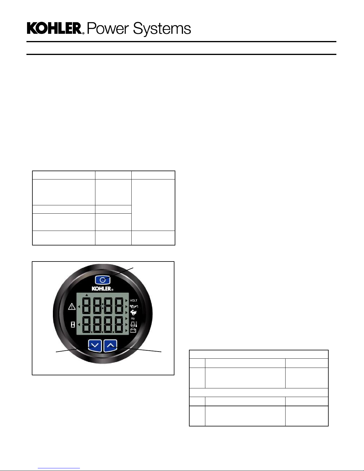
The digital gauge allows remote starting/stopping and
monitoring of certain generator set functions. The
three-inch remote digital gauge can be used with the
marine generator set models/controllers shown in
Figure 1. See Figure 2 for the remote digital gauge.
Model Controller Kit Number
EGD, EFGD, and EGZD
EOD and EFOD
EOZD and EFOZD
EKD and EFKD ADC II
EKOD and EFKOD
EKOZD and EFKOZD
EKOZD and EFKOZD
Figure 1 Kit Number for Model with Controller Type
ADC 2100
ADC IId
Decision-
Makerr 3500
GM32337-KP1
GM100956-KP1
1
Note: For generator sets with an ADC 2100
controller and with serial numbers below
2051416: These units used an earlier version of
the ADC 2100controller that was equipped witha
removeable power mode jumper at P7.
Operation of the remote digital gauge’s start/stop
function requires that the jumper is enabled on
the Advanced Digital Control (ADC) (generator
sets shipped from the factory already have the
jumper enabled). Refer to the wiring diagram in
the generator set operation manual if the jumper
was disconnected from terminals 1 and 2 on the
P7 connector (continuous power mode).
Note: For generator sets with an ADC 2100
controller: ADC application program version
3.32 or higher is required for complete digital
gauge operation. If your application program
version is lower than 3.32, use your SecurID to
access Kohler Power Resource Center, click on
the TechTools button, and follow the instructions
to download the files.
Note: For generator sets with a Decision-Makerr
3500 controller: Firmware version 1.14.3 or
higher is required for complete digital gauge
operation. If your firmware version is lower than
1.14.3, visit the Kohler Power Resource Center
website using the TechTools button.
1. SELECT button
2. UP arrow button
3. DOWN arrow button
Figure 2 Remote Digital Gauge
Parts List
Remote Digital Gauge Kits
23
Kit: GM32337-KP1
Qty. Description Part Number
1 Gauge GM100649
1 Harness, gauge GM32325
1 Decal, warning 249494
Kit: GM100956-KP1
Qty. Description Part Number
1 Gauge GM100649
1 Harness, gauge GM100955
1 Decal, warning 249494
Page 2
Safety Precautions
WARNING
Accidental starting.
Can cause severe injury or death.
Disconnect the battery cables before
working on the generator set.
Remove the negative (--) lead first
when disconnecting the battery.
Reconnect the negative (--) lead last
when reconnecting the battery.
Disabling the generator set. Accidental starting can
cause severe injury or death. Before working on the
generator set or connected equipment, disable the generator
set as follows: (1) Move the generator set master switch to the
OFF position. (2) Disconnect the power to the battery charger.
(3) Remove the battery cables, negative (--) lead first.
Reconnect the negative (--) lead last when reconnecting the
battery. Follow these precautions to prevent starting of the
generator set by an automatic transfer switch, remote
start/stop switch, or engine start command from a remote
computer.
Carbon monoxide symptoms. Carbon monoxide can
cause severe nausea, fainting, or death. Carbon monoxide
is a poisonous gas present in exhaust gases. Carbon
monoxide is an odorless, colorless, tasteless, nonirritating gas
that can cause death if inhaled for even a short time. Carbon
monoxide poisoning symptoms include but are not limited to
the following:
D Light-headedness, dizziness
D Physical fatigue, weakness in
joints and muscles
D Sleepiness, mental fatigue,
inability to concentrate
or speak clearly, blurred vision
D Stomachache, vomiting, nausea
If experiencing any of these symptoms and carbon monoxide
poisoning is possible, seek fresh air immediately and remain
active. Do not sit, lie down, or fall asleep. Alert others to the
possibility of carbon monoxide poisoning. Seek medical
attention if the condition of affected persons does not improve
within minutes of breathing fresh air.
Operating thegenerator set. Carbon monoxidecan cause
severe nausea, fainting, or death. Be especially careful if
operating the generator set when moored or anchored under
calm conditions because gases may accumulate. If operating
the generator set dockside, moor the craft so that the exhaust
discharges on the lee side (the side sheltered from the wind).
Always be aware of others, making sure your exhaust is
directed away from other boats and buildings.
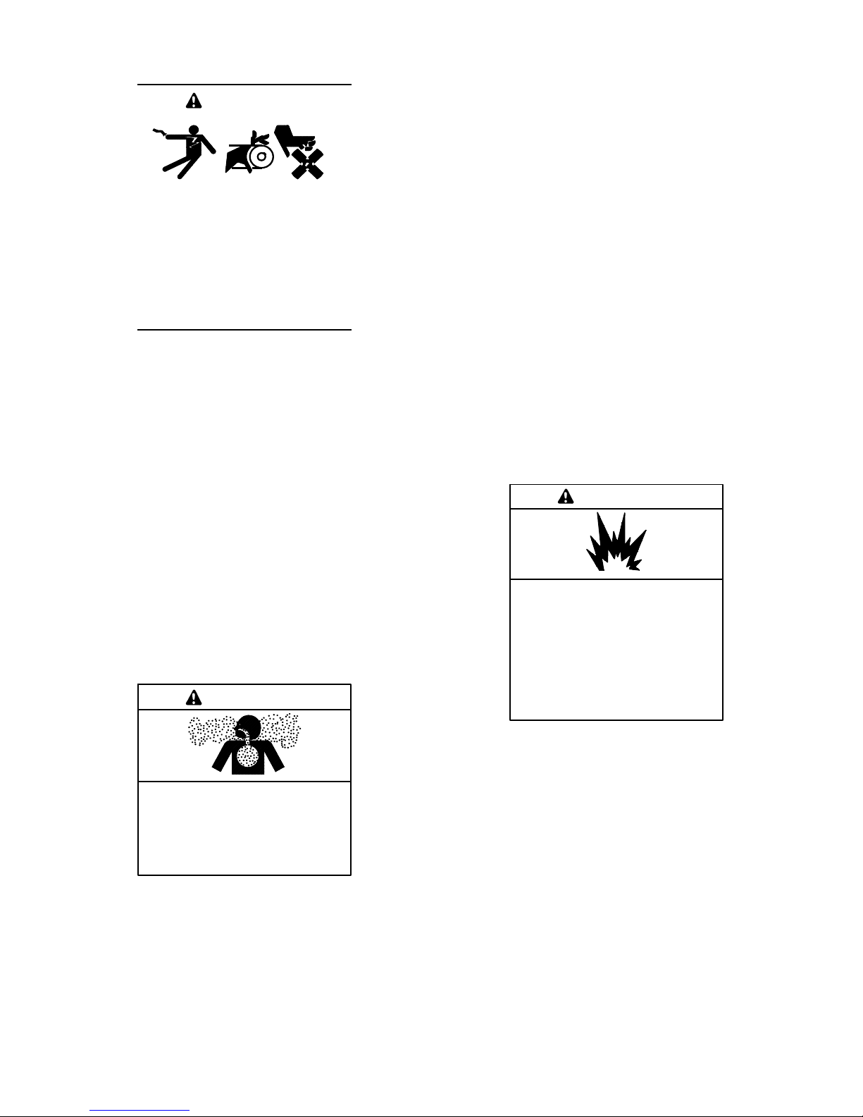
WARNING
Disabling the generator set. Accidental starting can
cause severe injury or death. Before working on the
generator set or equipment connected to the set, disable the
generator set as follows: (1) Press the generator set off/reset
button to shut down the generator set. (2) Disconnect the
power to the battery charger, if equipped. (3) Remove the
battery cables, negative (--) lead first. Reconnect the negative
(--) lead last when reconnecting the battery. Follow these
precautions to prevent the starting of the generator set by the
remote start/stop switch.
WARNING
Carbon monoxide.
Can cause severe nausea,
fainting, or death.
The exhaust system must be
leakproof and routinely inspected.
Explosion.
Gasoline vapors can cause
explosion and severe injury or
death.
Before starting the generator set,
operate the blower 4 minutes and
check the engine compartment for
gasoline vapors.
Ignition-protected equipment. Explosive fuel vapors can
cause severe injury or death. Gasoline vapors can cause an
explosion. USCG Regulation 33CFR183 requires that all
electrical devices (ship-to-shore transfer switch, remote start
panel, etc.) must be ignition protected when used in a gasoline
and gaseous-fueled environment.
2 TT-1379 5/16
Page 3
Installation Procedure
1. Remove the generator set from service.
1.1 For generator sets with an ADC 2100
controller: Place the generator set master
switch in the OFF position.
For generator sets with an ADC II or ADC IId
controller: Press the start/stop button to stop
the generator set. Then, press the power button
to turn off the controller.
For generator sets with a Decision-Makerr
3500 controller: Press the OFF/RESET button
to shut down the generator set.
1.2 Disconnect the generator set engine starting
battery, negative (--) lead first.
2. Install the remote digital gauge.
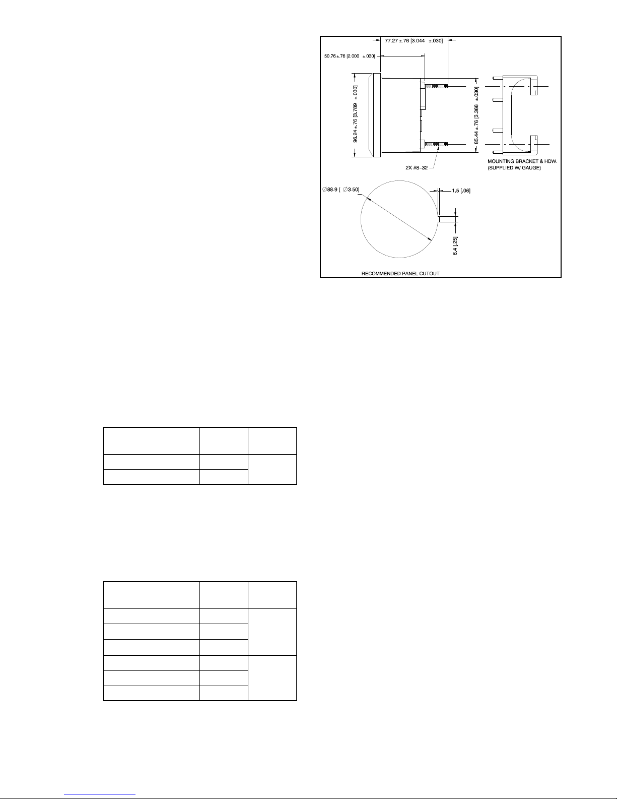
2.1 Select a dry location to mount the remote digital
gauge. Consider the length of the wiring
harness and the gauge’s mounting depth and
size when selecting a location. See Figure 5 for
the mounting dimensions.
2.2 For unitswith an ADCcontroller, ordera remote
extension harness kit. See Figure 3 for kit
selection. Do not use more than 3 remote
harness kits and do not exceed 23 m (75 ft.) in
harness length.
Remote Extension
Harness Kit Number
GM32333-KP1 4.6 (15)
GM32333-KP2 7.6 (25)
Figure 3 Remote Extension Harness Kits (For Units
with an ADC Controller)
For units with a Decision-Makerr 3500
controller, order a remote extension harness
kit. See Figure 4 for kit selection. DO NOT
exceed 91.4 m (300 ft.) CAN network length.
Length
m (ft.)AsShown In
Figure 8
NOTE: Dimensions in brackets
are inch equivalents.
GM30565-B
Figure 5 Mounting Dimensions
2.3 Connect the 6-pin inline connector of the gauge
harness (GM32325 or GM100955) to the 6-pin
inline connector on the digital gauge. See
Figure 6 and Figure 7 or Figure 10.
2.4 For Kit GM32337-KP1: Connect the 12-pin
connector end of the gauge harness or a remote
extension harness to the generator set’s
customer-interface 12-pin connector. See
Figure 7, Figure 8, and Figure 9.
2.5 For Kit GM100956-KP1: Connect the 6-pin
connector end of the gauge harness to a remote
extension harness. See Figure 10, Figure 11,
Figure 12, Figure 13, Figure 14, and Figure 15.
Connect the lead ends of the extension harness
to the TB12 terminal strip. The TB12 terminal
strip is located inside the junction box. See
Figure 15 for TB12 connections.
Remote Extension
Harness Kit Number*
GM91774-KP1 7.6 (25)
GM91774-KP2 15.2 (50)
GM91774-KP3 30.5 (100)
GM92053-KP1 7.6 (25)
GM92053-KP3 30.5 (100)
* Y Harness shown in Figure 13
Figure 4 Remote Extension Harness Kits (For Units
with a Decision-Makerr 3500 Controller)
TT-1379 5/16 3
Length
m (ft.)AsShown In
Figure 11
Figure 12GM92053-KP2 15.2 (50)
Page 4
Connects to the
remote harness.
Connects to
additional serial
gauges, if equipped.
NOTE: Dimensions in brackets are inch equivalents.
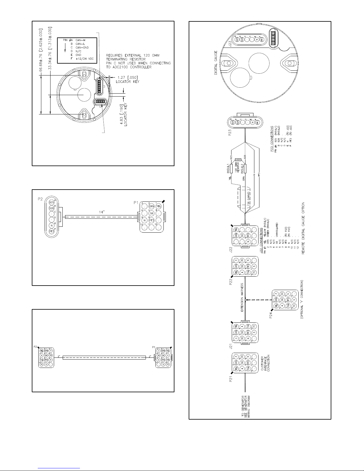
Figure 6 Remote Digital Gauge Connections
(Back View)
Connects to the
remote digital gauge
connector.
Connects to the
generator set
customer-interface
connector or
a remote harness
connector.
Figure 7 Remote Gauge Harness GM32325
(Included with Kit GM32337-KP1)
15 ft. Extension Harness Kit GM32333-KP1
25 ft. Extension Harness Kit GM32333-KP2
GM30565A-B
GM32325-F
Figure 8 Remote Extension Harness Kits
(For Use With Kit GM32337-KP1)
4 TT-1379 5/16
GM30248-
GM33846A-D
Figure 9 Harness Connection Diagram
For Kit GM32337-KP1
Page 5

25 ft. Extension Harness Kit GM92053-KP1
50 ft. Extension Harness Kit GM92053-KP2
100 ft. Extension Harness Kit GM92053-KP3
Connects to the
remote digital gauge
connector.
Connects to the
remote extension
harness connector.
Figure 10 Remote Gauge Harness GM100955
(Included with Kit GM100956-KP1)
25 ft. Extension Harness Kit GM91774-KP1
50 ft. Extension Harness Kit GM91774-KP2
100 ft. Extension Harness Kit GM91774-KP3
Figure 11 Remote Extension Harness Kits
(For Use With Kit GM100956-KP1)
GM100955-
GM100990-
GM100997
Figure 12 Remote Extension Harness Kits
(For Use With Kit GM100956-KP1)
Y Harness Kit GM92054-KP1
GM100996-
Figure 13 Y Harness Kit
(For Use With Kit GM100956-KP1)
Figure 14 Remote System Diagram For Kit GM100956-KP1
TT-1379 5/16 5
GM92060-A
Page 6

Sheet 1 of 2
Sheet 2 of 2
Figure 15 Interconnection Diagram For Kit GM100956-KP1
6 TT-1379 5/16
GM88254-B
Page 7

2.6 Use rubber grommets and cable ties as
necessary to protect and secure the wiring from
sharp objects, exhaust system, water, and any
moving parts.
2.7 For gasoline-powered marine generator
sets, select a location as near as practical to the
generator remote digital gauge for mounting the
warning decal. The decal should be visible when
starting the generator set from the remote digital
gauge. Before applying the decal, ensure that
the surface is clean and dry.
3. Restore the generator set to service.
3.1 Check that the generator set is off and stopped.
3.2 Reconnect the generator set engine starting
battery, negative (--) lead last.
4. Set the controller parameter for J1939
communications.
4.1 For generator sets with an ADC 2100
controller: Set the ADC 2100 controller’s
communication parameter to Cn01 or Cn06.
Consult TT-1364 for instructions to change the
controller’s parameter settings.
For generator sets with a Decision-Makerr
3500 controller: Using SiteTecht, under the
Genset System Configuration menu, select
J1939 for the Public CAN Protocol parameter.
See Figure 16.
Note: For more information on SiteTecht,see
TP-6701t SiteTech Software Operation
Manual.
Note: ADC 2100 controllers: When the
master switch is in the AUTO position,
the controller may automatically power
down and go into Sleep Mode to
conserve battery power. This will occur,
after one hour of inactivity, only when the
CAN parameter is set to Cn06. If the
CAN parameter is set to Cn01, the
controller will remain powered and will
draw battery power. See TT-1364 for
more information.
ADC 2100 Controller
CAN
Setting
Cn01 Never/None J1939 gauge with
Cn06 1 Hour J1939 gauge with
Power
Down Time
Application
Notes
no sleep mode
one hour sleep
mode
For generator sets with an ADC II controller:
Set the CAN A parameter to J1939. Consult the
generator set installation manual for full
instructions to set the CAN A parameter.
Figure 16 Genset System Configuration (in SiteT echt)
For generator sets with an ADC IId controller:
Set the CAN A parameter, under the Gen Set
System menu, to J1939. Consult the generator
set operation manual for full instructions to set
the CAN A parameter.
TT-1379 5/16 7
Page 8

Gauge Operation
To Select the Units of Measure:
Note: Data can be displayed in either US or
international units.
1. With no power to the gauge, press and hold the
SELECT button. See Figure 17.
2. Apply power to the gauge.
3. The gauge displays: Adc 2100
Note: The gauge will display Adc 2100 even if
the generator set is equipped with an
ADC II or ADC IId controller.
4. The gauge displays: UnIT SEt
5. Press and hold both the UP and DOWN buttons
until the gauge beeps and the display changes.
6. Use the UP or DOWN buttons to selecteither Int or
USA units.
7. Press and hold both the UP and DOWN buttons
until the gauge beeps and the display changes.
8. Press the DOWN button.
21
!
GM30565-B
10
1. Fault indicator
2. Arrow (if blinking, indicates that the generator set is running)
3. Select button
4. Voltage (volts)
5. Oil pressure (psi or kPa)
6. Engine speed (rpm)
7. Frequency (Hz)
8. Coolant temperature (_For_C)
9. Battery voltage (VDC)
10. Runtime hours
Figure 17 Remote Digital Gauge
3
4
5
6
7
8
9
9. The gauge displays: ESC 08 ?
10. Press and hold both the UP and DOWN buttons
until the gauge switches to the monitor mode.
8 TT-1379 5/16
Page 9

Digital Gauge Modes:
Start/Stop Command Mode
Note: The digital gauge has three normal operating
modes: monitor, start/stop, and backlight adjust.
Use the SELECT button at the top of the gauge to
step through the modes.
Monitor Mode
Press the SELECT button until the display shows
generator set data and indicator arrows. Use the UP or
DOWN arrow to scroll through the data. The
corresponding illuminated arrow indicates which data is
being displayed. See Figure 17. Any faults are
displayed in blinking text. The following generator set
operation data is displayed in this mode:
D Voltage (AC volts)
D Oil pressure (psi or kPa). May require the
installation of an optional oil pressure
sender on the engine. See Figure 18.
D Engine speed (rpm)
D Frequency (Hz)
D Coolant temperature (_For_C)
D Runtime hours
D Battery voltage (VDC)
Note: The maximum battery voltage that the
ADC will display on the remote digital
gauge is 31.5 volts. If the voltage is
higher than 31.5, it will display 31.5 volts.
Model Oil Pressure Sender
EKD and EFKD
EOD and EFOD
EOZD and EFOZD
EGD, EFGD, and EGZD
EKOZD and EFKOZD
Figure 18 Models with Optional or Standard
Oil Pressure Sender
Optional
StandardEKOD and EFKOD
Press the SELECT button until the display shows SEND
RUN or SEND STOP. Use the UP or DOWN arrow to
send a remote start/stop command.
Note: The ADC 2100 must be powered (display active)
and the master switch must be in the AUTO
position for remote start/stop. If the ADC 2100
master switch is in the RUN position, a remote
stop command will not stop the generator set.
The arrow at the top left side of the display blinks
to indicate that the generator set is running (see
Figure 17, item 2).
Note: The ADC II and ADC IId must be powered
(display active) for remote start/stop.
Note: The Decision-Maker 3500 must be powered
(display active) and in the AUTO position for
remote start/stop. If in the RUN position, a
remote stop command will not stop the generator
set. The arrow at the top left side of the display
blinks to indicate that the generator set is running
(see Figure 17, item 2).
Refer to the generator set operation manual and follow
the safety precautions when operating the generator
set.
Backlighting Mode
Press the SELECT button until the display shows LEVL.
Use the UP or DOWN arrow to select a lighting level:
D 0 = no backlight
D 3 = brightest backlight.
Note: While in this mode, faults appear on the display,
however no audible alarm is heard.
Once set, the backlight level defaults to the last
selection.
The maximumpower draw of the remote gauge is50 mA
at 12 VDC (or 25 mA at 24 VDC) with the brightest
backlight.
TT-1379 5/16 9
To Silence an Audible Alarm:
Faults are indicated by blinking or solid text and an
audible alarm. To silence an audible alarm, press and
hold the UP and DOWN arrow buttons simultaneously
until the gauge emits a long beep and then release.
Note: For a fault warning, the background lamp is solid.
For a fault shutdown, the background lamp will
flash. Consult your operation manual for more
details on warnings and shutdowns.
Page 10

Note: Always identify and correct the cause of a fault
shutdown before resetting the controller. Consult
the operation manual for guidance and items to
check.
Digital Gauge Fault Codes
Fault codes are displayed on the gauge when a fault
condition is detected.
See Figure 19 for faults displayed on the gauge for units
equipped with an ADC 2100 controller.
See Figure 20 for faults displayed on the gauge for units
equipped with an ADC II or ADC IId controller.
See Figure 21 for faults displayed on the gauge for units
equipped with a Decision-Makerr 3500 controller.
Units with ADC 2100 Controller
Digital Gauge
Display
LOP Low Oil Pressure
OC Over Crank
OS Over Speed
LCL Low Coolant Level
LOC Loss of Coolant
AF Auxiliary Input Fault
HE High Engine Temperature
OU Over Voltage
UU Under Voltage
OF Over Frequency
UF Under Frequency
LB Low Battery Voltage
HB High Battery Voltage
Figure 19 Fault Codes Displayed on the Gauge (for
Units Equipped with an ADC 2100
Controller)
Description
Units with ADC II or ADC IId Controller
Digital Gauge
Display
LOP Low Oil Pressure
OC Over Crank
OS Over Speed
AF Auxiliary Input Fault
HE High Engine Temperature
OU Over Voltage
UU Under Voltage
OF Over Frequency
UF Under Frequency
LB Low Battery Voltage
HB High Battery Voltage
Description
Figure 20 Fault Codes Displayed on the Gauge (for
Units Equipped with an ADC II or ADC IId
Controller)
Units with Decision-Makerr 3500 Controller
Digital Gauge
Display
LOP Low Oil Pressure
OS Over Speed
AF Auxiliary Input Fault
HE High Engine Temperature
OU Over Voltage
UU Under Voltage
OF Over Frequency
UF Under Frequency
For other possible fault codes, the gauge displays:
SHdn (for a Shutdown) or
Alrt (for an Alert/Warning).
Check the interface on the Decision-Makerr 3500 Controller for more
details.
Description
Figure 21 Fault Codes Displayed on the Gauge (for
Units Equipped with an Decision-Makerr
3500 Controller)
10 TT-1379 5/16
Page 11

Notes
TT-1379 5/16 11
Page 12

KOHLER CO., Kohler, Wisconsin 53044 USA
Phone 920-457-4441, Fax 920-459-1646
For the nearest sales and service outlet in the
US and Canada, phone 1-800-544-2444
KOHLERPower.com
Kohler Power Systems
Asia Pacific Headquarters
7 Jurong Pier Road
Singapore 619159
Phone (65) 6264-6422, Fax (65) 6264-6455
Availability is subject to change without notice. Kohler Co. reserves the
right tochange the design or specifications without noticeand withoutany
obligation or liability whatsoever. Contact your local Kohlerr generator
set distributor for availability.
2004, 2006, 2012, and 2016 by Kohler Co. All rights reserved.
12 TT-1379 5/16
 Loading...