

Page 1
Original Issue Date: 7/04
Model: 6EKOD/5EFKOD, 9--11EKOZD/7--9EFKOZD, and
8--32EOZD/6.5--27EFOZD
Market: Marine
Subject: Fuel/Water Separator Kit GM31994-KP1
TT-1375 4/12a
INSTALLATION INSTRUCTIONS
Introduction
The marine generator set models shown in Figure 1
require a fuel/water separator located between the fuel
tank and the electric fuel pump. The fuel/water
separator kit helps to remove water and sediment from
the fuel system. After the kit is installed, verify that all
connections are tight.
6EKOD/5EFKOD
9EKOZD/7EFKOZD
11EKOZD/9EFKOZD
8EOZD/6.5EFOZD
9EOZD/7EFOZD
10EOZD/8.5EFOZD
10EOZD/9EFOZD
13EOZD/11EFOZD
14EOZD/11.5EFOZD
15EOZD/13EFOZD
15.5EOZD/13EFOZD
20EOZD/17EFOZD
20EOZD/17.5EFOZD
23EOZD/20EFOZD
24EOZD/20EFOZD
28EOZD/25EFOZD
32EOZD/28EFOZD
Figure 1 Marine Models Requiring a Fuel/Water
Separator
Fuel/Water Separator Kit
Kit: GM31994-KP1
Qty. Description Part No.
1 Filter, fuel/water separator GM41013
Safety Precautions
Observe the following safety precautions while installing
the kit.
WARNING
Accidental starting.
Can cause severe injury or death.
Disconnect the battery cables before
working on the generator set.
Remove the negative (--) lead first
when disconnecting the battery.
Reconnect the negative (--) lead last
when reconnecting the battery.
Disabling the generator set. Accidental starting can
cause severe injury or death. Before working on the
generator set or connected equipment, disable the generator
set as follows: (1) Move the generator set master switch to the
OFF position. (2) Disconnect the power to the battery charger.
(3) Remove the battery cables, negative (--) lead first.
Reconnect the negative (--) lead last when reconnecting the
battery. Follow these precautions to prevent starting of the
generator set by an automatic transfer switch, remote
start/stop switch, or engine start command from a remote
computer.
Installation Procedure
1. Remove the generator set from service.
1.1 Place the generator set master switch in the OFF
position.
1.2 Disconnect the generator set engine starting
battery(ies), negative (--) lead first.
Page 2
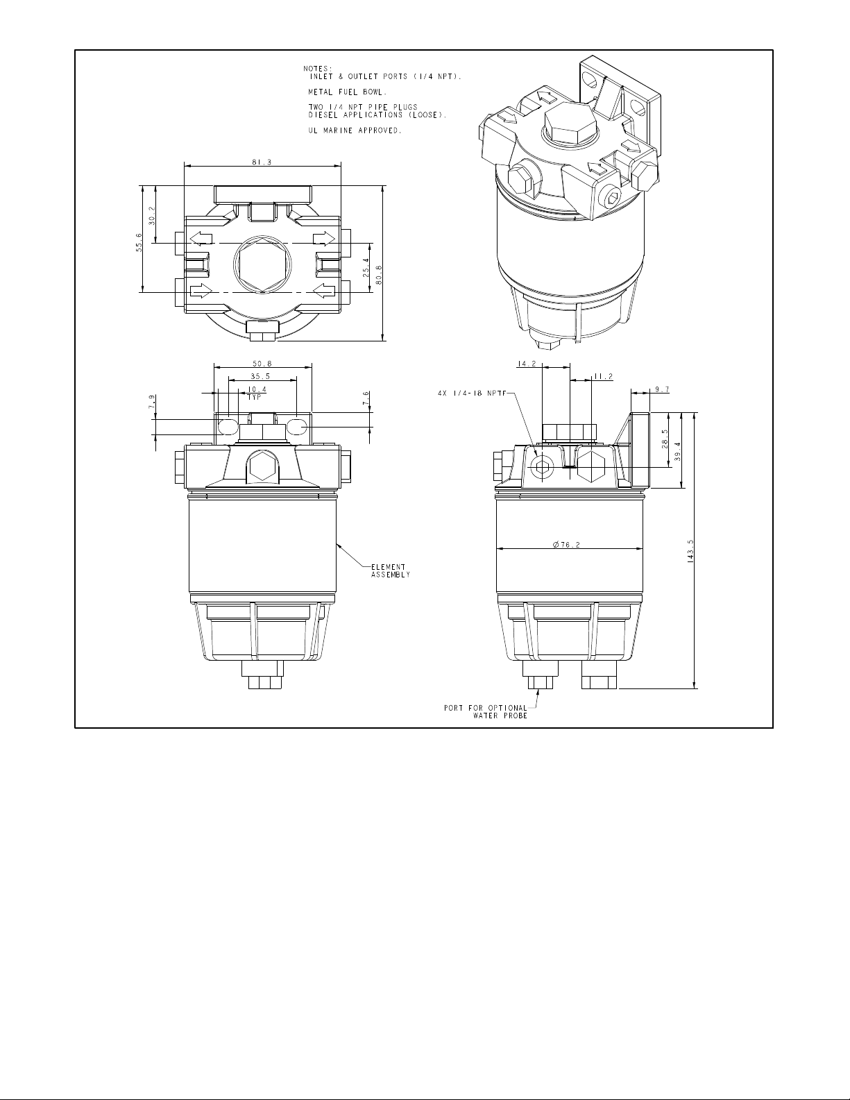
Dimensions are shown in millimeter (mm).
Figure 2 Fuel/Water Separator Dimensions for Mounting
GM32181-E
2. Install the fuel/water separator.
2.4 Connect the fuel line from the fuel tank to the inlet
side of the fuel/water separator. Secure the fuel
Note: Apply thread sealant to the male threaded
line with two hose clamps, one on each end.
fuel connections.
2.5 Insert the pipe plugs (supplied with the kit) into the
2.1 Disconnect the customer-supplied fuel lines that
fuel/water separator’s unused ports.
run from the fuel tank to the generator set.
2.2 Mount the fuel/water separator (GM41013) to the
bulkhead.
2.3 Connect a flexible fuel line from the outlet side of
the fuel/water separator to the inlet side of the fuel
pump. Secure the fuel line with two hose clamps,
one on each end.
2 TT-1375 4/12
3. Restore the generator set to service.
3.1 Check that the generator set master switch is in
the OFF position.
3.2 Reconnect the generator set engine starting
battery, negative (--) lead last.
Page 3

Note: Bleed the fuel system according to the
generator set operation manual. If air is
trapped in the fuel system, the engine will
be difficult to start and/or engine operation
will be erratic.
5. Changing the element.
At the interval specified in the generator set operation
manual, replace the water separator element using the
following procedure.
4. Draining the water.
At the interval specified in the generator set operation
manual, drain water from the fuel/water separator. Hold
a suitable container beneath the fuel/water separator
and push up on the drain valve. See Figure 3. Release
the valve when fuel (free of water) flows from the
fuel/water separator.
1
2
3
5.1 Close the fuel valve at the nearest point to the
water filter inlet or at the fuel tank.
5.2 Remove the water drain plug (or push up the drain
valve) and allow water and fuel to flow into a
suitable c ontainer.
Note: Depending upon the location of the fuel valve, a
considerable amount of fuel may drain out.
5.3 Remove the water separator element from the
mounting head by twisting in a counterclockwise
direction.
5.4 Remove the bowl from the fuel/water separator
element. Wipe the excess fuel from the bowl and
the O-ring. Do not discard the bowl or O-ring.
5.5 Inspect the components for wear or damage.
Replace parts as necessary.
5.6 Lubricate the O-ring with clean diesel fuel and
replace i t in the bowl.
5.7 Install the bowl onto a new fuel/water separator
filter element.
1. Air bleed screw
2. Drain plug
3. Drain valve
Figure 3 Fuel/Water Separator
GM32181
Note: Kohler service replacement fuel/water separator
element part number is GM41014.
5.8 Lubricate the bowl/element assembly with clean
fuel. Install the bowl/element onto the filter
mounting head.
5.9 Replace the water drain plug (if removed) and
close the vent.
5.10 Remove the air bleed screw from the fuel/water
separator.
5.11 Open the fuel supply valve.
5.12 After fuel fills the water separator, allow fuel to flow
from the air bleed hole until all air is displaced (fuel
flows free of air bubbles).
5.13 Replace the air bleed screw.
TT-1375 4/12 3
Page 4

Notes
4 TT-1375 4/12
 Loading...