

Page 1
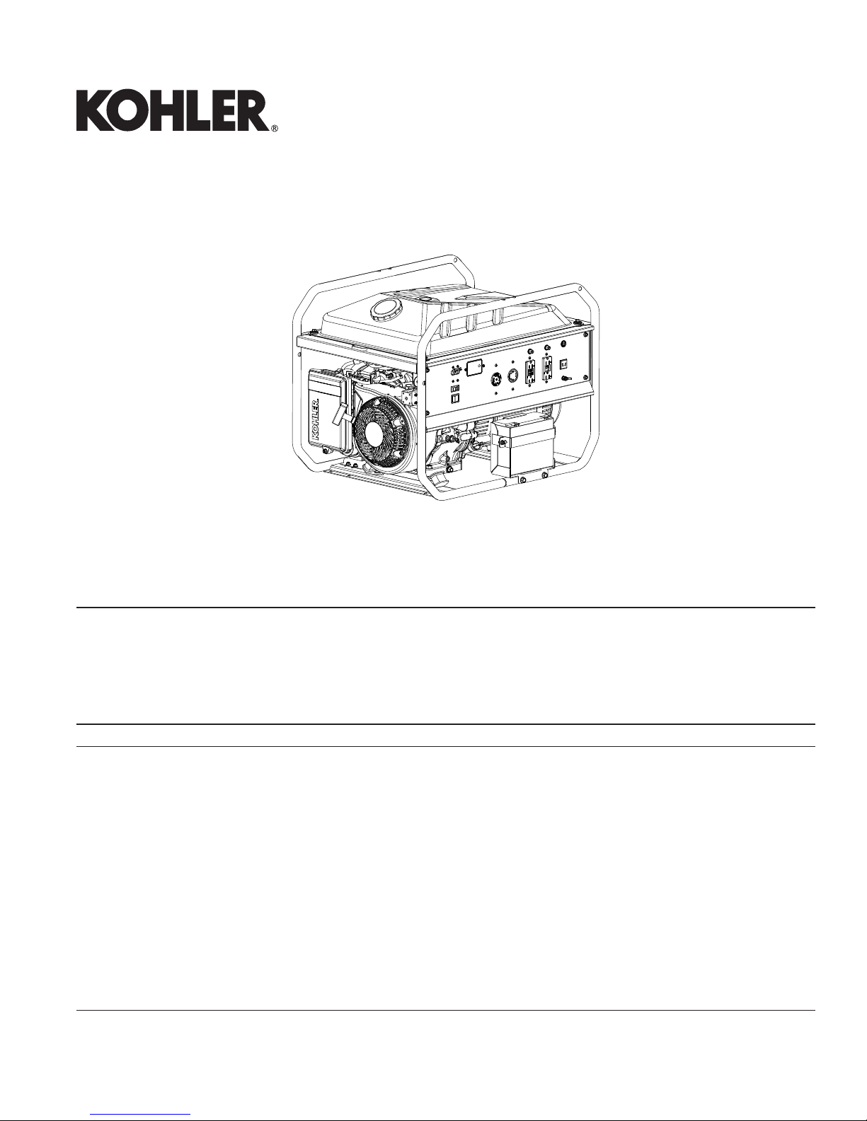
PRO 5.2, PRO 5.2 E, PRO 7.5, PRO 7.5 E
Generator Service Manual
IMPORTANT: Read all safety precautions and instructions carefully before operating equipment. Refer to operating
instruction of equipment that this engine powers.
Ensure engine is stopped and level before performing any maintenance or service.
For all engine related maintenance, disassembly and reassembly, refer to service manual of engine
powering this equipment.
2 Safety
3 Specifi cations
6 Troubleshooting
9 Electrical System
14 Disassembly/Inspection and Service
16 Reassembly
KohlerPower.com37 690 01 Rev. --
1
Page 2

Safety
SAFETY PRECAUTIONS
WARNING: A hazard that could result in death, serious injury, or substantial property damage.
CAUTION: A hazard that could result in minor personal injury or property damage.
NOTE: is used to notify people of important installation, operation, or maintenance information.
WARNING
WARNING
Explosive Fuel can
cause fi res and severe
burns.
Do not fi ll fuel tank while
engine is hot or running.
Gasoline is extremely fl ammable
and its vapors can explode
if ignited. Never refuel while
smoking or in vicinity of an open
fl ame. Store gasoline only in
approved containers, in well
ventilated, unoccupied buildings,
away from sparks or fl ames.
Spilled fuel could ignite if it comes
in contact with hot parts or sparks
from ignition. Never use gasoline
as a cleaning agent.
WARNING
Rotating Parts can cause
severe injury.
Stay away while
generator is in operation.
Keep hands, feet, hair, and
clothing away from all moving
parts to prevent injury. Never
operate generator with covers,
shrouds, or guards removed.
WARNING
Carbon Monoxide can
cause severe nausea,
fainting or death.
Avoid inhaling exhaust
fumes.
Engine exhaust gases contain
poisonous carbon monoxide.
Carbon monoxide is odorless,
colorless, and can cause death if
inhaled.
Accidental Starts can
cause severe injury or
death.
Disconnect and ground
spark plug lead(s) before
servicing.
Before working on engine or
equipment, disable engine as
follows: 1) Disconnect spark plug
lead(s). 2) Disconnect negative (–)
battery cable from battery.
Do not allow children to operate
generator.
Hot Parts can cause
severe burns.
Do not touch generator
while operating or just
after stopping.
Never operate generator with heat
shields or guards removed. Do not
modify generator.
Place generator in a place where
pedestrians or children are not
likely to touch generator.
Be sure to carry generator only by
its carrying handles.
Cleaning Solvents can
cause severe injury or
death.
Use only in well
ventilated areas away
from ignition sources.
Carburetor cleaners and solvents
are extremely fl ammable. Follow
cleaner manufacturer’s warnings
and instructions on its proper and
safe use. Never use gasoline as a
cleaning agent.
WARNING
WARNING
Electrical Shock can
cause injury.
Do not touch wires while
engine is running.
Never operate generator in rain or
snow.
Never touch generator with wet
hands or electrical shock may
occur.
Hazardous Voltage.
Backfeed to utility system
can cause property
damage, severe injury, or
death.
Never plug a portable generator
directly into a building outlet.
If generator is used for standby
power, have a certifi ed, licensed
electrician install an automatic
transfer switch to prevent
inadvertent interconnection of
standby and normal sources of
supply.
CAUTION
CAUTION
2 37 690 01 Rev. --KohlerPower.com
Page 3
Specifi cations
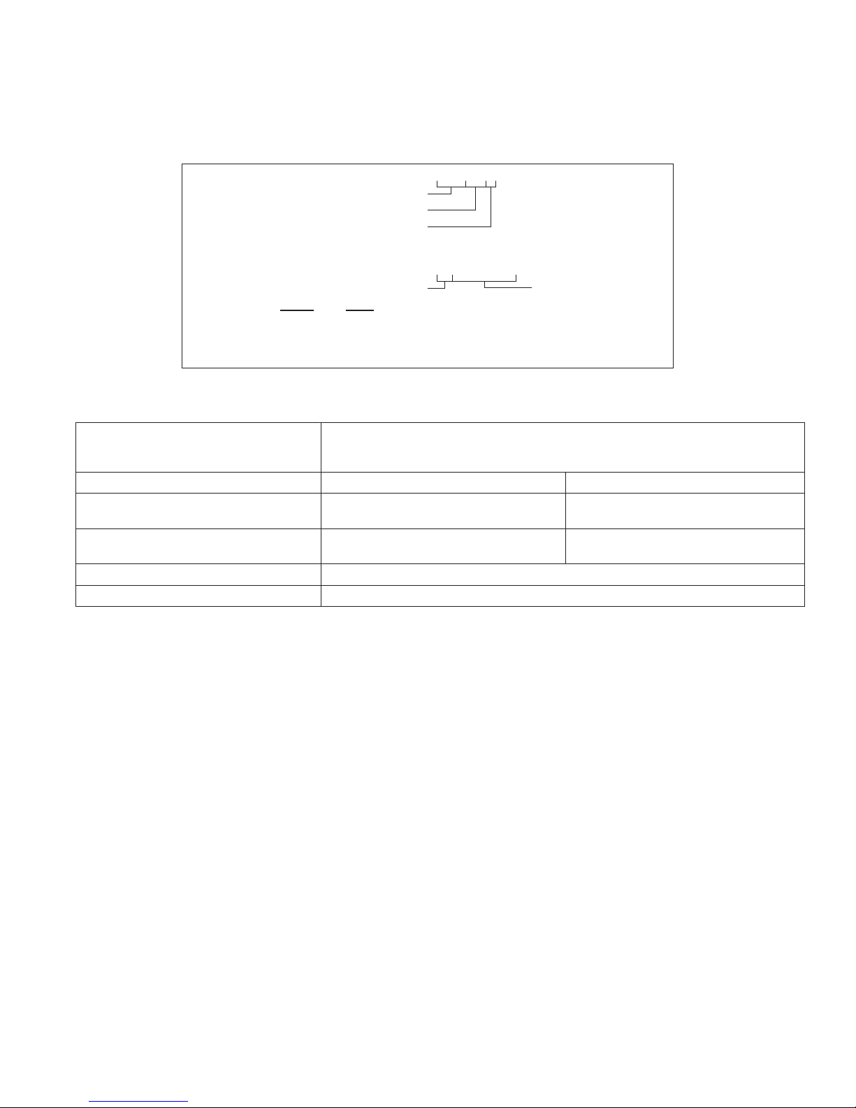
ENGINE IDENTIFICATION NUMBERS
Kohler engine identifi cation numbers (model, specifi cation and serial) should be referenced for effi cient repair,
ordering correct parts, and engine replacement.
Model . . . . . . . . . . . . . . . . . . . . . PRO5.2E
PRO
Numerical Designation
Optional
Specifi cation . . . . . . . . . . . . . . . PA-PRO52E-3001
Serial . . . . . . . . . . . . . . . . . . . . . 4323500328
Year Manufactured Code Factory Code
Code Year
43 2013
44 2014
45 2015
SPECIFICATIONS PRO 5.2/PRO 5.2 E PRO 7.5/PRO 7.5 E
Overall Dimensions (L x W x H) 670 mm (26.4 in.)
545 mm (21.5 in.)
535 mm (21.1 in.)
Dry Weight 76 kg (168 lbs.)/86 kg (189 lbs.) 90 kg (199 lbs.)/100 kg (220 lbs.)
AC Rated Power
AC Surge Power
DC Rated Power 100 Watt (12 Volts x 8.3 Amps)
Fuel Tank 30.2 L (8 gal.)
4500 Watt
5200 Watt
(120 Volts x 37.5 Amps)
(240 Volts x 18.8 Amps)
(120 Volts x 43.3 Amps)
(240 Volts x21.7 Amps)
6300 Watt
7500 Watt
(120 Volts x 52.5 Amps)
(240 Volts x 26.3 Amps)
(120 Volts x 62.5 Amps)
(240 Volts x 31.3 Amps)
337 690 01 Rev. -- KohlerPower.com
Page 4

Specifi cations
TORQUE SPECIFICATIONS
3
Alternator Front Cover 53.5 N·m (474 in. lb.)
Alternator Rear Cover 4.5 N·m (40 in. lb.)
AVR and Brush Assembly 4.0 N·m (35 in. lb.)
Battery Mounting Bracket
M6 Screws
M8 Screws
9.9 N·m (87 in. lb.)
25.0 N·m (221 in. lb.)
Carbon Canister Mounting Bracket 9.9 N·m (87 in. lb.)
Control Panel Back Cover 5.8 N·m (51 in. lb.)
Control Panel Electrical Components
M3 Screws
M4 Screws
1.3 N·m (11 in. lb.)
2.9 N·m (26 in. lb.)
Control Panel 9.9 N·m (87 in. lb.)
Engine/Alternator Isolators 18.3 N·m (162 in. lb.)
Frame Assembly
M6 Screws
M10 Screws
11.5 N·m (102 in. lb.)
30.0 N·m (266 in. lb.)
Fuel Tank Mounting 9.9 N·m (87 in. lb.)
Muffl er Assembly
M8 Screws
M10 Screws
Muffl er Cover Assembly
Rotor Assembly
Stator Assembly
Wire Connector
25.0 N·m (221 in. lb.)
32.5 N·m (288 in. lb.)
9.9 N·m (87 in. lb.)
22.0 N·m (195 in. lb.)
10.4 N·m (92 in. lb.)
2.5 N·m (22 in. lb.)
3
Values are in Metric units. Values in parentheses are English equivalents.
4 37 690 01 Rev. --KohlerPower.com
Page 5
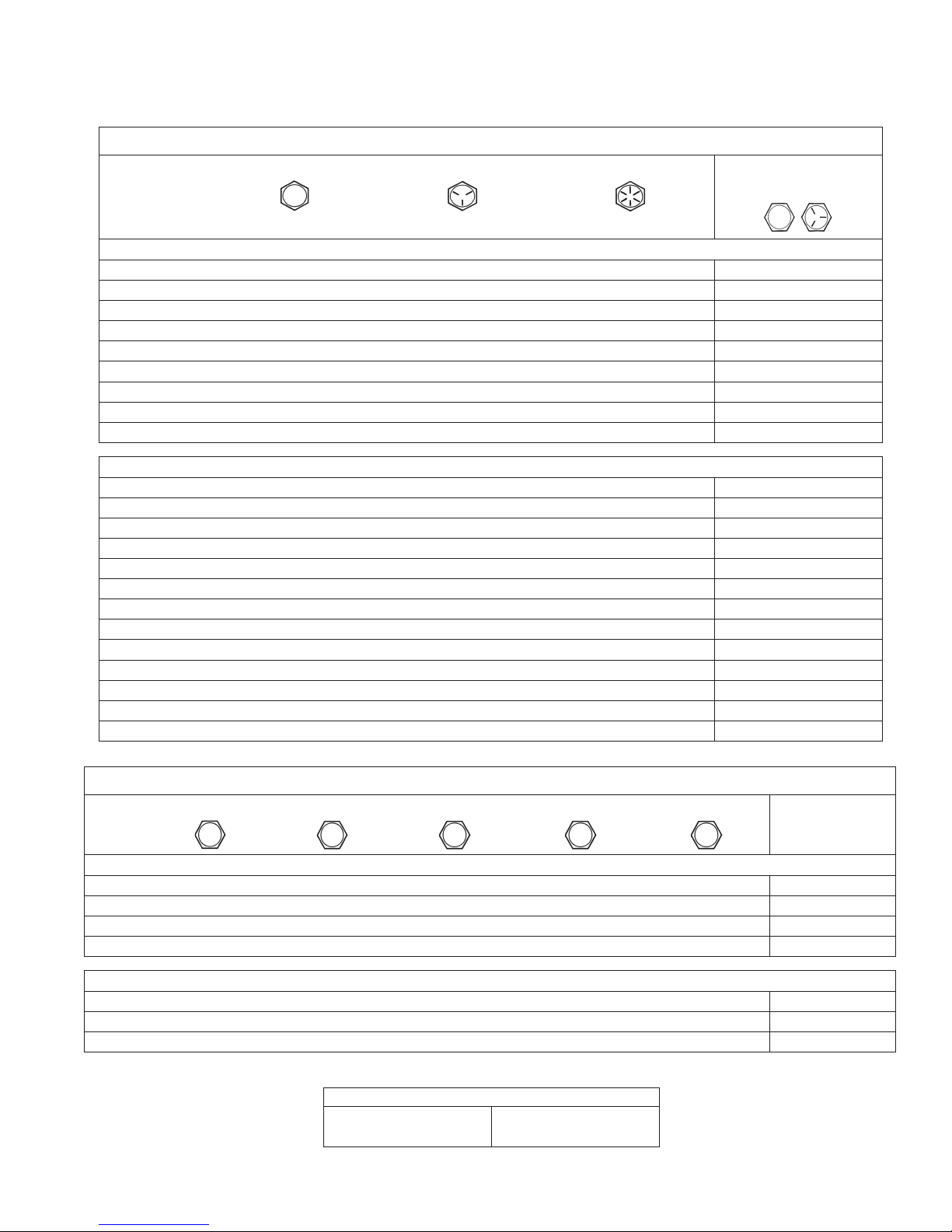
GENERAL TORQUE VALUES
English Fastener Torque Recommendations for Standard Applications
Bolts, Screws, Nuts and Fasteners Assembled Into Cast Iron or Steel
Grade 2 or 5 Fasteners
Size Grade 2 Grade 5 Grade 8
Tightening Torque: N·m (in. lb.) ± 20%
8-32 2.3 (20) 2.8 (25) — 2.3 (20)
10-24 3.6 (32) 4.5 (40) — 3.6 (32)
10-32 3.6 (32) 4.5 (40) — —
1/4-20 7.9 (70) 13.0 (115) 18.7 (165) 7.9 (70)
1/4-28 9.6 (85) 15.8 (140) 22.6 (200) —
5/16-18 17.0 (150) 28.3 (250) 39.6 (350) 17.0 (150)
5/16-24 18.7 (165) 30.5 (270) — —
3/8-16 29.4 (260) — — —
3/8-24 33.9 (300) — — —
Tightening Torque: N·m (ft. lb.) ± 20%
5/16-24 — — 40.7 (30) —
3/8-16 — 47.5 (35) 67.8 (50) —
3/8-24 — 54.2 (40) 81.4 (60) —
7/16-14 47.5 (35) 74.6 (55) 108.5 (80) —
7/16-20 61.0 (45) 101.7 (75) 142.5 (105) —
1/2-13 67.8 (50) 108.5 (80) 155.9 (115) —
1/2-20 94.9 (70) 142.4 (105) 223.7 (165) —
9/16-12 101.7 (75) 169.5 (125) 237.3 (175) —
9/16-18 135.6 (100) 223.7 (165) 311.9 (230) —
5/8-11 149.5 (110) 244.1 (180) 352.6 (260) —
5/8-18 189.8 (140) 311.9 (230) 447.5 (330) —
3/4-10 199.3 (147) 332.2 (245) 474.6 (350) —
3/4-16 271.2 (200) 440.7 (325) 637.3 (470) —
Specifi cations
Into Aluminum
Metric Fastener Torque Recommendations for Standard Applications
Size
4.8
Tightening Torque: N·m (in. lb.) ± 10%
M4 1.2 (11) 1.7 (15) 2.9 (26) 4.1 (36) 5.0 (44) 2.0 (18)
M5 2.5 (22) 3.2 (28) 5.8 (51) 8.1 (72) 9.7 (86) 4.0 (35)
M6 4.3 (38) 5.7 (50) 9.9 (88) 14.0 (124) 16.5 (146) 6.8 (60)
M8 10.5 (93) 13.6 (120) 24.4 (216) 33.9 (300) 40.7 (360) 17.0 (150)
Tightening Torque: N·m (ft. lb.) ± 10%
M10 21.7 (16) 27.1 (20) 47.5 (35) 66.4 (49) 81.4 (60) 33.9 (25)
M12 36.6 (27) 47.5 (35) 82.7 (61) 116.6 (86) 139.7 (103) 61.0 (45)
M14 58.3 (43) 76.4 (56) 131.5 (97) 184.4 (136) 219.7 (162) 94.9 (70)
Property Class
5.8
8.8
10.9 12.9
Torque Conversions
N·m = in. lb. x 0.113 in. lb. = N·m x 8.85
N·m = ft. lb. x 1.356 ft. lb. = N·m x 0.737
Noncritical
Fasteners
Into Aluminum
537 690 01 Rev. -- KohlerPower.com
Page 6

Troubleshooting
TROUBLESHOOTING GUIDE
When troubles occur, be sure to check simple causes which, at fi rst, may seem too obvious to be considered. For
example, a starting problem could be caused by an empty fuel tank.
Some general common causes of engine troubles are listed below and vary by engine specifi cation. Use these to
locate causing factors.
Condition Possible Cause Solution
No AC output Circuit breaker in OFF position. Switch circuit breaker to ON.
Circuit protector popped out. Press circuit protectors.
Engine not operating at rated RPM. Adjust engine running at normal operating
temperature to 3750 ± 100 RPM.
Circuit breaker or receptacles faulty. Test for voltage at circuit breaker and
receptacles.
Stator is faulty. Test for voltage and resistance.
Brushes are faulty. Test for resistance between brushes and
slip ring.
AVR is faulty. Test for voltage.
Low voltage at stator Field polarity was lost. Flash rotor fi eld.
Alternator can't output
rated power
Tests
Stator voltage
Engine not operating at rated RPM. Adjust engine running at normal operating
temperature to 3750 ± 100 RPM.
Overload condition. Calculate electrical power required by
electric appliances (in Watts). Reduce
total wattage of connected electric devices
within application range.
Appliance is faulty. Repair faulty appliance.
6 37 690 01 Rev. --KohlerPower.com
Remove rear cover and start engine with
no load. Check if stator terminals have
correct voltage.
Page 7

Stator resistance
Troubleshooting
With engine stopped, check main coil
stator winding resistance between wires
with ohmmeter or circuit tester. Replace if
out of specifi cation.
With engine stopped, check exciting coil
stator winding resistance between wires
with ohmmeter or circuit tester. Replace if
out of specifi cation.
Brush resistance
Flashing Field
With engine stopped, remove brush.
Check brush and slip ring of rotor for
resistance. Replace if out of specifi cation.
With engine stopped, momentarily touch
the brush terminals with leads from a good
12 volt battery.
737 690 01 Rev. -- KohlerPower.com
Page 8

Troubleshooting
Replace AVR
With engine stopped, replace AVR with a
new AVR. Start engine and adjust trimmer
on back of AVR. Test terminal voltage.
Voltage should be between 95-135V. If
voltage is met, original AVR is not adjusted
properly or faulty. Replace as necessary. If
voltage not met, check circuit breakers and
receptacles.
Unit Item
Main Winding
Field Winding Between slip ring 47.9Ω±10% 46.6Ω±10% 56.4Ω±10%
Exciter Winding Blue-Blue 1.30Ω±10% 1.60Ω±10% 1.02Ω±10%
DC Winding Orange-Orange - 0.10Ω±10% 0.08Ω±10%
Brush Length 9mm
NOTE: Alternator should not be in contact with panel, AVR, etc during above resistance tests. Alternator should be
tested at room temperature.
Red-Blue 0.37Ω±10% 0.27Ω±10% 0.13Ω±10%
White-Black 0.37Ω±10% 0.27Ω±10% 0.13Ω±10%
GEN 5.0 PRO5.2/5.2E PRO7.5/7.5E
Generator Spec.
REMARK
Red-White
(PRO 7.5 E)
Service limit:
5mm
8 37 690 01 Rev. --KohlerPower.com
Page 9

PRO 5.2 Wiring Diagram
Electrical System
F
F
BA
E
C
D
O
N
G
K
K
H
J
I
J
I
L
M
P Q
A Main Winding 1 B Main Winding 2 C Exciter Field Coil D Sub Coil
E Voltage Selector F Circuit Breaker G
I GFCI Receptacle J Circuit Protector 20A K Circuit Protector 30A L Ground Terminal
M Engine Switch N Maintenance Minder O AVR P Oil Sentry
Q Spark Plug R Ignition Module
240/120V/30A
Electrical Socket
R
H
120V/30A
Electrical Socket
™
937 690 01 Rev. -- KohlerPower.com
Page 10

Electrical System
PRO 5.2 E Wiring Diagram
H
BA
C
D
E
U
F
T
AD
G
S
AB
AC
H
I
M
Z
M
J
R
V
W
Y
L
K
L
L
K
N
O
P
Q
X
AA
A Main Winding 1 B Main Winding 2 C Exciter Field Coil D Sub Coil
E DC Winding F Auto Idle Coil G Voltage Selector H Circuit Breaker
I
M Circuit Protector 30A N Ground Terminal O Auto Throttle Switch P 12V DC Receptacle
Q On/Off/Start Switch R Auto Idle Module S Maintenance Minder T AVR
U Rectifi er V Diode W Battery Fuse X Starter Motor
Y 12 Volt Battery Z Stator AA
AC Spark Plug AD Oil Sentry
240/120V/30A
Electrical Socket
J
120V/30A
Electrical Socket
™
K GFCI Receptacle L Circuit Protector 20A
Electronic Throttle
Control
AB Ignition Coil
10
37 690 01 Rev. --KohlerPower.com
Page 11

PRO 7.5 Wiring Diagram
Electrical System
E
BA
C
D
M
L
E
F
G
I
H
I
H
J
K
N O
A Main Winding 1 B Main Winding 2 C Exciter Field Coil D Sub Coil
E Circuit Breaker F
I Circuit Protector 20A J Ground Terminal K Engine Switch L Maintenance Minder
M AVR N Oil Sentry
240/120V/30A
Electrical Socket
™
G
O Spark Plug P Ignition Coil
Electrical Socket
P
120V/30A
H GFCI Receptacle
1137 690 01 Rev. -- KohlerPower.com
Page 12

Electrical System
PRO 7.5 E Wiring Diagram
G
F
BA
Q
C
D
E
S
R
AB
AA
G
Z
H
I
P
V
U
X
W
K
J
K
L
J
L
M
N
O
T
Y
A Main Winding 1 B Main Winding 2 C Exciter Field Coil D Sub Coil
E DC Winding F Auto Idle Coil G Circuit Breaker H
I
M Auto Throttle Switch N 12V DC Receptacle O On/Off/Start Switch P Auto Idle Module
Q Maintenance Minder R AVR S Rectifi er T Starter Motor
U Battery Fuse V Diode W 12 Volt Battery X Stator
Y
120V/30A
Electrical Socket
Electronic Throttle
Control
J GFCI Receptacle K Circuit Protector 20A L Ground Terminal
Z Ignition Coil AA Spark Plug AB Oil Sentry
240/120V/30A
Electrical Socket
™
12
37 690 01 Rev. --KohlerPower.com
Page 13

WARNING
Accidental Starts can cause severe injury or
death.
Disconnect and ground spark plug lead(s)
before servicing.
CAUTION
Electrical Shock can cause injury.
Do not touch wires while engine is running.
Check Control Panel
Remove control panel from frame. Remove control box
from control panel and check each components and
wiring.
Disassembly
1. Remove the end cover and disconnect wire
terminals from wiring board.
2. Remove control panel.
3. After disconnecting individual wires, remove control
panel components.
Electrical System
Before working on engine or equipment, disable engine as
follows: 1) Disconnect spark plug lead(s). 2) Disconnect
negative (–) battery cable from battery.
Do not allow children to operate generator.
Reassembly
NOTE: Circuit diagrams provide colored wires used for
easy identifi cation. To replace wires, use heat-
resistant type wires (permissible temperature
range 75°C (167°F) or over) and same gauge of
wire that is removed.
1. Install receptacles, circuit breakers, sockets,
switches, etc. on control panel.
2. Connect wires to control panel components.
3. Assemble wire terminals to wiring board.
4. Assemble end cover to rear cover. Torque screws to
4 N·m (35 in. lb.).
5. Attach control panel and control box to frame.
1337 690 01 Rev. -- KohlerPower.com
Page 14

Disassembly/Inspection and Service
PRO 5.2, PRO 5.2 E, PRO 7.5, & PRO 7.5 E Components
R
Q
S
T
N
P
O
M
B
L
C
D
A
E
F
K
J
I
G
A Control Panel B Control Box C Rotor D Through Bolt
E Stator F Stator Cover G Rear Cover H AVR
I End Cover J Wiring Board K Brush Holder L Front Cover
M Muffl er Bracket N Muffl er Cover O Muffl er P Exhaust Pipe
Q Fuel Valve R Fuel Hose S Fuel Tank Cap T Fuel Filter
H
14 37 690 01 Rev. --KohlerPower.com
Page 15

WARNING
Accidental Starts can cause severe injury or
death.
Disconnect and ground spark plug lead(s)
before servicing.
Disassembly/Inspection and Service
Before working on engine or equipment, disable engine as
follows: 1) Disconnect spark plug lead(s). 2) Disconnect
negative (–) battery cable from battery.
Do not allow children to operate generator.
Be sure to memorize location of individual parts when
disassembling generator so that generator can be
reassembled correctly. Tag disassembled part with
necessary information to facilitate easier and smoother
reassembly.
For more convenience, divide parts into several groups
and store them in boxes.
To prevent screws from being misplaced or installed
incorrectly, replace them temporarily to their original
position.
Handle disassembled parts with care; clean them before
reassembly using a neutral cleaning fl uid.
Remove battery before disassembling generator.
(Electric start models).
Be sure to attach foam rubber linings inside covers on
their original position when reassembling generator.
When deformation or damage of foam rubber lining is
found, replace it with new part. Failure to do so will result
in poor performance and durability of generator.
Tie wires and fuel hoses using cable ties as they were in
original confi guration.
Remove Fuel Tank
1. Close fuel valve and remove fuel hose from
carburetor. Drain fuel into an approved container.
2. Disconnect fuel hose from fuel valve.
3. Remove screws from fuel tank, and remove fuel
tank.
Remove Muffl er
1. Remove screws securing muffl er cover, and muffl er
cover.
2. Remove screws for muffl er bracket.
3. Remove screws securing exhaust pipe to engine,
and remove muffl er.
Remove Control Panel
CAUTION
Electrical Shock can cause injury.
Do not touch wires while engine is running.
NOTE: When removing wiring terminals from wiring
board, it may be helpful to document the order.
1. Remove end cover.
2. Disconnect wire connections from alternator.
3. Remove wire terminals from wiring board.
4. Disconnect wiring from control panel to engine.
5. Remove screws securing control panel to frame.
6. To access inside control panel, remove screws
securing control box to control panel.
Remove AVR
1. Remove screws attaching AVR to rear cover and
remove AVR unit.
Remove Brush Holder
1. Remove screw attaching brush holder to rear cover
and remove brush holder.
Inspection
1. Inspect brushes for freedom of movement in brush
holder.
2. Check continuity between each brush tip and its wire
terminal.
3. Inspect brush-to-rotor contact surface for unusual
wear or contamination.
4. Check brush free length. Replace the brush
assembly if the length is less than 3/16 in.(5 mm).
Remove Stator
NOTE: Take care not to damage stator coil and rotor
coil when removing/installing them.
NOTE: Place stator core side down. Do not set stator on
coil end. Coils may be damaged.
NOTE: It may be easier in some instances to tip
generator set on a side. Ensure oil is drained
from engine prior to doing this.
NOTE: Rear cover and stator are screwed together. Do
not loosen or remove screws. Remove rear
cover from stator after separated from alternator.
NOTE: Stator is heavy; be prepared to handle the
weight to maneuver for inspection and service.
1. Remove nuts fi xing rear cover onto rubber mounts.
2. Remove stator.
a. Remove stater and rear cover as an assembly.
b. Remove screws connecting rear cover and stator.
3. Remove rear cover.
Remove Rotor
1. Remove through bolt of rotor.
2. Place a wooden block or similar material under rotor
to support weight as rotor is removed.
3. With a rubber mallet, tap rotor a few times. Rotor
should slide off engine shaft.
Remove Front Cover
1. Remove screws and washers securing front cover,
and remove front cover.
1537 690 01 Rev. -- KohlerPower.com
Page 16

Reassembly
PRO 5.2, PRO 5.2 E, PRO 7.5, & PRO 7.5 E Components
R
Q
S
T
N
P
O
M
B
L
C
D
A
E
F
K
J
I
G
A Control Panel B Control Box C Rotor D Through Bolt
E Stator F Stator Cover G Rear Cover H AVR
I End Cover J Wiring Board K Brush Holder L Front Cover
M Muffl er Bracket N Muffl er Cover O Muffl er P Exhaust Pipe
Q Fuel Valve R Fuel Hose S Fuel Tank Cap T Fuel Filter
H
16
37 690 01 Rev. --KohlerPower.com
Page 17

Reassembly
Install Front Cover
1. Attach front cover to engine main bearing cover.
Torque to 53.5 N·m (474 in. lb.).
Install Rotor
NOTE: Before installing rotor make sure crankshaft
taper and rotor are clean, dry, and completely
free of any lubricants. Presence of lubricants
can cause rotor to be over stressed and
damaged when screw is torqued to
specifi cations.
1. Mount rotor to engine shaft. Tighten through bolt.
Install Stator
1. Assemble rear cover to stator and pull out stator wire
harness through opening of rear cover.
2. Torque stator and rear cover screws to 10.4 N·m
(92 in. lb.).
3. Press stator with rear cover evenly onto rotor. Tap
with a rubber mallet to ensure rotor bearing is
pressed into rear cover.
4. Tighten rear cover screws to front cover. Torque to
4.5 N·m (40 in. lb.).
5. Set rubber mount screws into rear cover. Do not
tighten nuts at this moment.
Install Brush Holder
NOTE: Install brush holder evenly onto rear cover using
locating pin. If set incorrectly, damage may occur
when tightened with screw or when generator is
started.
1. Install brush holder. Torque screw to 4 N·m
(35 in. lb.).
Install Muffl er
1. Assemble muffl er pipe and gasket to engine exhaust
and snug screws.
2. Assemble muffl er bracket to rear cover and snug
screws.
3. Torque screws to:
M8 25 N·m (221 in. lb.).
M10 32.5 N·m (288 in. lb.).
4. Attach muffl er cover to muffl er. Torque to
9.9 N·m (87 in. lb.).
Install Control Panel
1. Place control panel onto frame. Torque to
9.9 N·m (87 in. lb.).
Install Fuel Tank
1. Mount fuel tank on frame. Torque nuts to
9.9 N·m (87 in. lb.).
2. Replace fuel hose to fuel valve.
Generator is now completely reassembled. Before
starting or operating engine, be sure to follow steps
below.
1. Make sure all hardware is tightened securely.
2. Turn on fuel supply.
3. Replace battery (if equipped).
4. Start generator following starting instructions.
5. Check for proper voltage at receptacles.
Install AVR
1. Attach connectors to brush holder, AVR unit. Torque
screws to 4 N·m (35 in. lb.).
Install End Cover
1. Tighten earth (ground) wire (green) to rear cover
with screw and washer.
2. Assemble earth (ground) wire between frame and
rear cover rubber mount. Torque nuts to
18.3 N·m (162 in. lb.).
3. Assemble wire terminal to wiring board.
4. Assemble end cover to rear cover. Torque screws to
4 N·m (35 in. lb.).
37 690 01 Rev. -- KohlerPower.com
17
Page 18

18
KohlerPower.com 37 690 01 Rev. --
Page 19

1937 690 01 Rev. -- KohlerPower.com
Page 20

© 2013 by Kohler Co. All rights reserved.
20
KohlerPower.com 37 690 01 Rev. --
 Loading...