

Page 1

ECV630-ECV749
VErtiCal Crankshaft
Owner's Manual
Page 2
Congratulations on your purchase of a Kohler Engine. Every part, every component, every system on a
KOHLER engine is guided by our exclusive Performance Engineering philosophy:
• To operate on the leading edge of innovation
• To push the boundaries of cleaner, more ecient engines
• To manufacture the highest performing, most reliable engines on the market
You can rest assured that your Kohler Engine will provide maximum power and reliability in all operating
conditions. Also, Kohler engines are backed by a worldwide network of over 10,000 distributors and dealers.
For more information on Kohler Engines or to nd a Kohler Service Center, visit KohlerEngines.com.
To keep your engine in top operating condition, follow the maintenance procedures in this manual.
Safety Precautions
To ensure safe operation please read the following statements and understand their meaning. Also refer
to your equipment owner's manual for other important safety information. This manual contains safety
precautions which are explained below. Please read carefully.
WARNING
Warning is used to indicate the presence of a hazard that can cause severe personal injury, death, or
substantial property damage if the warning is ignored.
CAUTION
Caution is used to indicate the presence of a hazard that will or can cause minor personal injury or
property damage if the caution is ignored.
NOTE
Note is used to notify people of installation, operation, or maintenance information that is important but
not hazard-related.
For Your Safety!
These precautions should be followed at all times. Failure to follow these precautions could result in injury
to yourself and others.
California
Proposition 65 Warning
Engine exhaust from this product
contains chemicals known to the State
of California to cause cancer, birth
defects, or other reproductive harm.
2
Page 3

Safety Precautions (Continued)
WARNING
Explosive Fuel can cause res
and severe burns.
Do not ll the fuel tank while the
engine is hot or running.
Explosive Fuel!
Gasoline is extremely ammable and
its vapors can explode if ignited. Store
gasoline only in approved containers, in
well ventilated, unoccupied buildings,
away from sparks or ames. Do not ll
the fuel tank while the engine is hot or
running, since spilled fuel could ignite
if it comes in contact with hot parts
or sparks from ignition. Do not start
the engine near spilled fuel. Never use
gasoline as a cleaning agent.
WARNING
WARNING
Carbon Monoxide can cause
severe nausea, fainting or death.
Avoid inhaling exhaust fumes, and
never run the engine in a closed
building or conned area.
Lethal Exhaust Gases!
Engine exhaust gases contain poisonous
carbon monoxide. Carbon monoxide is
odorless, colorless, and can cause death if
inhaled. Avoid inhaling exhaust fumes,
and never run the engine in a closed
building or conned area.
WARNING
WARNING
Hot Parts can cause severe burns.
Do not touch engine while operating
or just aer stopping.
Hot Parts!
Engine components can get extremely hot
from operation. To prevent severe burns,
do not touch these areas while the engine
is running, or immediately aer it is
turned o. Never operate the engine with
heat shields or guards removed.
WARNING
High Pressure Fluids can
puncture skin and cause severe
injury or death.
Do not work on fuel system without
proper training or safety equipment.
High Pressure Fluid Puncture!
Fuel system is to be serviced only by
properly trained personnel wearing
protective safety equipment. Fluid
puncture injuries are highly toxic and
hazardous. If an injury occurs, seek
immediate medical aention.
Accidental Starts can cause
severe injury or death.
Disconnect and ground spark plug
leads before servicing.
Accidental Starts!
Disabling engine. Accidental starting
can cause severe injury or death. Before
working on the engine or equipment,
disable the engine as follows: 1)
Disconnect the spark plug lead(s).
2) Disconnect negative (-) baery cable
from baery.
CAUTION
Electrical Shock can cause injury.
Do not touch wires while engine is
running.
Electrical Shock!
Never touch electrical wires or
components while the engine is running.
They can be sources of electrical shock.
Rotating Parts can cause severe
injury.
Stay away while engine is in
operation.
Rotating Parts!
Keep hands, feet, hair, and clothing away
from all moving parts to prevent injury.
Never operate the engine with covers,
shrouds, or guards removed.
3
Page 4
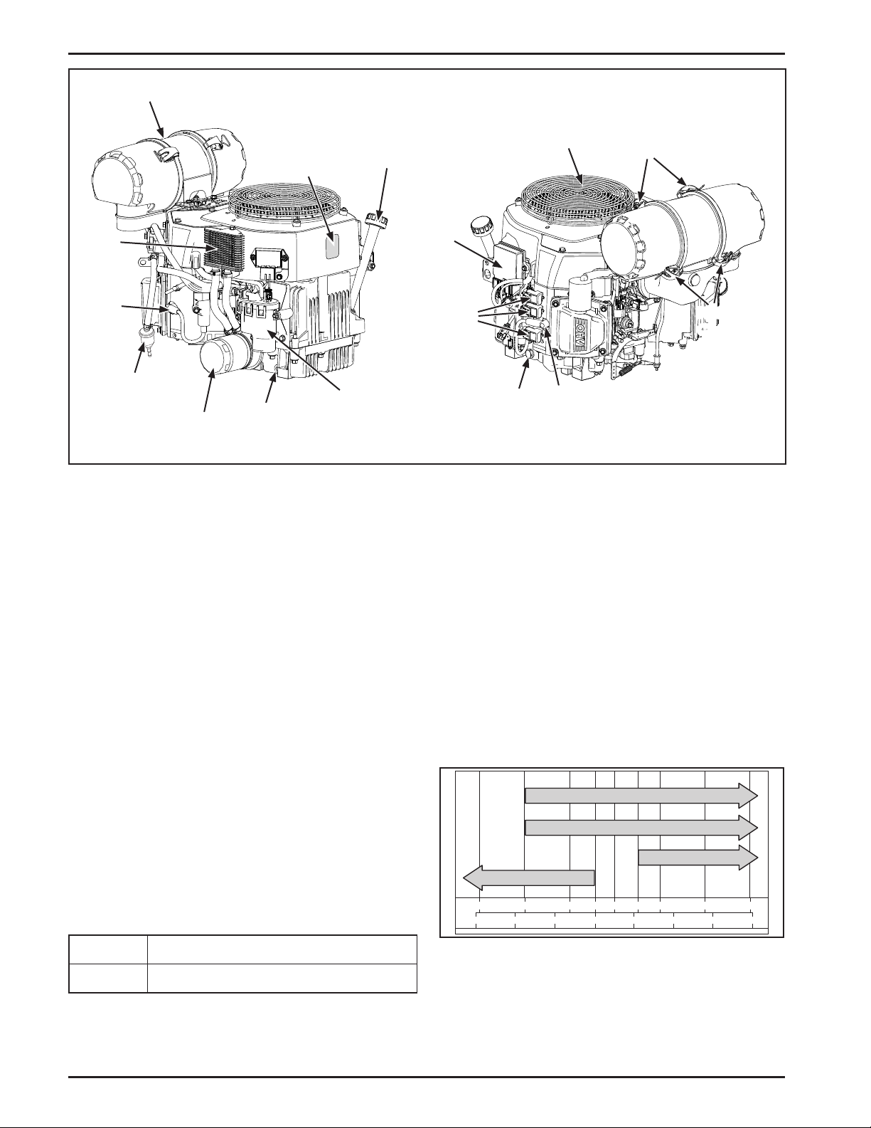
Air Cleaner
Serial and
Data Label
Oil Fill Cap/
Dipstick
Oil
Cooler
Spark
Plug
Fuel Filter
(Special EFI)
Oil
Filter
Oil Drain
Plug
Fuel
Pump
Module
Figure 1. Control and Service Point Locations.
Electronic
Control
Unit
(ECU)
Fuses
(Early
Location)
Oil
Drain
Plug
Fixed
Guard
Spark
Plug
Retaining
Clips
Retaining
Clips
Engine Identication Numbers
When ordering parts, or in any communication
involving an engine, always give the Model,
Specication, and Serial Numbers of the engine.
The engine identication numbers appear on a decal
(or decals) axed to the engine shrouding. Include
leer suxes, if there are any.
Emission Compliance Period
The Emission Compliance Period referred to on the
Emission Control or Air Index label indicates the
number of operating hours for which the engine has
been shown to meet Federal and CARB emission
requirements. The following table provides the
Engine Compliance Period (in hours) associated with
the category descriptor which may be found on the
certication label.
Refer to certication label for engine displacement.
Exhaust Emission Control System for models ECV630,
ECV650, ECV680, ECV730, ECV740, ECV749 is EM,
O2S, ECM, MPI for U.S. EPA, California, and Europe.
Oil Recommendations
Using the proper type and weight of oil in the
crankcase is extremely important. So is checking oil
daily and changing oil regularly. Failure to use the
correct oil, or using dirty oil, causes premature engine
wear and failure.
Oil Type
Use high quality detergent oil of API (American
Petroleum Institute) service class SJ or higher. Select
the viscosity based on the air temperature at the
time of operation as shown in the Recommended
Viscosity Grades table.
Kohler 10W-30
10W-30
SAE 30
5W-30
°F -20 0 20 32 40 60
°C -30 -20 -10 0 10 20 30 40
50 80 100
EPA Category A:1000 hours
CARB Extended:500 hours
4
Figure 2. Recommended Viscosity Grades Table.
Refer to Maintenance Instructions for detailed oil
check, oil change, and oil lter change procedures.
Page 5
Fuel Recommendations
Pre-Start Checklist
1. Check oil level. Add oil if low. Do not overll.
WARNING
Explosive Fuel can cause res
and severe burns.
Do not ll the fuel tank while the
engine is hot or running.
Gasoline is extremely ammable and its vapors can explode
if ignited. Store gasoline only in approved containers, in
well ventilated, unoccupied buildings, away from sparks or
ames. Do not ll the fuel tank while the engine is hot or
running, since spilled fuel could ignite if it comes in contact
with hot parts or sparks from ignition. Do not start the
engine near spilled fuel. Never use gasoline as a cleaning
agent.
General Recommendations
Purchase gasoline in small quantities and store
in clean, approved containers. A container with a
capacity of 2 gallons or less with a pouring spout is
recommended. Such a container is easier to handle
and helps eliminate spillage during refueling.
Do not use gasoline le over from the previous season,
to minimize gum deposits in your fuel system and to
ensure easy starting.
Do not add oil to the gasoline.
Do not overll the fuel tank. Leave room for the fuel to
expand.
Fuel Type
For best results use only clean, fresh, unleaded
gasoline with a pump sticker octane rating of 87
(R+M)/2 or higher. In countries using the Research
Octane Number (RON), it should be 90 octane
minimum. Leaded gasoline is not recommended and
must not be used on EFI engines or on other models
where exhaust emissions are regulated.
NOTE: Engines are shipped without oil. Do not start
engine with no or low oil. This will cause
damage to the engine and will not be covered
under warranty.
2. Check fuel level. Add fuel if low.
3. Check cooling air intake areas and external
surfaces of engine. Make sure they are clean and
unobstructed.
4. Check that the air cleaner components and all
shrouds, equipment covers, and guards are in
place and securely fastened.
5. Check that any clutches or transmissions are
disengaged or placed in neutral. This is especially
important on equipment with hydrostatic drive.
The shi lever must be exactly in neutral to
prevent resistance which could keep the engine
from starting.
WARNING
Carbon Monoxide can cause
severe nausea, fainting or death.
Avoid inhaling exhaust fumes, and
never run the engine in a closed
building or conned area.
Engine exhaust gases contain poisonous carbon monoxide.
Carbon monoxide is odorless, colorless, and can cause death
if inhaled. Avoid inhaling exhaust fumes, and never run the
engine in a closed building or conned area.
Starting
1. Place the throle control midway between the
SLOW and FAST positions.
2. Start the engine by activating the key switch.
Release the switch as soon as the engine starts.
Gasoline/Alcohol blends
Gasohol (up to 10% ethyl alcohol, 90% unleaded
gasoline by volume) is approved as a fuel for Kohler
engines. Other gasoline/alcohol blends including E20
and E85 are not to be used and not approved. Any
failures resulting from use of these fuels will not be
warranted.
Gasoline/Ether blends
Methyl Tertiary Butyl Ether (MTBE) and unleaded
gasoline blends (up to a maximum of 15% MTBE by
volume) are approved as a fuel for Kohler engines.
Other gasoline/ether blends are not approved.
Operating Instructions
Also read the operating instructions of the equipment this
engine powers.
a. Turn the key switch to the ON position for
one minute. Allow the fuel pump to cycle
and prime the system. Turn the key switch
OFF.
b. Turn the key switch to the START position,
crank and start engine.
c. If the engine fails to start, repeat steps a
and b. If the engine does not start aer
two priming intervals, contact your Kohler
Engine Service Center for further assistance.
NOTE: Do not crank the engine continuously for
more than 10 seconds at a time. If the engine
does not start, allow a 60 second cool down
period between starting aempts. Failure
to follow these guidelines can damage the
starter motor.
5
Page 6
NOTE: Upon start-up, a metallic ticking may occur.
This is caused by hydraulic lier leakdown
during storage. The noise will normally cease
in the rst minute. If noise continues, run
the engine at mid-throle for 20 minutes. If
noise persists, take the engine to your Kohler
Engine Service Center.
NOTE: If the starter cranks the engine but does not
start the engine, the engine rotation must be
allowed to come to a complete stop before
aempting to restart the engine. If the starter
is engaged while the ywheel is rotating, the
starter pinion and ywheel ring gear may
clash, resulting in damage to the starter.
this engine powers. Because of equipment design or
application, there may be more stringent restrictions
regarding the angle of operation.
NOTE: Do not operate this engine continuously
at angles exceeding 25° in any direction.
Engine damage could result from insucient
lubrication.
WARNING
Hot Parts can cause severe burns.
Do not touch engine while operating or
just aer stopping.
If the starter does not turn the engine over, shut o
starter immediately. Do not make further aempts to
start the engine until the condition is corrected. Do
not jump start using another baery (refer to Baery).
See your Kohler Engine Service Center for service
assistance.
Stopping
1. Remove the load by disengaging all PTO driven
aachments.
2. Move the throle to the slow or idle position; turn
key OFF to stop engine.
Battery
A 12 volt baery is used. Refer to the operating
instructions of the equipment this engine powers for
specic baery requirements.
If the baery charge is not sucient to crank the
engine, recharge the baery. Follow the baery
manufacturer's instructions.
Operating
Cooling
NOTE: If debris builds up on the xed guard or other
cooling areas, stop the engine immediately
and clean. Operating the engine with blocked
or dirty air intake and cooling areas can cause
extensive damage due to overheating. Refer to
Clean Air Intake/Cooling Areas.
Engine Speed
NOTE: Do not tamper with the governor seing to
increase the maximum engine speed.
Overspeed is hazardous and will void the
engine warranty. The maximum allowable
high idle speed for these engines is 4200 RPM,
no load.
Maintenance Instructions
Normal maintenance, replacement or repair of emission
control devices and systems may be performed by any
repair establishment or individual; however, warranty
repairs must be performed by a Kohler authorized
service center.
Angle of Operation
This engine will operate continuously at angles up to
25°. Check oil level to assure crankcase oil level is at
the F mark on the dipstick.
Refer to the operating instructions of the equipment
6
Page 7

WARNING
Accidental Starts can cause severe injury or death.
Disconnect and ground spark plug leads before servicing.
Disabling engine. Accidental starting can cause severe injury or death. Before working on the engine or equipment, disable the
engine as follows: 1) Disconnect the spark plug lead(s). 2) Disconnect negative (-) baery cable from baery.
Maintenance Schedule
These required maintenance procedures should be performed at the frequency stated in the table below. They
should also be included as part of any seasonal tune-up.
Frequency Maintenance Required
• Check oil level.
Daily or Before
Starting Engine
Every 25 Hours
Every 100 Hours
Weekly or Every 150
Hours
Every 200 Hours
Annually or
Every 300 Hours
Annually or
Every 500 Hours
¹Perform these maintenance procedures more frequently under extremely dusty, dirty conditions.
²Have a Kohler Engine Service Dealer perform this service.
3
Low-prole air cleaner.
4
Heavy-duty air cleaner.
• Fill fuel tank.
• Check air cleaner for dirty
• Check air intake and cooling areas, clean as necessary.
• Clean or replace precleaner (if equipped) clean as necessary.
1
• Replace element
(low-prole air cleaner models).
• Remove and clean shrouds and cooling areas.
1
, loose, or damaged parts.
1
1
1,3
• Change oil. (More frequently under severe conditions).
• Check oil cooler ns, clean as necessary (if equipped).
• Check lter minder.
• Inspect air lter paper element and inlet screen area.
• Replace fuel lter.
4
4
1
• Clean, set gap or replace spark plug, and set gap.
• Change oil lter.
• Replace heavy-duty air cleaner element and check inner element.
• Have starter serviced.
2
1
Check Oil Level
The importance of checking and maintaining
the proper oil level in the crankcase cannot be
overemphasized. Check oil BEFORE EACH USE as
follows:
1. Make sure the engine is stopped, level, and is cool
so the oil has had time to drain into the sump.
2. Clean the area around and beneath the oil ll cap/
dipstick before removing it. This will help keep
dirt, debris, and other foreign maer out of the
engine. See Figure 3.
Oil Fill Cap/
Dipstick
Oil Fill
Tube
Figure 3. Oil Fill Cap/Dipstick and Oil Fill Tube.
7
Page 8

3. Unscrew and remove the oil ll cap/dipstick;
wipe o oil. Reinsert the dipstick into the oil ll
tube and rest the cap on the tube. Do not thread
the cap onto the tube.
Change Oil
Change oil aer every 100 hours of operation (more
frequently under severe conditions). Rell with oil as
specied in the Viscosity Grades Table. See Figure 2.
4. Remove the oil ll cap/dipstick and check oil level
is correct. The correct oil level is between the F
and L marks on the dipstick. See Figure 4.
Oil Fill
Cap
Dipstick
Figure 4. Correct Oil Level.
5. If the level is low, add oil of the proper type (Refer
to Oil Type) and to the correct level. Always check
the level before adding more oil.
NOTE: To prevent extensive engine wear or
damage, always maintain the oil level
within the Operating Range.
Operating
Range
Change the oil while the engine is still warm. The oil
will ow more freely and carry away more impurities.
Make sure the engine is level when lling, checking, or
changing the oil.
Change the oil as follows:
1. To keep dirt, debris, etc., out of the engine, clean
the area around the oil ll cap/dipstick before
removing it. See Figure 3.
2. Remove one of the oil drain plugs and the oil
ll cap/dipstick. Allow ample time for complete
drainage. See Figures 5 and 6.
Oil Drain Plug
Figure 5. Oil Drain Plug (Starter Side).
3. Reinstall the drain plug and torque to
13.6 N·m (10 . lb.).
4. Fill the crankcase, with new oil of the proper type,
to the F mark on the dipstick. Refer to Oil Type.
Always check the level with the dipstick before
adding more oil.
6. Reinstall the oil ll cap/dipstick and tighten on oil
ll tube.
Oil Sentry™
Some engines are equipped with an optional Oil
Sentry™ switch. This switch is designed to prevent the
engine from starting in a low oil or no oil condition.
The Oil Sentry™ may not shut down a running
engine before damage occurs. In some applications
this switch may activate a warning signal. Read your
equipment manuals for more information.
NOTE: Make sure the oil level is checked BEFORE
EACH USE and is maintained up to the F
mark on the dipstick. This includes engines
equipped with Oil Sentry™.
Oil Disposal
Protect and respect the environment. Dispose of oil
at your local recycling center or municipal collection
center in accordance with local ordinances.
8
5. Reinstall the oil ll cap/dipstick and tighten
securely.
NOTE: To prevent extensive engine wear or
damage, always maintain the proper oil
level in the crankcase. Never operate
the engine with the oil level below the
L mark or above the F mark on the
dipstick.
Change Oil Filter
Replace the oil lter at least every other oil change
(every 200 hours of operation). Always use a genuine
Kohler oil lter. Replace the oil lter as follows:
1. Drain the oil from the engine crankcase. Remove
one of the oil drain plugs and the oil ll cap/
dipstick. Allow ample time for complete drainage.
See Figures 3, 5, and 6.
2. Allow the oil lter to drain.
Page 9

3. Before removing the oil lter, clean the area
around the oil lter to keep dirt and debris out
of the engine. Remove the old lter. Wipe o the
surface where the lter mounts. See Figure 6.
Oil Filter
Figure 6. Oil Filter and Oil Drain Plug.
4. Place a new replacement lter in a shallow pan
with the open end up. Pour new oil, of the proper
type, in through the threaded center hole. Stop
pouring when the oil reaches the boom of the
threads. Allow a minute or two for the oil to be
absorbed by the lter material.
Oil Drain Plug
Mounting
Hardware
Figure 7. Oil Cooler (Blower Housing Mount).
Oil Cooler
Air Cleaner
General
These engines use a heavy-duty style air cleaner
shown in Figure 8, consisting of a cylindrical housing
mounted to the carburetor and intake manifold. The
air cleaner housing contains a paper element and inner
element, designed for longer service intervals. The
system is CARB/EPA certied and the components
should not be altered or modied in any way.
5. Apply a thin lm of clean oil to the rubber gasket
on the new lter.
6. Install the new oil lter to the lter adapter or oil
cooler. Refer to instructions on the oil lter for
proper installation.
7. Reinstall the drain plug. Make sure it is tightened
to 13.6 N·m (10 . lb.) torque.
8. Fill the crankcase with new oil, of the proper type,
to the F mark on the dipstick.
9. Test run the engine to check for leaks. Stop the
engine, allow a minute for the oil to drain down,
and recheck the level on the dipstick. Make sure
oil level is up to but not over the F mark on the
dipstick.
Service Oil Cooler
Some engines are equipped with an optional oil
cooler. Inspect and clean oil cooler every 100 hours of
operation (more frequently under severe conditions).
Oil cooler must be kept free of debris. To service the
oil cooler, clean the outside of ns with a brush. See
Figure 7. Remove the hardware holding the cooler unit
to the blower housing. Clean the inside of the cooler
with a brush. Aer cleaning, reinstall the oil cooler to
the blower housing with the mounting hardware.
Filter
Minder
Figure 8. Heavy-Duty Style Air Cleaner.
Service
Weekly and every 150 hours: Check lter minder (if
equipped), Perform inspection of the paper element
and inlet screen area.
Annually or every 300 hours of operation (more oen
under extremely dusty or dirty conditions), replace
the paper element and check the inner element. Follow
these steps.
1. Unhook the two retaining clips on each end and
remove the end caps from the air cleaner housing.
See Figure 1.
9
Page 10

2. Check and clean the inlet screen. Pull the air
cleaner paper element out of the housing on
opposite side. See Figures 9 and 10.
Ejector
Area
Inlet Screen
Figure 9. Accessing Inlet Screen.
Paper Element
Inner Element
Figure 10. Removing Elements.
3. Aer the paper element is removed, check the
condition of the inner element. It should be
replaced whenever it appears dirty, typically
every other time the main element is replaced or
every 600 hours. Clean the area around the base
of the inner element before removing it, so dirt
does not get into the engine.
4. Do not wash the paper element and inner
element or use compressed air, this will damage
the elements. Replace dirty, bent or damaged
elements with new genuine Kohler elements as
required. Handle the new elements carefully;
do not use if the sealing surfaces are bent or
damaged.
5. Check all parts for wear, cracks, or damage, and
make sure ejector area is clean. See Figure 11.
Replace any damaged components.
Figure 11. Ejector Area.
6. Install the new inner element, followed by the
paper element. Slide each fully into place in the
air cleaner housing.
7. Reinstall the end caps and secure with the
retaining clips. See Figure 1.
Clean Air Intake/Cooling Areas
To ensure proper cooling, make sure the xed guard,
cooling ns, and other external surfaces of the engine
are kept clean at all times.
Every 100 hours of operation (more oen under
extremely dusty, dirty conditions), remove the blower
housing and other cooling shrouds. Clean the cooling
ns and external surfaces as necessary. Reinstall the
blower housing and other cooling shrouds.
NOTE: Operating the engine with a blocked xed
guard, dirty or plugged cooling ns, and/or
cooling shrouds removed, will cause engine
damage due to overheating.
Ignition System
EFI Engines incorporate a computer-controlled baery
ignition system with individual coils. Other than
periodically checking/replacing the spark plugs, no
maintenance, timing, or adjustments are necessary or
possible with this system.
Check Spark Plugs
Every 200 hours of operation, remove the spark plugs,
check condition, and reset the gap or replace with
new plugs as necessary. The standard spark plug is a
Champion® RC12YC (Kohler Part No. 12 132 02-S). RFI
compliant engines use a Champion® XC12YC (Kohler
Part No. 25 132 14-S) spark plug. A high-performance
spark plug, Champion® Platinum 3071 (used on Pro
Series engines, Kohler Part No. 25 132 12-S) is also
available. Equivalent alternate brand plugs can also be
used.
10
Page 11

1. Before removing the spark plug, clean the area
around the base of the plug to keep dirt and
debris out of the engine.
2. Remove the plug and check its condition. Replace
the plug if worn or reuse is questionable.
NOTE: Do not clean the spark plug in a machine
using abrasive grit. Some grit could
remain in the spark plug and enter the
engine causing extensive wear and
damage.
3. Check the gap using a wire feeler gauge. Adjust
the gap to 0.76 mm (0.030 in.) by carefully
bending the ground electrode. See Figure 12.
Wire Gauge
Spark Plug
Fuel System
WARNING
High Pressure Fluids can puncture
skin and cause severe injury or death.
Do not work on fuel system without
proper training and safety equipment.
General
The precision components inside the fuel pump
module are not serviceable. DO NOT aempt to open
the fuel pump module. Damage to the components
will result and the warranty will be void. Because
the fuel pump module is not serviceable, the engines
are equipped with a special 10-micron EFI fuel lter
to prevent harmful contamination from entering the
module. See Figure 1.
If there are two lters in the system, the one before
the li pump will be a standard 51-75 micron lter,
and the one aer the li pump will be the special
10-micron lter. Be sure to use an approved 10-micron
lter for replacement.
Ground
Electrode
Figure 12. Servicing Spark Plug.
4. Reinstall the spark plug into the cylinder
head. Torque the spark plug to 24.4-29.8 N·m
(18-22 . lb.).
0.76 mm
(0.030 in.) Gap
Battery Charging
Follow all the baery warnings and safety guidelines
and procedures provided by the baery manufacturer
and equipment manufacturer.
Jump Starting
Follow all safety guidelines and procedures provided
by the baery manufacturer and/or original
equipment manufacturer (OEM). Failure to follow
proper procedures may result in serious personal
injury and/or non-warrantable damage to the engine's
Electronic Fuel Injection (EFI) components.
Service
Periodically inspect the lter and replace every 200
operating hours or more frequently under extremely
dusty or dirty conditions. Use only a genuine Kohler
lter (Kohler Part No. 25 050 42-S) and install it
according to the directional arrows. Failure to use the
proper lter can result in engine damage and void the
warranty.
Fuel Line
These engines use low permeation rated fuel lines,
certied to comply with California and U.S. EPA
evaporative emission requirements. Fuel lines that do
not meet these requirements may not be used. Order
replacement hose through a Kohler Service Center.
A high pressure fuel line runs between the high
pressure pump and the injectors. This special fuel line,
capable of withstanding the high pressure of the EFI
fuel system and meets SAE R9 specications. If fuel
line must be replaced, see your Kohler Engine Service
Center.
11
Page 12

Electronic Fuel Injection (EFI) System
The EFI system is a complete, electronicallycontrolled, fuel management system, designed to
deliver a precisely controlled fuel ow under all
operating conditions. The electronic control unit
(ECU), the brain of the system, automatically adjusts
fuel delivery and ignition timing based upon load,
speed, operating temperature, and exhaust emission
levels. The low idle speed is the only manual
adjustment possible. The ECU continuously monitors
operation of the EFI system. If it detects a problem
or fault within the system, it will illuminate the
Malfunction Indicator Light (MIL) (if so equipped).
This is a signal that normal, programmed operation
has been aected, and service by an authorized Kohler
Engine Service Center is required. In most cases a MIL
light may be added to an engine, see Parts Ordering.
*NOTE: The actual low idle speed depends on
the application -- refer to equipment
manufacturer's recommendations.
When an EFI engine is started cold, the ECU will
briey set a higher (200-400 RPM) low idle speed,
similar to a fast idle. Do not aempt to perform any
readjustment during this warm-up period.
If adjustment is to be made, the engine must be at
operating temperature, air cleaner in place, and check
engine light must be o (no fault codes present).
1. Start the engine and run at half throle for 5 to 10
minutes to warm up.
2. Place the throle control into the idle or slow
position.
Troubleshooting
If the MIL comes on, or the engine becomes hard to
start, runs roughly, or stalls at low idle speed, initial
checks should be made in the following areas:
• Check that the fuel tank is lled with clean, fresh
gasoline, and shut-o valve (if so equipped) is
opened completely.
• Check that the fuel tank vent cap is not blocked
and it is operating properly (non-California
models).
• Check that the air cleaner element and precleaner
are clean and all components are properly
secured. Clean or replace as necessary.
• Check that the proper fuel lter is being used,
and it is clean and unobstructed. Replace lter(s)
only with genuine Kohler parts.
• Check that all connections to sensors, ECU, and
fuel injectors are properly secured.
• Check that a good 12 volt baery is being used
and is fully charged.
• Check that fuses are not burned out. If so then
replace.
If these checks do not correct the problem, or the MIL
remains on, further diagnosis and servicing by an
authorized Kohler Engine Service Center is necessary.
Adjustment – Throttle Body
Low Idle Speed (RPM) is the only adjustment that can
be made. All other fuel calibrations are controlled by
the ECU. The standard low idle speed is 1500 RPM*
(± 75 RPM).
3. Turn the low idle speed adjusting screw in or out
and check RPM with a tachometer. See Figure 13.
Adjusting
Screw
Figure 13. Throttle Body Manifold.
Fuse Replacement
This engine has 3 blade type automotive fuses.
Replacement fuses must have the same rating as
the blown fuse. Use the fuse rating chart below to
determine the correct fuse. See Figure 14.
Wire Color Fuse Rating
2 Solid Red Wires 10-amp Fuse
1 Red Wire with Black Stripe
1 Red Wire with White Stripe
2 Purple Wires 30-amp Fuse
Figure 14. Fuse Rating Chart.
To replace a fuse:
1. Shut engine o and remove key.
2. Locate the fuse holders.
10-amp Fuse
12
3. Remove the fuse cover and pull out fuse. See
Figure 15.
Page 13
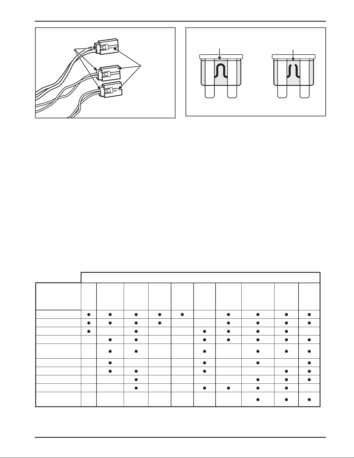
Fuse
Holder
Cover
Solid
Fusible Link
Broken
Fusible Link
Figure 15. Fuse Holders and Covers.
4. Inspect the fuse for a broken fusible link. See
Figure 16. Replace the fuse if the fusible link is
Good Fuse
Figure 16. Good and No Good Blade Type Fuses.
5. Install the fuse into the fuse holder until it is
seated properly. Install the fuse cover.
No Good Fuse
broken. If you are not sure if the link is broken,
replace the fuse.
Additional Electrical Information
The yellow accessory wire from on the original Kohler Engine key switch can not draw more than 2-amps. A
relay may be used in order to use a higher drawing accessory. Contact a Kohler Engines application specialist for
further instructions. A current draw of more than 2-amps will cause damage to the ECU, Fuel Pump Module, or
other electrical system components and will void the warranty.
Troubleshooting
When troubles occur, be sure to check the simple causes which, at rst, may seem too obvious to be considered.
For example, a starting problem could be caused by an empty fuel tank. Some common causes of engine troubles
are listed in the following table.
Do not aempt to service or replace major engine components, or any items that require special timing or
adjustment procedures. Have your Kohler Engine Service Center do this work.
Problem
Will Not Start
Hard Starting
Stops Suddenly
Lacks Power
Operates
Erratically
Knocks or Pings
Skips or Misres
Backres
Overheats
High Fuel
Consumption
No
Fuel
Improper
Fuel
Blocked
Fuel
Line/
System
Low
Battery
Voltage
Possible Cause
Broken
Fusible
Link
Dirty
Fixed
Guard
Incorrect
Oil Level
Engine
Overloaded
Dirty Air
Cleaner
Faulty
Spark
Plug
13
Page 14

Storage
If the engine will be out of service for two months or
more, use the following storage procedure:
1. Clean the exterior surfaces of the engine. On
EFI engines, avoid spraying water at the wiring
harness or any of the electrical components.
Parts Ordering
The engine Specication, Model, and Serial Numbers
are required when ordering replacement parts from
your Kohler Engine Service Center. These numbers are
found on the identication plate which is axed to the
engine shrouding. Include leer suxes if there are
any. Refer to Serial and Data Label.
2. Change the oil and lter while the engine is still
warm from operation. Refer to Change Oil and
Filter.
3. The fuel system must be completely emptied,
or the gasoline must be treated with a stabilizer
to prevent deterioration. If you choose to
use a stabilizer, follow the manufacturers
recommendations, and add the correct amount
for the capacity of the fuel system. Fill the fuel
tank with clean, fresh gasoline. Run the engine
for 2-3 minutes to get stabilized fuel into the fuel
system. Close fuel shut o valve when unit is
being stored or transported.
To empty the system, run the engine until the
tank and fuel system are empty.
4. Remove the spark plugs. Add one tablespoon of
engine oil into each spark plug hole. Install plugs,
but do not connect the plug leads. Crank the
engine two or three revolutions.
5. Disconnect the negative (-) baery cable or use a
Baery Minder trickle charger while the unit is in
storage.
Always insist on genuine Kohler parts. All genuine
Kohler parts meet strict standards for t, reliability,
and performance.
Major Repair
Major repair information is available in Kohler Engine
Service Manuals. This type of repair generally requires
the services of a trained mechanic and the use of
special tools and equipment. Kohler Engine Service
Centers have the facilities, training, and genuine
Kohler replacement parts necessary to perform this
service.
For the nearest sales and service location:
• Visit our Web site: www.KohlerEngines.com
• Call 1-800-544-2444 (U.S. and Canada)
• Look in your local telephone directory under
Engines-Gasoline
6. Store the engine in a clean, dry place.
14
Page 15

Specications
Model: ECV630 ECV650 ECV680 ECV730 ECV740 ECV749
Bore:
Stroke:
Displacement:
(in.3)
*Gross Power
(@ 3600 RPM):
(HP)
*Net Power
(@ 3600 RPM):
Peak Torque (Minimum):
(HP)
N·m
(ft. lb.)
Compression Ratio:
Weight:
Oil Capacity:
(lbs.)
(U.S. qt.)
Exhaust Emission Control System:
mm
(in.)
mm
(in.)
cm
kW
kW
kg
3
L
694
(42.4)
14.1
(19)*
13.8**
(18.6)**
42.8**
(31.6)**
EM, O2S, ECM, MPI for U.S. EPA, California, and Europe
80
(3.2)
69
(2.72)
694
(42.4)
15.7
(21)*
14.6**
(19.6)**
44.3**
(32.7)
8.8:1 9.1:1
46**
(102)**
1.9
(2)
694
(42.4)
17.2
(23)*
15.4**
(20.7)**
46.8**
(34.5)**
747
(45.6)
18.6
(25)*
16.6
(22.2)
49.4
(36.4)
(102)**
83
(3.3)
69
(2.72)
747
(45.6)
20.1
(27)*
17.4
(23.3)
50.7
(37.4)
46**
1.9
(2)
747
(45.6)
21.6
(29)*
17.7
(23.8)
51.8
(38.2)
*Horsepower ratings exceed Society of Automotive Engineers Small Engine Test Code J1940. Actual engine
horsepower is lower and aected by, but not limited to, accessories (air cleaner, exhaust, charging, cooling,
fuel pump, etc.), application, engine speed and ambient operating conditions (temperature, humidity, and
altitude). Kohler reserves the right to change product specications, designs, and equipment without notice
and without incurring obligation
**Based on preliminary information.
15
Page 16

LIMITED 3 YEAR COMMAND ENGINE WARRANTY
Kohler Co. warrants to the original consumer that each new COMMAND engine sold by Kohler Co. will be free from manufacturing
defects in materials or workmanship in normal service for a period of three (3) years from date of purchase, provided it is operated and
maintained in accordance with Kohler Co.’s instructions and manuals.
Our obligation under this warranty is expressly limited, at our option, to the replacement or repair at Kohler Co., Kohler, Wisconsin 53044,
or at a service facility designated by us of such parts as inspection shall disclose to have been defective.
EXCLUSIONS:
Muers on engines used commercially (non-residential) are warranted for one (1) year from date of purchase, except catalytic muers,
which are warranted for three (3) years.
This warranty does not apply to defects caused by casualty or unreasonable use, including faulty repairs by others and failure to provide
reasonable and necessary maintenance.
The following items are not covered by this warranty:
Engine accessories such as fuel tanks, clutches, transmissions, power-drive assemblies, and baeries, unless supplied or installed by Kohler
Co. These are subject to the warranties, if any, of their manufacturers.
KOHLER CO. AND/OR THE SELLER SHALL NOT BE LIABLE FOR SPECIAL, INDIRECT, INCIDENTAL, OR CONSEQUENTIAL
DAMAGES OF ANY KIND, including but not limited to labor costs or transportation charges in connection with the repair or replacement
of defective parts.
IMPLIED OR STATUTORY WARRANTIES, INCLUDING WARRANTIES OF MERCHANTABILITY OR FITNESS FOR A PARTICULAR
PURPOSE, ARE EXPRESSLY LIMITED TO THE DURATION OF THIS WRITTEN WARRANTY. We make no other express warranty, nor is
any one authorized to make any on our behalf.
Some states do not allow limitations on how long an implied warranty lasts, or the exclusion or limitation of incidental or consequential
damages, so the above limitation or exclusion may not apply to you.
This warranty gives you specic legal rights, and you may also have other rights which vary from state to state.
TO OBTAIN WARRANTY SERVICE:
Purchaser must bring the engine to an authorized Kohler service facility. To locate the nearest facility, visit our website
www.KohlerEngines.com, or telephone 1-800-544-2444, consult your local telephone directory.
ENGINE DIVISION, KOHLER CO., KOHLER, WISCONSIN 53044
16
Page 17

KOHLER CO.
FEDERAL AND CALIFORNIA EMISSION CONTROL SYSTEMS
LIMITED WARRANTY
SMALL OFF-ROAD AND CLASS 1 LSI ENGINES
The U.S. Environmental Protection Agency (EPA), the California Air Resources Board (CARB), and Kohler Co. are pleased to explain the
2011 and later Federal and California Emission Control Systems Warranty on your o-road equipment engine. “Emissions“ means both
exhaust and evaporative emissions. For California, small o-road engines, and Class 1 LSI (Large Spark Ignited engines at or below 1.0
liter) must be designed, built and equipped to meet the state’s stringent anti-smog standards. In other states, engines must be designed,
built and equipped, to meet the U.S. EPA regulations for small non-road engines. The engine must be free from defects in materials and
workmanship which cause it to fail to conform with U.S. EPA standards for the rst three years of engine use from the date of sale to the
ultimate purchaser. Kohler Co. must warrant the emission control system on the engine for the period of time listed above, provided there
has been no abuse, neglect or improper maintenance.
The emission control system may include parts such as the carburetor or fuel injection system, the ignition system, and catalytic converter.
Also included are the hoses, belts and connectors and other emission related assemblies.
Where a warrantable condition exists, Kohler Co. will repair the engine at no cost, including diagnosis (if the diagnostic work is performed
at an authorized dealer), parts and labor.
MANUFACTURER’S WARRANTY COVERAGE
Small o-road engines and Class 1 LSI engines are warranted for three years in California and other states. If any emission related part on
the engine is defective, the part will be repaired or replaced by Kohler Co. free of charge.
OWNER’S WARRANTY RESPONSIBILITIES
(a) The engine owner is responsible for the performance of the required maintenance listed in the owner’s manual. Kohler Co.
recommends that you retain all receipts covering maintenance on the engine, but Kohler Co. cannot deny warranty solely for the
lack of receipts or for your failure to assure that all scheduled maintenance was performed.
(b) Be aware, however, that Kohler Co. may deny warranty coverage if the engine or a part has failed due to abuse, neglect, improper
maintenance or unapproved modications.
(c) For warranty repairs, the engine must be presented to a Kohler Co. service center as soon as a problem exists. Call 1-800-544-2444
or access our web site at: www.kohlerengines.com, for the names of the nearest service centers. The warranty repairs should be
completed in a reasonable amount of time, not to exceed 30 days.
If you have any questions regarding warranty rights and responsibilities, you should contact Kohler Co. at 1-920-457-4441 and ask for an
Engine Service representative.
COVERAGE
Kohler Co. warrants to the ultimate purchaser and each subsequent purchaser that the engine will be designed, built and equipped, at
the time of sale, to meet all applicable regulations. Kohler Co. also warrants to the initial purchaser and each subsequent purchaser, that
the engine is free from defects in materials and workmanship which cause the engine to fail to conform with applicable regulations for a
period of three years.
Small o-road engines and Class 1 LSI engines are warranted for three years in California. EPA requires manufacturers to warrant engines
for three years in all other states. These warranty periods will begin on the date the engine is purchased by the initial purchaser. If any
emission related part on the engine is defective, the part will be replaced by Kohler Co. at no cost to the owner. Kohler Co. is liable for
damages to other engine components caused by the failure of a warranted part still under warranty.
Kohler Co. shall remedy warranty defects at any authorized Kohler Co. engine dealer or warranty station. Warranty repair work done at
an authorized dealer or warranty station shall be free of charge to the owner if such work determines that a warranted part is defective.
Continued on next page.
17
Page 18

Listed below are the parts covered by the Federal and California Emission Control Systems Warranty. Some parts listed below may require
scheduled maintenance and are warranted up to the rst scheduled replacement point for that part. The warranted parts include the
following if they were present in the engine purchased:
• Oxygen sensor (if equipped) • Ignition module(s) with high tension lead
• Intake manifold (if equipped) • Gaseous fuel regulator (if equipped)
• Exhaust manifold (if equipped) • Electronic control unit (if equipped)
• Catalytic muer (if equipped) • Carburetor or fuel injection system
• Thermal reactor muer (if equipped) • Fuel metering valve (if equipped)
• Fuel lines, fuel line ings and clamps (if equipped) • Air lter, fuel lter, and spark plugs (only
• Spark advance module (if equipped) to rst scheduled replacement point)
• Crankcase breather • Evaporative System (if equipped)
• Air Injection System (if equipped) - Canister (if equipped)
- Air pump or pulse valve assembly (if equipped) - Canister lter (if equipped)
- Control/distribution valve (if equipped) - Vapor hose (if equipped)
- Distribution manifold (if equipped) - Orice connector (if equipped)
- Air hoses (if equipped) - Fuel tank (if equipped)
- Vacuum lines (if equipped) - Fuel cap (if equipped)
- Primer bulb canister (if equipped)
LIMITATIONS
This Emission Control Systems Warranty shall not cover any of the following:
(a) repair or replacement required because of misuse or neglect, improper maintenance, repairs improperly performed or
replacements not conforming to Kohler Co. specications that adversely aect performance and/or durability and alterations or
modications not recommended or approved in writing by Kohler Co.,
(b) replacement of parts and other services and adjustments necessary for required maintenance at and aer the rst scheduled
replacement point,
(c) consequential damages such as loss of time, inconvenience, loss of use of the engine or equipment, etc.,
(d) diagnosis and inspection fees that do not result in eligible warranty service being performed, and
(e) any add-on or modied part, or malfunction of authorized parts due to the use of add-on or modied parts.
MAINTENANCE AND REPAIR REQUIREMENTS
The owner is responsible for the proper use and maintenance of the engine. Kohler Co. recommends that all receipts and records
covering the performance of regular maintenance be retained in case questions arise. If the engine is resold during the warranty period,
the maintenance records should be transferred to each subsequent owner. Kohler Co. reserves the right to deny warranty coverage if
the engine has not been properly maintained; however, Kohler Co. may not deny warranty repairs solely because of the lack of repair
maintenance or failure to keep maintenance records.
Normal maintenance, replacement or repair of emission control devices and systems may be performed by any repair establishment or
individual; however, warranty repairs must be performed by a Kohler authorized service center. Any replacement part or service that
is equivalent in performance and durability may be used in non-warranty maintenance or repairs, and shall not reduce the warranty
obligations of the engine manufacturer.
18
Page 19

19
Page 20

FOR SALES AND SERVICE INFORMATION
IN U.S. AND CANADA, CALL 1-800-544-2444
KohlerEngines.com
ENGINE DIVISION, KOHLER CO., KOHLER, WISCONSIN 53044
© 2010 by Kohler Co. All rights reserved.
FORM NO.: 24 590 17 Rev. A
ISSUED: 10/10
REVISED: 11/10
 Loading...