

Page 1

Operation
Industrial Generator Sets
Models:
20-3250 kW
Controllers:
Decision-Makerr 550
Software (Code) Version 2.10 or higher
TP-6200 10/12i
Page 2

California Proposition 65
WARNING
Engine exhaust from this product contains chemicals
known to the State of California to cause cancer, birth
defects, or other reproductive harm.
Product Identification Information
Product identification numbers determine service parts.
Record the product identification numbers in the spaces
below immediately after unpacking the products so that
the numbers are readily available for future reference.
Record field-installed kit numbers after installing the kits.
Generator Set Identification Numbers
Record the product identification numbers from the
generator set nameplate(s).
Model Designation
Specification Number
Serial Number
Accessory Number Accessory Description
Controller Identification
Record the controller description from the generator set
operation manual, spec sheet, or sales invoice. Record
the Controller Serial Number from the controller
nameplate.
Controller Description
Controller Serial Number
Decision-Makerr 550
Firmware/Software Version Numbers
Record the version and reference numbers as shipped
from the manufacturer. Determine the Application
Program Version Number as shown in Menu 20.
Determine the Personality Profile Reference Number
from the disk supplied with the literature packet.
Application Program Version Number
Personality Profile Reference Number
User Parameter File Reference Number
Version Number Upgrades/Updates
Record the version number upgrade/updates when
installed.
Engine Identification
Record the product identification information from the
engine nameplate.
Manufacturer
Model Designation
Serial Number
Version No./Date Installed
Version No./Date Installed
Version No./Date Installed
Version No./Date Installed
Version No./Date Installed
Version No./Date Installed
Version No./Date Installed
Version No./Date Installed
Software Options
Record the software options.
Number and Description
Number and Description
Number and Description
Page 3

Table of Contents
Product Identification Information 2............................................................
Safety Precautions and Instructions 7........................................................
Introduction 13...............................................................................
Abbreviations 13..............................................................
List of Related Materials 13.....................................................
Service Assistance 14........................................................................
Section 1 Specifications and Features 15......................................................
1.1 Introduction 15..........................................................
1.2 Controller Features 15....................................................
1.2.1 Annunciator Lamps 16............................................
1.2.2 Digital Display and Keypad 18.....................................
1.2.3 Switches and Controls 20.........................................
1.2.4 Controller Circuit Boards 21.......................................
1.2.5 Fuses 21.......................................................
1.2.6 Terminal Strips and Connectors 21.................................
1.2.7 Circuit Board Interconnections for Calibration Procedure 22............
1.2.8 Communication Ports 23..........................................
1.3 Controller Logic Specifications 23..........................................
1.3.1 Status Event and Fault Specifications 23............................
1.3.2 Voltage Regulator and Calibration Specifications 30..................
1.3.3 Voltage Regulator Adjustments 30..................................
Section 2 Operation 33.......................................................................
2.1 Prestart Checklist 33.....................................................
2.2 Exercising Generator Set 33...............................................
2.3 Controller Operation 33...................................................
2.3.1 Starting 33......................................................
2.3.2 Stopping (User Stopping and Fault Shutdown) 35....................
2.3.3 Emergency Stop Switch Resetting 35...............................
2.3.4 Status Lamps 35.................................................
2.3.5 System Warning Lamp 35.........................................
2.3.6 System Shutdown Lamp 38.......................................
2.3.7 Controller Resetting (Following System Shutdown or Warning) 41......
2.4 Menu List Summary 41...................................................
2.5 Reviewing Digital Display 47..............................................
2.5.1 Keypad Operation 47.............................................
2.5.2 Auto-Scroll Function 48...........................................
2.5.3 Request and Error Messages 48...................................
2.6 Monitoring and Programming Setup 49......................................
2.6.1 PC Communications 50...........................................
2.6.2 Modbus Communications 51.......................................
2.7 Reviewing Menu Displays 52..............................................
2.7.1 Menu 1—Generator Monitoring 53..................................
2.7.2 Menu 2—Engine Monitoring 55....................................
2.7.3 Menu 3—Analog Monitoring 57....................................
2.7.4 Menu 4—Operational Records 58..................................
2.7.5 Menu 5—Event History 59.........................................
2.7.6 Menu 6—Time and Date 59.......................................
2.7.7 Menu 7—Generator System 59....................................
2.7.8 Menu 8—Time Delays 61
2.7.9 Menu 9—Input Setup 62..........................................
2.7.10 Menu 10—Output Setup 64........................................
2.7.11 Menu 11—Voltage Regulator 66....................................
2.7.12 Menu 12—Calibration 67..........................................
.........................................
TP-6200 10/12 Table of Contents 3
Page 4

Table of Contents, continued
2.7.13 Menu 13—Communications 68....................................
2.7.14 Menu 14—Programming Mode 69..................................
2.7.15 Menu 15—Protective Relays (PR) 70...............................
2.7.16 Menu 20—Factory Setup (Version 2.10) 71..........................
2.7.17 Menu 20—Factory Setup (Version 2.21) 72..........................
2.8 Local Programming Mode On 74...........................................
2.8.1 Menu 1—Generator Monitoring 75..................................
2.8.2 Menu 2—Engine Monitoring 79....................................
2.8.3 Menu 3—Analog Monitoring 83....................................
2.8.4 Menu 4—Operational Records 86..................................
2.8.5 Menu 5—Event History 88.........................................
2.8.6 Menu 6—Time and Date 89.......................................
2.8.7 Menu 7—Generator System 90....................................
2.8.8 Menu 8—Time Delays 96.........................................
2.8.9 Menu 9—Input Setup 98..........................................
2.8.10 Menu 10—Output Setup 104........................................
2.8.11 Menu 11—Voltage Regulator 114....................................
2.8.12 Menu 12—Calibration 120..........................................
2.8.13 Menu 13—Communications 125....................................
2.8.14 Menu 14—Programming Mode 129..................................
2.8.15 Menu 15—Protective Relays (PR) 131...............................
2.8.16 Menu 20—Factory Setup 135.......................................
Section 3 Scheduled Maintenance 137..........................................................
3.1 Alternator Service 137.....................................................
3.2 Engine Service 137.......................................................
3.3 Service Schedule 138.....................................................
3.4 Alternator Bearing Service 140..............................................
3.4.1 20--300 kW Models 140............................................
3.4.2 300--2250 kW Models with Single-Bearing Alternator 140...............
3.4.3 1250 kW and Larger Models with Two-Bearing Alternator 140...........
3.5 Diesel Fuel Systems 140...................................................
3.5.1 Bleeding Air from Fuel System 140..................................
3.5.2 Subbase Fuel Day Tank Electronic Control Module (ECM) 141..........
3.5.3 Subbase Inner Fuel Tank Alarm 142.................................
3.6 Gas Fuel Systems (REZG_ and REZX_/RZX_ models) 142.....................
3.6.1 Gas Fuel System Concept (Single Fuel) 142..........................
3.6.2 LPG Liquid Withdrawal Fuel System Concept 142.....................
3.6.3 Natural Gas and LPG Conversion 143...............................
3.6.4 Fuel System Changeover Kits (Dual Fuel) 143........................
3.6.5 Crankcase Ventilation (CCV) Heater Kit GM78171-KP1
(125/150REZG models) 145........................................
3.7 Cooling System 145.......................................................
3.7.1 Coolant Level Check 145...........................................
3.7.2 Cooling System Component Inspection 146...........................
3.7.3 Procedure to Drain Cooling System 146..............................
3.7.4 Procedure to Flush and Clean Cooling System 146....................
3.7.5 Procedure to Refill Cooling System 146..............................
3.8 Radiator Fan Bolt Retorque 147.............................................
3.9 Radiator Expansion Joint Loosening—Initial Setup Only 148....................
3.10 Radiator Fan Bearing Lubrication 148........................................
3.11 Battery 149
3.11.1 Clean Battery 149.................................................
3.11.2 Electrolyte Level Inspection 150.....................................
3.11.3 Specific Gravity Check 151.........................................
3.11.4 Charge Battery 151................................................
...............................................................
TP-6200 10/12Table of Contents4
Page 5

Table of Contents, continued
3.12 Detroit Diesel Engine Control Systems 152...................................
3.12.1 Features 152.....................................................
3.12.2 DDEC Engine Diagnostics 152......................................
3.13 Engine Control Systems 153................................................
3.14 Storage Procedure 153....................................................
3.14.1 Lubricating System 153............................................
3.14.2 Cooling System 153...............................................
3.14.3 Fuel System 154..................................................
3.14.4 Internal Engine Components (Gas-Fueled Engines) 154................
3.14.5 Exterior 154......................................................
3.14.6 Battery 154.......................................................
Section 4 General Troubleshooting 155.........................................................
4.1 General Troubleshooting Chart 156..........................................
4.2 Controller Display and Voltage Regulation Troubleshooting Chart 159............
Section 5 Generator Set Reconnection 161.....................................................
5.1 Introduction 161..........................................................
5.2 Voltage Reconnection Procedure 162........................................
Section 6 Accessories 167.....................................................................
6.1 Accessories and Connections 167...........................................
6.1.1 Audiovisual Alarm Kit 167..........................................
6.1.2 Common Failure Relay Kit 168......................................
6.1.3 Controller (Customer) Connection Kit 168............................
6.1.4 Float/Equalize Battery Charger Kit with Alarm Option 168...............
6.1.5 Ground Fault Annunciation 170.....................................
6.1.6 Idle (Speed) Mode Feature 171.....................................
6.1.7 Low Fuel (Level/Pressure) Switch 172...............................
6.1.8 Prime Power Switch Kit 172........................................
6.1.9 Remote Emergency Stop Kit 173....................................
6.1.10 Remote Reset Feature 173.........................................
6.1.11 Remote Serial Annunciator 174.....................................
6.1.12 Remote Speed Adjustment Potentiometer Kit (Non-ECM Models) 181....
6.1.13 Run Relay Kit 181.................................................
6.1.14 Shunt-Trip Line Circuit Breaker 181..................................
6.1.15 Single-Relay Dry Contact Kit 182....................................
6.1.16 Ten-Relay Dry Contact Kit 182......................................
6.1.17 Twenty-Relay Dry Contact Kit 184...................................
6.1.18 Wireless Monitor 185..............................................
6.2 Accessory Connections 186................................................
Appendix A Abbreviations 193................................................................
Appendix B User-Defined Settings 195........................................................
Appendix C Voltage Regulator Definitions and Adjustments 202.................................
Appendix D Alternator Protection 208.........................................................
Appendix E Inputs and System Events by Application 209......................................
TP-6200 10/12 Table of Contents 5
Page 6

Notes
6 TP-6200 10/12
Page 7
Safety Precautions and Instructions
IMPORTANT SAFETY INSTRUCTIONS.
Electromechanical equipment,
including generator sets, transfer
switches, switchgear, and
accessories, can cause bodily harm
and pose life-threatening danger when
improperly installed, operated, or
maintained. To prevent accidents be
aware of potential dangers and act
safely. Read and follow all safety
precautions and instructions. SAVE
THESE INSTRUCTIONS.
This manual has several types of
safety precautions and instructions:
Danger, Warning, Caution, and Notice.
DANGER
Danger indicates the presence of a
hazard that will cause severe
personal injury, death,or
substantial property damage.
WARNING
Warning indicates the presence of a
hazard that can cause severe
personal injury, death, or
substantial property damage.
CAUTION
Caution indicates the presence of a
hazard that will or can cause minor
personal injury or property damage.
NOTICE
Notice communicates installation,
operation, or maintenance information
that is safety related but not hazard
related.
Safety decals affixed to the equipment
in prominent places alert the operator
or service technician to potential
hazards and explain how to act safely.
The decals are shown throughout this
publication to improve operator
recognition. Replace missing or
damaged decals.
Accidental Starting
WARNING
Accidental starting.
Can cause severe injury or death.
Disconnect the battery cables before
working on the generator set.
Remove the negative (--) lead first
when disconnecting the battery.
Reconnect the negative (--) lead last
when reconnecting the battery.
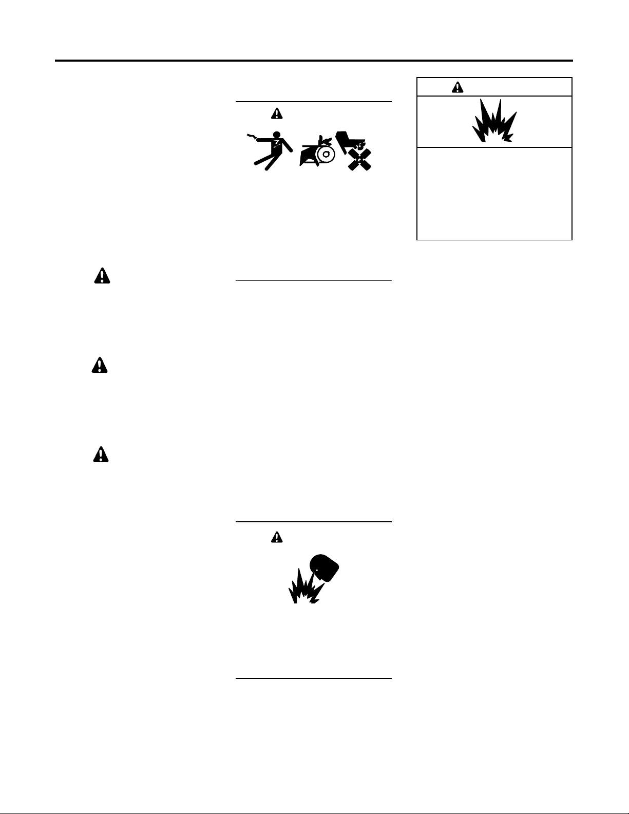
Disabling the generator set.
Accidental starting can cause
severe injury or death. Before
working on the generator set or
connected equipment, disable the
generator set as follows: (1) Move the
generator set master switch to the OFF
position. (2) Disconnect the power to
the battery charger. (3) Remove the
battery cables, negative (--) lead first.
Reconnect the negative (--) lead last
when reconnecting the battery. Follow
these precautions to prevent starting of
the generator set by an automatic
transfer switch, remote start/stop
switch, or engine start command from a
remote computer.
Battery
WARNING
Sulfuric acid in batteries.
Can cause severe injury or death.
Wear protective goggles and
clothing. Battery acid may cause
blindness and burn skin.
WARNING
Explosion.
Can cause severe injury or death.
Relays in the battery charger
cause arcs or sparks.
Locate the battery in a well-ventilated
area. Isolate the battery charger from
explosive fumes.
Battery electrolyte is a diluted
sulfuric acid. Battery acid can
cause severe injury or death. Battery
acid can cause blindness and burn
skin. Always wear splashproof safety
goggles, rubber gloves, and boots
when servicing the battery. Do not
open a sealed battery or mutilate the
battery case. If battery acid splashes in
the eyes or on the skin, immediately
flush the affected area for 15 minutes
with large quantities of clean water.
Seek immediate medical aid in the
case of eye contact. Never add acid to
a battery after placing the battery in
service, as this may result in
hazardous spattering of battery acid.
Battery acid cleanup. Battery acid
can cause severe injury or death.
Battery acid is electrically conductive
and corrosive. Add 500 g (1 lb.) of
bicarbonate of soda (baking soda) to a
containerwith4L(1gal.)ofwaterand
mix the neutralizing solution. Pour the
neutralizing solution on the spilled
battery acid and continue to add the
neutralizing solution to the spilled
battery acid until all evidence of a
chemical reaction (foaming) has
ceased. Flush the resulting liquid with
water and dry the area.
7Safety Precautions and InstructionsTP-6200 10/12
Page 8
Battery gases. Explosion can cause
severe injury or death. Battery gases
can cause an explosion. Do not smoke
or permit flames or sparks to occur
near a battery at any time, particularly
when it is charging. Do not dispose of a
battery in a fire. To prevent burns and
sparks that could cause an explosion,
avoid touching the battery terminals
with tools or other metal objects.
Remove all jewelry before servicing
the equipment. Discharge static
electricity from your body before
touching batteries by first touching a
grounded metal surface away from the
battery. To avoid sparks, do not disturb
the battery charger connections while
the battery is charging. Always turn the
battery charger off before
disconnecting the battery connections.
Ventilate the compartments containing
batteries to prevent accumulation of
explosive gases.
Battery short circuits. Explosion
can cause severe injury or death.
Short circuits can cause bodily injury
and/or equipment damage.
Disconnect the battery before
generator set installation or
maintenance. Remove all jewelry
before servicing the equipment. Use
tools with insulated handles. Remove
the negative (--) lead first when
disconnecting the battery. Reconnect
the negative (--) lead last when
reconnecting the battery. Never
connect the negative (--) battery cable
to the positive (+) connection terminal
of the starter solenoid. Do not test the
battery condition by shorting the
terminals together.
Engine Backfire/Flash
Fire
Servicing the fuel system. A flash
fire can cause severe injury or
death. Do not smoke or permit flames
or sparks near the carburetor, fuel line,
fuel filter, fuel pump, or other potential
sources of spilled fuels or fuel vapors.
Catch fuels in an approved container
when removing the fuel line or
carburetor.
Servicing the air cleaner. A sudden
backfire can cause severe injury or
death. Do not operate the generator
set with the air cleaner removed.
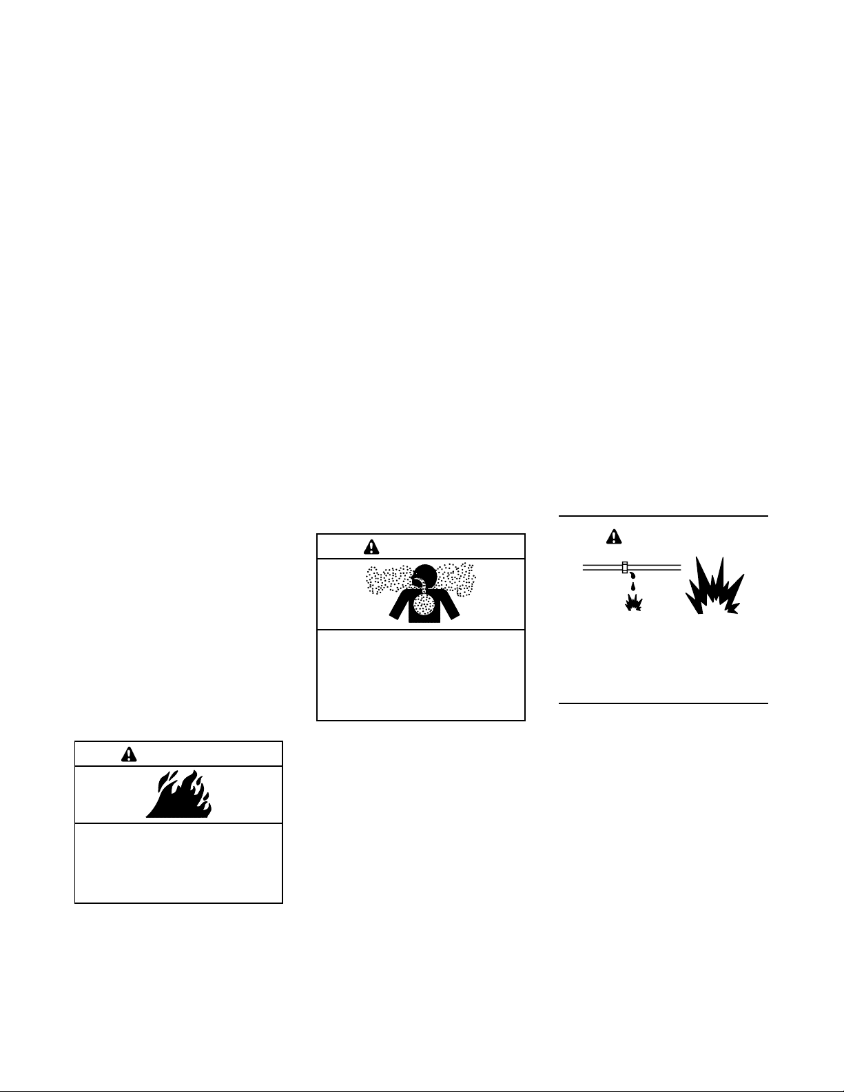
Combustible materials. A fire can
cause severe injury or death.
Generator set engine fuels and fuel
vapors are flammable and explosive.
Handle these materials carefully to
minimize the risk of fire or explosion.
Equip the compartment or nearby area
with a fully charged fire extinguisher.
Select a fire extinguisher rated ABC or
BC for electrical fires or as
recommended by the local fire code or
an authorized agency. Train all
personnel on fire extinguisher
operation and fire prevention
procedures.
Exhaust System
WARNING
Carbon monoxide.
Can cause severe nausea,
fainting, or death.
The exhaust system must be
leakproof and routinely inspected.
Carbon monoxide symptoms.
Carbon monoxide can cause severe
nausea, fainting, or death. Carbon
monoxide is a poisonous gas present
in exhaust gases. Carbon monoxide is
an odorless, colorless, tasteless,
nonirritating gas that can cause death if
inhaled for even a short time. Carbon
monoxide poisoning symptoms
include but are not limited to the
following:
D Light-headedness, dizziness
D Physical fatigue, weakness in
joints and muscles
D Sleepiness, mental fatigue,
inability to concentrate
or speak clearly, blurred vision
D Stomachache, vomiting, nausea
If experiencing any of these symptoms
and carbon monoxide poisoning is
possible, seek fresh air immediately
and remain active. Do not sit, lie down,
or fall asleep. Alert others to the
possibility of carbon monoxide
poisoning. Seek medical attention if
the condition of affected persons does
not improve within minutes of breathing
fresh air.
Fuel System
WARNING
Explosive fuel vapors.
Can cause severe injury or death.
Use extreme care when handling,
storing, and using fuels.
WARNING
Fire.
Can cause severe injury or death.
Do not smoke or permit flames or
sparks near fuels or the fuel system.
8 Safety Precautions and Instructions TP-6200 10/12
Generator set operation. Carbon
monoxide can cause severe
nausea, fainting, or death. Carbon
monoxide is an odorless, colorless,
tasteless, nonirritating gas that can
cause death if inhaled for even a short
time. Avoid breathing exhaust fumes
when working on or near the generator
set. Never operate the generator set
inside a building unless the exhaust
gas is piped safely outside. Never
operate the generator set where
exhaust gas could accumulate and
seep back inside a potentially occupied
building.
Page 9
The fuel system. Explosive fuel
vapors can cause severe injury or
death. Vaporized fuels are highly
explosive. Use extreme care when
handling and storing fuels. Store fuels
inawell-ventilatedareaawayfrom
spark-producing equipment and out of
the reach of children. Never add fuel to
the tank while the engine is running
because spilled fuel may ignite on
contact with hot parts or from sparks.
Do not smoke or permit flames or
sparks to occur near sources of spilled
fuel or fuel vapors. Keep the fuel lines
and connections tight and in good
condition. Do not replace flexible fuel
lines with rigid lines. Use flexible
sections to avoid fuel line breakage
caused by vibration. Do not operate
the generator set in the presence of
fuel leaks, fuel accumulation, or
sparks. Repair fuel systems before
resuming generator set operation.
Explosive fuel vapors can cause
severe injury or death. Ta k e
additional precautions when using the
following fuels:
Gasoline—Store gasoline only in
approved red containers clearly
marked GASOLINE.
Propane (LP)—Adequate ventilation
is mandatory. Because propane is
heavier than air, install propane gas
detectors low in a room. Inspect the
detectors per the manufacturer’s
instructions.
Natural Gas—Adequate ventilation is
mandatory. Because natural gas rises,
install natural gas detectors high in a
room. Inspect the detectors per the
manufacturer’s instructions.
Fuel tanks. Explosive fuel vapors
can cause severe injury or death.
Gasoline and other volatile fuels stored
in day tanks or subbase fuel tanks can
cause an explosion. Store only diesel
fuel in tanks.
Draining the fuel system. Explosive
fuel vapors can cause severe injury
or death. Spilled fuel can cause an
explosion. Use a container to catch
fuel when draining the fuel system.
Wipe up spilled fuel after draining the
system.
Gas fuel leaks. Explosive fuel
vapors can cause severe injury or
death. Fuel leakage can cause an
explosion. Check the LP vapor gas or
natural gas fuel system for leakage by
using a soap and water solution with
the fuel system test pressurized to
6--8 ounces per square inch
(10--14 inches water column). Do not
use a soap solution containing either
ammonia or chlorine because both
prevent bubble formation. A
successful test depends on the ability
of the solution to bubble.
LP liquid withdrawal fuel leaks.
Explosive fuel vapors can cause
severe injury or death. Fuel leakage
can cause an explosion. Check the LP
liquid withdrawal gas fuel system for
leakage by using a soap and water
solution with the fuel system test
pressurized to at least 90 psi
(621 kPa). Do not use a soap solution
containing either ammonia or chlorine
because both prevent bubble
formation. A successful test depends
on the ability of the solution to bubble.
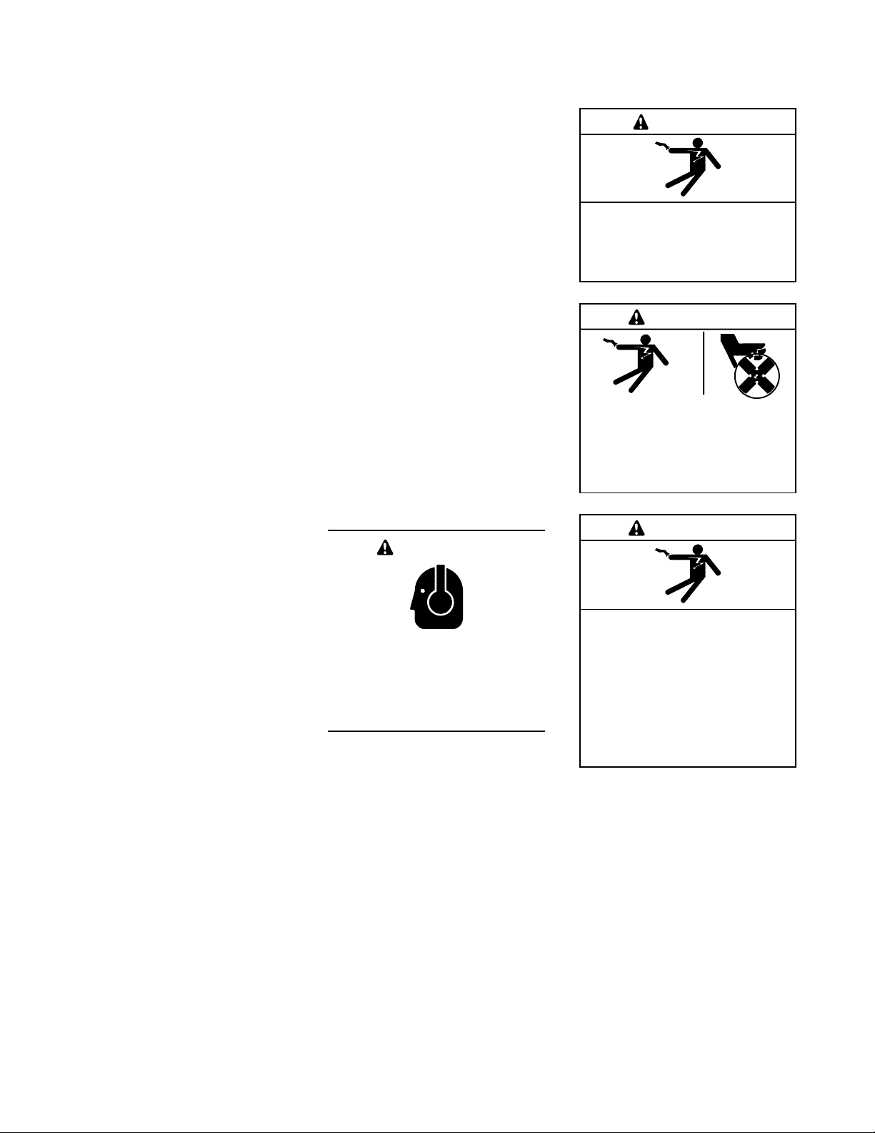
Hazardous Noise
CAUTION
Hazardous noise.
Can cause hearing loss.
Never operate the generator set
without a muffler or with a faulty
exhaust system.
Engine noise. Hazardous noise can
cause hearing loss. Generator sets
not equipped with sound enclosures
can produce noise levels greater than
105 dBA. Prolonged exposure to
noise levels greater than 85 dBA can
cause permanent hearing loss. Wear
hearing protection when near an
operating generator set.
Hazardous Voltage/
Moving Parts
DANGER
Hazardous voltage.
Will cause severe injury or death.
Disconnect all power sources before
opening the enclosure.
WARNING
Hazardous voltage.
Can cause severe injury or death.
Operate the generator set only when
all guards and electrical enclosures
areinplace.
WARNING
Hazardous voltage.
Backfeed to the utility system can
cause property damage, severe
injury, or death.
If the generator set is used for
standby power, install an automatic
transfer switch to prevent inadvertent
interconnection of standby and
normal sources of supply.
Grounding electrical equipment.
Hazardous voltage can cause
severe injury or death. Electrocution
is possible whenever electricity is
present. Ensure you comply with all
applicable codes and standards.
Electrically ground the generator set,
transfer switch, and related equipment
and electrical circuits. Turn off the
main circuit breakers of all power
sources before servicing the
equipment. Never contact electrical
leads or appliances when standing in
water or on wet ground because these
conditions increase the risk of
electrocution.
Moving parts.
9Safety Precautions and InstructionsTP-6200 10/12
Page 10
High voltage test. Hazardous
voltage can cause severe injury or
death. Follow the instructions of the
test equipment manufacturer when
performing high-voltage tests on the
rotor or stator. An improper test
procedure can damage equipment or
lead to generator set failure.
Testing the photo transistor circuit
board. Hazardous voltage can
cause severe injury or death. When
the end cover is removed, do not
expose the photo transistor circuit
board mounted on the generator set
end bracket to any external light
source, as exposure to light causes
high voltage. Keep foreign sources of
light away from the photo transistor
circuit board during testing. Place
black electrical tape over the LED on
the circuit board before starting the
generator set.
Installing the photo transistor
circuit board. Hazardous voltage
can cause severe injury or death.
Ensure that the foil side of the photo
transistor circuit board, the end of the
shaft, and the threaded holes are clean
and free of metal particles and chips.
Metal debris may short-circuit the
photo transistor circuit board and
cause hazardous voltage in the
generator set. Do not reconnect the
generator set to the load until the AC
voltmeter shows the correct output.
Installing the battery charger.
Hazardous voltage can cause
severe injury or death. An
ungrounded battery charger may
cause electrical shock. Connect the
battery charger enclosure to the
ground of a permanent wiring system.
As an alternative, install an equipment
grounding conductor with circuit
conductors and connect it to the
equipment grounding terminal or the
lead on the battery charger. Install the
battery charger as prescribed in the
equipment manual. Install the battery
charger in compliance with local codes
and ordinances.
Servicing the day tank. Hazardous
voltage can cause severe injury or
death. Service the day tank electrical
control module (ECM) as prescribed in
the equipment manual. Disconnect the
power to the day tank before servicing.
Press the day tank ECM OFF
pushbutton to disconnect the power.
Notice that line voltage is still present
within the ECM when the POWER ON
light is lit. Ensure that the generator set
and day tank are electrically grounded.
Do not operate the day tank when
standing in water or on wet ground
because these conditions increase the
risk of electrocution.
Short circuits. Hazardous
voltage/current can cause severe
injury or death. Short circuits can
cause bodily injury and/or equipment
damage. Do not contact electrical
connections with tools or jewelry while
making adjustments or repairs.
Remove all jewelry before servicing
the equipment.
Engine block heater. Hazardous
voltage can cause severe injury or
death. The engine block heater can
cause electrical shock. Remove the
engine block heater plug from the
electrical outlet before working on the
block heater electrical connections.
Handling the capacitor. Hazardous
voltage can cause severe injury or
death. Electrical shock results from
touching the charged capacitor
terminals. Discharge the capacitor by
shorting the terminals together.
(Capacitor-excited models only)
Electrical backfeed to the utility.
Hazardous backfeed voltage can
cause severe injury or death. Install
a transfer switch in standby power
installations to prevent the connection
of standby and other sources of power.
Electrical backfeed into a utility
electrical system can cause severe
injury or death to utility personnel
working on power lines.
Testing live electrical circuits.
Hazardous voltage or current can
cause severe injury or death. Have
trained and qualified personnel take
diagnostic measurements of live
circuits. Use adequately rated test
equipment with electrically insulated
probes and follow the instructions of
the test equipment manufacturer when
performing voltage tests. Observe the
following precautions when performing
voltage tests: (1) Remove all jewelry.
(2) Stand on a dry, approved
electrically insulated mat. (3) Do not
touch the enclosure or components
inside the enclosure. (4) Be prepared
for the system to operate automatically.
(600 volts and under)
WARNING
Airborne particles.
Can cause severe injury or
blindness.
Wear protective goggles and clothing
when using power tools, hand tools,
or compressed air.
Servicing the generator set when it
is operating. Exposed moving parts
can cause severe injury or death.
Keep hands, feet, hair, clothing, and
test leads away from the belts and
pulleys when the generator set is
running. Replace guards, screens,
and covers before operating the
generator set.
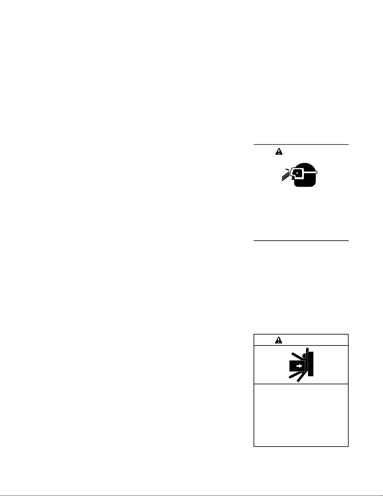
Heavy Equipment
WARNING
Connecting the battery and the
battery charger. Hazardous voltage
can cause severe injury or death.
Reconnect the battery correctly,
positive to positive and negative to
negative, to avoid electrical shock and
damage to the battery charger and
battery(ies). Have a qualified
electrician install the battery(ies).
10 Safety Precautions and Instructions TP-6200 10/12
Unbalanced weight.
Improper lifting can cause severe
injury or death and equipment
damage.
Do not use lifting eyes.
Lift the generator set using lifting bars
inserted through the lifting holes on
the skid.
Page 11
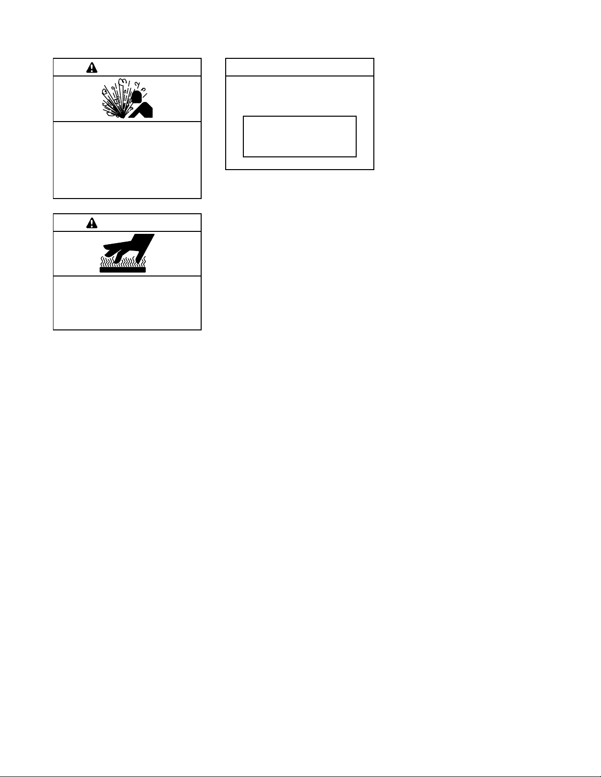
Hot Parts
Notice
WARNING
Hot coolant and steam.
Can cause severe injury or death.
Before removing the pressure cap,
stop the generator set and allow it to
cool. Then loosen the pressure cap
to relieve pressure.
WARNING
Hot engine and exhaust system.
Can cause severe injury or death.
Do not work on the generator set until
it cools.
Servicing the alternator. Hot parts
can cause severe injury or death.
Avoid touching the alternator field or
exciter armature. When shorted, the
alternator field and exciter armature
become hot enough to cause severe
burns.
NOTICE
This generator set has been
rewired from its nameplate voltage
to
246242
NOTICE
Voltage reconnection. Affix a notice
to the generator set after reconnecting
the set to a voltage different from the
voltage on the nameplate. Order
voltage reconnection decal 246242
from an authorized service
distributor/dealer.
NOTICE
Canadian installations only.For
standby service connect the output of
the generator set to a suitably rated
transfer switch in accordance with
Canadian Electrical Code, Part 1.
Servicing the exhaust system. Hot
parts can cause severe injury or
death. Do not touch hot engine parts.
The engine and exhaust system
components become extremely hot
during operation.
11Safety Precautions and InstructionsTP-6200 10/12
Page 12

Notes
12 Safety Precautions and Instructions TP-6200 10/12
Page 13

Introduction
This manual provides operation instructions for 20 kW
and larger generator sets equipped with the following
controller:
D Decisionr 550, Software (Code) Version 2.10 or
higher
Version2.10 refers to the controller application software.
To determine the generator set controller software
version, go to Menu 20—Factory Setup and scroll down
to Code Version. The code version is the controller
software version.
Wiring diagram manuals are available separately. Refer
to the engine operation manual for generator set engine
scheduled maintenance information.
Information in this publication represents data available
at the time of print. Kohler Co. reserves the right to
change this publication and the products represented
without notice and without any obligation or liability
whatsoever.
Read this manual and carefully follow all procedures and
safety precautions to ensure proper equipment
operation and to avoid bodily injury. Read and follow the
Safety Precautions and Instructions section at the
beginning of this manual. Keep this manual with the
equipment for future reference.
The equipment service requirements are very important
to safe and efficient operation. Inspect the parts often
and perform required service at the prescribed intervals.
Maintenance work must be performed by appropriately
skilled and suitably trained maintenance personnel
familiar with generator set operation and service.
The disk supplied with this generator set is a backup
copy of the generator set personality program
containing data specific to the engine and alternator.
The engine and alternator data was preprogrammed in
the controller at the factory and no further use of the disk
should be necessary. Typically, your authorized
distributor stores this disk for possible future use such as
controller replacement or other circumstances requiring
a backup.
Abbreviations
This publication makes use of numerous abbreviations.
Typically, the word(s) are spelled out along with the
abbreviation in parentheses when shown for the first
time in a section. Appendix A, Abbreviations, also
includes many abbreviation definitions.
List of Related Materials
Separate literature contains communication and
software information not provided in this manual.
Figure 1 lists the available literature part numbers.
Communication and Software
Manual Description
550 Controller Spec Sheet
Generator Set/Controller
Wiring Diagram Manual
550 Communications Spec Sheet
Monitor III Converters, Connections,
and Controller Setup
Monitor III Software Spec Sheet G6-76
Monitor III Converter,
Modbusr/Ethernet Spec Sheet
Monitor III Software Operation Manual TP-6347
Modbusr Communications Protocol
Operation Manual
Setup and Application Manual TP-6140
Service Parts Controllers TP-6780
Program Loader Software Installation TT-1285
SiteTecht Software Operation Manual
Remote Serial Annunciator (RSA) TT-1377
Remote Serial Annunciator (RSA II) TT-1485
Controller Service Replacement TT-1310
Figure 1 Related Literature
Literature Part No.
G6-46
Multiple Part Numbers
Contact your
Distributor/Dealer
G6-50
TT-1405
G6-79
TP-6113
TP-6701
Modbusr is a registered trademark of Schneider Electric.
13IntroductionTP-6200 10/12
Page 14

Service Assistance
For professional advice on generator set power
requirements and conscientious service, please contact
your nearest Kohler distributor or dealer.
D Consult the Yellow Pages under the heading
Generators—Electric.
D Visit the Kohler Power Systems website at
KohlerPower.com.
D Look at the labels and stickers on your Kohler product
or review the appropriate literature or documents
included with the product.
D Call toll free in the US and Canada 1-800-544-2444.
D Outside the US and Canada, call the nearest regional
office.
Headquarters Europe, Middle East, Africa
(EMEA)
Kohler Power Systems
3 rue de Brennus
93200 Saint Denis
France
Phone: (33) 1 49 178300
Fax: (33) 1 49 178301
Asia Pacific
Power Systems Asia Pacific Regional Office
Singapore, Republic of Singapore
Phone: (65) 6264-6422
Fax: (65) 6264-6455
China
North China Regional Office, Beijing
Phone: (86) 10 6518 7950
(86) 10 6518 7951
(86) 10 6518 7952
Fax: (86) 10 6518 7955
East China Regional Office, Shanghai
Phone: (86) 21 6288 0500
Fax: (86) 21 6288 0550
India, Bangladesh, Sri Lanka
India Regional Office
Bangalore, India
Phone: (91) 80 3366208
(91) 80 3366231
Fax: (91) 80 3315972
Japan, Korea
North Asia Regional Office
Tokyo, Japan
Phone: (813) 3440-4515
Fax: (813) 3440-2727
Latin America
Latin America Regional Office
Lakeland, Florida, USA
Phone: (863) 619-7568
Fax: (863) 701-7131
14 Service Assistance TP-6200 10/12
Page 15
Section 1 Specifications and Features
1.1 Introduction
The spec sheets for each generator set provide modelspecific generator and engine information. The
controller spec sheet provides specifications for this
controller. Refer to the respective spec sheet for data
not supplied in this manual. Consult the generator set
service manual, installation manual, engine operation
manual, and engine service manual for additional
specifications.
1.2 Controller Features
The controller features include the annunciator lamps,
digital display and keypad, switches and controls, and
fuses and terminal strip. The following paragraphs detail
the features by general topics.
124 5
3
The controller features, accessories, and menu displays
depend upon the engine electronic control module
(ECM) setup and features. Controller features apply to
generator set models with ECM and non-ECM engines
unless otherwise noted.
Note: Press any key on the keypad to turn on the
controller lights and display. The lights and
display turn off 5 minutes after the last keypad
entry.
Note: Measurements display in metric or English. Use
Menu 7—Generator System to change the
measurement display.
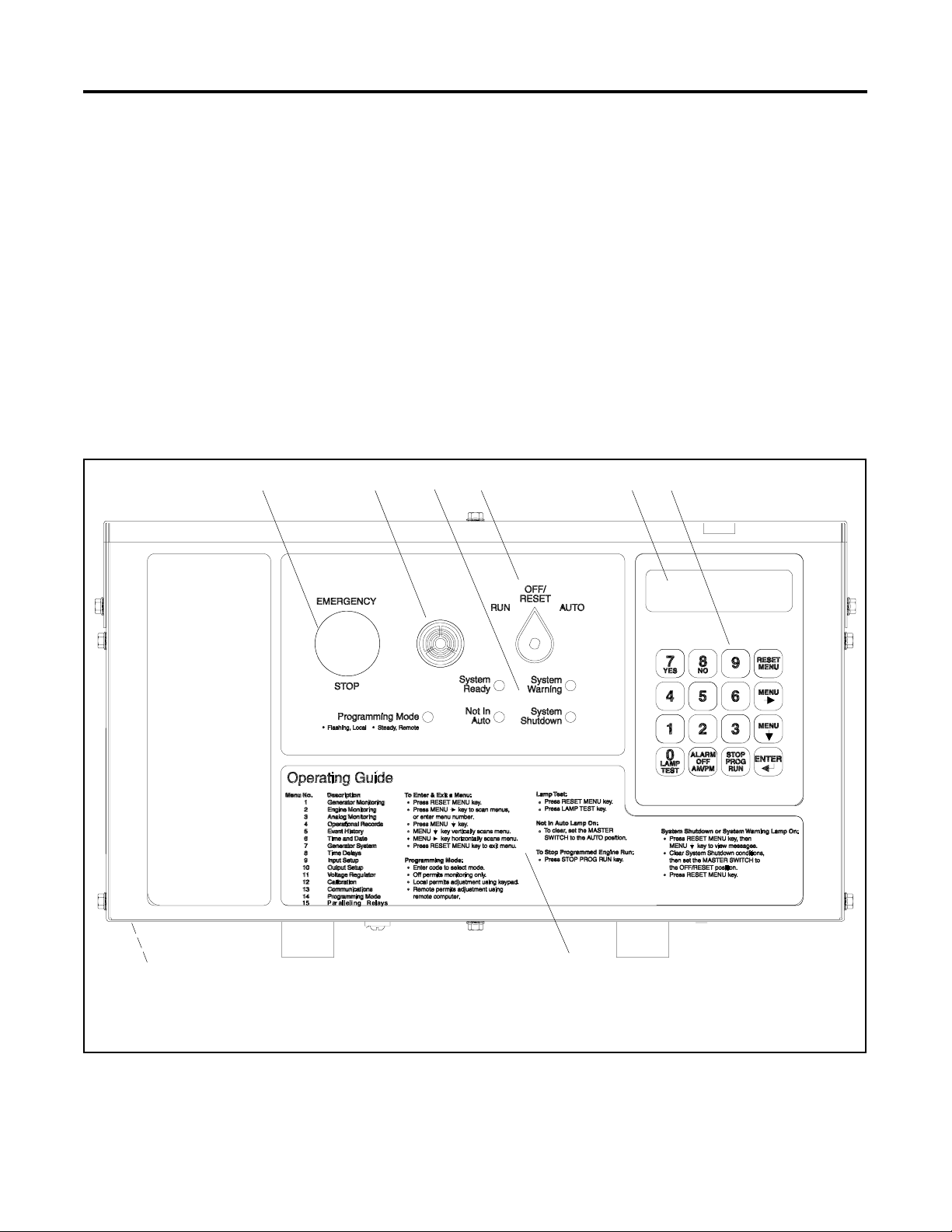
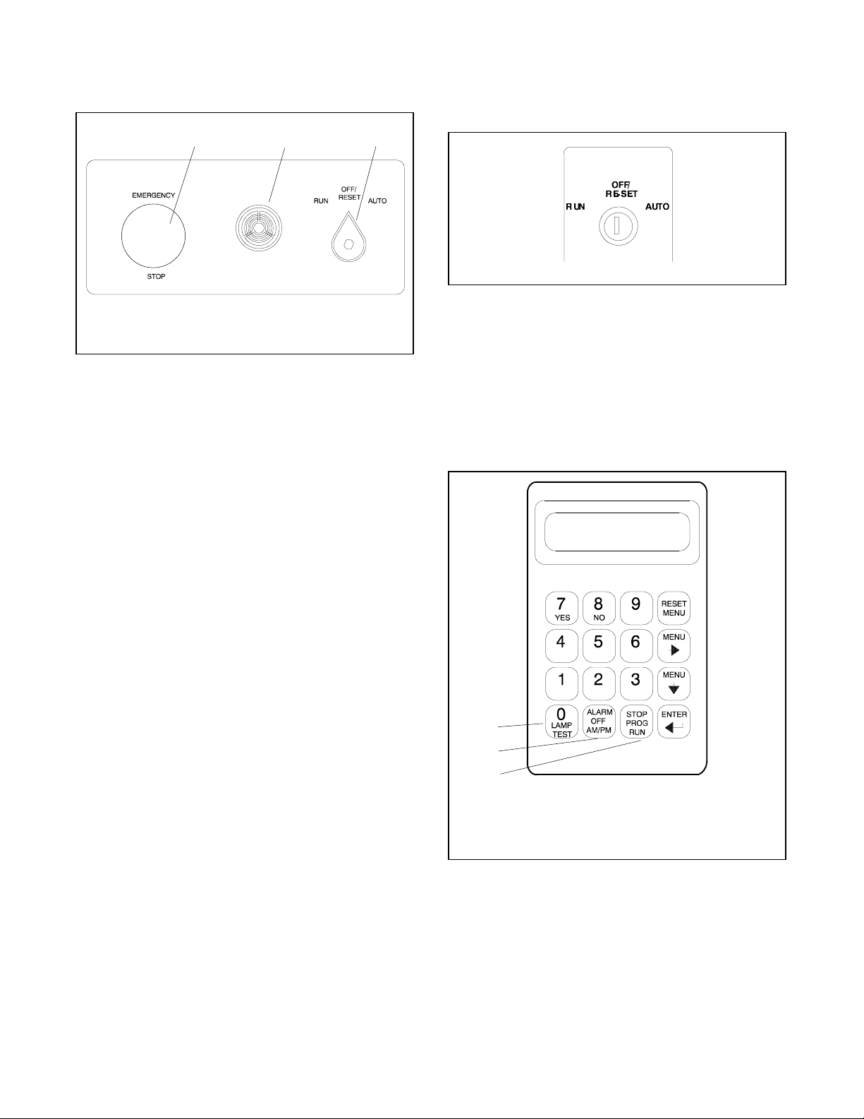
See Figure 1-1 for an illustration of the controller front
panel. See Figure 1-2 for an illustration of the controller
with the keyswitch option.
6
8
1. Emergency stop switch
2. Alarm horn (see keypad for alarm silence)
3. Annunciator lamps (see keypad for lamp test)
4. Generator set master switch, run/off-reset/auto positions
5. Digital display
6. Keypad
7. Operating guide
8. Controller terminal strips (on circuit board)
7
Figure 1-1 550 Controller with Three-Position Selector Switch
TP-6200 10/12 15Section 1 Specifications and Features
TP-6083-2
Page 16
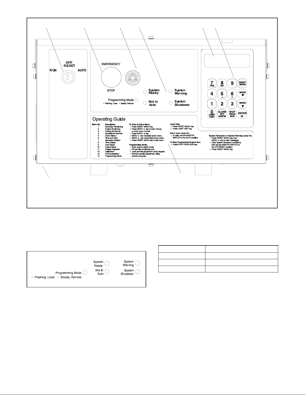
12 4 5
3
6
8
1. Generator set master switch, run/off-reset/auto positions
(keyswitch option)
2. Emergency stop switch
3. Alarm horn (see keypad for alarm silence)
4. Annunciator lamps (see keypad for lamp test)
Figure 1-2 550 Controller with Keyswitch Option
1.2.1 Annunciator Lamps
Five annunciator lamps provide visual generator set
status. See Figure 1-3.
TP-6083-2
Figure 1-3 Annunciator Lamps
System Ready. Green lamp illuminates when the
generator set master switch is in the AUTO (automatic
start) position and the system senses no faults. The unit
is ready to start.
TP-6083-2
7
5. Digital display
6. Keypad
7. Operating guide
8. Controller terminal strips (on circuit board)
Programming Mode. Yellow programming lamp
indicates the user selected programming mode. See
Figure 1-4.
Programming Lamp Programming Mode Selection
Lamp Flashing Local Programming
Lamp Steady On Remote Programming
Lamp Off Programming Disabled
Figure 1-4 Programming Lamp Mode
Note: Find additional information for the programming
mode lamp function and access to the local or
remote programming modes in Section 2.8, Local
Programming Mode On, Menu 14—Programming
Mode.
Not in Auto (NIA). Yellow lamp illuminates when the
generator set master switch is not in the AUTO
(automatic start) position.
TP-6200 10/1216 Section 1 Specifications and Features
Page 17

System Warning. Yellow lamp identifies an existing
fault condition that does not shut down the generator set.
A continuing system warning fault condition may cause
a system shutdown. Correct all system warnings as
soon as practical.
System Shutdown. Red lamp indicates that the
generator set has shut down because of a fault
condition. The unit will not start without resetting the
controller, see Section 2.3.7, Controller Reset
Procedure.
See Section 2.3.5, System Warning Lamp, for
definitions of the items listed.
The following conditions cause a system warning:
D Engine functions:
d ECM yellow alarm
(DDC/MTU engine with MDEC/ADEC)
d High battery voltage
d High coolant temperature
d Low battery voltage
d Low coolant temperature
d Low fuel (level or pressure)*
d Low oil pressure
d Speed sensor fault
d Starting aid (system status)
d Weak battery
D General functions:
d Auxiliary—Analog up to 7 user-selectable inputs
each with a high and low programmable warning
level
d Auxiliary—Digital up to 21 user-selectable
warnings
d Battery charger fault*
d Emergency power system (EPS) supplying load
d Engine cooldown delay
d Engine start delay
d Load shed kW overload
d Load shed underfrequency
d Master switch not in AUTO (automatic start)
position
d NFPA 110 fault (National Fire Protection
Association)
d System ready (system status)
D Alternator functions:
d AC sensing loss
d Ground fault*
d Overcurrent
* Requires optional input sensors.
Note: See Figure 2-8 in User Inputs for factory-
reserved analog and digital inputs that are not
user-selectable.
See Section 2.3.6, System Shutdown Lamp, for
definitions of the items listed.
The following conditions cause a system shutdown:
D Engine functions:
d Air damper closed (status), if equipped
d Coolant temperature signal loss
d ECM red alarm
(DDC/MTU engine with MDEC/ADEC)
d Engine stalled (ECM only)
d High coolant temperature
d High oil temperature
d Low coolant level
d Low oil pressure
d Oil pressure signal loss
d Overcrank
d Overspeed
D General functions:
d Auxiliary—Analog up to 7 user-selectable inputs
each with a high and low programmable
shutdown level
d Auxiliary—Digital up to 21 user-selectable
shutdowns
d ECM communications loss (ECM models only)
d Emergency stop
d Internal fault
d Master switch in OFF/RESET position
d Master switch error
d Master switch open
d NFPA 110 fault
D Alternator functions:
d AC output overvoltage
d AC output undervoltage
d Alternator protection against overload and short
circuits
d Field overvoltage
(M4, M5, M7, or M10 alternator only)
d Locked rotor (failed to crank)
d Overfrequency
d Underfrequency
Note: See Figure 2-8 in User Inputs for factory-
reserved analog and digital inputs which are
not user-selectable.
TP-6200 10/12 17Section 1 Specifications and Features
Page 18
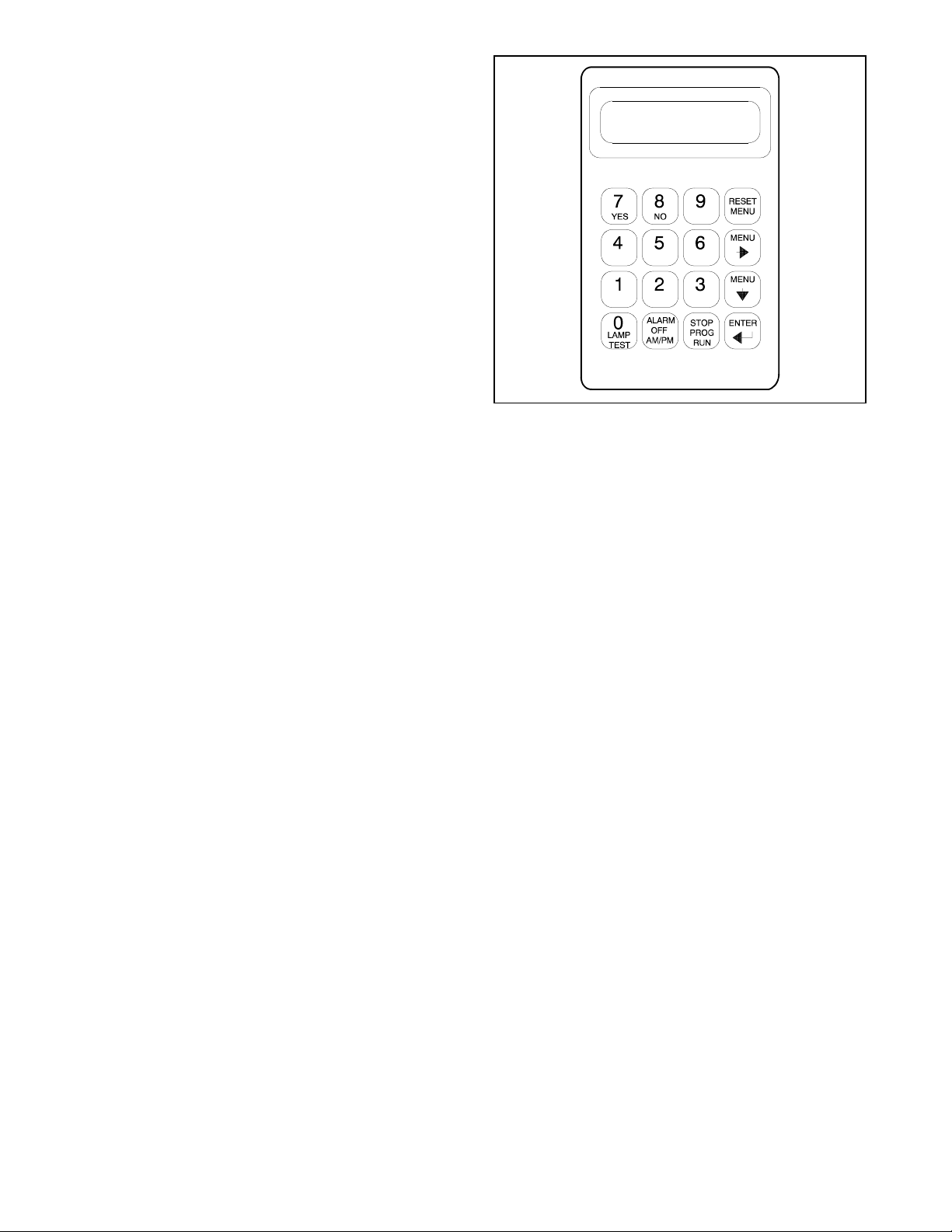
1.2.2 Digital Display and Keypad
Figure 1-5 illustrates the digital display and keypad.
Note: Press any key on the keypad to turn on the
controller lights and display. The lights and
display turn off 5 minutes after the last keypad
entry.
The 2-line vacuum fluorescent display provides
generator set and engine condition information.
The 16-button keypad gives the user information access
and local programming capability.
Keypad Functions
Alarm (Horn) Off key silences the alarm horn at the
operator’s discretion. Place the generator set master
switch in the AUTO position before silencing the alarm
horn. See Section 2.3.7, Controller Reset Procedure,
and Section 1.2.3, Switches and Controls.
TP-5829-2
Figure 1-5 Digital Display and Keypad
AM/PM key provides time of day data entries when
programming.
Enter ↵ key provides confirmation entry when selecting
menu or programming.
Lamp Test key tests the controller indicator lamps,
horn, and digital display. See Section 1.2.3, Switches
and Controls.
Menu down ↓ key provides navigation within menus
when necessary.
Menu right → key provides navigation within menus
when necessary.
Numeric 0--9 keys provide numeric data entries when
selecting menus or programming.
Reset Menu key exits a menu, clears incorrect entries,
and cancels the auto-scroll feature.
Stop Prog (Program) Run key allowstheusertostop
any previously programmed generator set run
sequence. See Section 1.2.3, Switches and Controls.
Yes/No keys provides data answer entries when
programming.
Alternator Output Displays (Menu 1)
AC Amps displays the alternator output current. The
display shows each line of 3-phase models.
AC Volts displays the alternator output voltages. The
display shows all line-to-neutral and line-to-line voltage
combinations.
Alternator Duty Level displays the actual load kW
divided by the nameplate kW rating as a percentage.
Frequency displays the frequency (Hz) of alternator
output voltage.
Hourmeter displays the generator set operating hours
loaded and unloaded for reference in scheduling
maintenance.
KVA displays the total and individual L1, L2, and L3 kVA.
KVAR displays the total and individual L1, L2, and L3
kVAR.
Power Factor displays the kW/kVA and the individual
line power factor values.
Watts displays the total and individual L1, L2, and L3
kilowatts.
TP-6200 10/1218 Section 1 Specifications and Features
Page 19

Engine Displays (Menu 2)
Some engine displays are available with selected
generator set engines using engine ECMs only. The
controller display shows N/A (not available) for items
that are unavailable. See the controller spec sheet for
applicable generator set models.
Ambient Temperature displays the generator set area
ambient temperature.
Charge Air Pressure displays the engine turbocharger
boost air pressure.
Charge Air Temperature displays the engine
turbocharger boost air temperature.
Coolant Level displays the engine coolant level.
Coolant Pressure displays the engine coolant
pressure.
Coolant Temperature displays the engine coolant
temperature.
Event History displays up to 100 stored system events
including status, warnings, and shutdowns.
Last Start Date displays the date when the generator
set last operated.
Number of Starts displays the total number of
generator set startup events.
Number of Starts (Since) Last Maintenance displays
the total number of generator set startup events since
the last maintenance date.
Operating Days (Since) Last Maintenance displays
the total number of days of operation since the last
maintenance date. A counted day of operation can be
1--24 hours.
Run Time displays the total loaded hours, total
unloaded hours, and total kW hours.
Run Time Since Maintenance displays the total loaded
hours, total unloaded hours, and total kW hours.
Crankcase Pressure displays the engine crankcase
pressure.
DC Volts displays the voltage of starting battery(ies).
Fuel Pressure displays the fuel supply pressure.
Fuel Rate displays the calculated fuel consumption rate
based on fuel injector outputs.
Fuel Temperature displays the fuel supply
temperature.
Oil Level displays the engine oil level as a percent of full
capacity.
Oil Pressure displays the engine oil pressure.
Oil Temperature displays the engine oil temperature.
RPM (Tachometer) displays the engine speed.
Used Last Run displays the accumulated amount of
fuel used since last reset by the engine DDEC reader.
Operational Record Displays (Menus 4 and 5)
The operational record displays events since last reset.
See Section 2.8.4, Menu 4—Operational Records, for
resetting procedure.
Time Delay Displays (Menu 8)
The time delays are user adjustable. See Section 2.8.8,
Menu 8—TIme Delays, for time delay adjustments. See
Section 1.3.1, Status Event and Fault Specifications, for
range and default settings.
Crank On/Crank Pause displays the time allocated for
generator set crank on and crank pause in
minutes:seconds.
Engine Cooldown displays the time delay for engine
cooldown while the master switch is in the AUTO or RUN
positions and not in the idle mode.
Engine Start displays the time delay before the
generator set starts while the master switch is in AUTO
or RUN positions.
Overcrank Shutdown (Number of) Crank Cycles
displays the number of unsuccessful crank cycles
(crank on/crank pause) before the generator set shuts
down on an overcrank fault.
Overvoltage displays the time delay before the
generator set shuts down because of an overvoltage
condition.
Starting Aid displays the engine starting aid activation
time.
Engine Start Countdown displays the time remaining
before the next generator set startup.
TP-6200 10/12 19Section 1 Specifications and Features
Undervoltage displays the time delay before the
generator set shuts down because of an undervoltage
condition.
Page 20
1.2.3 Switches and Controls
See Figure 1-6 and Figure 1-8 for switches and controls.
123
TP-6083-2
1. Emergency stop switch
2. Alarm horn
3. Generator set master switch
Figure 1-6 Switches and Alarm Horn
Note: Find additional switches and controls in
Section 2.5.1, Keypad Operation.
Alarm Horn. The alarm horn alerts the operator or other
attendants that a shutdown or warning condition exists.
See Section 1.3, Controller Logic Specifications, for
conditions. Place the generator set master switch in the
AUTO position before silencing the alarm horn. The
alarm horn cannot be silenced unless the generator set
master switch is in the AUTO position. See
Section 2.3.7, Controller Reset Procedure.
The generator set master switch with the keyswitch
option (Figure 1-7) is available to meet appropriate local
code requirements. The key is removable in the AUTO
position only.
TP-6083-2
Figure 1-7 Generator Set Master Switch with
Keyswitch Option
Lamp Test. The keypad switch tests the controller
indicator lamps, horn, and digital display. Press the
reset menu key before pressing the lamp test key.
Stop Prog (Program) Run. Keypad switch allows the
user to stop any previously programmed generator set
run sequence.
Alarm (Horn) Off. The keypad switch silences the
alarm horn at the operator’s discretion. Place the
generator set master switch in the AUTO position before
silencing the alarm horn. Restore alarm horn switches
at all locations including those on remote annunciator
and audiovisual alarm kits to the normal position after
correcting the fault shutdown to avoid reactivating the
alarm horn. See Section 2.3.7, Controller Reset
Procedure.
AM/PM. This keypad switch provides time of day data
entries when programming.
Emergency Stop. The operator-activated pushbutton
immediately shuts down the generator set in emergency
situations. Reset the emergency stop switch after
shutdown by pulling the switch knob outward. Use the
emergency stop switch for emergency shutdowns only.
Use the generator set master switch for normal
shutdowns.
Generator Set Master Switch (Run/Off-Reset/Auto).
This switch resets the controller fault lamps and
start/stops the generator set. Refer to Section 2.3.1,
Starting, Section 2.3.2, Stopping, and Section 2.3.3,
Emergency Stop Switch Reset Procedure.
1
2
3
1. Lamp test
2. Alarm horn silence
3. Stop program run
Figure 1-8 Keypad Switches
TP-5829-2
TP-6200 10/1220 Section 1 Specifications and Features
Page 21
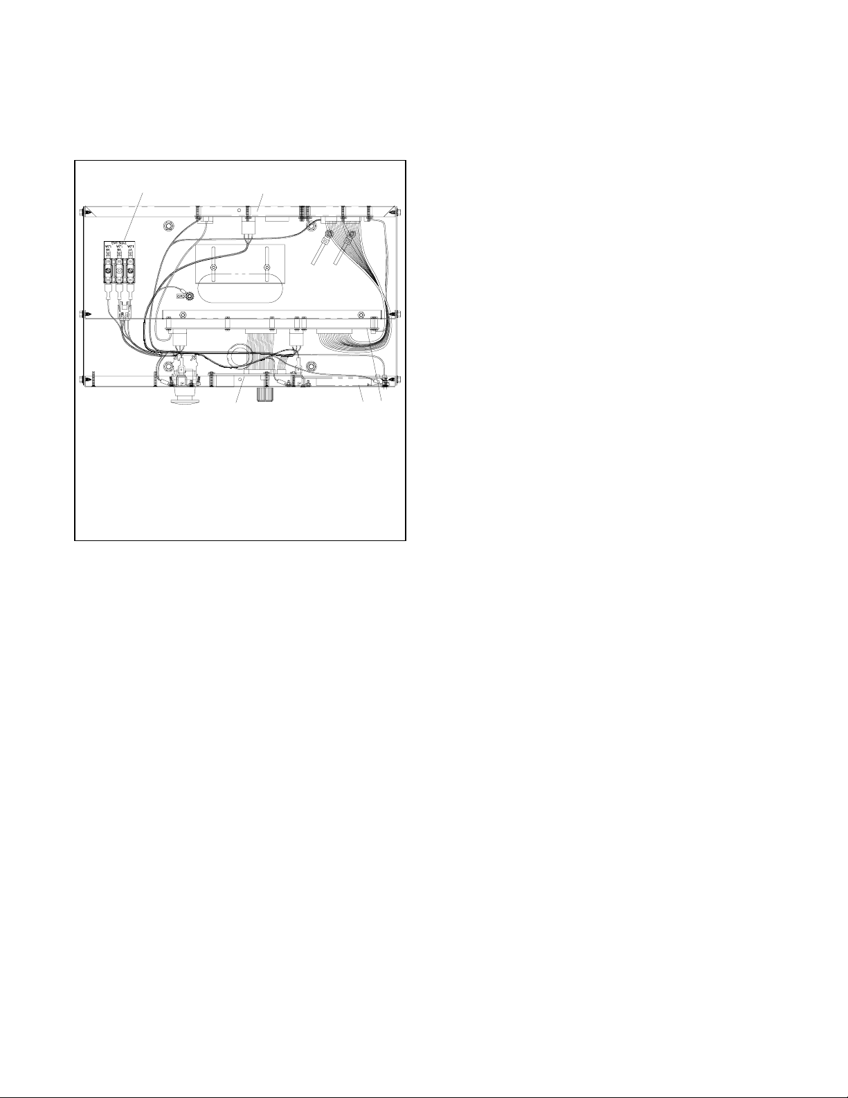
1.2.4 Controller Circuit Boards
1.2.5 Fuses
The controller has five circuit boards—indicator,
interconnection, keypad, digital display, and main logic/
communication. See Figure 1-9 for circuit board
locations.
12
5
1. AC fuse block (TB5)
2. Interconnection circuit board TB1, TB2, TB3, and TB4
terminal strips and F1, F2, and F3 fuses
3. Main logic (microprocessor)/communication circuit board
4. Keypad and digital display circuit boards
5. Indicator circuit board (LED and alarm horn)
34
GM10193B-A
Figure 1-9 Controller Circuit Boards and Fuses
(Controller Top View)
Indicator (Status) Circuit Board includes the LED
status lamps, alarm horn, and generator set master
switch.
Interconnection Circuit Board provides the terminal
strips to connect the controller (customer) connection
board and/or dry contact kits and three DC fuses (F1, F2,
and F3). See 6.1.3 for more information.
Keypad (Switch Membrane) Circuit Board provides
the keypad to navigate the generator set displays and
enter data.
Digital Display Circuit Board provides the vacuum
fluorescent display (VFD) for monitoring the generator
set functions and output values.
Main Logic (Microprocessor)/Communication
Circuit Board provides the controller operation logic
and provides PC communication locally (direct) or
remotely (via modem) using RS-232 or RS-485
connectors.
AC Circuit Fuses (TB5). Fuses are located inside the
controller. See Figure 1-9.
D 1.5-Amp (V7) fuse protects L1 sensing input to
interconnection circuit board.
D 1.5-Amp (V8) fuse protects L2 sensing input to
interconnection circuit board.
D 1.5-Amp (V9) fuse protects L3 sensing input to
interconnection circuit board.
DC Circuit Fuses fuses are located on the controller
interconnection circuit board.
D 5-Amp Remote Annunciator (F1) fuse protects the
dry contact kit if equipped and the controller panel
lamps.
D 5-Amp Controller (F2) fuse protects the controller
circuitry.
D 15-Amp Engine and Accessories (F3) fuse protects
the engine/starting circuitry and accessories.
1.2.6 Terminal Strips and Connectors
Terminal strips and connectors for inputs and outputs
are located on the interconnection circuit board. See
Section 6, Accessories.
TB1 Input Connection Terminal Strip provides input
connections for remote start and emergency stop
(E-Stop).
TB2 Analog Input Connection Terminal Strip
provides analog input connections, including non-ECM
sensor connections.
TB3 Accessory Power Output Connection Terminal
Strips provides a generator set power supply for factory
use.
TB4 Digital Input Connection Terminal Strips
connect external devices (engine ECM and user
supplied) to the generator set digital inputs.
P23 Connector connects the interconnection circuit
board to the controller (customer) connection terminal
strip (connector P25) inside the junction box. See 6.1.3
for more information.
TP-6200 10/12 21Section 1 Specifications and Features
Page 22
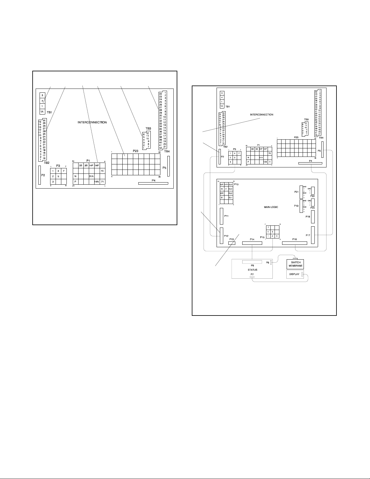
Figure 1-10 shows locations of the terminal strips on the
controller interconnection circuit board. See Section 6.2,
Accessory and Connections, for specific terminal
identification information. Refer to the wiring diagrams
for additional information on connecting accessories to
the terminal strips.
2
1
3
4
56
ADV-6533-A
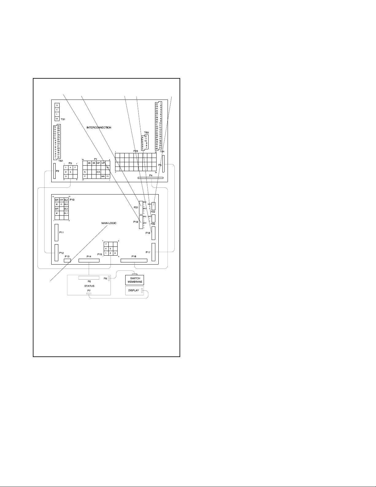
1.2.7 Circuit Board Interconnections for
Calibration Procedure
The interconnection circuit board shown in Figure 1-11
contains a ribbon connector that requires disconnection
during the calibration procedure in Menu 12—
Calibration. Disconnect ribbon connector P2 prior to
zeroing out (resetting) the auxiliary analog inputs.
1
2
1. TB1 terminal strip
2. TB2 terminal strip
3. P1 Connector
4. P23 Connector
5. TB3 terminal strip
6. TB4 terminal strip
Figure 1-10 Interconnection Circuit Board Terminal
Strips and Connectors
4
4
ADV-6533-A
1. Interconnection circuit board
2. P2 ribbon connector
3. P12 ribbon connector
4. Main logic circuit board
Figure 1-11 Interconnection Circuit Board Ribbon
Connector P2 (Top View of Circuit Board)
TP-6200 10/1222 Section 1 Specifications and Features
Page 23
1.2.8 Communication Ports
1.3 Controller Logic Specifications
The main logic circuit board contains several
communication ports for Modbusr and KBUS
connections. See Figure 1-12. Refer to the List of
Related Materials in the Introduction for corresponding
communication installation information.
12 34 5
The controller logic specifications section is an overview
of the various features and functions of the controller.
Certain features function only when optional
accessories are connected. See Section 2, Operation,
for details.
The default selection time delays and relay driver
outputs (RDOs) are factory set and adjustable with the
programming mode on (Menu 14). Some data entries
require using a PC in the Remote Programming mode.
See the monitor software operation manual for details.
Inhibit Time Delay. The inhibit time delay is the time
period following crank disconnect during which the
generator set stabilizes and the controller does not
detect a fault or status event. Select the desired inhibit
time delay from 0 to 60 seconds.
TIme Delay (Shutdown or Warning). The time delay
follows the inhibit time delay. The time delay is the time
period between when the controller first detects a fault or
status event and the controller warning or shutdown
lamp illuminates. The delay prevents any nuisance
alarms. Select the desired time delay from 0 to
60 seconds.
6
ADV-6533-A
1. P19—unused isolated connection (ISO2), RS-485 port
2. P21—KBUS isolated connection (ISO1), RS-485 port
3. P18—KBUS or Modbusr, RS-232 port
(Monitor III connection)
4. P20—Modbus, RS-485 port (Monitor III connection)
5. P22—ECM connector
6. Main logic circuit board
Figure 1-12 Main Logic Circuit Board Communication
Ports (Top View of Circuit Board)
1.3.1 Status Event and Fault
Specifications
The table starting on the next page contains all status
events and faults with ranges and time delays including
items that do not have adjustments.
Note: The engine ECM may limit the crank cycle even if
the controller is set to a longer time period.
Modbusr is a registered trademark of Schneider Electric.
TP-6200 10/12 23Section 1 Specifications and Features
Page 24

Factory-Defined Settings
Status Event
or Fault
Access Code
(password)
AC Sensing Loss 10 AC SENSING
Air Damper Control
(if used) **
Air Damper Indicator
(if used), see D20 **
Air/Fuel Module
(AFM) Engine Start
Delay ]
Air/Fuel Module
(AFM) Remote
Start]
Air/Fuel Module
(AFM) Shutdown
(see D11) ]
Alternator Protection
Shutdown
Analog Aux. Input 0 9 LOCAL BATT
Analog Aux. Inputs
A01--A07
Analog Aux. Input
A01 (non-ECM only)
Analog Aux. Input
A02 (non-ECM only)
Analog Aux. Input
A03 ]
Analog Aux. Input
A04 *
Analog Aux. Input
A04 ]
Analog Aux. Input
A06 VSG (Volvo,
GM, Doosan only)
* All models, except Waukesha-powered models. ** NFPA applications
[ Non-paralleling applications [[ DDC/MTU engine with MDEC/ADEC
] Waukesha-powered models ]] FAA only
w Paralleling applications
Refer
to
Menu
Digital Display
14 User-Selectable 0(zero)
LOSS
10
10 AFM ENG
START DELAY
10 AFM REMOTE
10 ALTERNATOR
9 USER-DEFINED
9 A01
9 A02
9 A03
9 A04
9 A04
9, 12 A06 ANALOG
START
PROTECTION
VDC
A01--A07
COOLANT
TEMP
OIL
PRESSURE
INTAKE AIR
TEMP
FUEL LEVEL
OIL TEMP
AUXILIARY IN
Relay
Driver
Output
(RDO)
RDO-25 * On Warning
RDO-25 ]
Alarm
Horn
Off
On Shutdown
On Shutdown
On Shutdown
On Shutdown
On Warning Default Values with
Off Vol vo:
Lamp Range Setting
or
Warning
or
Warning
or
Warning
Shutdown
or
Warning
Fixed
Fixed
Default Values with
Warning Enabled:
HI warning 90%
LO warning 10%
HI shutdown 100%
LO shutdown 1%
Default Values with
Warning Enabled:
HI/LO warning and
HI/LO shutdown are
all engine dependent
Default Values with
Warning Enabled:
HI/LO warning and
HI/LO shutdown are
all engine dependent
(255 psi max.)
Default Values with
Warning Enabled:
HI/LO warning and
HI/LO shutdown are
all engine dependent
Default Values with
Warning Enabled:
HI/LO warning are
engine dependent
Warning Enabled:
HI/LO warning are
engine dependent
Default
Selection
30 sec.
inhibit,
5 sec. delay
30 sec.
inhibit,
0 sec. delay
warning,
5 sec. delay
shutdown
30 sec.
inhibit,
0 sec. delay
warning,
5 sec. delay
shutdown
30 sec.
inhibit,
0 sec. delay
warning
30 sec.
inhibit,
0 sec. delay
warning
30 sec.
inhibit,
0 sec. delay
warning
0.5V=1250
4.5V=8750
GM/Doosan
60 Hz:
0.5V=2375
4.5V=2625
50 Hz:
0.5V=2327
4.5V=2624
Inhibit
Time
Delay
(sec.)
0--60 0--60
Time
Delay
(sec.)
TP-6200 10/1224 Section 1 Specifications and Features
Page 25

Factory-Defined Settings
Status Event
or Fault
Analog Aux. Input
A07
Battery Charger Fault
(see D01) **
Battle Switch
(Fault Shutdown
Override Switch)
Block Heater
Control [[
Breaker Trip w
Common Protective
Relay Output w
Critical Overvoltage
Shutdown
Cyclic Cranking 8 Off 1--6 crank cycles
Defined Common
Faults
(each input value is
set separately)
Detonation Shutdown
(see D13) ]
Detonation Warning
(see D12) ]
Digital Aux. Input
D01--D21
Digital Aux. Input
D01 Battery Charger
Fault **
Digital Aux. Input
D02 Low Fuel
Warning **
Digital Aux. Input
D03 Low Coolant
Temperature **
Digital Aux. Input
D04 Field
Overvoltage (M4,
M5, M7, or M10 alt.
only)
Digital Aux. Input
D05 Breaker
Closed w
Digital Aux. Input
D06 w
Digital Aux. Input
D09 Low Fuel
Pressure Shutdown
(125RZG only)
Digital Aux. Input
D11 Air/Fuel Module
(AFM) Shutdown ]
* All models, except Waukesha-powered models. ** NFPA applications
[ Non-paralleling applications [[ DDC/MTU engine with MDEC/ADEC
] Waukesha-powered models ]] FAA only
w Paralleling applications
Refer
to
Menu
Digital Display
9 A07
ANALOG VOLT
ADJUST
9 BATTLE
10 BLOCK HEATER
10 BREAKER
10 COMMON PR
10 CRITICAL
10 DEFINED
9, 10 USER-DEFINED
9, 10 D01 BATTERY
9, 10 D02
9, 10 D03 LOW
9, 10 D04
9, 10 D05
9, 10 D06 ENABLE
9, 10 D09
9, 10 D11
SWITCH
CONTROL
TRIP
OUTPUT
OVERVOLTAGE
COMMON
FAULT
D01--D21
CHARGER
FAULT
LOW FUEL
WARNING
COOLANT
TEMP
FIELD
OVERVOLTAGE
BREAKER
CLOSED
SYNCH
LOW FUEL
SHUTDOWN
AFM
SHUTDOWN
Relay
Driver
Output
(RDO)
RDO only
RDO-30 Off Warning
RDO-31 w
RDO-18
(lead 32A)
RDO-11
(lead 61)
RDO-08
(lead 63)
RDO-05
(lead 35)
Alarm
Horn
Off Warning Fixed
Off Warning
On Shutdown Fixed 275 volts
On Shutdown
On Shutdown
On Warning Fixed 0 sec.
On Warning Fixed 0 sec.
On Warning Fixed 0 sec.
On Shutdown Fixed 1 sec.
Off Warning Fixed 0 sec.
On Shutdown Fixed 5 sec.
On Shutdown Fixed 0 sec.
or
Warning
or
Warning
Range SettingLamp
±10% of system
voltage over the range
of 0.5--4.5 VDC
10--30 sec. crank on
1--60 sec. pause
Default shutdowns
include:
Emergency stop
High coolant temp
Low oil pressure
Overcrank
Overspeed
Default
Selection
(L1--L2)
15 sec.
15 sec.
30 sec.
inhibit,
5 sec. delay
30 sec.
inhibit,
5 sec. delay
inhibit,
0 sec. delay
inhibit,
0 sec. delay
inhibit,
0 sec. delay
inhibit,
15 sec.
delay
inhibit,
0 sec. delay
20 sec.
inhibit, 0
sec. delay
inhibit,
0 sec. delay
inhibit,
0 sec. delay
Inhibit
Time
Delay
(sec.)
3
0--60 0--60
0--60 0--60
Time
Delay
(sec.)
TP-6200 10/12 25Section 1 Specifications and Features
Page 26

Factory-Defined Settings
Status Event
or Fault
Digital Aux. Input
D12 Detonation
Warning ]
Digital Aux. Input
D13 Detonation
Sensing Module
(DSM) Shutdown ]
Digital Aux. Input
D13 Knock Detection
Module (KDM)
Shutdown ]
Digital Aux. Input D14
Low Coolant Level,
(with LCL switch) **
Digital Aux. Input
D15 Remote
Shutdown
Digital Aux. Input
D16 Remote Reset
Digital Aux. Input
D17 VAR/PF mode
Digital Aux. Input
D18 Voltage Lower
Digital Aux. Input
D19 Voltage Raise
Digital Aux. Input
D20 Air Damper
Indicator (if used) **
Digital Aux. Input
D21 Idle (speed)
Mode Function
ECM Red Alarm
(was MDEC Red
Alarm) [[
ECM Yellow Alarm
(was MDEC Yellow
Alarm) [[
EEPROM Write
Failure
Emergency Stop
Shutdown
Engine Cooldown
(see Time Delay--)
Engine Derate Active 10 ENGINE
(Engine) J1939 CAN
Shutdown
(ECM only)
Engine Stalled
(ECM only)
Engine Start
(see Time Delay--)
EPS (Emergency
Power System)
Supplying Load
Field Overvoltage
(see D04)
* All models, except Waukesha-powered models. ** NFPA applications
[ Non-paralleling applications [[ DDC/MTU engine with MDEC/ADEC
] Waukesha-powered models ]] FAA only
w Paralleling applications
Refer
to
Menu
Digital Display
9, 10 D12
9, 10 D13
9, 10 D13
9, 10 D14 LOW
9, 10 D15 REMOTE
9, 10
9, 10
9, 10
9, 10
9, 10 D20
9, 10 D21
10 ECM RED
10 ECM YELLOW
10 EEPROM WRITE
10 EMERGENCY
10 J1939 CAN
10 ENGINE
10 EPS
DETON
WARNING
DETON
SHUTDOWN
KNOCK
SHUTDOWN
COOLANT LVL
SHUTDOWN
AIR DAMPER
IDLE MODE
ACTIVE
ALARM
ALARM
FAILURE
STOP
DERATE
ACTIVE
SHUTDOWN
STALLED
SUPPLYING
LOAD
Relay
Driver
Output
(RDO)
RDO-19 On Shutdown Fixed 30 sec.
RDO-23 *
(lead 56)
RDO-21 Off Warning Fixed inhibit time 0 sec.
RDO-14
(lead 48)
RDO-22 Off Warning Fixed 1% of rated
Alarm
Horn
On Warning Fixed 2 sec.
On Shutdown Fixed 0 sec.
On Shutdown Fixed 0 sec.
On Shutdown 0 sec.
On Shutdown Fixed 0 sec.
On Shutdown
On Warning
On Shutdown
On Shutdown
On Shutdown
On Shutdown
Range SettingLamp
Default
Selection
inhibit,
0 sec. delay
inhibit,
0 sec. delay
inhibit,
0 sec. delay
inhibit,
5 sec. delay
inhibit,
0 sec. delay
inhibit,
0 sec. delay
inhibit,
60 sec.
delay
line current
Inhibit
Time
Delay
(sec.)
Time
Delay
(sec.)
0--600
or 9:99
for
infinity
TP-6200 10/1226 Section 1 Specifications and Features
Page 27

Factory-Defined Settings
Status Event
or Fault
Fuel Level (see A04)
Fuel Valve Relay ]
Generator Set
Running
Ground Fault
Detected
High Battery Voltage 10 HIGH
High Coolant
Temperature
Shutdown
High Coolant
Temperature Warning
High Oil Temperature
Shutdown
High Oil Temperature
Warning ][[
Idle (speed) Mode
Function (see D21)
In Synch w
Intake Air
Temperature
Shutdown [[
Intake Air
Temperature Warning
[[
Intake Air Temp
Warning(seeA03)]
Intake Air Temp
Shutdown (see
A03)]
Internal Fault
Shutdown
J1939 CAN
Shutdown (see
Engine J1939 CAN
Shutdown)
Knock Shutdown
(see D13) ]
kW Overload
(see Load Shed)
Load Shed
kW Overload ]]
Load Shed Over
Temperature [[
(Activated by a High
Coolant Temp.
shutdown)
Load Shed
Underfrequency [
* All models, except Waukesha-powered models. ** NFPA applications
[ Non-paralleling applications [[ DDC/MTU engine with MDEC/ADEC
] Waukesha-powered models ]] FAA only
w Paralleling applications
Refer
to
Menu
Digital Display
10 FUEL VALVE
10 RDO-15
10 GROUND
10 HI COOL
10 HI COOL
10 HI OIL TEMP
10 HI OIL TEMP
10 IN SYNCH RDO-29 *
10 INTAKE AIR
10 INTAKE AIR
10 INTERNAL
10 LOAD SHED
10 LOAD SHED
10 LOAD SHED
RELAY
FAULT
BATTERY
VOLTAGE
TEMP
SHUTDOWN
TEMP
WARNING
SHUTDOWN
WARNING
TEMP SDWN
TEMP WARN
FAULT
KW OVER
OVER
TEMPERATURE
UNDER
FREQUENCY
Relay
Driver
Output
(RDO)
RDO-23 ]
(lead 70R)
RDO-13 Off Warning 14.5--16.5 V (12 V)
RDO-03
(lead 36)
RDO-06
(lead 40)
RDO-30 ]]
RDO only
RDO-31 [
Alarm
Horn
Off
On Warning
On Shutdown 30 5
On Warning 30
On Shutdown 30 5
On Warning 30
On Shutdown 30
On Warning 30
On Shutdown
Off Warning 80%--120% 100% of
Off Warning 59 Hz
Range SettingLamp
29--33 V (24 V)
Default
Selection
16 V (12 V)
32 V (24 V)
kW rating
with5sec.
delay
(60 Hz)
49 Hz
(50 Hz)
Inhibit
Time
Delay
(sec.)
Time
Delay
(sec.)
10
2--10
5
TP-6200 10/12 27Section 1 Specifications and Features
Page 28

Factory-Defined Settings
Status Event
or Fault
Locked Rotor
Shutdown
Loss of ECM
Communication
(ECM only)
Loss of Field
Shutdown w
Low Battery Voltage 10 LOW BATTERY
Low Coolant Level
(see D14) (with LCL
switch) **
Low Coolant
Temperature (see
D03) **
Low Coolant
Temperature
Shutdown [[
Low Fuel (Level or
Pressure) Warning
(see D02) **
Low Fuel Pressure
Shutdown (see D09)
(125RZG only)
(Low) Oil Pressure
Shutdown
(Low) Oil Pressure
Warning
Maintenance Due 10 MAINTENANCE
Master Not In Auto
(Generator Set
Switch)
Master Switch Error 10 MASTER
Master Switch to Off 10 MASTER
Master Switch Open 10 MASTER
NFPA 110 Fault ** 10 NFPA 110
No Air Temperature
Signal Warning ]
No Coolant
Temperature Signal
No Oil Pressure
Signal
No Oil Temperature
Signal Warning ]
Overcrank Shutdown 8, 10 OVER CRANK RDO-02
* All models, except Waukesha-powered models. ** NFPA applications
[ Non-paralleling applications [[ DDC/MTU engine with MDEC/ADEC
] Waukesha-powered models ]] FAA only
w Paralleling applications
Refer
to
Menu
Digital Display
10 LOCKED
10 LOSS OF ECM
10 SD LOSS OF
10 LOW COOLANT
10 OIL
10 OIL
10 MASTER NOT
10 NO AIR TEMP
10 NO COOL
10 NO OIL
10 NO OIL TEMP
ROTOR
COMM
FIELD
VOLTAGE
TEMP
SHUTDOWN
PRESSURE
SHUTDOWN
PRESSURE
WARNING
DUE
IN AUTO
SWITCH
ERROR
SWITCH TO
OFF
SWITCH OPEN
FAULT
SIGNAL
TEMP SIGNAL
PRESSURE
SIGNAL
SIGNAL
Relay
Driver
Output
(RDO)
RDO-26 * On Shutdown 4
RDO-12
(lead 62)
RDO-04
(lead 38)
RDO-07
(lead 41)
RDO-09
(lead 80)
RDO-10
(lead 32)
(lead 12)
Alarm
Horn
On Shutdown
On Shutdown
Off Warning 10--12.5 V (12 V)
On Shutdown
On Shutdown 30 5
On Warning 30
On Warning
and Not
In Auto
On Shutdown
On Shutdown
and Not
in Auto
On Shutdown
On Shutdown
On Warning 30 4
On Shutdown 30 4
On Shutdown 30 4
On Warning 30 4
On Shutdown 0--6 Cycles 3 Cycles
or
Warning
Range SettingLamp
20--25 V (24 V)
Default
Selection
12 V (12 V)
24 V (24 V)
Inhibit
Time
Delay
(sec.)
0 10
Time
Delay
(sec.)
TP-6200 10/1228 Section 1 Specifications and Features
Page 29

Factory-Defined Settings
Status Event
or Fault
Overcurrent 10 OVER
Over Current PR
Shutdown w
Overfrequency
Shutdown
Over Power
Shutdown w
Overspeed
Shutdown
Overvoltage
Shutdown
Password
(see Access Code)
Pre Lube Relay ]
Remote Reset
(see D16)
Remote Shutdown
(see D15)
Reverse Power
Shutdown w
Speed Sensor Fault 10 SPEED
Starting Aid (see
Time Delay Starting
Aid)
System Ready 10 RDO-17
Time Delay Engine
Cooldown (TDEC)
Time Delay Engine
Start (TDES)
Time Delay Starting
Aid
Underfrequency 7, 10 UNDER
Undervoltage
Shutdown
Variable Speed
Governor (VSG)
(see A06)
VAR/PF Mode
(see D17)
Voltage Lower
(see D18)
* All models, except Waukesha-powered models. ** NFPA applications
[ Non-paralleling applications [[ DDC/MTU engine with MDEC/ADEC
] Waukesha-powered models ]] FAA only
w Paralleling applications
Refer
to
Menu
Digital Display
CURRENT
10 SD OVER
CURRENT PR
7, 10 OVER
7, 10 OVER SPEED RDO-01
8, 10 DELAY ENG
8, 10 DELAY ENG
8, 10 Off 0--10 sec.
FREQUENCY
10 SD OVER
7, 8,
10
10 PRE LUBE
10 SD REVERSE
7, 8,
10
POWER
OVER
VOLTAGE
RELAY
POWER
SENSOR
FAULT
COOLDOWN
START
FREQUENCY
UNDER
VOLTAGE
Relay
Driver
Output
(RDO)
RDO-28 On Shutdown 102%-- 140% 110% Std.
(lead 39)
RDO-20
(lead 26)
RDO-26 ]
RDO-24 On Warning
(lead 60)
RDO-16
(lead 70C)
RDO-29 ]
RDO-27 On Shutdown 70%-- 95% 85%
Alarm
Horn
On Warning 110% 10
On Shutdown
On Shutdown 102%
On Shutdown 65--70 Hz (60 Hz)
On Shutdown 105%--135%
On Shutdown
Off System
Ready
Off 00:00--10:00
Off 00:00--5:00
On Shutdown 80%--97% 97% FAA
Range SettingLamp
55--70 Hz (50 Hz)
of nominal
min:sec
min:sec
Default
Selection
103% FAA
Stdby
112% Prime
70 (60 Hz)
70 (50 Hz)
115%
2-sec time
delay[
135%
10-sec time
delayw
5:00
00:01
90%[
80%w
10-sec time
delay[
70%
30-sec time
delayw
Inhibit
Time
Delay
(sec.)
Time
Delay
(sec.)
10
0.25
2--10
4
10
5--30
TP-6200 10/12 29Section 1 Specifications and Features
Page 30

Factory-Defined Settings
Status Event
or Fault
Voltage Raise
(see D19)
Weak Battery 10 WEAK
* All models, except Waukesha-powered models. ** NFPA applications
[ Non-paralleling applications [[ DDC/MTU engine with MDEC/ADEC
] Waukesha-powered models ]] FAA only
w Paralleling applications
Calibration
Voltage Adjustment 11 VOLT ADJ ±10% of system voltage—
Underfrequency Unload
Frequency Setpoint
Underfrequency Unload
Slope
Reactive Droop 11 VOLTAGE
VAR Control 11 KVAR ADJ 0 to rated kVAR generating
Power Factor (PF) Adjust
Control
Controller Gain 11 REGULATOR
VAR/PF Gain or Utility
Stability
Refer
to
Menu
Digital Display
BATTERY
Refer to
Menu
11 FREQUENCY
11 SLOPE 0--10% of rated voltage
11 PF ADJ 0.7 to 1.0 leading
11 VAR/PF GAIN 1--10000 100
Digital Display Range Setting Default Selection
Relay
Driver
Output
(RDO)
SETPOINT
DROOP
GAIN
Alarm
Horn
Off Warning 60% of
Ver sio n 2.10
±20% of system voltage—
Version 2.11 or higher
40 to 70 Hz 1 Hz below system frequency (ECM)
volts per cycle
0--10% of system voltage 4% of system voltage
0 to 35% of rated kVAR absorbing
0.6 to 1.0 lagging
1--10000 100
Range SettingLamp
2 Hz below system frequency (non-ECM)
Default
Selection
nominal
System voltage
3.1% of system voltage
0
0.8 lagging
Inhibit
Time
Delay
(sec.)
Time
Delay
(sec.)
2
Figure 1-13 Settings for Controller Internal Voltage Regulation
1.3.2 Voltage Regulator and Calibration
Specifications
Voltage Adjustment. The voltage adjustment allows
theusertoenter the desired generator set output level.
This regulated level setting is the average of the three
The 550 controller has a voltage regulation function that
is internal to the processor. This means that no external
line-to-line voltages in three-phase configurations or
L1-to-L2 in single phase configurations.
voltage regulator is necessary. The voltage regulation of
the controller uses root mean square (rms) sensing for
fast response to changes in indicated and regulated
voltages resulting in excellent regulation accuracy.
Submenus display the individual line-to-line voltages.
These voltages are for reference only and are relevant in
unbalanced load conditions. The voltage adjust setpoint
can be changed to accommodate an important phase in
RMS voltage regulation is available for both paralleling
an unbalanced system.
and utility application to control changes in the reactive
loads due to load changes, prime mover speed
variation, thermal drift, and other variations. See
Figure 1-13 for data on the 550 controller voltage
regulation. Refer to Appendix C to customize
adjustments for specific applications.
Underfrequency Unload Frequency Setpoint. This
adjustment affects the voltage droop (volts per Hz) when
load is applied and underfrequency occurs. The
underfrequency unload setting defines the setpoint
where underfrequency starts. Any frequency below the
setpoint causes the voltage to drop thus reducing the
load allowing the engine speed to recover according to
1.3.3 Voltage Regulator Adjustments
the underfrequency unload slope setting.
The descriptions of the voltage regulator adjustments
and features follow. See Appendix C, Voltage Regulator
Definitions and Adjustments, for additional information.
TP-6200 10/1230 Section 1 Specifications and Features
Page 31

Engine speed recovery depends upon characteristics
such as engine make, fuel type, load types, and
operating conditions. The underfrequency unload
setting should match the engine speed recovery
characteristics for the application.
Underfrequency Unload Slope. This setting
determines how much the voltage drops during an
underfrequency condition. Typically, applying a large
electrical load causes a dip in engine speed and
frequency. The voltage regulator reduces voltage,
allowing engine speed recovery. The volts-per-Hz
setting determines the amount of voltage drop.
Reactive Droop. Reactive droop compensation
provides reactive current flow adjustment in the
generator set during generator set-to-generator set
paralleling applications. Reactive droop reduces
excitation levels with increasing reactive current. A
reduced excitation level reduces generator set reactive
current or generated VARs, improving reactive load
sharing.
Enter the gain setting as a percentage of system voltage
when full-rated load with 0.8 power factor is applied. Any
loads less than full load force the voltage to drop by the
ratio of reactive volt-amps (VARs) to rated VARs.
Regulator Gain. Regulator gain refers to the gain of the
control system. Generally, the higher the gain the faster
the system responds to changes and the lower the gain,
the more stable the system.
If the voltage is slow the recover when loads are applied
or removed, increase the regulator gain. If the voltage is
unstable, decrease the regulator gain. Regulator gain is
active only while not in the VAR/PF mode.
VAR/PF Gain. The VAR/PF gain also refers to the gain
of the control system. Unlike the regulator gain, the
response and stability of the system refers to the
reactive current, or more specifically the VARs and/or
power factor.
If the system is slow to recover to the desired VAR or PF
setting, increase the VAR/PF gain. If the VARs or PF of
the system is unstable, decrease the VAR/PF gain.
Because VAR/PF stability can be effected by the prime
mover (engine), VAR/PF gain adjustments should be
coordinated with the load sharing adjustment.
Analog Voltage Adjust. Use Menu 11 to enable or
disable analog voltage adjust. Analog voltage adjust is
commonly used for active control of voltage by some
external equipment in certain applications, like
synchronizing.
VAR Control. VAR control is used in some utility
paralleling applications. The excitation is regulated to
maintain the reactive load rather than output voltage.
The VAR adjust setting determines what reactive load is
maintained at the generator set output. The VAR adjust
is the total reactive load (sum of three phases).
VAR control allows the user to define the direction of the
reactive current out of the generator set (generating) or
into the generator set (absorbing).
The utility supply, not the controller, determines terminal
voltage. Engine fueling determines real power,
measured in watts, using load sharing module control.
Power Factor (PF) Adjust Control. Power factor
control is used in some utility paralleling applications.
The excitation is regulated to maintain PF rather than
output voltage. The PF adjustment setting determines
what PF is maintained at the generator set output. PF
adjustment is the average of three phases.
Power factor is defined as the ratio of real power (watts)
over the volt-amps. Power factor can be calculated as
the cosine of the electrical angle between current and
voltage. The cosine function is positive for angles
between --90° and +90° including zero; and is negative
for angles between --90 and +90 including 180°. This
adjustment requires the user to determine whether the
current leads or lags the voltage.
Enabling analog voltage adjust allows slight adjustment
to the operating voltage by use of auxiliary analog input
#7. This input signal provides a bias to the voltage adjust
value. The range of input voltage is 0-- 5 VDC nominal
(0.1--4.9 actual). The corresponding range of bias is
±10% of nominal or system voltage. If the input voltage
is at the midpoint (2.5 volts), the bias is zero and the
voltage adjust value or regulation value will be equal to
the system voltage. Likewise, if the input voltage is out of
range (below 0.1 volt or above 4.9 volts), the bias will be
zero. For every 1 volt of input voltage, the operating
voltage will vary 4%; this satisfies the nominal ratio of
±10% output voltage for 0--5 volts input.
When analog voltage adjust is enabled, the description
shown for Auxiliary Analog Input 7 is Analog Volt Adjust.
Enable analog voltage adjust via KNET or MODBUS by
setting the description for Analog Input 7 as Analog Volt
Adjust.
Analog voltage adjust may be enabled only when the
master switch is in the OFF/RESET or AUTO positions
and while the generator is not running.
TP-6200 10/12 31Section 1 Specifications and Features
Page 32

Notes
TP-6200 10/1232 Section 1 Specifications and Features
Page 33

Section 2 Operation
2.1 Prestart Checklist
To ensure continued satisfactory operation, perform the
following checks or inspections before or at each
startup, as designated, and at the intervals specified in
the service schedule. In addition, some checks require
verification after the unit starts.
Air Cleaner. Check for a clean and installed air cleaner
element to prevent unfiltered air from entering engine.
Air Inlets. Check for clean and unobstructed air inlets.
Battery. Check for tight battery connections. Consult
the battery manufacturer’s instructions regarding
battery care and maintenance.
Controller. After reconnecting the battery, set the
controller time and date. See Section 2, Menu 14—
Programming Mode On and Menu 6—Time and Date.
Coolant Level. Check the coolant level according to the
cooling system maintenance information.
Note: Block Heater Damage. The block heater will fail
if the energized heater element is not immersed in
coolant. Fill the cooling system before turning on
the block heater. Run the engine until it is warm,
and refill the radiator to purge the air from the
system before energizing the block heater.
Drive Belts. Check the belt condition and tension of the
radiator fan, water pump, and battery charging
alternator belt(s).
Exhaust System. Check for exhaust leaks and
blockages. Check the silencer and piping condition and
check for tight exhaust system connections.
Inspect the exhaust system components (exhaust
manifold, exhaust line, flexible exhaust, clamps,
silencer, and outlet pipe) for cracks, leaks, and
corrosion.
D Check for corroded or broken metal parts and replace
them as needed.
D Check for loose, corroded, or missing clamps and
hangers. Tighten or replace the exhaust clamps
and/or hangers as needed.
D Check that the exhaust outlet is unobstructed.
D Visually inspect for exhaust leaks (blowby). Check for
carbon or soot residue on exhaust components.
Carbon and soot residue indicates an exhaust leak.
Seal leaks as needed.
Fuel Level. Check the fuel level and keep the tank(s) full
to ensure adequate fuel supply.
Oil Level. Maintain the oil level at or near, not over, the
full mark on the dipstick.
Operating Area. Check for obstructions that could
block the flow of cooling air. Keep the air intake area
clean. Do not leave rags, tools, or debris on or near the
generator set.
2.2 Exercising Generator Set
Operate the generator set under load once each week
for one hour. Perform the exercise in the presence of an
operator when the generator set does not have a
programmed exercise mode or an automatic transfer
switch with an exercise option.
During the exercise period apply a minimum of 35% load
based on the nameplate standby rating, unless
otherwise instructed in the engine operation manual.
The operator should perform all of the prestart checks
before starting the manual exercise procedure. Start the
generator set according to the starting procedure in
Section 2.3, Controller Operation. While the generator
set is operating, listen for a smooth-running engine and
visually inspect generator set for fluid or exhaust leaks.
The generator set exercise time can be programmed for
a one-time exercise period. See Menu 4—Operational
Records. The generator set controller does not provide
weekly scheduled exercise periods. For scheduled
exercise periods, refer to the automatic transfer switch
(if equipped) literature.
2.3 Controller Operation
2.3.1 Starting
Local Starting
Move the generator set master switch to the RUN
position to start the generator set at the controller.
Note: The alarm horn sounds and the Not-In-Auto lamp
lights whenever the generator set master switch
is not in the AUTO position.
Note: The transient start/stop function of the controller
prevents accidental cranking of the rotating engine.
The generator set stops and recranks when the
generator set master switch is momentarily placed
in OFF/RESET position and then returned to RUN.
TP-6200 10/12 33Section 2 Operation
Page 34

Auto Starting
Run Time Feature
Move the generator set master switch to the AUTO
position to allow startup by the automatic transfer switch
or remote start/stop switch (connected to controller
terminals 3 and 4).
Terminals 3 and 4 connect to a circuit that automatically
starts the generator set crank cycle when an external
source closes the circuit.
Note: The controller provides up to 30 seconds of
programmable cyclic cranking and up to
60 seconds rest with up to 6 cycles. The default
setting is 15 seconds cranking and 15 seconds
rest for 3 cycles. Make cyclic cranking
adjustments using the keypad. See Section 2.8.14,
Menu 14—Programming Mode, and Section 2.8.8,
Menu 8—Time Delays.
Idle (Speed) Mode Warmup and Cooldown
Function
The idle (speed) mode function provides the ability to
start and run the engine at reduced speed for a
selectable time period (0--10 minutes) during warmup.
See Section 6.1.5, Idle (Speed) Mode Feature, for
installation information.
The controller will override the idle speed mode when
the engine reaches the preprogrammed engine
warm-up temperature before the idle mode times out.
The idle function also provides engine cooldown at idle
speed. The controller overrides the idle speed mode
when the engine reaches the preprogrammed engine
cooldown temperature before the idle mode times out.
During the idle (speed) mode the controller continues to
monitor critical engine parameters such as oil pressure,
coolant temperature, and engine speed. The voltage
regulator, thermal protection feature, and AC metering
are disabled in the idle speed mode.
The run time feature allows the user to set up the
generator set to run unassisted and automatically return
to the standby mode. The user does not need to wait for
the exercise period (run time) to conclude in order to
place the unit back in the standby mode. See
Menu 4—Operational Records for setup of this feature.
With the run time enabled, the generator set will begin to
crank and run based on the run time period and all
previously established time delays from Menu 8—Time
Delays.
Generator Set Connected to an Automatic Transfer
Switch. Should a utility power failure occur while the
unit is in the run time mode, the controller will bypass the
run time mode and function in the standby (backup)
mode. When the utility power returns, the generator set
continues to run for the duration of the run time period
when not timed out.
Note: Press the STOP PROG RUN key, when
necessary, to stop the generator set when it is in
the run time mode.
Prime Power Switch
The digital controller has an optional prime power mode
of operation. The prime power mode requires
installation of an optional prime power switch kit. See
Section 6, Accessories, for instructions on how to install
the optional prime power switch kit. The prime power
switch kit prevents engine starting battery drain when
the generator set is shut down and no external battery
charging is available.
Move the prime power switch located on the back of the
controller to the CONTROLLER ON position and set the
controller time and date before attempting to start the
generator set. When the prime power mode is off, all
controller functions including the digital display, LEDs,
and alarm horn are operative.
The controller overrides the idle speed function when
the generator set is signaled to start while in the AUTO
position. This override provides emergency generator
set power in the event of a utility power failure. When the
utility power returns and the generator set is signalled to
stop, the generator set continues to run for the duration
of the idle mode period when the idle mode is active.
When the idle mode is not active, the generator set will
shut down in the normal stopping mode including time
delays.
See Menu 9—Input Setup to activate the idle speed
function as a user-defined digital input. The idle speed
feature requires an ECM-equipped engine with the idle
speed function.
Note: After energizing the controller using the prime
power switch, set the controller time and date.
See Section 2.8.6, Menu 6—TIme and Date.
Stop the generator set using the stopping procedures in
Section 2.3.2 before placing the generator set in the
prime power mode. Move the prime power switch
located on the back of the controller to the
CONTROLLER OFF position. When the generator set
is is the prime power mode, all controller functions
including the digital display, LEDs, alarm horn, and
communications are inoperative.
TP-6200 10/1234 Section 2 Operation
Page 35

2.3.2 Stopping (User Stopping and
Fault Shutdown)
See Section 2.8.8, Menu 8—Time Delays, for
information on how to enable the cooldown temperature
override feature.
Normal Stopping
Run the generator set without load for 5 minutes to
ensure adequate engine cooldown.
The controller has a programmable cooldown timer that
functions only when the master switch is in the AUTO
position. To stop the generator set, place the generator
set master switch in the OFF/RESET position and wait
until the generator set comes to a complete stop.
Note: The cooldown cycle times out before the
generator set stops when a remote switch or
automatic transfer switch initiates the generator
set start/stop sequence.
Emergency Stopping
Use the controller emergency stop switch or optional
remote emergency stop for immediate shutdown.
The emergency stop switch bypasses the time delay
engine cooldown and immediately shuts down the
generator set.
Note: Use the emergency stop switch(es) for
emergency shutdowns only. Use the generator
set master switch for normal shutdowns.
The controller system shutdown lamp lights and the unit
shuts down when the local or remote emergency stop
switch activates.
Battle Switch/Fault Shutdown Override
Switch
The battle switch function forces the system to ignore
normal fault shutdowns such as low oil pressure and
high engine temperature. The battle switch does not
override the emergency stop and overspeed shutdown.
When the battle switch function is enabled the generator
set continues to run regardless of shutdown signals
where potential engine/alternator damage can occur.
When this input is enabled the yellow warning lamp
illuminates and stored warning/shutdown events that
are ignored continue to log in Menu 5— Event History.
See Section 2.8.9, Menu 9—Input Setup, for information
on how to enable the battle switch feature.
Cooldown Temperature Override Function. This
feature provides the ability to bypass (override) the
generator set’s smart cooldown temperature shutdown
and force the generator set to run for the full engine
cooldown time delay.
2.3.3 Emergency Stop Switch Resetting
Use the following procedure to reset the generator set
after shutdown by a local or remote emergency stop
switch. Refer to Section 2.3.7, Controller Reset
Procedure, to restart the generator set following a fault
shutdown.
1. Place the generator set master switch in the
OFF/RESET position.
2. Investigate and correct the cause of the emergency
stop.
3. Reset the optional remote emergency stop switch by
replacing the glass piece, when equipped. Additional
glass rods are available as a service part. Reset the
controller emergency stop switch by pulling the
switch knob outward.
4. After resetting all faults using the controller reset
procedure in Section 2.3.7, toggle the generator
set master switch to RUN or AUTO to restart the
generator set. The generator set will not crank until
the reset procedure completes.
2.3.4 Status Lamps
System Ready. The green lamp illuminates when the
generator set master switch is in the AUTO position and
the system has no fault conditions.
Not in Auto. The yellow lamp illuminates when the
generator set master switch is not in the AUTO position.
See Master (Switch) Not in Auto in 2.3.5 System
Warning Lamp.
2.3.5 System Warning Lamp
The yellow warning lamp illuminates indicating a fault or
status event but does not shut down the generator set
under the following conditions. In some cases the alarm
horn also sounds. See Section 2.3.7, Controller Reset
Procedure, for instructions on resetting a system
warning.
When the system warning lamp is on and no message
displays, press the Reset Menu and the menu down ↓
key to view messages. When the system warning
continues, it may lead to a fault and cause a system
shutdown.
Use the Alarm Off keypad switch to silence the alarm
horn at the operator’s discretion. Place the generator
set master switch in the AUTO position before silencing
the alarm horn. The alarm horn cannot be silenced
unless the master switch is in the AUTO position.
TP-6200 10/12 35Section 2 Operation
Page 36

Note: Text shown in italics in this manual represents
digital display messages.
AC Sensing Loss. The lamp illuminates when the
controller does not detect nominal generator set AC
output voltage after crank disconnect. The local display
shows AC sensing loss.
Battery Charger Fault. The lamp illuminates when the
battery charger malfunctions. This fault feature requires
an optional battery charger with a malfunction output for
the lamp to function. Local display shows bat chgr fault .
Battle Switch. The lamp illuminates when in the battle
switch mode. The local display shows battle switch.
Breaker Closed. The lamp illuminates when the
respective circuit breaker is closed. The local display
shows breaker closed. (Paralleling applications only.)
Breaker Trip. The lamp illuminates when the respective
circuit breaker is tripped. The local display shows
breaker trip. (Paralleling applications only.)
Emergency Power System (EPS) Supplying Load.
The lamp illuminates when the generator set supplies
more than 1% of the rated standby output current. The
local display shows EPS supplying load.
Ground Fault Detected. The lamp illuminates and the
alarm horn sounds when a user-supplied ground fault
detector signals the controller. The local display shows
ground fault.
High Battery Voltage. The lamp illuminates when the
battery voltage rises above the preset level for more
than 10 seconds. The local display shows high battery
voltage. Figure 2-1 shows high battery voltage
specifications. The high battery voltage feature
monitors the battery and battery charging system in the
generator set operating and off modes.
Engine Electrical
System Voltage
12 14.5--16.5 16
24 29--33 32
High Battery
Voltage Range
High Battery Voltage
Default Setting
Common Protective Relay Output. The lamp
illuminates when a common protective relay fault
occurs. The local display shows common pr output.
(Paralleling applications only.)
Customer Auxiliary (Warning). The lamp illuminates
and the alarm horn sounds when an auxiliary digital or
analog inputs signals the controller. The user can define
inputs as shutdowns or warnings. The local display
shows digital input D01-D21 or analog input A01-A07.
Using the remote communications package, the user
can label the auxiliary functions. The controller displays
the selected name instead of digital input D01-D21 or
analog input A01-A07.
Defined Common Faults. The lamp illuminates and
the alarm horn sounds when one or more of the
(user-selected) defined common faults are energized.
The local display shows defined common fault.
Detonation Warning. The lamp illuminates and the
alarm horn sounds when the engine detects combustion
system detonation. The local display shows deton
warning. (Waukesha-powered models only.)
ECM Yellow Alarm. The lamp illuminates and the alarm
horn sounds when ECM yellow alarm signals the
controller. The local display shows ECM yellow alarm.
This fault only relates to the DDC/MTU engine with
MDEC/ADEC. The user can navigate the menus to
access the fault code. The engine operation manual
provides the fault code descriptions.
Figure 2-1 High Battery Voltage Specs
High Coolant Temperature Warning. The lamp
illuminates and the alarm horn sounds when the engine
coolant temperature approaches the shutdown range.
The local display shows hi cool temp warning.
High Oil Temperature Warning. The lamp illuminates
and the alarm horn sounds when the engine high oil
temperatuare approaches the shutdown range. The local
display shows hi oil temp warning (DDC/MTU models with
MDEC/ADEC and Waukesha-powered models only).
Idle (Speed) Mode. The lamp illuminates when in the
idle (speed) mode. The local display shows idle mode
active.
Intake Air Temperature Warning. The lamp illuminates
and the alarm horn sounds when the engine intake air
temperature approaches the shutdown range. The local
display shows intake air temp warn (DDC/MTU models
with MDEC/ADEC) and 03 intake air temp warn
(Waukesha-powered models).
Load Shed. The lamp illuminates when the generator
set’s total kW load exceeds the programmed level for
more than the load shed time. When the load shed alarm
sounds and resets more than twice in 1 minute, the load
shed warning lamp circuit latches and remains on until
the generator set shuts down. The local display shows
load shed kW over.
TP-6200 10/1236 Section 2 Operation
Page 37

When the generator set frequency drops to less than
59 Hz on a 60 Hz system or 49 Hz on a 50 Hz system for
more than 5 seconds, the local display shows load shed
under freq. When the load shed alarm sounds and
resets more than twice in 1 minute, the load shed
warning lamp latches and remains on until the generator
set shuts down.
Low Battery Voltage. The lamp illuminates when the
battery voltage drops below a preset level for more than
10 seconds. The local display shows low battery
voltage. See Figure 2-2 for low battery voltage
specifications.
Engine Electrical
System Voltage
12 10--12.5 12
24 20--25 24
Low Battery
Voltage Range
Low Battery Voltage
Default Setting
Figure 2-2 Low Battery Voltage Specs
The low battery voltage feature monitors the battery and
battery charging system in the generator set operating
and off modes. The controller logic inhibits the low
battery voltage warning during the crank cycle.
Low Coolant Temperature. The lamp illuminates and
the alarm horn sounds when the engine coolant
temperature is low. The local display shows low coolant
temp.
Low Fuel (Level or Pressure) Warning. The lamp
illuminates and the alarm horn sounds when the fuel
tank level on gasoline or diesel models approaches
empty or low fuel pressure on gaseous fueled models
occurs. This fault requires an optional low fuel switch for
the lamp to function. The local display shows low fuel
warning.
NFPA 110 Fault. The lamp illuminates and the alarm
horn sounds when NFPA 110 faults signal the controller.
The local display shows the respective fault message.
The NFPA 110 faults (W
D Air damper indicator (Factory-Reserved D20) (S)
D Battery charger fault (Factory-Reserved D01) (W)
D EPS supplying load (W)
D High battery voltage (W)
D High coolant temperature (W)
D High coolant temperature (S)
D Low battery voltage (W)
D Low coolant level (Factory-Reserved D14) (S)
D Low coolant temperature
arning/Shutdown) include:
(Factory-Reserved D03) (W)
D Low fuel (level or pressure)
(Factory-Reserved D02) (W)
D Low oil pressure (W)
D Low oil pressure (S)
D Master switch not in auto (W)
D Overcrank (S)
D Overspeed (S)
No Air Temperature Signal. The lamp illuminates and
the alarm horn sounds when the air temperature sender
circuit is open. The local display shows no air temp
signal. (Waukesha-powered models only.)
No Oil Temperature Signal. The lamp illuminates and
the alarm horn sounds when the oil temperature sender
circuit is open. The local display shows no oil temp
signal. (Waukesha-powered models only.)
Oil Temperature. The lamp illuminates and the alarm
horn sounds when oil temperature approaches the
shutdown range. The local display shows oil temp.
(Waukesha-powered models only .)
(Low) Oil Pressure Warning. The lamp illuminates and
the alarm horn sounds when the engine oil pressure
approaches the shutdown range. The local display
shows oil press warning.
Master (Switch) Not in Auto. The lamp illuminates and
the alarm horn sounds when the generator set master
switch is in the RUN or OFF/RESET position. The local
display shows master not in auto. The Not in Auto lamp
will also illuminate.
Overcurrent. The lamp illuminates and the alarm horn
sounds when the generator set supplies more than
110% of the rated standby output current for more than
10 seconds. The local display shows overcurrent.
Speed Sensor Fault. The lamp illuminates and the
alarm horn sounds when the speed signal is absent for
one second while the generator set runs. The local
display shows speed sensor fault. This warning lamp
remains on until the operator places the master switch in
the OFF/RESET position.
Weak Battery. The lamp illuminates when the battery
voltage falls below 60% of the nominal voltage (12 VDC
or 24 VDC) for more than 2 seconds during the crank
cycle. The local display shows weak battery.
TP-6200 10/12 37Section 2 Operation
Page 38

2.3.6 System Shutdown Lamp
The red lamp illuminates, the alarm horn sounds, and
the unit shuts down to indicate a fault shutdown under
the following conditions. See Section 2.3.7, Controller
Reset Procedure, for information on resetting a system
shutdown.
Use the Alarm Off keypad switch to silence the alarm
horn at the operator’s discretion. Place the generator
set master switch in the AUTO position before silencing
the alarm horn. The alarm horn will not stop sounding
unless the master switch is in the AUTO position.
Note: The text shown in italics represents digital display
messages.
Air Damper Indicator. The lamp illuminates and the
unit shuts down when signaled by a closed air damper
circuit. The local display shows air damper indicator.
Air/Fuel Module. The lamp illuminates and the unit
shuts down when the controller detects a fault with the
air/fuel module. The local display shows afm shutdown .
(Waukesha-powered models only .)
Alternator Protection. The lamp illuminates and the
unit shuts down because of an alternator overload or
short circuit. The local display shows altrntr protect
sdwn. See Appendix D, Alternator Protection for more
information.
Critical Overvoltage. The lamp illuminates and the unit
shuts down when the voltage exceeds 275 volts. The
local display shows critical overvoltage.
For voltages configurations of 240 volts and less,the
critical voltage shutdown monitors nominal voltage
line-to-line. For voltage configurations greater than 240
volts and less than 600 volts, the critical voltage
shutdown monitors nominal voltage line-to-line with a
center tap connection. For voltage configurations of
600 volts and above, the critical voltage shutdown
monitors nominal voltage with a stepdown transformer
in the 208--240 voltage range.
Customer Auxiliary (Shutdown). The lamp
illuminates and the unit shuts down when an auxiliary
digital or analog input signals the controller. The user
can define inputs as shutdowns or warnings. The local
display shows digital input D01-D21 or analog input
A01-A07 when activated.
Defined Common Faults. The lamp illuminates and
the unit shuts down when one or more of the
(user-selected) defined common faults are energized.
The local display shows defined common fault.
Detonation Shutdown. The lamp illuminates and the
unit shuts down when the controller detects combustion
system detonation. The local display shows deton
shutdown. (Waukesha-powered models only.)
ECM Red Alarm. The lamp illuminates and the unit
shuts down when the controller receives a signal from
the engine. The local display shows ECM red alarm.
This fault only relates to the DDC/MTU engine with
MDEC/ADEC. The user can navigate the menus to
access the fault code. The engine operation manual
provides the fault code descriptions.
EEPROM Write Failure. The lamp illuminates and the
unit shuts down when the control logic detects a data
save error. The local display shows EEPROM write
failure.
(Engine) J1939 CAN Shutdown. The lamp illuminates
and the unit shuts down when the control logic detects
an engine ECM communication signal interruption. The
local display shows J1939 CAN shutdown.
Engine Stalled. The lamp illuminates and the unit shuts
down when the control logic detects an engine ECM
signal that the engine has stalled. The local display
shows engine stalled and no attempts to restart the
engine will occur.
Emergency Stop. The lamp illuminates and the unit
shuts down when the local or optional remote
emergency stop switch activates. The local display
shows emergency stop.
Field Overvoltage. The lamp illuminates and the unit
shuts down when the controller detects field
overvoltage. The local display shows field over volts.
(350--2000 kW generator sets only)
High Coolant Temperature Shutdown. The lamp
illuminates and the unit shuts down because of high
engine coolant temperature. The shutdown occurs
5 seconds after the engine reaches the temperature
shutdown range. The high engine temperature
shutdown does not function during the first 30 seconds
after startup. The local display shows hi cool temp
shutdwn.
Using the remote communications package, the user
can label the auxiliary functions. The controller displays
the selected name instead of digital input D01-D21 or
analog input A01-A07.
Note: The high engine temperature shutdown function
and the low coolant level shutdown function are
independent. A low coolant level condition may
not activate the high engine temperature switch.
TP-6200 10/1238 Section 2 Operation
Page 39

High Oil Temperature. The lamp illuminates and the
unit shuts down because of high engine oil temperature.
The shutdown occurs 5 seconds after the engine oil
reaches the temperature shutdown range. The high
engine oil temperature shutdown does not function
during the first 30 seconds after startup. The local
display shows high oil temp sdwn.
Intake Air Temperature. The lamp illuminates and the
unit shuts down because of high intake air temperature.
The shutdown occurs 5 seconds after the engine intake
air reaches the temperature shutdown range. The
engine intake air temperature shutdown does not
function during the first 30 seconds after startup. The
local display shows intake air temp shutdown
(DDC/MTU models with MDEC/ADEC) and 03 intake air
temp shutdown (Waukesha-powered models).
Internal Fault. The lamp illuminates and the unit shuts
down when the internal diagnostics detect a controller
malfunction. The local display shows internal fault.
Knock Shutdown. The lamp illuminates and the unit
shuts down when the controller detects a detonation
fault. The local display shows knock shutdown.
(Waukesha-powered models only .)
Locked Rotor. If none of the speed sensing inputs
show engine rotation within 5 seconds of initiating
engine cranking, the ignition and crank circuits turn off
for 5 seconds and the cycle repeats. The unit shuts
down after the second cycle of 5 seconds of cranking.
The local display shows locked rotor.
Loss of ECM Communications. The lamp illuminates
and the unit shuts down when the ECM communication
link is disrupted. The local display shows loss of ECM
comm.
Loss of Field (Reverse VARs). The lamp illuminates
and the unit shuts down when the reactive current into
the alternator (absorbing) exceeds the shutdown level.
This could be caused by a disruption of the field signal.
The local display shows sd loss of field. (Paralleling
applications only.)
Low Coolant Level. The lamp illuminates and the unit
shuts down because of low coolant level. Shutdown
occurs 5 seconds after low coolant level is detected.
Low coolant level shutdown is inhibited during the first 30
seconds after startup. Local display shows low coolant
lvl.
Low Coolant Temperature. The lamp illuminates and
the unit shuts down because of low coolant temperature.
Shutdown occurs 5 seconds after low coolant
temperature is detected. Low coolant temperature
shutdown is inhibited during the first 30 seconds after
startup. Local display shows low coolant temp
shutdown. (DDC/MTU models with MDEC/ADEC only.)
Low Fuel (Pressure) Shutdown. The lamp illuminates
and the unit shuts down when the controller detects a
low fuel condition. The low fuel (pressure) shutdown
does not function during the first 5 seconds after startup.
The local display shows low fuel shdown. (125RZG
only .)
(Low) Oil Pressure Shutdown. The lamp illuminates
when the unit shuts down because of low oil pressure.
The shutdown occurs 5 seconds after the low pressure
condition is detected. The low oil pressure shutdown
does not function during first the 30 seconds after
startup. The local display shows (low) oil press
shutdown.
Master Switch Error. The lamp illuminates and the unit
shuts down when the controller detects a fault in the
master switch position or circuit. The local display
shows master switch error.
Master Switch Open. The lamp illuminates and the unit
shuts down when the controller detects an open circuit in
the master switch circuit. The local display shows
master switch open.
Master Switch to Off. The lamp illuminates and the unit
shuts down when the master switch is moved to the off
position. The local display shows master switch to off.
NFPA 110 Fault. The lamp illuminates and the unit
shuts down when NFPA 110 faults signal the controller.
The local display shows the respective fault message.
See Section 2.4, Menu List Summary, Menu 10—Output
Setup, for the NFPA 110 list.
No Coolant Temperature Signal. The lamp illuminates
and the unit shuts down when the engine coolant
temperature sender circuit is open. The local display
shows no cool temp signal.
No Oil Pressure Signal. The lamp illuminates and the
unit shuts down when the engine oil pressure sender
circuit is open. The local display shows no oil press
signal.
Overcrank. The lamp illuminates and cranking stops
when the unit does not start within the defined cranking
period. The local display shows overcrank. See
Section 2.3.1, Auto Starting, and Section 1,
Specifications and Features, for cyclic crank
specifications.
Note: The controller is equipped with an automatic
restart function. When speed drops below 13 Hz
(390 rpm) while the engine is running, the unit
attempts to recrank. The unit then follows the
cyclic cranking cycle and, when the engine fails to
start, will shut down on an overcrank fault
condition.
TP-6200 10/12 39Section 2 Operation
Page 40

Over Current VR Shutdown. The lamp illuminates and
the unit shuts down when the controller detects an
overcurrent fault with voltage restraint. The local display
shows sd over current pr. (Paralleling applications only.)
Overfrequency. The lamp illuminates and the unit
shuts down when the frequency is above the
overfrequency setting. The local display shows
overfrequency. See Figure 2-3.
Overfrequency
Setting Range
102%--140% of nominal 10 sec. 110% of nominal
Time Delay
Overfrequency
Default Setting
Figure 2-3 Overfrequency Specs
Overpower. The lamp illuminates and the unit shuts
down when the controller detects a fault in the paralleling
system. The shutdown is set at 102% for standby and
112% for prime power applications. The local display
shows over power. (Paralleling applications only.)
Overspeed. The lamp illuminates and the unit shuts
down immediately when the governed frequency on 50
and 60 Hz models exceeds the overspeed setting for
0.25 seconds. The local display shows overspeed. See
Figure 2-4 for overspeed specs.
Generator
Set
Frequency Hz
60 0.25 sec. 65--70 70
50 0.25 sec. 55--70 70
Time Delay
Overspeed
Range Hz
Overspeed Default
Setting Hz
Figure 2-4 Overspeed Specs
Overvoltage. The lamp illuminates and the unit shuts
down when the voltage exceeds the overvoltage setting
for the time delay period. The local display shows
overvoltage. Overvoltage specifications follow. See
Figure 2-5.
Note: Overvoltage can damage sensitive equipment in
less than one second. Install separate
overvoltage protection on online equipment
requiring faster than 2-second shutdown.
Overvoltage
Overvoltage
Setting
Range
105%--135%
of nominal
Time
Delay
Range
2--10 sec. 115% at 2 sec. 135% at 10 sec.
Default Setting
without
Paralleling
Overvoltage
Default Setting
with Paralleling
Figure 2-5 Overvoltage Specs
Reverse Power. The lamp illuminates and the unit
shuts down when the controller detects a reverse power
condition. The reverse power relay senses AC power
flow into the generator set. If the generator set is being
feed power or being ”motored” by another generator set
or the utility, the reverse power relay senses this AC
power flow and opens the generator set circuit breaker.
The local display shows sd reverse power. (Paralleling
applications only.)
Underfrequency. The lamp illuminates and the unit
shuts down when the frequency falls below the
underfrequency setting. The local display shows
underfrequency. See Figure 2-6.
Underfrequency
Underfreq.
Setting
Ranger
80%--95%
of nominal
Time
Delay
10 sec. 90% of nominal 80% of nominal
Default Setting
without
Paralleling
Underfrequency
Default Setting
with Paralleling
Figure 2-6 Underfrequency Specs
Undervoltage. The lamp illuminates and the unit shuts
down when the voltage falls below the undervoltage
setting for the time delay period. The local display shows
undervoltage. Undervoltage specifications follow. See
Figure 2-7.
Undervoltage
Undervoltage
Setting
Range
70%--95% of
nominal
Time Delay
Range
5--30 sec.
Default Setting
w-o/Parallelin
g
85% of nominal
at 10 sec.
Undervoltage
Default Setting
w/Paralleling
70% of nominal
at 30 sec.
Figure 2-7 Undervoltage Specs
TP-6200 10/1240 Section 2 Operation
Page 41

2.3.7 Controller Resetting (Following
System Shutdown or Warning)
8. Move the generator set master switch to the AUTO
position.
Use the following procedure to restart the generator set
after a system shutdown or to clear a warning lamp
condition. This procedure includes the resetting of the
optional remote annunciator and the audiovisual alarm.
Refer to Section 2.3.3, Emergency Stop Switch Reset
Procedure, to reset the generator set after an
emergency stop.
1. Move the generator set master switch to the AUTO
position, if not already done.
2. Silence the controller alarm horn by pressing the
alarm off key.
When equipped, the optional remote annunciator
and/or audiovisual alarm horn and lamp activate.
Move the alarm switch to the SILENCE position to
stop the alarm horn. The lamp stays lit.
3. Disconnect the generator set load using the line
circuit breaker or automatic transfer switch.
4. Correct the cause of the fault shutdown or warning.
See the Safety Precautions and Instructions
section of this manual before proceeding.
5. Start the generator set by moving the generator set
master switch to the OFF/RESET position and then
to the RUN position.
When equipped, the remote annunciator and/or
audiovisual alarm horn sounds when the alarm
switch is in the NORMAL position. When
necessary, move the alarm switch to the SILENCE
position to stop the alarm horn. The lamp turns off.
6. Test operate the generator set to verify correction
of the shutdown cause.
7. Move the generator set master switch to the
OFF/RESET position to stop the generator set.
9. Silence the controller alarm horn by pressing the
alarm off key.
10. Reconnect the generator set load via the line circuit
breaker or automatic transfer switch.
11. Move the generator set master switch to the AUTO
position for startup by the remote transfer switch or
the remote start/stop switch.
When equipped, move the remote annunciator
and/or audiovisual alarm switch to the NORMAL
position.
2.4 Menu List Summary
Use the Menu List Summary section on the following
pages after reading and understanding the features of
the keypad. See Section 1.2.2, Digital Display and
Keypad.
The Menu List Summary provides a quick reference to
the digital display data. Some digital display data may
not be identical to your display due to generator set
application differences. The closed bullet items
represent main level data and the open bullet items are
sub-level data.
Section 2.7, Reviewing the Menu Displays, provides a
digital display menu overview and explains the
navigation using the down and right arrow keys.
Section 2.8, Local Programming Mode On, contains the
keystroke details of each menu when programming.
User Inputs. Available user inputs are dependent on
factory-reserved inputs for specific engine types, engine
controls, and paralleling applications. See Figure 2-8
for analog and digital inputs that are not user-selectable.
TP-6200 10/12 41Section 2 Operation
Page 42

Specific Applications
Input
Typ e
Analog Inputs
A1 X
A2 X Oil Pressure * X Oil Pressure * X X X
A3 X X X
A4 Fuel Level * Fuel Level * Fuel Level *
A5 X X X X X X X
A6 X X X X X X X (8) *
A7 (9) Voltage Adjust Voltage Adjust Voltage Adjust Voltage Adjust Voltage Adjust Voltage Adjust Voltage Adjust
Digital Inputs
D1 X X Battery Charger Fault * X X X X
D2 X X Low Fuel Warning * X X X X
D3
D4 X X X X X X X (1) *
D5 X X X X
D6 X X X X Enable Synch * X X
D7 X X X X X X X
D8 X X X X X X X
D9 X X X X X X X (2) *
D10 X X X X X X X
D11 X X X
D12 X X X
D13 X X X
D14 X X
D15 X X X X X X X (3) *
D16 X X X X X X X (4) *
D17 X X X X X X X (5) *
D18 X X X X X X X (6) *
D19 X X X X X X X (7) *
D20 X X Air Damper * X X X X
D21
(1) D4 is preassigned as Field Overvolts when using a Marathon M4/M5/M7/M10 alternator.
(2) D9 is preassigned as Low Fuel Shutdown when using 125RZG (GM powered).
(3) D15 is preassigned as Remote Shutdown.
(4) D16 is preassigned as Remote Reset.
(5) D17 is preassigned as VAR/PF mode.
(6) D18 is preassigned as Voltage Lower.
(7) D19 is preassigned as Voltage Raise.
(8) A6 is preassigned as Variable Speed Governor (VSG) (Volvo, GM, and Doosan engines only)
(9) A7 is default location, however the default function is not Analog Voltage Adjust; the function must be enabled. See Section 1.3.3.
* Factory-reserved inputs that are fixed and not user-changeable.
ECM Engine
Low Coolant
Tem p .
Idle Mode
Active
Non-ECM
Engine
Coolant
Temperature *
X Low Coolant Temp.* X X X X
X X X X X X
NFPA 110
X
Low Coolant Level
(with LCL Switch)*
Waukesha-
Powered
Engine
Coolant
Temperature *
Intake Air
Temperature *
Oil
Temperature
Warning *
AFM
Shutdown *
Deton
Warning *
Deton/Knock
Shutdown *
X X X X
with Menu 15
(Paralleling
Application)
X X X
X X X
Fuel Level * Fuel Level * Fuel Level *
Breaker
Closed *
X X X
X X X
X X X
DDC/MTU
Engine with
MDEC/ADEC
X X
Other
Specialized
Application
Figure 2-8 User Inputs (X) and Factory-Reserved Inputs (as shown)
TP-6200 10/1242 Section 2 Operation
Page 43

Menu List Summary (Legend: D First level submenu, d second level submenu)
c
c
c
c
Menu 1
Generator Monitoring
Volts & Amps
D L1-L2 Volts
L1 Amps
D L2-L3 Volts
L2 Amps (3 phase)
D L3-L1 Volts
L3 Amps (3 phase)
D L1-L2 Volts
L2 Amps (1 phase)
D L1-L0 Volts
L1 Amps
D L2-L0 Volts
L2 Amps
D L3-L0 Volts
L3 Amps (3 phase)
D Frequency
V&ASummary
D V L1-L2, L2-L3, L3-L1
(3 phase)
D V L1-L0, L2-L0, L3-L0
(3 phase)
D A L1, L2, L3 (3 phase)
D V L1-L2, L1-L0, L2-L0
(1 phase)
D A L1, L2 (1 phase)
Power kW
D To ta l k W
Power Factor
D L1 kW
Power Factor
D L2 kW
Power Factor
D L3 kW
Power Factor (3 phase)
D To ta l k W
% of Rated kW
Power kVAR
D To ta l k VAR
Absorbing/Generating
D L1 kVAR
Absorbing/Generating
D L2 kVAR
Absorbing/Generating
D L3 kVAR
Absorbing/Generating
(3 phase)
Power kVA
D To ta l k VA
D L1 kVA
D L2 kVA
D L3 kVA (3 phase)
Menu 2
Engine Monitoring
Engine Monitoring Basic
D Oil Pressure
Coolant Temperature
D Intake Air Temperature
Oil Temperature
(DDC/MTU engine with
MDEC/ADEC and
Waukesha engine only)
D Engine RPM
Local Battery VDC
D High Coolant
Temperature Shutdown
and Warning Setpoints
D Low Oil Pressure
Shutdown and Warning
Setpoints
D Engine Warmup
Temperature Setpoint
D Engine Cooldown
Temperature Setpoint
Engine Monitoring
Detailed (DDEC/JDEC/
EMS2/EDC3 equipped
engines only)
Engine Fuel
D Fuel Pressure
Fuel Temperature
D Charge Air Pressure
Charge Air Temperature
D Fuel Rate
D Used Last Run
Engine Coolant
D Coolant Pressure
Coolant Temperature
D Coolant Level
Engine Oil
D Oil Pressure
Oil Temperature
D Oil Level
Crankcase Pressure
Engine Misc
D ECM Battery VDC
Ambient Temperature
D Engine Model No.
D Engine Serial No.
D Unit No.
ECM S/N
D ECM Fault Codes
Menu 2
Engine Monitoring, cont.
Engine Monitoring
Detailed (MDEC/ADEC
equipped engines only)
Engine Fuel
D Fuel Pressure
Fuel Temperature
D Charge Air Pressure
Charge Air Temperature
D Fuel Rate
D Daily Fuel Used
D Total Fuel Used
Engine Oil
D Oil Pressure
Oil Temperature
Engine Misc
D ECU Supply VDC
Ambient Temperature
D ECU Hours
D ECU Fault Codes
Menu 3
Analog Monitoring
D Local Batt VDC
D Analog 01 to 07 (user-
defined descriptions)
(Scroll through 7 userdefined descriptions. See
Figure 2-8 in User Inputs
for factory-reserved inputs
that are not userselectable.)
Non-ECM Engines
D A03--A07 User-Defined
ECM Engines
D A01 Coolant Temperature
D A02 Oil Pressure
D A03--A07 User-Defined
D A06 VSG (Doosan, GM,
Volvo only)
Waukesha Engines
D A05--A07 User-Defined
Menu 4
Operational Records
D Factory Test Date
D To ta l R u n Ti m e
D To ta l R u n Ti m e
Loaded Hours
D To ta l R u n Ti m e
Unloaded Hours
D To ta l R u n Ti m e
kW Hours
D No. of Starts
D Engine Start Countdown
d Run Time
D Records-Maintenance
d Reset Records
D Run Time Since Maintenan
Total Hours
D Run Time Since Maintenan
Loaded Hours
D Run Time Since Maintenan
Unloaded Hours
D Run Time Since Maintenan
kW Hours
D Operating Days
Last Maintenance
D No. of Starts
Last Maintenance
D Last Start
Date
D Length of Run
(Un)loaded Hours
Menu 5
Event History
D (Message Text)
D (Scroll through up to 100
stored events)
Menu 6
Time and Date
D Time 00:00 AM/PM
D Date
TP-6200 10/12 43Section 2 Operation
Page 44

Menu List Summary, continued (Legend: D First level submenu, d second level submenu)
Menu 7
Generator System
D Operating Mode
d Standby Y/N
d Prime Power N/Y
D System Voltage
Line-Line
D System Frequency
D Phase
d 3-Phase Delta Y/N
d 3-Phase WYE N/Y
d 1-Phase N/Y
D kW Rating
D Rated Current
D Load Shed Output
d Time Delay
D Overvoltage
d Time Delay
D Undervoltage
d Time Delay
D Overfrequency
D Underfrequency
D Overspeed
D Battery Voltage
d 12 VDC Y/N
d 24 VDC N/Y
D Low Battery Voltage
D High Battery Voltage
D Block Heater ON
D Block Heater OFF [
D Enable VSG Y/N [
D Enable DSC [
D Metric Units Y/N
D Set NFPA110 Defaults Y/N
[ DDC/MTU engine
w/MDEC/ADEC only
[
Menu 8
Time Delays
D Time Delay
Engine Start
D Time Delay
Starting Aid
D Time Delay
Crank On
D Time Delay
Crank Pause
D Time Delay
Eng. Cooldown
D Cooldown Temperature
Override Y/N
D Overcrank Shutdown
Crank Cycles
D Time Delay
Overvoltage
D Time Delay
Undervoltage
D Time Delay
Load Shed kW
Menu 9
Input Setup
Setup Digital
Auxiliary Inputs
D Digital Input
(Scroll through up to 21
user-defined
descriptions. See
Figure 2-8 in User Inputs
for factory-reserved
inputs that are not userselectable.)
D Digital Input
Message Text Y/N,
see Group A
Group A
Preprogrammed
selections include the
following:
Warning
Shutdown Type A
Shutdown Type B
Voltage Raise
Voltage Lower
VAR PF Mode
Remote Shutdown
Remote Reset
Air Damper
Low Fuel
Field Overvoltage
Idle Mode Active
(ECM engines only)
Battle Switch
Ground Fault
Bat Chgr Fault
High Oil Temperature
(non-ECM only)
Low Coolant Level
Low Coolant Temperature
(Not user-selectable)
Breaker Closed, (Paralleling
non-selectable)
Enable Synchronizer,
(Paralleling
non-selectable)
Air/Fuel Module Shutdown*
Knock Shutdown*
Detonation Warning*
Detonation Shutdown*
Low Fuel Shutdown
D Digital Input
Enable Y/N
D Digital Input
Inhibit TIme
D Digital Input
Delay Time
*Waukesha engine only
Menu 9
Input Setup, cont.
Setup Analog
Auxiliary Inputs
D Analog Input
(Scroll through up to 7
user-defined descriptions.
See Figure 2-8 in User
Inputs for factory-reserved
inputs that are not userselectable.)
D Analog Input
Warning Enabled Y/N
D Analog Input
Shutdown Enabled Y/N
D Analog Input
Inhibit Time 0--60 Sec.
D Analog Input
Warning Delay Time
0--60 Sec.
D Analog Input
Shutdown Delay Time
0--60 Sec.
D Analog Input
Low Shutdown Value
D Analog Input
Low Warning Value
D Analog Input
High Warning Value
D Analog Input
High Shutdown Value
Menu 10
Output Setup
Defined Common Fault
D Defined Common Fault
(Y/N for a single defined
common fault)
Scroll through status and
fault choices from:
d System events,
see Group B (except
Defined Common Fault)
d 21 digital inputs
D01-D21
d 7 analog inputs
A01--A07
Menu 10
Output Setup, cont.
Relay Driver Outputs
(RDOs)
D RDOs (Y/N)
(Scroll through up to
31 status and fault choices
from:
d System events,
see Group B
d 21 digital inputs
D01-D21
d 7 analog inputs
A01--A07
Group B
System events include the
following:
Emergency Stop
Over Speed
Overcrank
High Cool Temp Shutdown
Oil Pressure Shutdown
Low Coolant Temperature
(non-ECM engines)
Low Fuel Warning
Hi Cool Temp Warning
Oil Pressure Warning
Master Not in Auto
NFPA 110 Fault
The 15 NFPA 110 Common
[
Fault Alarms include the
following:
Over Speed
Overcrank
High Coolant Temperature
Shutdown
Oil Pressure Shutdown
Low Coolant Temperature
High Coolant Temperature
Warning
Oil Pressure Warning
Low Fuel
Master Not In Auto
Battery Charger Fault
Low Battery Voltage
HIgh Battery Voltage
Low Coolant Level
EPS Supplying Load
Air Damper Indicator
[
TP-6200 10/1244 Section 2 Operation
Page 45

Menu List Summary, continued (Legend: D First level submenu, d second level submenu)
Menu 10
Output Setup, cont.
Group B, continued
Low Battery Voltage
High Battery Voltage
Battery Charger Fault
System Ready
Loss of ECM Comm
(ECM engines)
No Oil Pressure Signal
High Oil Temperature
Shutdown
No Temperature Signal
Low Coolant Level
Speed Sensor Fault
Locked Rotor
Master Switch Error
Master Switch Open
Master Switch to Off
AC Sensing Loss
Over Voltage
Under Voltage
Weak Battery
Over Frequency
Under Frequency
Load Shed kW Over
Load Shed Under Freq
Over Current
EPS Supplying Load
Internal Fault
Delay Engine Cooldown
Delay Engine Start
Starting Aid
Generator Set Running
Air Damper Control
Ground Fault
EEPROM Write Failure
Critical Overvoltage
Alternator Protection
Air Damper Indicator
Defined Common Fault
(RDO only)
SCRDOs 1--4 (Software-
Controlled RDOs)
Menu 10
Output Setup, cont.
Group B, continued
Reverse Power Shutdown[
Over Power Shutdown[
Loss of Field Shutdown[
Overcurrent VR Shutdown[
Common Protective Relay
Output[
In Synchronization[
Breaker Trip[
Fuel Valve Relay*
Prelube Relay*
Air/Fuel Module Remote
Start*
No Oil Temperature Signal*
High Oil Temperature
Warning*
No Air Temperature Signal*
Intake Air Temperature
Warning*
Intake Air Temperature
Shutdown*
Air/Fuel Module Engine
Start Delay*
ECM Yellow Alarm
ECM Red Alarm]
Block Heater Control]
Low Coolant Temperature
Shutdown]
Load Shed
Overtemperature
Maintenance Due
Engine Derate Active
Engine Stalled
(ECM engines)
J1939 CAN Shutdown
(ECM engines)
*Waukesha engine
[Paralleling applications
]DDC/MTU engine with
MDEC/ADEC
]
]
]
]
]
Menu 11
Voltage Regulator
AVG L -L V
Volt ADJ
D L1-L2 Volts
D L2-L3 Volts (3 phase)
D L3-L1 Volts (3 phase)
Under Freq. Unload
Enabled N/Y
D Frequency
Setpoint (Cut-In Point)
D Slope
Volts-Per-Cycle
Reactive Droop
Enabled N/Y
D Voltage Droop at 0.8 PF
Rated Load
VAR Control
Enabled N/Y
D Total kVAR (Running)
kVAR Adj
D Generating/Absorbing Y/N
PF Control
Enabled N/Y
D Average PF
PF Adjustment
D Lagging/Leading Y/N
Regulator Gain Adj.
D Gain
Utility Gain Adj.
D Gain
Analog Voltage Adjust
Enabled N/Y
Reset Regulator Defaults?
Menu 12
Calibration
Scale AC Analog
Inputs
Generator Set Voltage LN
D Gen L1-L0 V
Calibration Reference
D Gen L2-L0 V
Calibration Reference
D Gen L3-L0 V (3 phase)
Calibration Reference
Generator Set Voltage LL
D Gen L1-L2 V
Calibration Reference
D Gen L2-L3 V (3 phase)
Calibration Reference
D Gen L3-L1 V (3 phase)
Calibration Reference
D Calibrate Regulator Y/N
Generator Set Amps
D Gen L1 Amps
Calibration Reference
D Gen L2 Amps
Calibration Reference
D Gen L3 Amps (3 phase)
Calibration Reference
Load Voltage LN
(Paralleling Applications
only)
D Load L1--L0 V
Calibration Reference
D Load L3--L0 V
Calibration Reference
Restore Defaults? Y/N
Scale Aux. Analog
Inputs
D Zero Aux. Analog
Inputs?
(Scroll through up to 7
user-defined
descriptions. See
Figure 2-8 in User Inputs
for factory-reserved
inputs that are not userselectable.)
D Analog 01
Scale Value 1
d Scale1V
Scale2V
D Analog 01
Scale Value 2
d Scale1V
Scale2V
TP-6200 10/12 45Section 2 Operation
Page 46

Menu List Summary, continued (Legend: D First level submenu, d second level submenu)
Menu 13
Communications
Protocol
KBUS
D KBUS Online Y/N
D Connection Type
(User-defined)
d Local Single Y/N
d Local LAN Y/N
d Local LAN Conv Y/N
d Remote Single Y/N
d Remote LAN Y/N
d Remote LAN Conv
Y/N
D Primary Port
(User-defined)
d RS-232 Y/N
d RS-485 ISO1 Y/N
D Address
(LAN Connections)
D System ID
(Remote Connections)
D BAUD Rate
(User-defined)
d BAUD Rate
1200
2400
9600
Protocol
Modbus
D Modbus Online N/Y
D Connection Type
(User-defined)
d Single Y/N
d Convertor Y/N
D Primary Port
d RS-485
d RS-232
D Address
D BAUD Rate
(User-defined)
d 9600
d 19200
Menu 14
Programming Mode
D Programming Mode
d Local? Y/N
d Remote? Y/N
d Off? Y/N
D Programming Mode
Change, Access Code
d Enter Old Code
d Enter New Code
Menu 15
Paralleling Relays (PR)
Purchased Option
D PR Overvoltage VAC
d Time Delay Seconds
D PR Undervoltage VAC
d Time Delay Seconds
D PR Overfrequency Hz
d Time Delay Seconds
D PR Underfrequency Hz
d Time Delay Seconds
D PR Reverse Power kW
d Time Delay Seconds
D SD Reverse Power kW
d Time Delay Seconds
D PR Over Power kW
d Time Delay Seconds
D SD Over Power kW
d Time Delay Seconds
D PR Loss of Field kVAR
d Time Delay Seconds
D SD Loss of Field kVAR
d Time Delay Seconds
D PR Overcurrent Amps
d Time Delay Seconds
D SD Overcurrent Amps
d Time Delay Seconds
D Synchronization
d Synch Voltage Match
VAC
d Synch Freq. Match
Hz
d Synch Phase Match
Degrees
d Time Delay Seconds
Menu 20
Factory Setup Menu
D Final Assembly Date
DD/MM/YY
D Final Assembly Clock No.
D Operating Days
D Model No.
D Spec No.
D Generator Set Serial No.
D Alternator Part No.
D Engine Part No.
D Temp Sensor
d GM31045-X
d GM16787
d GM17362
D Serial No. Confirm
d Confirm Serial?
D Controller Serial No.
D Code Version
D Setup Locked
Menu 55
Load Factor
D 100%--125% Load
Factor
Hours
D 126%--150% Load
Factor
Hours
D 151%--200% Load
Factor
Hours
D 201%+ Load Factor
Hours
TP-6200 10/1246 Section 2 Operation
Page 47

2.5 Reviewing Digital Display
The user interacts with the controller with a keypad and
digital display. Use the keypad to access the generator
set informational data and preset settings. This review
section shows how to access the data. See Section 2.8,
Local Programming Mode On, for instructions on how to
change the information. See Figure 2-9 for an
illustration of the digital display and keypad.
Enter ↵ Key. Press the enter ↵ key to confirm the
entered information on the display when selecting
menus or programming.
Lamp Test Key. Press the lamp test key to check that
the status and fault lamps illuminate, the horn sounds,
and the digital display clears. Press the reset menu key
before pressing the lamp test key.
Menu Down ↓ Key. The controller displays consist of
menus with various data levels or programming steps.
Use the menu down ↓ key to navigate through the menu
levels.
Note: Pressing the menu down ↓ key in some menus
locks the user into that level structure of the menu
where the display will not change. Press the reset
menu key to access other main menus.
Menu Right → Key. Press the menu right → key to
scroll through sub-levels of each main menu. The
display contains an arrow in the right-hand corner when
there is a sub-level. Pressing the menu right → key
when no arrow is present moves to the next submenu
header. Press the menu right → key prior to entering
decimal values when required.
TP-5829-2
Figure 2-9 Digital Display and Keypad
Note: After energizing the controller by reconnecting
the battery, set the controller time and date. See
Section 2.8.6, Local Programming Mode On,
Menu 6—Time and Date.
Pressing any key on the keypad activates the controller
panel display. The panel lamps and display turn off
5 minutes after the last keypad entry.
2.5.1 Keypad Operation
Use the keypad to enter information into the controller.
Some of the keys have two functions. The following
gives keypad definitions and functions.
Alarm (Horn) Off Key. Press the alarm off key to
silence the horn at the user’s discretion. Place the
generator set master switch in the AUTO position before
silencing the alarm horn. The alarm horn cannot be
silenced unless the master switch is in the AUTO
position. See Section 2.3.7, Controller Reset Procedure,
for more information on turning the alarm horn off.
AM/PM Key . When the controller displays a question
during programming requiring a nonnumeric answer (am
or pm), the controller accepts the secondary key function
and ignores the alarm off function of the key .
Note: Pressing the menu right → key in some menus
locks the user into that level structure of the menu
where the display will not change. Press the reset
menu key to access other main menus.
Numeric 0--9 Keys. Press the numeric keys when
selecting menus or entering numeric values during
programming. The controller ignores the secondary
function of the key (yes, no, etc.) when only numeric
values are valid.
Reset Menu Key. The reset menu key exits a menu,
clears incorrect entries, and cancels the auto-scroll
function. Press the reset menu key to exit a menu or any
layer within that menu.
Stop Prog Run Key. Press the stop prog run key to end
the generator set programmed exercise run created in
Menu 4—Operational Records. The generator set shuts
down after the time delay for engine cooldown expires.
The stop prog run key does not affect the programmed
transfer switch exercise function.
Yes/No Keys. When the controller displays a question
during programming requiring a nonnumeric answer (yes
or no), the controller accepts the secondary key function
and ignores the numeric value of the key. Press the
ENTER key to confirm the response.
TP-6200 10/12 47Section 2 Operation
Page 48

2.5.2 Auto-Scroll Function
Error Messages
The auto-scroll function continuously shows voltage and
current data from Menu 1—Generator Monitoring, V & A
Summary without the need to press the down arrow for
each display.
For auto-scroll function press ENTER at the V & A
Summary menu. Press the Reset Menu key or Menu
Right → key to stop the auto-scroll function.
2.5.3 Request and Error Messages
Note: When EEPROM errors occur or initializing the
EEPROM is required, contact an authorized
distributor/dealer.
Request and Status Messages
Display messages require the user to enter additional
data, confirm the previous entry or require time to
process as described below.
Entry Accepted appears for several seconds after
pressing the Enter key during the programming mode.
The display then shows the new data.
Initialize EEPROM? Prompt to confirm EEPROM
initialization.
Reset Complete indicates the user has successfully:
D Reset the maintenance records or
D Restored the AC analog inputs to the default settings.
D Restored voltage regulator settings to the defaults.
Right Arrow → directs the user to the next menu. The
menus loop; press the right arrow key to move to the
next menu.
Setup Complete indicates the completion of the analog
input setup.
Setup Locked appears when user attempts to change a
value or perform a function available only when the
system is unlocked.
Setup Unlocked appears when user has unlocked the
system for maintenance or troubleshooting.
When an error message appears, the entered
information is not within the allowable parameters set by
the control firmware or is not permitted as described
below. In cases where the data was outside the
parameters, press the Reset Menu key and enter the
corrected information.
Access Denied appears when the user attempts to:
D Enter data prohibited by the master switch position,
D Enter data prohibited by the generator set state, or
D Enable the LDD (load disturbance detection).
Access Denied Idle Mode Active appears when the
user attempts to modify the voltage regulator setup while
the idle mode is active.
Alarm Active appears when the user attempts to modify
an analog or a digital input that is active. See Menu
9—Input Setup.
Cannot Change (because the) NFPA is Enabled
appears when the user attempts to modify an RDO
setting that is a NFPA 110 default requirement.
Cannot Change Preset appears when the user
attempts to change the factory preset analog input,
digital input, or input parameter.
EEPROM Write Error appears when a component
failure occurs. Contact an authorized distributor/dealer.
Entry Unacceptable appears when the user attempts
an invalid input to the voltage regulator setup.
Some alternators are intended to operate within a
specific, limited range of conditions (voltage, frequency,
and phase or connection). The following error messages
can appear when attempts are made to enter system
values that do not match acceptable conditions for the
particular alternator.
D Fixed Frequency when entry is beyond the range of
limited entries for the respective alternator. Occurs
when the alternator is not rated for the value entered.
Updated parameter files may be available by
contacting an authorized service dealer/distributor.
(Question) ? asked by the control firmware; answer the
question by pressing the yes/no, numeric digit, or am/pm
key.
Wait for System Reset (6 Sec) appears while the
EEPROM initializes.
D Fixed Phase when entry is beyond the range of
limited entries for the respective alternator. Occurs
when the alternator is not rated for the value entered.
Updated parameter files may be available by
contacting an authorized service dealer/distributor.
TP-6200 10/1248 Section 2 Operation
Page 49

D Fixed Voltage when entry is beyond the range of
limited entries for the respective alternator. Occurs
when the alternator is not rated for the value entered.
Updated parameter files may be available by
contacting an authorized service dealer/distributor.
Func (Function) Used by (RDO) XX Reassign?
appears when the user attempts to assign an RDO to a
function already assigned.
Internal Error appears when controller logic detects a
functional sequence error.
Invalid Code appears when the user attempts to enter:
D An invalid access code for programming mode setup,
or
D An invalid access code for setup unlock.
Invalid Menu ID appears when the user attempts to
enter a menu number that is unavailable or nonfunctional.
N/A appears when data to be displayed is not available.
No Input Assigned appears when the user attempts to
assign any of the following system faults to an RDO
where the digital input is not defined. See digital input
scale requirements in Menu 12—Calibration.
D Air damper indicator
D Battery charger fault
D Ground fault
D High oil temperature shutdown
D Low coolant level
D Low fuel
Not in Local Program Mode appears when the user
attempts to program using the keypad when the
programming mode is set for remote or off.
Not User-Selectable appears when the user attempts
to change an analog or digital input that is factoryreserved. Items identified as not user-selectable are
included for specific applications. (Example: AFM
SHUTDOWN is enabled with a Waukesha-powered
model.) The user cannot disable an analog or digital
input when identified as not user-selectable. See
Figure 2-8 in User Inputs for factory-reserved digital
and analog inputs that are not user-selectable.
Range Error appears when the user attempts to enter:
D A numeric input that is not within the acceptable range
of the system settings, time delays, addresses, etc.
D An invalid analog or digital input number.
D An invalid date/time.
Remove Load appears when trying to calibrate the
voltage regulator in menu 12 with load connection. The
voltage regulation calibration must be performed during
a no load condition.
Setpoint Values Cannot be Equal appears when the
user attempts to enter the same value for both setpoints
during the analog input calibration.
2.6 Monitoring and Programming
Setup
The user can access the controller data with the
controller keypad and display or a personal computer
(PC) with optional software to monitor and/or program.
Access the controller system with a PC using local
(direct) or remote (modem) systems. Refer to the
Introduction, List of Related Materials for related
software literature. See Menu 13—Communications.
The user can access the controller data while in the
programming mode off or programming mode on. See
Menu 14—Programming Mode.
While this manual focuses on data access and
programming through the controller keypad and display,
some data entries require input using a PC for initial
setup. The PC entries typically include alpha characters
such as digital input descriptions. The individual menus
in Section 2.8, Local Programming Mode On, indicate
where data requires entry using a PC.
There are six basic configurations for data monitoring
and programming using access source options. See
Figure 2-13.
Other combinations of data monitoring and
programming are possible but require programming
from a single location. Figure 2-13, Monitoring and
Programming Configurations, briefly describes the
settings of Menu 13—Communications and Menu 14—
Programming Mode based on user-selected operating
mode.
Output in Use appears when the user attempts to
modify or reassign an active RDO.
Port in Use appears when the user attempts to use an
already assigned communications port.
TP-6200 10/12 49Section 2 Operation
Use the keypad and digital display to setup the access
configurations the first time. Go to Section 2.8, Local
Programming Mode On, and set the desired
selection in Menu 13—Communication and Menu 14—
Programming Mode before accessing data.
Page 50

2.6.1 PC Communications
Local Area Network (LAN)
There are four ways to communicate between a PC and
the generator set and/or transfer switch devices using
KBUS communication protocol. The PC connections
require optional software and possibly other hardware,
communication modules in the generator set controller
and/or transfer switch. See the monitor software
operation manual for details. Contact your authorized
distributor/dealer for availability.
Local Single Connection
A PC connects to the COM port of the controller module
using an RS-232 cable when the PC is within 15 m
(50 ft.) of the device or an RS-485 cable when the PC is
within 1220 m (4000 ft.) of the device. See Figure 2-10
or Figure 2-11.
Generator Set
Controller,
Transfer Switch
Control, or
RS-232
Personal
Computer
up to
15 m (50 ft.)
Figure 2-10 Local Single Connection,
up to 15 m (50 ft.)
Power Monitor
A PC connects to the device’s LAN. A LAN is a system
that connects more than one device to a single PC.
Acceptable devices include the Decision-Makerr 550
controller, Decision-Makerr 340 controller, M340
transfer switch control, M340+ transfer switch control,
and PM340 power monitor. See Figure 2-12.
Generator Set
Controller,
Transfer Switch
Control, or
Power Monitor
Generator Set
Controller,
Transfer Switch
Control, or
Power Monitor
Generator Set
Controller,
Transfer Switch
Control, or
Power Monitor
Generator Set
Controller,
Transfer Switch
Control, or
Power Monitor
Personal
Computer
RS-232 to RS-485
port converter
RS-485
up to
1220 m
(4000 ft.)
Figure 2-12 Local Area Network
The 550 controller can be used as an RS-232 to RS-485
port converter in a LAN network if the 550 controller is
located within 15 m (50 ft.) of the PC. This configuration
is the Local LAN Conv option.
Generator Set
Controller,
Transfer Switch
Control, or
Power Monitor
Personal
Computer
RS-232 to RS-485
port converter
RS-485
up to
1220 m
(4000 ft.)
Figure 2-11 Local Single Connection, up to
1220 m (4000 ft.)
User Operating Mode Selection Menu 13—Communications Settings Menu 14—Programming Mode
User
Activity
Monitor
only
Monitor
and
Program
Access Source
Controller No No No Yes No No
Direct PC Yes Yes No Ye s No No
PC via Telephone Lines Yes No Yes Yes No No
Controller No No No No Yes No
Direct PC Yes Yes No No No Ye s
PC via Telephone Lines Yes No Yes No No Ye s
On
Line?
Local
LAN?
Remote Single
or LAN?
Programming
Mode Off?
Local Programming
Mode?
Programming Mode?
Figure 2-13 Monitoring and Programming Configurations
Remote
TP-6200 10/1250 Section 2 Operation
Page 51

Remote Single Connection
A modem connects a PC to a single device. The PC
communicates with the device via a telephone network.
Locate the PC anywhere a telephone line is available.
See Figure 2-14.
network. Acceptable devices include the DecisionMakerr 550 controller, Decision-Makerr 340 controller,
M340 transfer switch control, M340+ transfer switch
control, and PM340 power monitor. Locate the PC
anywhere a telephone line is available. See
Figure 2-15.
Remote Area Network
A PC connects to a modem. The devices connect to a
LAN network. The PC communicates to the devices via
a telephone network that is interfaced to the LAN
RS-232
Personal
Computer
up to
15 m (50 ft.)
Figure 2-14 Remote Single Connection
Modem
Personal
Computer
Telephone
Lines
Telephone
Lines
Modem
The 550 controller can be used as an RS-232 to RS-485
port converter in a LAN network if the 550 controller is
located within 15 m (50 ft.) of the device modem. This
configuration is the Remote LAN Conv option.
Generator Set
ModemModem
RS-232 to RS-485
port converter
RS-485
up to 1220 m
(4000 ft.)
RS-232
up to
15 m (50 ft.)
Generator Set
Controller or
Transfer Switch
Control
Generator Set
Controller or
Transfer Switch
Control
Controller or
Transfer Switch
Control
Generator Set
Controller or
Transfer Switch
Control
Generator Set
Controller or
Transfer Switch
Control
Figure 2-15 Remote Area Network
2.6.2 Modbus Communications
RS-485
The controller communicates using Modbusr as a slave
connection with the Modbusr master initiating the
communication. The controller seeks the system and
Generator Set
Controller
alternator parameters and diagnostic information then
responds back to the Modbusr master. In addition, the
controller accepts information to alter controller
parameters including generator set starting and
stopping. See Figure 2-16. Refer to the List of Related
Materials for available Modbusr literature.
Figure 2-16 Modbusr Connections
Note: Only one Modbusr master can be connected to
the 550 controller. Examples include the remote
serial annunciator, Monitor III, and switchgear
applications.
Modbusr is a registered trademark of Schneider Electric.
TP-6200 10/12 51Section 2 Operation
up to 1220 m (4000 ft.)
Modbusr Master
RS-232
up to 15 m (50 ft.)
Page 52

2.7 Reviewing Menu Displays
Use this section to review a summary of the generator
set controller data. See Figure 2-17 for which menus
provide data monitoring and adjusting data.
Press the Reset key, enter the desired menu number
key(s), and then press the Enter key. Use the down
arrow and right arrow keys for navigation.
See Section 1, Specifications and Features, to review
set point ranges and default settings for comparison to
the actual setup.
The user must enable the programming mode to edit the
display. See Menu 14—Programming Mode and
Section 2.8, Local Programming Mode On, for more
information.
Note: Press any key on the keypad to activate the
controller panel display. The panel display turns
off 5 minutes after the last keypad entry.
Note: Press the Reset Menu key to clear error
messages.
Note: Press the Menu Right → key prior to entering
decimal values where necessary.
Menus displaying the # symbol represent one of the
following data types:
See Section 2.5.3, Request and Error Messages, for
error display messages and explanations while
navigating the menus.
Legend:
Menu Down Key
Menu Right Key
Menu
Number
1 Generator Monitoring X
2 Engine Monitoring X
3 Analog Monitoring X
4 Operational Records X
5 Event History X
6 Time and Date X
7 Generator System X
8 Time Delays X
9 Input Setup X
10 Output Setup X
11 Voltage Regulator X
12 Calibration X
13 Communications X
Menu Name
View Only
Data
View and
Adjust Data
D System-calculated data
D System-measured data
D User-entered data
Menus displaying the ? symbol require the user to enter
data.
Menus displaying the * symbol represent access code or
password type entries. The actual key entry does not
display.
14 Programming Mode X
15 Protective Relays X
20 Factory Setup X
Figure 2-17 Menu Displays for Viewing and Adjusting
TP-6200 10/1252 Section 2 Operation
Page 53

2.7.1 Menu 1—Generator Monitoring
Menu 1 displays generator output data including
line-to-line and line-to-neutral voltages, current,
frequency, power factor, total kilowatts, percent of
maximum kW, total kVA, and total kVAR. Menu 1
displays three-phase voltage and current readings
when applicable.
All menu displays apply to both single-phase and threephase voltages unless otherwise noted as (1 PH) or
(3 PH) on the menu overview. The phase designation
does not appear in the controller menu displays.
Menu 1 Overview (Three-Phase Connections)
MENU 1
GENERATOR MONITORING
Note: For the auto-scroll function, press ENTER at V &
A Summary menu. Press the Reset Menu key or
Menu Right → key to stop the auto-scroll function.
Note: Pressing a right arrow key from any submenu
moves to the next submenu header.
VOLTS&S →
L1-L2 VOLTS #
L1 AMPS #
L2-L3 VOLTS #
L2 AMPS #
L3-L1 VOLTS #
L3 AMPS #
L1-L0 VOLTS #
L1 AMPS #
L2-L0 VOLTS #
L2 AMPS #
L3-L0 VOLTS #
L3 AMPS #
FREQUENCY # HZ
V&ASUMMARY →
V L1-L2 L2-L3 L3-L1
###
V L1-L0 L2-L0 L3-L0
###
A L1L2L3
###
For the auto-scroll function,
press ENTER at
V&ASUMMARY menu.
Use the MENU→ key to
stop the auto-scroll function.
POWER KW →
TOTAL KW #
PF # LEADING/LAGGING
L1 KW #
PF # LEADING/LAGGING
PF # LEADING/LAGGING
L3 KW (3 PH) #
PF # LEADING/LAGGING
TOTAL KW #
% OF RATED KW #
POWER KVAR →
TOTAL KVAR #
ABSORBING/GENERATING
L1 KVAR #
ABSORBING/GENERATING
L2 KVAR #
ABSORBING/GENERATING
L3 KVAR (3 PH) #
ABSORBING/GENERATING
POWER KVA →
TOTAL KVA #
L1 KVA #
L2 KVA #L2 KW #
L3 KVA #
TP-6200 10/12 53Section 2 Operation
Page 54

Menu 1—Generator Monitoring, continued
Menu 1 Overview (Single-Phase Connections)
MENU 1
GENERATOR MONITORING
VOLTS&S →
L1-L2 VOLTS #
L1 AMPS #
L1-L2 VOLTS #
L2 AMPS #
L1-L0 VOLTS #
L1 AMPS #
L2-L0 VOLTS #
L2 AMPS #
FREQUENCY # HZ
V&ASUMMARY →
V L1-L2 L1-L0 L2-L0
###
AL1L2
##
For the auto-scroll function,
press ENTER at
V&ASUMMARY menu.
Use the MENU→ key to
stop the auto-scroll function.
POWER KW →
TOTAL KW #
PF # LEADING/LAGGING
L1 KW #
PF # LEADING/LAGGING
PF # LEADING/LAGGING
TOTAL KW #
% OF RATED KW #
POWER KVAR →
TOTAL KVAR #
ABSORBING/GENERATING
L1 KVAR #
ABSORBING/GENERATING
L2 KVAR #
ABSORBING/GENERATING
POWER KVA →
TOTAL KVA #
L1 KVA #
L2 KVA #L2 KW #
TP-6200 10/1254 Section 2 Operation
Page 55

2.7.2 Menu 2—Engine Monitoring
Menu 2 displays engine operating data including oil
pressure and temperature, coolant pressure and
temperature, fuel pressure and temperature, engine
rpm, and battery voltage. Menu 2 also displays engine
warning and shutdown setpoints and engine warmed-up
and cooled-down temperature setpoints. The detailed
engine monitoring functions appear only for
DDEC/JDEC/EMS2/EDC3-equipped engine and
MDEC/ADEC-equipped engine versions.
Note: A right arrow from any submenu moves to the
next submenu header.
Menu 2 Overview
MENU 2
ENGINE MONITORING
ENGINE MONITORING →
BASIC
ENGINE MONITORING →
DETAILED
(DDEC/JDEC/EMS2/EDC3-
Equipped Engines only)
OIL PRESSURE # PSI
COOLANT TEMP # F
INTAKE AIR # F
OIL TEMP (Waukesha) # F
ENGINE RPM #
LOCAL BATT VDC #
HCT WARNING # F
HCT SHUTDOWN # F
LOP WARNING # PSI
LOP SHUTDOWN # PSI
ENGINE WARMED UP
#F
ENGINE COOLED DOWN
#F
ENGINE FUEL →
FUEL PRES # PSI
FUEL TEMP # F
CHG AIR PRES # PSI
CHG AIR TEMP # F
FUEL RATE # GPH
USED LAST RUN
# GAL
ENGINE COOLANT →
COOLANT PRES # PSI
COOLANT TEMP # F
COOLANT LEVEL #%
ENGINE OIL →
OIL PRES # PSI
OIL TEMP # F
OIL LEVEL #%
CRANKCASE PRES # PSI
ENGINE MISC →
ECM BATT VDC #
AMBIENT TEMP # F
ENGINE MODEL NO.
#
ENGINE SERIAL NO.
#
UNIT NO. #
ECM S/N #
ECM FAULTS CODES #
TP-6200 10/12 55Section 2 Operation
Page 56

Menu 2 Overview
MENU 2
ENGINE MONITORING
(MDEC/ADEC-Equipped Engines only)
ENGINE MONITORING →
BASIC
OIL PRESSURE # PSI
COOLANT TEMP # F
INTAKE AIR # F
OIL TEMP (Waukesha) # F
ENGINE RPM #
LOCAL BATT VDC #
HCT WARNING # F
HCT SHUTDOWN # F
LOP WARNING # PSI
LOP SHUTDOWN # PSI
ENGINE WARMED UP
#F
ENGINE COOLED DOWN
#F
ENGINE MONITORING →
DETAILED
ENGINE FUEL →
FUEL PRES # PSI
FUEL TEMP # F
CHG AIR PRES # PSI
CHG AIR TEMP # F
FUEL RATE * # GPH
DAILY FUEL USED * # GAL
TOTAL FUEL USED * # GAL
ENGINE OIL →
OIL PRES # PSI
OIL TEMP # F
ENGINE MISC →
ECU SUPPLY VDC #
AMBIENT TEMP # F
ECU HOURS #
ECU FAULTS CODES #
* While these menu displays do appear on the 550 controller, the engine ECM is not currently set up to provide this data.
TP-6200 10/1256 Section 2 Operation
Page 57

2.7.3 Menu 3—Analog Monitoring
Menu 3 displays battery voltage and up to 7 userdefined analog items dependent upon the generator
system.
The User Defined Desc display refers to a description
entered into the controller using the PC software. This
description remains as the display for future review until
changed by the PC software user. The display has
20 characters maximum.
The default description is Analog Auxiliary In.
Menu 3 Overview (ECM Engines)
MENU 3
ANALOG MONITORING
LOCAL BATT VDC #
ANALOG 01 #
(USER DEFINED DESC)
Note: If the analog display shows O/R (out of range), no
input is connected or the input voltage is beyond
the acceptable operating range (0--5 VDC).
Note: See Figure 2-8 in User Inputs for factory
reserved inputs which are not user selectable.
Menu 3 Overview (Non-ECM Engines)
MENU 3
ANALOG MONITORING
LOCAL BATT VDC #
ANALOG 03 #
(USER DEFINED DESC)
ANALOG 02 #
(USER DEFINED DESC)
ANALOG 03 #
(USER DEFINED DESC)
ANALOG 04 #
(USER DEFINED DESC)
ANALOG 05 #
(USER DEFINED DESC)
ANALOG 06 #
(USER DEFINED DESC)
ANALOG 07 #
(USER DEFINED DESC)
ANALOG 04 #
(USER DEFINED DESC)
ANALOG 05 #
(USER DEFINED DESC)
ANALOG 06 #
(USER DEFINED DESC)
ANALOG 07 #
(USER DEFINED DESC)
Menu 3 Overview (Waukesha Engines)
MENU 3
ANALOG MONITORING
LOCAL BATT VDC #
ANALOG 05 #
(USER DEFINED DESC)
ANALOG 06 #
(USER DEFINED DESC)
ANALOG 07 #
(USER DEFINED DESC)
TP-6200 10/12 57Section 2 Operation
Page 58

2.7.4 Menu 4—Operational Records
Menu 4 displays the generator set’s operating record
including operating start date, last logged maintenance,
total run time loaded and unloaded, run time since last
maintenance, number of starts, and number of days the
unit ran.
Menu 4 Overview
MENU 4
OPERATIONAL RECORDS
After performing maintenance, enter YES to reset
records reflecting the current day. The user must enable
the programming mode to edit the display.
See Section 2.8.4 to make changes in this menu.
NO. OF STARTS #
LAST MAINT ##-###-##
FACTORY TEST DATE
##-###-##
TOTAL RUN TIME
HRS #
TOTAL RUN TIME
LOADED HRS #
TOTAL RUN TIME
UNLOADED HRS #
TOTAL RUN TIME
KW HRS #
NO. OF STARTS #
ENGINE START? Y/N→
COUNTDOWN ##:##
RECORDS-MAINT →
LAST START ##:## AM/PM
DATE ##-###-##
LENGTH OF RUN
(UN)LOADED HRS #
RUN TIME HR:MN →
??:??
RESET RECORDS? Y/N→
RUN TIME SINCE MAINT
TOTAL HRS #
RUN TIME SINCE MAINT
LOADED HRS #
RUN TIME SINCE MAINT
UNLOADED HRS #
RUN TIME SINCE MAINT
KW HRS #
OPERATING DAYS #
LAST MAINT ##-###-##
TP-6200 10/1258 Section 2 Operation
Page 59

2.7.5 Menu 5—Event History
2.7.7 Menu 7—Generator System
Menu 5 stores and displays the times and dates of up to
100 stored status, warning, and shutdown events. After
the first 100 events, each additional new event replaces
the oldest event. See Menu 10—Output Setup for a list
of possible events.
Menu 5 Overview
MENU 5
EVENT HISTORY
(MESSAGE TEXT)
##-###-## ##:## AM/PM
SCROLL THROUGH 100 (max.)
STORED EVENTS
2.7.6 Menu 6—Time and Date
Menu 6 shows the internal clock time and calendar date.
The controller uses the set clock time to determine
exercise run time and event records. The time and date
are valid as long as the controller power (starting
battery) remains connected.
The user must enable the programming mode to edit the
display.
Menu 7 shows the generator set system data including
voltage, frequency, phase connection, battery voltage,
etc. Use the values entered in this menu to determine
shutdown values and time delays.
The user must enable the programming mode to edit the
display.
See Section 2.8.7 to change system information in this
menu.
Note: Press the Menu Right → key prior to entering
decimal values where necessary.
Note: The user defines the data shown in Menu 7. It is
NOT data measured by the controller and
associated sensing devices. The user defines
these values for purposes of calibrating the
control.
Note: Some alternators are designed to operate at
limited voltage, frequency, or phase connections.
Settings outside of these parameters may cause
a range error message.
Items marked * apply only to DDC/MTU engines using
MDEC/ADEC.
Note: Menus include variable speed governor (VSG)
and digital speed control (DSC).
See Section 2.8.6 to change the time and/or date.
Menu 6 Overview
MENU 6
TIME AND DATE
DAY OF WEEK ##-###-##
TIME ??:?? AM/PM
DATE ??-???-??
##:##AM/PM
TP-6200 10/12 59Section 2 Operation
Page 60

Menu 7 Overview
MENU 7
GENERATOR SYSTEM
OPERATING MODE →
STANDBY Y/N
SYSTEM VOLTAGE
LINE-LINE ?
SYSTEM FREQ # HZ
PHASE →
3 PHASE DELTA Y/N
KW RATING ?
RATED CURRENT #
LOAD SHED OUTPUT →
?% # KW
OVERVOLTAGE →
?% # VAC
OPERATING MODE →
PRIME POWER Y/N
PHASE →
3 PHASE WYE N/Y
TIME DELAY MIN:SEC →
??:??
TIME DELAY MIN:SEC →
??:??
PHASE →
SINGLE PHASE N/Y
UNDERVOLTAGE →
?% # VAC
OVERFREQUENCY
?% # HZ
UNDERFREQUENCY
?% # HZ
OVERSPEED
?HZ #RPM
BATTERY VOLTAGE →
12 VDC Y/N
LOW BATTERY VOLTAGE
?.? VDC
HIGH BATTERY VOLTAGE
?.? VDC
BLOCK HEATER ON * # F
TIME DELAY MIN:SEC →
??:??
BATTERY VOLTAGE →
24 VDC Y/N
BLOCK HEATER OFF * # F
ENABLE VSG * Y/N
ENABLE DSC * Y/N
METRIC UNITS Y/N
*DDC/MTU engine with MDEC/ADEC only
SET NFPA 110 Y/N
DEFAULTS
TP-6200 10/1260 Section 2 Operation
Page 61

2.7.8 Menu 8—Time Delays
Menu 8 displays the cyclic cranking cycles, various
engine related starting and shutdown features, and
auxiliary shutdown and inhibit time delays.
The user must enable the programming mode to edit the
display.
See Section 2.8.8 to change settings in this menu.
Cooldown Temperature Override. This feature allows
the user to bypass (override) the temperature-based
cooldown. When this feature is enabled, the engine will
run in cooldown mode for the entire time defined as
TIME DELAY ENG COOLDOWN, regardless of engine
temperature.
Menu 8 Overview
MENU 8
TIME DELAYS
TIME DELAY MIN:SEC
ENGINE START ??:??
If the Cooldown Temperature Override is not enabled,
the unit will cease to run when the engine temperature
falls below the ENGINE COOLED DOWN temperature
(shown in Menu 2).
Engine cooldown and this cooldown temperature
override feature apply to remote shutdown when the
master switch is in the AUTO position. No cooldown will
occur when the master switch is moved to the OFF
position.
TIME DELAY MIN:SEC
STARTING AID ??:??
TIME DELAY MIN:SEC
CRANK ON ??:??
TIME DELAY MIN:SEC
CRANK PAUSE ??:??
TIME DELAY MIN:SEC
ENG COOLDOWN ??:??
COOLDOWN TEMPERATURE
OVERRIDE Y/N
OVERCRANK SHUTDOWN
CRANK CYCLES ?
TIME DELAY MIN:SEC
OVERVOLTAGE ??:??
TIME DELAY MIN:SEC
UNDERVOLTAGE ??:??
TIME DELAY MIN:SEC
LOAD SHED KW ??:??
TP-6200 10/12 61Section 2 Operation
Page 62

2.7.9 Menu 9—Input Setup
Menu 9 displays the setup of user-defined digital and
analog warning and shutdown inputs. These inputs
provide a multitude of choices for configuring
customized auxiliary inputs.
continues to run regardless of shutdown signals where
potential engine/generator damage can occur.
When this input is enabled the yellow warning lamp
illuminates and stored warning/shutdown events that
are ignored continue to log in Menu 5— Event History.
The user must enable the programming mode to edit the
display.
See Section 2.8.9 to change settings in this menu.
Note: Press the down arrow to move to the start of the
next input setup.
Note: See Figure 2-8 in User Inputs for factory
reserved inputs which are not user selectable.
D Enabled. The controller will ignore the input until the
inhibit time expires. If the inhibit time is set to zero, the
input is monitored at all times, even when the
generator is not running. Analog inputs have
separate warning and shutdown enabled choices.
D Inhibit Time Delay. The inhibit time delay is the time
period following crank disconnect during which the
generator set stabilizes and the controller does not
detect the fault or status event. This menu indicates
whether or not the input is enabled. If the input is not
enabled, the controller will ignore this input signal.
The inhibit time delay range is from 0 to 60 seconds.
D Time Delay (shutdown or warning). The time delay
follows the inhibit time delay. The time delay is the
time period between when the controller first detects
the fault or status event and the controller warning or
shutdown lamp illuminates. The delay prevents any
nuisance alarms. The time delay range is from 0 to
60 seconds.
Additional Analog Input Entries. The analog input
selection typically requires entering four values—low
warning, high warning, low shutdown, and high
shutdown.
Shutdown Type A and Shutdown Type B. Choose
shutdown type A for standard shutdown where red
lamp illuminates and alarm horn sounds. Choose
shutdown type B for shutdown where air damper
indicator RDO-23 energizes for two seconds, red lamp
illuminates, and alarm horn sounds.
Analog Input A06—Analog Speed Adjust (VSG).
Analog Input A06 may be used for analog speed adjust
when external control of engine speed is desired such as
paralleling applications or closed transition ATS. To
utilize this capability, the input must be calibrated. Refer
to 2.8.12, Menu 12—Calibration.
Note: This feature is supported for Doosan, GM, and
Volvo engines only.
Analog Input A07—Analog Voltage Adjust. Analog
voltage adjust is a feature that the user may choose to
enable. The input designated for use as Analog Voltage
Adjust is analog input A07.
Enable Analog Voltage Adjust through Menu 11.
Additionally, Monitor 2 or Monitor 3 may be used to
enable Analog Voltage Adjust by entering the proper
description (Analog Volt Adjust) for A07. When Analog
Voltage Adjust is enabled, the description for A07 is
Analog Volt Adjust. Changing the description using
Monitor 2 or Monitor 3 disables the analog voltage
adjust feature.
When Analog Voltage Adjust is enabled, no warning or
shutdown may be enabled for A07.
Note: If the analog input A07 description does not
match Analog Volt Adjust, input A07 will not
function as the voltage adjust.
Battle Switch/Fault Shutdown Override Switch. The
battle switch function forces the system to ignore normal
fault shutdowns such as low oil pressure and high
engine temperature. The battle switch does not override
the emergency stop and overspeed shutdown. When
the battle switch function is enabled the generator set
Identification and Descriptions. Descriptions for user
inputs (auxiliary analog or auxiliary digital) may be
entered using the Monitor II software accessory where
the user determines the descriptions in upper and lower
case.
TP-6200 10/1262 Section 2 Operation
Page 63

Menu 9 Overview
MENU 9
INPUT SETUP
SETUP DIGITAL →
AUXILIARY INPUTS
DIGITAL INPUT 01 →
(USER DEFINED DESC)
Press the down arrow to
scroll through additional
DIGITAL auxiliary inputs
1--21 or enter the input
number.
SETUP ANALOG →
AUXILIARY INPUTS
ANALOG INPUT XX →
(USER DEFINED DESC)
DIGITAL INPUT 01 →
(see Group A) YES/NO
Group A
The preprogrammed
selections include the
following list. See
Appendix E for
application and
restrictions with specific
engines.
WARNING Y/N
SHUTDOWN TYPE A Y/N
SHUTDOWN TYPE B Y/N
VOLTAGE RAISE Y/N
VOLTAGE LOWER Y/N
ANALOG INPUT XX →
WARNING ENABLED Y/N
DIGITAL INPUT 01 →
ENABLED YES/NO
Group A, continued
VAR PF MODE Y/N
REMOTE SHUTDOWN Y/N
REMOTE RESET Y/N
AIR DAMPER Y/N
LOW FUEL Y/N
FIELD OVERVOLTAGE Y/N
IDLE MODE ACTIVE Y/N
BATTLE SWITCH Y/N
GROUND FAULT Y/N
BAT CHGR FAULT Y/N
HIGH OIL TEMP Y/N
ANALOG INPUT XX →
SHUTDOWN ENABLED Y/N
DIGITAL INPUT 01 →
INHIBIT TIME ?:??
Group A, continued
LOW COOLANT LEVEL Y/N
LOW COOLANT TEMP Y/N
BREAKER CLOSED Y/N
ENABLE SYNCH Y/N
AFM SHUTDOWN Y/N
KNOCK SHUTDOWN Y/N
DETON WARNING Y/N
DETON SHUTDOWN Y/N
LOW FUEL SHUTDOWN Y/N
ANALOG INPUT XX →
INHIBIT TIME ?:??
TO ANALOG INPUT
SETUP (NEXT)
DIGITAL INPUT 01 →
DELAY TIME ?:??
TO DIGITAL INPUT
SETUP (PREVIOUS)
ANALOG INPUT XX →
WARN DELAY TIME ?:??
ANALOG INPUT XX →
HI WARN VALUE ??
ANALOG INPUT XX →
SDWN DELAY TIME ?:??
ANALOG INPUT XX →
HI SDWN VALUE ??
ANALOG INPUT XX →
LO SDWN VALUE ??
Note: For ECM engines, auxiliary analog inputs
A01--A07 will appear.
Note: For non-ECM engines, auxiliary analog inputs
A03--A07 will appear.
Note: For Waukesha engines, auxiliary analog inputs
A05--A07 will appear.
ANALOG INPUT XX →
LO WARN VALUE ??
TP-6200 10/12 63Section 2 Operation
Page 64

2.7.10 Menu 10—Output Setup
Menu 10 displays the setup of user-defined system,
digital and analog status, and fault outputs and relay
driver outputs (RDO) 1--31. These RDO outputs provide
multiple choices for configuring customized auxiliary
outputs. Additional individual outputs are available for
monitoring, diagnostics, and control functions.
The user must enable the programming mode to edit the
display. See Section 2.8.10 to change this menu.
Note: Some data require entry using a PC in the
Remote Programming mode. See the Monitor
Software operation manual for details.
Note: See Figure 2-8 in User Inputs for factory
reserved inputs which are not user selectable.
Common Faults
The user can program a single fault comprised of faults
from 3 common fault programs—system, digital, and
analog faults.
Up to 62 user-defined system status events and faults
are available. See Group B on the following pages for
specific descriptions. The NFPA 110 faults are part of
the system fault program and are comprised of
15 individual faults shown on the next page.
The user can select up to 21 user-defined digital status
events and faults designated as D01 to D21. Each of the
21 status events and faults are assignable as
shutdowns or warnings.
The user can select up to 7 user-defined analog status
events and faults designated as A01 to A07. Each of the
7 status events and faults are assignable as shutdowns
or warnings with high or low settings for a total of up to
7 status events and fault functions.
Relay Driver Outputs (RDOs)
Up to 31 RDOs are available using the system, digital,
and analog status events and faults. RDOs provide only
the driver. The contact relays that interface with other
equipment are optional.
Note: Func(tion) Used By (RDO) XX Reassign? error
message appears when the user attempts to
duplicate an existing RDO selection.
Note: Cannot Change NFPA is Enabled. error message
appears when the user attempts to modify RDO
setting defaulted as NFPA 110 requirement.
Menu 10 Overview
MENU 10
OUTPUT SETUP
DEFINE COMMON →
FAULTS
RELAY DRV OUT XX →
(see Group E)
Press down arrow to scroll
through RDO’s 1--31 or enter
RDO number.
SYSTEM EVENTS →
COMMON FAULT Y/N
(see Group B)
Press down arrow to scroll
through available faults.
SYSTEM EVENTS →
RELAY DRV OUT XX Y/N
(see Group B)
Press down arrow to scroll
through available RDO
faults.
DIGITAL INPUTS →
COMMON FAULT Y/N
(see Group C)
Press down arrow to scroll
through digital auxiliary
inputs.
DIGITAL INPUTS →
RELAY DRV OUT XX Y/N
(see Group C)
Press down arrow to scroll
through RDO digital auxiliary
inputs.
ANALOG INPUTS →
COMMON FAULT Y/N
(see Group D)LO WARNING→
Press down arrow to scroll
through analog auxiliary
inputs.
ANALOG INPUTS →
RELAY DRV OUT XX Y/N
(see Group D)LO WARNING→
Press down arrow to scroll
through RDO analog
auxiliary inputs.
COMMON FAULT Y/N
HI WARNING
COMMON FAULT Y/N
LO SHUTDOWN
COMMON FAULT Y/N
HI SHUTDOWN
RELAY DRV OUT Y/N
HI WARNING
RELAY DRV OUT Y/N
LO SHUTDOWN
→
→
→
→
→
RELAY DRV OUT Y/N
HI SHUTDOWN
TP-6200 10/1264 Section 2 Operation
→
Page 65

Menu 10 Overview, continued
Group B
For defined system events, choose
from the following 66 status events and
faults by changing selection to YES.
See Appendix E for application and
restrictions with specific engines.
EMERGENCY STOP
OVER SPEED
OVER CRANK
HI COOL TEMP SHUTDWN
OIL PRESS SHUTDOWN
LOW COOLANT TEMP (non-ECM
engines)
LOW FUEL
HI COOL TEMP WARNING
OIL PRES WARNING
MASTER NOT IN AUTO
NF PA 110 FAULT*
LOW BATTERY VOLTAGE
HIGH BATTERY VOLTAGE
BATTERY CHARGE FAULT
SYSTEM READY
LOSS OF ECM COMM (ECM engines)
NO OIL PRESS SIGNAL
HI OIL TEMP
NO COOL TEMP SIGNAL
LOW COOLANT LEVEL
SPEED SENSOR FAULT
LOCKED ROTOR
MASTER SWITCH ERROR
MASTER SWITCH OPEN
MASTER SWITCH TO OFF
AC SENSING LOSS
OVER VOLTAGE
UNDER VOLTAGE
WEAK BATTERY
OVER FREQUENCY
UNDER FREQUENCY
LOAD SHED KW OVER
LOAD SHED UNDER FREQ
OVER CURRENT
EPS SUPPLYING LOAD
INTERNAL FAULT
DELAY ENG COOLDOWN
DELAY ENG START
STARTING AID
GENERATOR RUNNING
AIR DAMPER CONTROL
GROUND FAULT
EEPROM WRITE FAILURE
CRITICAL OVERVOLTAGE
ALTERNATOR PROTECTION
SHUTDOWN
AIR DAMPER INDICATOR
DEFINED COMMON FAULT (RDO only)[
SCRDOs 1--4 (software controlled RDOs)
MAINTENANCE DUE
ENGINE DERATE ACTIVE
ENGINE STALLED
J1939 CAN SHUTDOWN
*NFPA 110 FAULT
The 15 NFPA 110 Fault Alarms
include the following:
OVERSPEED
OVERCRANK
HIGH COOLANT TEMP SHUTDOWN
OIL PRESSURE SHUTDOWN
LOW COOLANT TEMPERATURE
HIGH COOLANT TEMP WARNING
OIL PRESSURE WARNING
LOW FUEL
MASTER NOT IN AUTO
BATTERY CHARGER FAULT
LOW BATTERY VOLTAGE
HIGH BATTERY VOLTAGE
LOW COOLANT LEVEL
EPS SUPPLYING LOAD
AIR DAMPER INDICATOR
[DEFINED COMMON FAULT
The 5 defined common
faults include the following:
EMERGENCY STOP
HI COOL TEMP SHUTDOWN
OIL PRESS SHUTDOWN
OVERCRANK
OVERSPEED
Group B, continued
Paralleling applicatons:
SD REVERSE POWER
SD OVER POWER
SD LOSS OF FIELD
SD OVERCURRENT PR
COMMON PR OUTPUT
IN SYNCH
BREAKER TRIP
Waukesha-powered models:
FUEL VALVE RELAY
PRELUBE RELAY
AFM REMOTE START
NO OIL TEMP SIGNAL
HI OIL TEMP WARNING
NO AIR TEMP SIGNAL
INTAKE AIR TEMP WARN
INTAKE AIR TEMP SDWN
AFM ENG START DELAY
DDC/MTU engine with MDEC/ADEC:
HI OIL TEMP WARNING
INTAKE AIR/TEMP WARN
INTAKE AIR TEMP SDWN
ECM YELLOW ALARM
ECM RED ALARM
BLOCK HEATER CONTROL
LOW COOL TEMP SDOWN
LOAD SHED OVER TEMP
Group C
Up to 21 user-defined digital status
events and fault inputs designated as
D01 to D21 can result in a digital input
common fault.
Group D
Up to 7 analog inputs, user- defined
status events and faults designated as
A01 to A07. Each of the 7 is assignable
as a shutdown or warning with high or
low settings.
Group E
Choose up to 31 status event and
fault RDOs from the following:
SYSTEM FAULTS
(see Group B, 66 Items)
DIGITAL INPUTS
(see Group C, 21 Items)
ANALOG INPUTS
(see Group D, 7 Items)
TP-6200 10/12 65Section 2 Operation
Page 66

2.7.11 Menu 11—Voltage Regulator
See Section 2.8.11 to make changes in this menu.
Menu 1 1 displays setup of the voltage regulator functions
including line-to-line voltages, underfrequency unloading
(volts per Hz), reactive droop, power factor, and kVAR
adjustments.
The user must enable the programming mode to edit the
display.
Menu 11 Overview
MENU 11
VOLTAGE REGULATOR
AVG L-L V # →
VOLT ADJ ?.?
UNDER FREQ UNLOAD →
ENABLED Y/N
REACTIVE DROOP →
ENABLED Y/N
VAR CONTROL →
ENABLED Y/N
L1-L2 VOLTS →
#
FREQUENCY # HZ→
SETPOINT ?.? HZ
.8 PF RATED LOAD →
VOLTAGE DROOP ?.?%
TO TA L KVA R # →
KVAR ADJ ?.?
Note: The individual line-to-line voltages are displayed
for review purposes only.
Note: Voltage regulator gain is used for adjusting
voltage stability and/or response.
Note: Utility gain is used for VAR or PF stability adjust
while paralleling to a utility.
L2-L3 VOLTS (3 PHASE) →
#
SLOPE →
?.? VOLTS-PER-CYCLE
GENERATING/ Y/N→
ABSORBING Y/N
L3-L1 VOLTS (3 PHASE) →
#
PF CONTROL →
ENABLED Y/N
REGULATOR GAIN ADJ
GAIN #
UTILITY GAIN ADJUST
GAIN #
ANALOG VOLTAGE ADJUST
ENABLED Y/N
RESET REGULATOR
DEFAULTS? Y/N
AVERAGE PF # →
PF ADJ ?.?
LAGGING/ Y/N→
LEADING Y/N
TP-6200 10/1266 Section 2 Operation
Page 67

2.7.12 Menu 12—Calibration
Menu 12 provides access to the calibration factors for
metering (volts and amps) and auxiliary analog inputs.
Changing the system voltage or replacing the main logic
control circuit board requires calibration adjustment.
Menu 12 Overview
MENU 12
CALIBRATION
The user must enable the programming mode to edit the
display.
See Section 2.8.12 to make calibration changes.
SCALE AC ANALOG
INPUTS
GEN VOLTAGE LN
GEN L1--L0 V #
CALIB REF ?
GEN L2--L0 V #
CALIB REF ?
GEN L3--L0 V (3 PHASE) #
CALIB REF ?
SCALE AUX. ANALOG
INPUTS
ZERO AUX. ANALOG
INPUTS? Y/N
GEN L1--L2 V #
CALIB REF ?
GEN L2--L3 V (3 PHASE) #
CALIB REF ?
GEN L3--L1 V (3 PHASE) #
CALIB REF ?
CALIBRATE REGULATOR?
Y/N
Press YES or NO. Text
appears on display lower line.
Pressing ENTER confirms
YES or NO selection.
GEN AMPS LOAD VOLTAGE LN
GEN L1 AMPS #
CALIB REF ?
GEN L2 AMPS (3 PHASE)#
CALIB REF ?
GEN L3 AMPS (3 PHASE)#
CALIB REF ?
LOAD L1--L0 V #
CALIB REF (PARALLEL) ?
LOAD L3--L0 V #
CALIB REF (PARALLEL) ?
TO SCALE AUX. ANALOG
INPUTS SETUP (NEXT)
RESTORE DEFAULTS Y/NGEN VOLTAGE LL
TO AC ANALOG INPUTS
SETUP (PREVIOUS)
ANALOG XX #
SCALE VALUE 1 ?
ANALOG XX #
SCALE VALUE 2 ?
SCAL1 #V
SCAL2 #V
SCAL 1 # V
SCAL 2 # V
TP-6200 10/12 67Section 2 Operation
Page 68

2.7.13 Menu 13—Communications
Menu 13 shows the settings for remote
communications.
See Section 2.8.13 to make changes in this menu.
See the Modbusr Communications Protocol operation
manual for a list of Modbusr registers for the 550
Controller.
Menu 13 Overview
MENU 13
COMMUNICATIONS
PROTOCOL →
KBUS
KBUS ONLINE Y/N
CONNECTION TYPE →
(USER DEFINED) Y/N
PRIMARY PORT →
(USER DEFINED)
ADDRESS ?
(LAN Connections)
SYSTEM ID ?
(Remote Connections)
BAUD RATE →
(USER DEFINED) Y/N
CONNECTION TYPES
LOCAL SINGLE Y/N
LOCAL LAN Y/N
LOCAL LAN CONV Y/N
REMOTE SINGLE Y/N
REMOTE LAN Y/N
REMOTE LAN CONV Y/N
PRIMARY PORTS
RS-232 Y/N
RS-485 ISO 1 Y/N
BAUD RATES
1200 Y/N
2400 Y/N
9600 Y/N
PROTOCOL →
MODBUS
MODBUS ONLINE Y/N
CONNECTION TYPE →
(USER DEFINED) Y/N
PRIMARY PORT →
(USER DEFINED) Y/N
ADDRESS ?
BAUD RATE →
(USER DEFINED) Y/N
CONNECTION TYPES
SINGLE Y/N
CONVERTOR Y/N
PRIMARY PORTS
RS-232 Y/N
RS-485 Y/N
BAUD RATES
9600 Y/N
19200 Y/N
Modbusr is a registered trademark of Schneider Electric.
TP-6200 10/1268 Section 2 Operation
Page 69

2.7.14 Menu 14—Programming Mode
Menu 14 provides local or remote access to the
programming function. The user enters a password to
access the programming mode.
Note: Log into the local programming mode to edit the
programming access code. The factory default
access code is the number 0.
Use Menu 14 to change the access code. Record the
new number and give the access code only to
authorized individuals. Should the controller logic not
accept the access code or if the new code number is lost,
contact your local authorized distributor/dealer for
password information.
The user chooses one of three programming modes:
D Local—using the controller keypad
D Remote—using a PC
D Off—no programming is permitted
Note: Use the generator set controller to initially set up
remote programming. Remote programming
cannot be accessed from a PC unless the
controller is first set for remote programming
using Menu 14.
See Section 2.8.14.
Menu 14 Overview
MENU 14
PROGRAMMING MODE
PROGRAMMING MODE →
LOCAL Y/N
PROGRAMMING MODE →
CHANGE ACCESS CODE
PROGRAMMING MODE →
REMOTE Y/N
PROGRAMMING MODE →
ENTER OLD CODE #
PROGRAMMING MODE →
OFF Y/N
PROGRAMMING MODE →
ENTER NEW CODE #
TP-6200 10/12 69Section 2 Operation
Page 70

2.7.15 Menu 15—Protective Relays (PR)
Menu 15 provides protective relay setup and time delays
for units with the paralleling protection option. This
menu will only be visible and accessible if this option is
included. The shutdown (SD) settings override those in
menu 7 and/or menu 8.
See Section 2.8.15 to make changes in this menu, when
the paralleling option is enabled.
Menu 15 Overview
MENU 15
PROTECTIVE RELAYS
PR OVERVOLTAGE →
?% # VAC
PR UNDERVOLTAGE →
?% # VAC
PR OVERFREQUENCY →
?% # HZ
PR UNDERFREQUENCY →
?% # HZ
PR REVERSE POWER →
?% # KW
SD REVERSE POWER →
?% # KW
PR OVER POWER →
?% # KW
SD OVER POWER →
?% # KW
TIME DELAY →
? SEC
TIME DELAY →
? SEC
TIME DELAY →
? SEC
TIME DELAY →
? SEC
TIME DELAY →
? SEC
TIME DELAY →
? SEC
TIME DELAY →
? SEC
TIME DELAY →
? SEC
PR LOSS OF FIELD →
?% # KVAR
SD LOSS OF FIELD →
?% # KVAR
PR OVER CURRENT VR →
?% # AMPS
SD OVER CURRENT VR →
?% # AMPS
SYNC VOLTAGE MATCH →
?VAC
TIME DELAY →
? SEC
TIME DELAY →
? SEC
TIME DELAY →
? SEC
TIME DELAY →
? SEC
SYNC FREQ MATCH →
?HZ
SYNC PHASE MATCH →
?DEG
TIME DELAY →
? SEC
TP-6200 10/1270 Section 2 Operation
Page 71

2.7.16 Menu 20—Factory Setup
(Version 2.10)
Menu 20 provides factory setup information including
the number of operating days, generator set information,
alternator information, engine information, controller
information, and the controller software (code) version.
Menu 20 Overview
MENU 20
FACTORY SETUP
FINAL ASSEMBLY DATE
DD/MM/YY
FINAL ASSEMBLY
CLOCK NO ?
OPERATING DAYS #
MODEL NO #
SPEC NO #
GENSET SERIAL NO #
ALTERNATOR PART NO #
ENGINE PART NO #
SERIAL NO #
CONTROLLER SERIAL NO
CODE VERSION #
COPYRIGHT XXXX
SETUP LOCKED YES
TP-6200 10/12 71Section 2 Operation
Page 72

2.7.17 Menu 20—Factory Setup
(Version 2.21)
Menu 20 provides factory setup information including
the number of operating days, generator set information,
alternator information, engine information, controller
information, and the controller software (code) version.
The temperature sensor setup applies to non-ECM
engines only.
See Section 2.8.16 to make changes in this menu.
Menu 20 Overview
MENU 20
FACTORY SETUP
FINAL ASSEMBLY DATE
DD/MM/YY
FINAL ASSEMBLY
CLOCK NO ?
OPERATING DAYS #
Note: For Version 2.69 and lower, enter the numeric
serial number from the generator set nameplate.
For Version 2.70 and higher, confirm that the
alpha-numeric number shown on the display
matches the serial number shown on the
generator set nameplate. If the serial
match
, press the YES key and then press
ENTER. If the serial numbers do not match
numbers
,the
wrong personality parameter file is installed.
Refer to the Program Loader documentation for
instructions on reloading the personality
parameter file.
MODEL NO #
SPEC NO #
GENSET SERIAL NO #
ALTERNATOR PART NO #
ENGINE PART NO #
TEMP SENSOR YES
GM31045--X
SERIAL NO CONFIRM →
CONTROLLER SERIAL NO
TEMP SENSOR NO
GM16787
CONFIRM SERIAL? YES
######
TEMP SENSOR NO
GM17362
CODE VERSION #
COPYRIGHT XXXX
SETUP LOCKED YES
TP-6200 10/1272 Section 2 Operation
Page 73

Notes
TP-6200 10/12 73Section 2 Operation
Page 74

2.8 Local Programming Mode On
The Local Programming Mode On section explains how
to program the generator set controller logic. Each
menu contains a step-by-step procedure for
programming the various logic groups. See Section 1,
Specifications, for setting ranges and default settings.
Please read and understand the entire Local
Programming Mode On section before attempting any
programming. The factory settings are adjustable and
programming without full understanding of the logic
features and functions can cause inadvertent changes.
Refer to Menu 14—Programming Mode for information
regarding menu programming activation. After
completing the programming always place the controller
back in the Programming Mode Off position to prevent
inadvertent program changes.
The programming feature alters stored settings and
changes characteristics of the logic. Do not operate the
controller with the program mode on unless there is a
need to edit program logic or clear stored data. Limit
programming responsibilities to individuals with training
and authority.
The product application requires expertise in the design
and programming of control systems. Only qualified
personnel should program, install, alter, and apply this
product.
Use Section 2.7, Reviewing the Menu Displays, to view
the generator set operation data and review previously
programmed information and to review the data when no
programming is necessary.
Menus displaying the # symbol represent one of the
following data types:
D System-calculated data
D System-measured data
D User-entered data
Menus displaying the ? symbol require the user to enter
data.
Menus displaying the * symbol represent access code or
password type entries. Actual key entry does not
display.
See Section 2.5.3, Request and Error Messages, for
error display messages and explanations should they
appear while navigating through the menus.
All menu displays apply to both single-phase and
three-phase voltages unless otherwise noted as (1 PH)
or (3 PH) on the menu overview. The phase designation
does not appear in the actual menu displays.
Note: Place the generator set master switch in the OFF/
RESET position when using local programming
mode on.
Note: Use the generator set controller to initially set up
the remote programming. Set the controller for
remote programming using Menu 14 and remote
communication using Menu 13 before attempting
remote programming.
Note: Press any key on the keypad to activate the
controller panel display. The panel display turns
off 5 minutes after the last keypad entry.
Note: Press the Reset Menu key to clear the Error
display.
Note: Press the Menu Right → key prior to entering
decimal values where necessary.
Refer to Figure 2-18 for a quick reference to the menu
number and description.
Menu No. Menu Description
1 Generator Monitoring (Three-Phase Connections)
1 Generator Monitoring (Single-Phase Connections)
2 Engine Monitoring
3 Analog Monitoring
4 Operational Records
5 Event History
6 Time and Date
7 Generator System
8 Time Delays
9 Input Setup
10 Output Setup
11 Voltage Regulator
12 Calibration
13 Communication
14 Programming Mode
15 Protective Relays
20 Factory Setup Menu
Figure 2-18 Menu Number and Description
Local Programming Mode On
TP-6200 10/1274 Section 2 Operation
Page 75

2.8.1 Menu 1—Generator Monitoring
Note: For the auto-scroll function, press ENTER at the
V & A Summary menu. Press the Reset Menu
Menu 1 provides generator output data including
line-to-line and line-to-neutral voltages, current,
key or Menu Right → key to stop the auto-scroll
function.
frequency, power factor, total kilowatts, percent of
maximum kW, total kVA and total kVAR displays.
Menu 1 displays three-phase and single-phase
Note: A right arrow from any submenu moves to the
next submenu header.
connections separately.
Menu 1—Generator Monitoring (Three-Phase Connections)
Menu 1 Displays with Key Entries
Note: This menu is for monitoring only; no adjustments or user settings can be entered.
Key Entry Display Description
ENTER MENU NO. 1--15
MAIN MENU NUMBER 1
MENU 1
GENERATOR MONITORING
VOLTS & AMPS →
L1-L2 VOLTS #
L1 AMPS #
L2-L3 VOLTS #
L2 AMPS #
L3-L1 VOLTS #
L3 AMPS #
L1-L0 VOLTS #
L1 AMPS #
L2-L0 VOLTS #
L2 AMPS #
Input a menu number.
Press the Enter key.
Displays the menu number and name.
Displays the volts and amps heading.
Displays L1 and L2 volts and L1 amps.
Displays L2 and L3 volts and L2 amps.
Displays L3 and L1 volts and L3 amps.
Displays L1-L0 volts and L1 amps.
Displays L2 and L0 volts and L2 amps.
L3-L0 VOLTS #
L3 AMPS #
FREQUENCY # HZ
GENERATOR MONITORING
VOLTS & AMPS →
V&ASUMMARY →
V L1-L2 L2-L3 L3-L1
V L1-L0 L2-L0 L3-L0
TP-6200 10/12 75Section 2 Operation
MENU 1
###
###
Local Programming Mode On
Displays L3-L0 volts and L3 amps.
Displays the frequency.
Returns the user to the menu number and name.
Returns the user to volts and amps heading.
Displays the volts and amps summary heading.
Displays L1-L2, L2-L3, and L3-L1 volts.
Displays L1-L0, L2-L0, and L3-L0 volts. (3 ph. only)
Page 76

Menu 1—Generator Monitoring (Three-Phase Connections), continued
Menu 1 Displays with Key Entries
Key
Entry Display Description
A L1L2L3
###
V&ASUMMARY →
POWER KW →
TOTAL KW #
PF # LEADING/LAGGING
L1 KW #
PF # LEADING/LAGGING
L2 KW #
PF # LEADING/LAGGING
L3 KW #
PF # LEADING/LAGGING
TOTAL KW #
%OFRATEDKW #
POWER KW →
Displays L1, L2, and L3 amps.
Returns the user to the volts and amps summary heading.
Displays the power kilowatt heading.
Displays total kilowatts and leading or lagging power factor.
Displays total L1 kilowatts and leading or lagging power factor.
Displays total L2 kilowatts and leading or lagging power factor.
Displays total L3 kilowatts and leading or lagging power factor.
Displays the total kW and percent of rated kilowatts.
Returns the user to the power kilowatt heading.
POWER KVAR →
TO TA L KVA R #
ABSORBING/GENERATING
L1 KVAR #
ABSORBING/GENERATING
L2 KVAR #
ABSORBING/GENERATING
L3 KVAR #
ABSORBING/GENERATING
POWER KVAR →
POWER KVA →
TO TA L KVA #
L1 KVA #
Displays the power kVAR heading.
Displays total kVAR, absorbing or generating.
Displays L1 kVAR, absorbing or generating.
Displays L2 kVAR, absorbing or generating.
Displays L3 kVAR, absorbing or generating. (3 ph. only)
Returns the user to power kVAR heading.
Displays the power kVA heading.
Displays total kVA.
Displays L1 kVA.
L2 KVA #
Displays L2 kVA.
Local Programming Mode On
TP-6200 10/1276 Section 2 Operation
Page 77

Menu 1—Generator Monitoring (Three-Phase Connections), continued
Menu 1 Displays with Key Entries
Key
Entry Display Description
L3 KVA #
POWER kVA →
Displays L3 kVA.
Returns the user to power kVA heading.
Menu 1—Generator Monitoring (Single-Phase Connections)
Menu 1 Displays with Key Entries
Key
Entry Display Description
ENTER MENU NO. 1--15
MAIN MENU NUMBER 1
MENU 1
GENERATOR MONITORING
VOLTS & AMPS →
L1-L2 VOLTS #
L1 AMPS #
Input a menu number.
Press the Enter key.
Displays the menu number and name.
Displays the volts and amps heading.
Displays L1 and L2 volts and L1 amps.
L1-L2 VOLTS #
L2 AMPS #
L1-L0 VOLTS #
L1 AMPS #
L2-L0 VOLTS #
L2 AMPS #
FREQUENCY # HZ
MENU 1
GENERATOR MONITORING
VOLTS & AMPS →
V&ASUMMARY →
V L1-L2 L1-L0 L2-L0
###
AL1L2
##
Displays L1 and L2 volts and L2 amps.
Displays L1-L0 volts and L1 amps.
Displays L2 and L0 volts and L2 amps.
Displays the frequency.
Returns the user to the menu number and name.
Returns the user to volts and amps heading.
Displays the volts and amps summary heading.
Displays L1-L2, L1-L0, and L2-L0 volts.
Displays L1 and L2 amps.
V&ASUMMARY →
TP-6200 10/12 77Section 2 Operation
Local Programming Mode On
Returns the user to the volts and amps summary heading.
Page 78

Menu 1—Generator Monitoring (Single-Phase Connections), continued
Menu 1 Displays with Key Entries
Key
Entry Display Description
POWER KW →
TOTAL KW #
PF # LEADING/LAGGING
L1 KW #
PF # LEADING/LAGGING
L2 KW #
PF # LEADING/LAGGING
TOTAL KW #
%OFRATEDKW #
POWER KW →
POWER KVAR →
TO TA L KVA R #
ABSORBING/GENERATING
L1 KVAR #
ABSORBING/GENERATING
L2 KVAR #
ABSORBING/GENERATING
Displays the power kilowatt heading.
Displays total kilowatts and leading or lagging power factor.
Displays total L1 kilowatts and leading or lagging power factor.
Displays total L2 kilowatts and leading or lagging power factor.
Displays the total kW and percent of rated kilowatts.
Returns the user to the power kilowatt heading.
Displays the power kVAR heading.
Displays total kVAR, absorbing or generating.
Displays L1 kVAR, absorbing or generating.
Displays L2 kVAR, absorbing or generating.
POWER KVAR →
POWER KVA →
TO TA L KVA #
L1 KVA #
L2 KVA #
POWER kVA →
Returns the user to power kVAR heading.
Displays the power kVA heading.
Displays total kVA.
Displays L1 kVA.
Displays L2 kVA.
Returns the user to power kVA heading.
Local Programming Mode On
TP-6200 10/1278 Section 2 Operation
Page 79

2.8.2 Menu 2—Engine Monitoring
Menu 2 provides engine operating data including oil
pressure and temperature, coolant temperature, fuel
pressure and temperature, engine rpm, and battery
voltage. Menu 2 also displays engine warning and
The detailed engine monitoring functions appear only for
DDEC (DDC/MTU), JDEC (John Deere), EMS2 (Volvo),
EDC3 (Volvo), or MDEC/ADEC (DDC/MTU)- equipped
engines.
shutdown setpoints and engine warmed-up and cooleddown temperature setpoints.
Note: A right arrow from any submenu moves to the
next submenu header.
Menu 2—Engine Monitoring
Menu 2 Displays with Key Entries
Note: This menu is for monitoring only; no adjustments or user settings can be entered.
Key
Entry Display Description
ENTER MENU NO. 1--15
MAIN MENU NUMBER 2
MENU 2
ENGINE MONITORING
ENGINE MONITORING →
BASIC
Input a menu number.
Press the Enter key.
Displays the menu number and name.
Displays the basic engine monitoring heading.
OIL PRESSURE # PSI
COOLANT TEMP # F
INTAKE AIR # F
OIL TEMP (Waukesha) # F
ENGINE RPM #
LOCAL BATT VDC #
HCT WARN # F
HCT SDOWN # F
LOP WARN # PSI
LOP SDOWN # PSI
ENGINE WARMED UP
#F
ENGINE COOLED DOWN
#F
MENU 2
ENGINE MONITORING
ENGINE MONITORING →
BASIC
Displays the oil pressure and coolant temperature.
Displays the intake air and oil temperature
(Waukesha-powered models only)
Displays the engine rpm and local battery VDC.
Displays the high coolant temperature warning and shutdown
setpoints.
Displays the low oil pressure warning and shutdown setpoints.
Displays the engine warmed up temperature setpoint.
Displays the engine cooled down temperature setpoint.
Returns the user to the menu number and name.
Returns the user to basic engine monitoring heading.
TP-6200 10/12 79Section 2 Operation
Local Programming Mode On
Page 80

Menu 2—Engine Monitoring, continued
Menu 2 Displays with Key Entries
Key
Entry Display Description
(DDEC/JDEC/EMS2/EDC3-Equipped Engines only)
ENGINE MONITORING →
DETAILED
ENGINE FUEL →
FUEL PRES # PSI
FUEL TEMP # F
CHR AIR PRESS # PSI
CHR AIR TEMP # F
FUEL RATE # GPH
USED LAST RUN
#GAL
ENGINE MONITORING →
DETAILED
ENGINE FUEL →
ENGINE COOLANT →
Displays the detailed engine monitoring heading.
Note: The detailed engine monitoring feature requires a
DDEC/JDEC/EMS2/EDC3-equipped engine.
Displays the engine fuel subheading.
Displays the fuel pressure and fuel temperature.
Displays the charge air pressure and temperature.
Displays the fuel rate per hour.
Displays the amount of fuel used during the last run.
Returns the user to the detailed engine monitoring heading.
Displays the engine fuel subheading.
Displays the engine coolant subheading.
COOLANT PRES # PSI
COOLANT TEMP # F
COOLANT LEVEL #%
ENGINE COOLANT →
ENGINE OIL →
OIL PRES # PSI
OILTEMP #F
OIL LEVEL #%
CRANKCASE PRES # PSI
ENGINE OIL →
ENGINE MISC →
ECMBATTVDC #
AMBIENT TEMP # F
Displays the coolant pressure and coolant temperature.
Displays the coolant level as a percent of full capacity.
Returns the user to engine coolant subheading.
Displays the engine oil subheading.
Displays the oil pressure and oil temperature.
Displays the oil level as a percent of full capacity and crankcase
pressure.
Returns the user to engine oil subheading.
Displays the miscellaneous engine subheading.
Displays the engine ECM battery VDC and ambient temperature.
Local Programming Mode On
TP-6200 10/1280 Section 2 Operation
Page 81

Menu 2—Engine Monitoring, continued
Menu 2 Displays with Key Entries
Key
Entry Display Description
(DDEC/JDEC/EMS2/EDC3-Equipped Engines only, continued)
ENGINE MODEL NO.
#
ENGINE SERIAL NO.
#
UNIT NO. #
ECM S/N #
ECM FAULT CODES #
ENGINE MISC →
Displays the engine model number.
Displays the engine serial number.
Displays the unit number and ECM serial number.
Displays the ECM fault codes.
Returns the user to the miscellaneous engine subheading.
TP-6200 10/12 81Section 2 Operation
Local Programming Mode On
Page 82

Menu 2—Engine Monitoring, continued
Menu 2 Displays with Key Entries
Key
Entry Display Description
(MDEC-Equipped Engines only)
ENGINE MONITORING →
DETAILED
ENGINE FUEL →
FUEL PRES # PSI
FUEL TEMP # F
CHG AIR PRESSURE # PSI
CHG AIR TEMP # F
FUEL RATE * # GPH
DAILY FUEL USED * # GAL
TOTALFUELUSED* #GAL
ENGINE MONITORING →
DETAILED
ENGINE FUEL →
Displays the detailed engine monitoring heading.
Note: The detailed engine monitoring feature requires a
DDC/MTU MDEC/ADEC-equipped engine.
Displays the engine fuel subheading.
Displays the fuel pressure and fuel temperature.
Displays the turbocharger air pressure and temperature.
Displays the fuel rate per hour.
Displays the amount of fuel used during the last 24 hours.
Displays the amount of fuel used since the last reset.
Returns the user to the detailed engine monitoring heading.
Displays the engine fuel subheading.
ENGINE OIL →
OIL PRES # PSI
OILTEMP #F
ENGINE OIL →
ENGINE MISC →
ECU SUPPLY VDC #
AMBIENT TEMP # F
ECU HOURS #
ECU FAULT CODES #
ENGINE MISC →
* While these menu displays do appear on the 550 controller, the engine ECM is not currently set up to provide this data.
Displays the engine oil subheading.
Displays the oil pressure and oil temperature.
Returns the user to engine oil subheading.
Displays the miscellaneous engine subheading.
Displays the engine ECU supply VDC and ambient temperature.
Displays the ECU operating hours.
Displays the ECU fault codes.
Returns the user to the miscellaneous engine subheading.
Local Programming Mode On
TP-6200 10/1282 Section 2 Operation
Page 83

2.8.3 Menu 3—Analog Monitoring
Menu 3 provides the battery voltage and up to 7 userdefined analog monitoring items dependent upon the
generator system.
The User Defined Desc display refers to a description
entered into the controller using the PC software. This
description remains as the display for future review until
changed by the PC software user. The display has
20 characters maximum.
Analog Voltage Adjust. When the analog voltage
adjust option is enabled (see Menu 11), analog input 7 is
predefined as voltage adjust. The voltage of this input
will define the adjustment from the setting in Menu 11,
Voltage Regulator. The normal analog input range of
0.5 to 4.5 corresponds to a ±10% of system voltage. The
Menu 3—Analog Monitoring (ECM Engines)
Menu 3 Displays with Key Entries
Key Entry Display Description
ENTER MENU NO. 1--15
MAIN MENU NUMBER 3
Input a menu number.
Press the Enter key.
midpoint 2.5 volts corresponds to 0 volts offset. If there
is no connection at analog input 7, no voltage adjust is
recognized.
Note: If the analog display shows O/R (out of range), no
input is connected.
Note: Some data require entry using a PC in the
Remote Programming mode. See the monitor
software operation manual for details.
Note: See Figure 2-8 in User Inputs for factory
reserved inputs which are not user selectable.
Note: This menu is for monitoring only; no adjustments
or user settings can be entered.
MENU 3
ANALOG MONITORING
LOCAL BATT VDC #
ANALOG 01 #
(USER DEFINED DESC)
ANALOG 02 #
(USER DEFINED DESC)
ANALOG 03 #
(USER DEFINED DESC)
ANALOG 04 #
(USER DEFINED DESC)
ANALOG 05 #
(USER DEFINED DESC)
ANALOG 06 #
(USER DEFINED DESC)
ANALOG 07 #
(USER DEFINED DESC)
OR
ANALOG 07 #
ANALOG VOLT ADJUST
Displays the menu number and name.
Displays the local battery VDC.
Displays analog 01 and the user-defined description.
Displays analog 02 and the user defined description.
Displays analog 03 and the user-defined description.
Displays analog 04 and the user-defined description.
Displays analog 05 and the user-defined description.
Displays analog 06 end the user-defined description.
Displays analog 07 and the user-defined description.
Displays analog 07 voltage adjustment VDC value when analog
voltage adjust is enabled.
ANALOG MONITORING
MENU 3
TP-6200 10/12 83Section 2 Operation
Local Programming Mode On
Returns user to analog monitoring heading.
Note: Enter data using a PC in the Remote Programming Mode.
Page 84

Menu 3—Analog Monitoring (Non-ECM Engines)
Menu 3 Displays with Key Entries
Key
Entry Display Description
ENTER MENU NO. 1--15
MAIN MENU NUMBER 3
MENU 3
ANALOG MONITORING
LOCAL BATT VDC #
ANALOG 03 #
(USER DEFINED DESC)
ANALOG 04 #
(USER DEFINED DESC)
ANALOG 05 #
(USER DEFINED DESC)
ANALOG 06 #
(USER DEFINED DESC)
ANALOG 07 #
(USER DEFINED DESC)
OR
ANALOG 07 #
ANALOG VOLT ADJUST
ANALOG MONITORING
MENU 3
Input a menu number.
Press the Enter key.
Displays the menu number and name.
Displays the local battery VDC.
Displays analog 03 and the user-defined description.
Displays analog 04 and the user-defined description.
Displays analog 05 and the user-defined description.
Displays analog 06 end the user-defined description.
Displays analog 07 and the user-defined description.
Displays analog 07 voltage adjustment VDC value when this option is
enabled.Note:This function may be overridden by changing the
description using the optional Monitor III software or by disabling in
Menu 11.
Returns user to analog monitoring heading.
Note: Enter data using a PC in the Remote Programming Mode.
Local Programming Mode On
TP-6200 10/1284 Section 2 Operation
Page 85

Menu 3—Analog Monitoring (Waukesha Engines)
Menu 3 Displays with Key Entries
Key
Entry Display Description
ENTER MENU NO. 1--15
MAIN MENU NUMBER 3
MENU 3
ANALOG MONITORING
LOCAL BATT VDC #
ANALOG 05 #
(USER DEFINED DESC)
ANALOG 06 #
(USER DEFINED DESC)
ANALOG 07 #
(USER DEFINED DESC)
OR
ANALOG 07 #
ANALOG VOLT ADJUST
ANALOG MONITORING
MENU 3
Input a menu number.
Press the Enter key.
Displays the menu number and name.
Displays the local battery VDC.
Displays analog 05 and the user-defined description.
Displays analog 06 end the user-defined description.
Displays analog 07 and the user-defined description.
Displays analog 07 voltage adjustment VDC value when this option is
enabled.Note:This function may be overridden by changing the
description using the optional Monitor III software or by disabling in
Menu 11.
Returns user to analog monitoring heading.
Note: Enter data using a PC in the Remote Programming Mode.
TP-6200 10/12 85Section 2 Operation
Local Programming Mode On
Page 86

2.8.4 Menu 4—Operational Records
Menu 4 provides the generator set operational records
including the operating start date, last logged
maintenance, total run time loaded and unloaded, run
time since the last maintenance, number of starts, and
number of running days.
Run Time Feature. This menu provides the ability to run
the generator set for a designated time. After the run time
elapses. the generator set shuts down and functions in
the standby mode. The generator set controller does not
provide weekly scheduled exercise periods.
Menu 4—Operational Records
Menu 4 Displays with Key Entries
Key
Entry Display Description
ENTER MENU NO. 1--15
MAIN MENU NUMBER 4
Input a menu number.
Press the Enter key.
Generator set connected to an automatic transfer
switch. Should a utility power failure occur while the unit
is in the run time mode, the controller bypasses the run
time mode and functions in the standby (backup) mode.
If the utility power returns, the generator set continues to
run for the duration of the run time period if not timed out.
Note: Press the STOP PROG RUN key to stop the
generator set when in the run time mode, if
necessary.
After performing maintenance, enter yes to reset
records reflecting the current day. The user must enable
the programming mode to edit the display.
OPERATIONAL RECORDS
MENU 4
FACTORY TEST DATE
##-###-##
TOTAL RUN TIME
HRS #
TOTAL RUN TIME
LOADED HRS #
TOTAL RUN TIME
UNLOADED HRS #
TOTAL RUN TIME
KW HRS #
NO. OF STARTS #
ENGINE START? Y/N→
COUNTDOWN ##:##
RUN TIME HR:MN→
??:??
RUN TIME HR:MN→
##:##
Displays the menu number and name.
Displays the factory test date (day-month-year).
Displays the total run time (hours:minutes).
Displays the total run time for loaded hours.
Displays the total run time for unloaded hours.
Displays the total run time in kW hours.
Displays the number of engine starts.
Displays the start and countdown subheading.
Displays the run time (hours:minutes) feature. When required, use
the numeric keys to enter the selected run time (hours:minutes) and
press the Enter key.
Confirms entry and displays the selected run time (hours:minutes).
The generator set will start after activation. Note: Activate the
generator set run time feature by pressing the Yes and Enter keys.
See the following steps.
ENGINE START? Y/N→
COUNTDOWN ##:##
Returns the user to the start and countdown subheading. Enter Yes
to start the generator set.
Local Programming Mode On
TP-6200 10/1286 Section 2 Operation
Page 87

Menu 4—Operational Records, continued
Menu 4 Displays with Key Entries
Key
Entry Display Description
ENGINE START? YES→
COUNTDOWN ##:##
RUN TIME HR:MN→
##:##
RECORDS MAINT →
RESET RECORDS? →
RESET RECORDS? YES→
RESET RECORDS? YES→
RECORDS MAINT →
RUN TIME SINCE MAINT
TOTAL HRS #
RUN TIME SINCE MAINT
LOADED HRS #
Press the Enter key.
Confirms the entry. The generator set will begin cranking and run
based on the run time (hours:minutes) period and all previously
established time (hours:minutes) delays from Menu 8—Time Delays.
Note: Press the STOP PROG RUN key to stop the generator set
when in the run time mode, if necessary.
Displays the records maintenance subheading.
Displays the reset records option. After performing maintenance or
when required, enter Yes to reset.
Enter Yes to reset to the current date and press the Enter key.
Confirms the entry.
Returns the user to records maintenance subheading.
Displays the run time since the last maintenance with total hours.
Displays the run time since last the maintenance with loaded hours.
RUN TIME SINCE MAINT
UNLOADED HRS #
RUN TIME SINCE MAINT
KW HRS #
OP E R ATING D AY S #
LAST MAINT ##-###-##
NO. OF STARTS #
LAST MAINT ##-###-##
LAST START ##:## AM/PM
DATE ##-###-##
LENGTH OF RUN
(UN)LOADED HRS #
MENU 4
OPERATIONAL RECORDS
Displays the run time since the last maintenance with unloaded
hours.
Displays the run time since the last maintenance in kW hours.
Displays the operating days since the last maintenance.
Displays the number of starts since the last maintenance date
(day-month-year).
Displays last the start time (hours:minutes) and date
(day-month-year).
Displays the length of last run in (un)loaded hours.
Returns the user to the operational records heading.
TP-6200 10/12 87Section 2 Operation
Local Programming Mode On
Page 88

2.8.5 Menu 5—Event History
Menu 5 stores and displays the times and dates of up to
100 stored status, warning, and shutdown events. After
the first 100 events, each additional new event replaces
the oldest event. See Menu 10—Output Setup for a list
of possible events.
Note: This menu is for monitoring only; no adjustments
or user settings can be entered.
Menu 5—Event History
Menu 5 Displays with Key Entries
Key
Entry Display Description
ENTER MENU NO. 1--15
MAIN MENU NUMBER 5
MENU 5
EVENT HISTORY
(MESSAGE TEXT)
##-###-## ##:## AM/PM
MENU 5
EVENT HISTORY
Input a menu number.
Press the Enter key.
Displays the menu number and name.
Displays the message text, date (day-month-year) and time
(hours:minutes). Scroll through up to 100 stored events. See
Section 2.3.5, System Warning Lamp, for fault descriptions.
Returns the user to event history heading.
Local Programming Mode On
TP-6200 10/1288 Section 2 Operation
Page 89

2.8.6 Menu 6—Time and Date
Menu 6 sets the clock time and date and internal
calendar. The controller uses set time for determining
the exercise run time and event records. The time and
date are valid only if the controller power (starting
battery) remains connected.
The user must enable the programming mode to edit the
display.
Menu 6—Time and Date
Menu 6 Displays with Key Entries
Key
Entry Display Description
ENTER MENU NO. 1--15
MAIN MENU NUMBER 6
MENU 6
TIME AND DATE
DAY OF WEEK ##-###-##
##:## AM/PM
Input a menu number.
Press the Enter key.
Displays the menu number and name.
Displays the day of the week, date (day-month-year), and time
(hours:minutes).
Note: A change to the time/date is recorded as a system
event. The time/date reset and other events are
viewable (up to 100 events). For events that
occurred prior to a date change, use the previous
date as the reference point for determining the
event’s actual date.
TIME ??:?? AM/PM
DAY OF WEEK ##-###-##
##:## AM/PM
DATE ??-???-??
AND
DATE ??-???-??
AND
DATE ??-???-??
AND
DAY OF WEEK ##-###-##
##:## AM/PM
Displays the time (hours:minutes) of day entry. When required, use
the numeric and am/pm keys to set the time (hours:minutes) of day
and press the Enter key.
Displays the corrected time (hours:minutes) of day.
Displays the date (day-month-year) entry. When required, use the
numeric keys to set the day of the month.
Use the Menu Right → key to select the month.
Use the numeric keys to set the two-digit year and press the Enter
key.
Displays the corrected date (day- month-year).
TP-6200 10/12 89Section 2 Operation
Local Programming Mode On
Page 90

2.8.7 Menu 7—Generator System
Menu 7 contains the factory-preset generator set
voltage and frequency data. Enter the corresponding
data if the generator set requires voltage reconnection
and/or frequency adjustment. It is imperative that the
user enter the correct data because these settings
trigger all related shutdowns.
See Section 2.5.3, Request and Error Messages, for
error display messages and explanations while
navigating the menus.
The user must enable the programming mode to edit the
display.
Menu 7—Generator System
Menu 7 Displays with Key Entries
Key
Entry Display Description
Note A:Some alternators have limited voltage and
frequency configurations. Inappropriate
voltage or frequency entries will cause a
RANGE ERROR message.
Note: The user defines the data shown in Menu 7. It is
NOT data measured by the controller and
associated sensing devices. The user defines
these values for purposes of calibrating the
control.
Note: Press the Menu Right → key prior to entering
decimal values where necessary.
Note: The variable speed governor (VSG) display
provides the ability to parallel the generator set.
ENTER MENU NO. 1--15
MAIN MENU NUMBER 7
MENU 7
GENERATOR SYSTEM
OPERATING MODE →
(see note) YES
OPERATING MODE →
STANDBY NO
OPERATING MODE →
STANDBY YES
OPERATING MODE →
STANDBY YES
OR
OPERATING MODE →
PRIME POWER NO
OPERATING MODE →
PRIME POWER YES
Input a menu number.
Press the Enter key.
Displays the menu number and name.
Displays the operating mode selection. Note: The display sample
may differ depending upon previous entries. The previously selected
operating mode appears first, either standby or prime power.
Displays the optional operating mode selection. When required, enter
YES for standby operating mode. Note: This display indicates the
generator set application.
Enter YES to change the operating mode selection to standby and
press the Enter key.
Confirms the entry.
Displays the optional operating mode selection. When required, enter
YES for the prime power operating mode. Note: This display
indicates the generator set application.
Enter YES to change the operating mode selection to prime power
and press the Enter key.
OPERATING MODE →
PRIME POWER YES
SYSTEM VOLTAGE
LINE-LINE ?
SYSTEM VOLTAGE
LINE-LINE #
SYSTEM FREQ # HZ
Confirms the entry.
Displays the line-to-line system voltage as entered data. When
required, use the numeric keys to set new value. Press the Enter
key.
Displays the corrected line-to-line system voltage. See NOTE A.
Displays the system frequency as entered data. When required, use
the numeric keys to set the new value. Press the Enter key.
Local Programming Mode On
TP-6200 10/1290 Section 2 Operation
Page 91

Menu 7—Generator System, continued
Menu 7 Displays with Key Entries
Key
Entry Display Description
SYSTEM FREQ # HZ
PHASE →
(see note) YES
PHASE →
3 PHASE DELTA NO
PHASE →
3 PHASE DELTA YES
PHASE →
3 PHASE DELTA YES
OR
PHASE →
3 PHASE WYE NO
PHASE →
3 PHASE WYE YES
PHASE →
3 PHASE WYE YES
OR
PHASE →
SINGLE-PHASE NO
Displays the corrected system frequency. See NOTE A.
Displays the phase configuration selection. Note: The display
sample may differ depending upon previous entries. The
user-selected phase appears first, either wye, delta, or single phase.
Displays the optional phase configuration selection. When required,
use the YES key to choose the delta phase configuration.
Enter YES to change the phase configuration to a delta phase
configuration and press the Enter key.
Confirms the entry. See NOTE A.
Displays the optional phase configuration selection. When required,
use the YES key to choose the wye phase configuration.
Enter YES to change the phase configuration to a wye phase
configuration and press the Enter key.
Confirms the entry. See NOTE A.
Displays the optional phase configuration selection. When required,
use the YES key to choose the single-phase configuration.
PHASE →
SINGLE-PHASE YES
PHASE →
SINGLE-PHASE YES
KW RATING ?
KW RATING #
RATED CURRENT #
LOAD SHED OUTPUT →
?% # KW
LOAD SHED OUTPUT →
#% # KW
TIME DELAY MIN:SEC →
??:??
TIME DELAY MIN:SEC →
##:##
LOAD SHED OUTPUT →
#% # KW
Enter YES to change the phase configuration to a single-phase
configuration and press the Enter key.
Confirms the entry. See NOTE A.
Displays the generator set kW rating as entered data. When
required, use the numeric keys to set the new value. Press the Enter
key.
Displays the corrected system kilowatt rating.
Displays the generator set rated current as entered data. Note: This
is a read-only display.
Displays the load shed output setting. When required, use the
numeric keys to set the new value. Press the Enter key. See Menu
10, Output Setup for Group B User-Defined Systems Events
Displays the corrected load shed output setting.
Displays the load shed time (minutes:seconds) delay setting. When
required, use the numeric keys to set the new value. Press the Enter
key.
Displays the corrected load shed time (minutes:seconds) delay
setting.
Returns the user to the load shed output setting.
TP-6200 10/12 91Section 2 Operation
Local Programming Mode On
Page 92

Menu 7—Generator System, continued
Menu 7 Displays with Key Entries
Key
Entry Display Description
OVERVOLTAGE →
?% # VAC
OVERVOLTAGE →
#% # VAC
TIME DELAY MIN:SEC →
??:??
TIME DELAY MIN:SEC →
##:##
OVERVOLTAGE →
#% # VAC
UNDERVOLTAGE →
?% # VAC
UNDERVOLTAGE →
#% # VAC
TIME DELAY MIN:SEC →
??:??
TIME DELAY MIN:SEC →
##:##
Displays the overvoltage setting. When required, use the numeric
keys to set the new value. Press the Enter key.
Displays the corrected overvoltage setting.
Displays the overvoltage time (minutes:seconds) delay setting. When
required, use the numeric keys to set the new value. Press the Enter
key.
Displays the corrected overvoltage time (minutes:seconds) delay
setting.
Returns the user to the overvoltage setting.
Displays the undervoltage setting. When required, use the numeric
keys to set the new value. Press the Enter key.
Displays the corrected undervoltage setting.
Displays the undervoltage time (minutes:seconds) delay setting.
When required, use the numeric keys to set the new value. Press the
Enter key.
Displays the corrected overvoltage time (minutes:seconds) delay
setting.
UNDERVOLTAGE →
#% # VAC
OVERFREQUENCY
?% # HZ
OVERFREQUENCY
#% # HZ
UNDERFREQUENCY
?% # HZ
UNDERFREQUENCY
#% # HZ
OVERSPEED
?HZ #RPM
OVERSPEED
#HZ #RPM
Returns the user to the undervoltage setting.
Displays the overfrequency setting. When required, use the numeric
keys to set the new value. Press the Enter key.
Displays the corrected overfrequency setting.
Displays the underfrequency setting. When required, use the
numeric keys to set the new value. Press the Enter key.
Displays the corrected underfrequency setting.
Displays the overspeed setting. When required, use the numeric
keys to set the new value. Press the Enter key.
Displays the corrected overspeed setting.
Local Programming Mode On
TP-6200 10/1292 Section 2 Operation
Page 93

Menu 7—Generator System, continued
Menu 7 Displays with Key Entries
Key
Entry Display Description
BATTERY VOLTAGE →
(see note) YES
BATTERY VOLTAGE →
12 VDC NO
BATTERY VOLTAGE →
12 VDC YES
BATTERY VOLTAGE →
12 VDC YES
OR
BATTERY VOLTAGE →
24 VDC NO
BATTERY VOLTAGE →
24 VDC YES
BATTERY VOLTAGE →
24 VDC YES
LOW BATTERY VOLTAGE
?.? VDC
AND
LOW BATTERY VOLTAGE
?.? VDC
LOW BATTERY VOLTAGE
#.# VDC
Displays the battery voltage selection. Note: The display sample
may differ depending upon previous entries. The user-selected
battery voltage appears first, either 12 VDC or 24 VDC.
Displays the 12 VDC battery voltage selection. When required, use
the YES key to choose the 12 VDC battery voltage.
Enter YES to change the battery voltage to 12 VDC and press the
Enter key.
Confirms the entry.
Displays the 24 VDC battery voltage selection. When required, use
the YES key to choose the 24 VDC battery voltage.
Enter YES to change the battery voltage to 24 VDC and press the
Enter key.
Confirms the entry.
Displays the low battery voltage setting. When required, use the
numeric keys to set the new value. Press the Menu Right → key
prior to entering the decimal value.
Use the numeric keys to enter the decimal value. Press the Enter
key.
Displays the corrected low battery voltage setting.
HIGH BATTERY VOLTAGE
?.? VDC
AND
HIGH BATTERY VOLTAGE
?.? VDC
HIGH BATTERY VOLTAGE
#.# VDC
BLOCK HEATER ON # F
AND
BLOCK HEATER ON ? F
BLOCK HEATER ON # F
BLOCK HEATER OFF # F
AND
BLOCK HEATER OFF ? F
BLOCK HEATER OFF # F
Displays the high battery voltage setting. When required, use the
numeric keys to set the new value. Press the Menu Right → key
prior to entering the decimal value.
Use the numeric keys to enter the decimal value. Press the Enter
key.
Displays the corrected high battery voltage setting.
Displays the block heater energize temperature setting. When
required, use the numeric keys to set the new value. Applies to
DDC/MTU engines with MDEC/ADEC only.
Use the numeric keys to enter the decimal value. Press the Enter
key.
Displays the corrected block heater energize temperature setting.
Displays the block heater deenergize temperature setting. When
required, use the numeric keys to set the new value. Applies to
Detroit Diesel engines with MDEC/ADEC engine controls only.
Use the numeric keys to enter the decimal value. Press the Enter
key.
Displays the corrected block heater deenergize temperature setting.
TP-6200 10/12 93Section 2 Operation
Local Programming Mode On
Page 94

Menu 7—Generator System, continued
Menu 7 Displays with Key Entries
Key
Entry Display Description
ENABLE VSG YES/NO
ENABLE VSG NO
ENABLE VSG YES
ENABLE VSG YES
OR
ENABLE VSG YES
ENABLE VSG NO
ENABLE VSG NO
ENABLE DSC YES/NO
ENABLE DSC NO
ENABLE DSC YES
Displays the variable speed governor (VSG) yes or no selection for
paralleling applications. When required, use the numeric keys to set
the new value. Applies to DDC/MTU MDEC/ADEC engine only.
Entering YES enables the VSG function.
Confirms the entry..
Entering NO disables the VSG function.
Confirms the entry..
Displays the digital speed control (DSC) yes or no selection for
paralleling applications. When required, use the numeric keys to set
the new value. Applies to DDC/MTU MDEC/ADEC engine only.
Entering YES enables the DSC function.
ENABLE DSC YES
OR
ENABLE DSC YES
ENABLE DSC NO
ENABLE DSC NO
Confirms the entry..
Entering NO disables the DSC function.
Confirms the entry..
Local Programming Mode On
TP-6200 10/1294 Section 2 Operation
Page 95

Menu 7—Generator System, continued
Menu 7 Displays with Key Entries
Key
Entry Display Description
METRIC UNITS Y/N
METRIC UNITS NO
METRIC UNITS YES
METRIC UNITS YES
OR
METRIC UNITS YES
METRIC UNITS NO
METRIC UNITS NO
SET NFPA-110 Y/N
DEFAULTS
SET NFPA-110 NO
DEFAULTS
SET NFPA-110 YES
DEFAULTS
Displays the metric units selection.
Enter YES to change to metric displays and press the Enter key.
Confirms the entry.
Enter NO to change to English displays and press the Enter key.
Confirms the entry.
Displays the NFPA 110 default yes or no selection. Note: See
Menu 10—Output Setup, Overview for a list of the NFPA-110 faults.
Enter YES to select the NFPA 110 default selection and press the
Enter key.
SET NFPA-110 YES
DEFAULTS
SET NFPA-110 YES
DEFAULTS
SET NFPA-110 NO
DEFAULTS
SET NFPA-110 NO
DEFAULTS
OR
MENU 7
GENERATOR SYSTEM
Confirms the entry.
Enter NO to deselect the NFPA 110 default selection and press the
Enter key.
Confirms the entry.
Returns the user to the generator system heading.
TP-6200 10/12 95Section 2 Operation
Local Programming Mode On
Page 96

2.8.8 Menu 8—Time Delays
Menu 8 displays the various time delays for cyclic
cranking and other engine-related starting and
shutdown features.
The user must enable the programming mode to edit the
display.
Cooldown Temperature Override. This feature
provides the ability to bypass (override) the generator
set’s smart cooldown temperature shutdown and force
Menu 8—Time Delays
Menu 8 Displays with Key Entries
Key
Entry Display Description
ENTER MENU NO. 1--15
MAIN MENU NUMBER 8
MENU 8
TIME DELAYS
TIME DELAY MIN:SEC
ENGINE START ??:??
TIME DELAY MIN:SEC
ENGINE START ##:##
Input a menu number.
Press the Enter key.
Displays the menu number and name.
Displays the engine start time delay in minutes:seconds. When
required, use the numeric keys to set the new value. Press the Enter
key.
Displays the corrected engine start time (minutes:seconds) delay
setting.
the generator set to run for the full engine cooldown time
delay.
If the engine is above the preset temperature and the
unit is signalled to shut down, the unit will continue to run
for the duration of the TDEC.
If the engine is at or below the preset temperature and
the unit is signalled to shut down or the TDES is running,
the unit will shut down without waiting for the time delay
to expire.
TIME DELAY MIN:SEC
STARTING AID ??:??
TIME DELAY MIN:SEC
STARTING AID ##:##
TIME DELAY MIN:SEC
CRANK ON ??:??
TIME DELAY MIN:SEC
CRANK ON ##:##
TIME DELAY MIN:SEC
CRANK PAUSE ??:??
TIME DELAY MIN:SEC
CRANK PAUSE ##:##
TIME DELAY MIN:SEC
ENG COOLDOWN ??:??
TIME DELAY MIN:SEC
ENG COOLDOWN ##:##
COOLDOWN TEMPERATURE
OVERRIDE Y/N
Displays the starting aid time delay in minutes:seconds. When
required, use the numeric keys to set the new value. Press the Enter
key.
Displays the corrected starting aid time (minutes:seconds) delay
setting.
Displays the crank on time delay in minutes:seconds. When required,
use the numeric keys to set the new value. Press the Enter key.
Displays the corrected crank on time (minutes:seconds) delay setting.
Displays the crank pause time delay in minutes:seconds. When
required, use the numeric keys to set the new value. Press the Enter
key.
Displays the corrected crank pause time (minutes:seconds) delay
setting.
Displays the engine cooldown time delay in minutes:seconds. When
required, use the numeric keys to set the new value. Press the Enter
key.
Displays the corrected engine cooldown time (minutes:seconds)
delay setting.
Displays the cooldown temperature override. When required, use the
Yes key to override the cooldown temperature time delay.
Local Programming Mode On
TP-6200 10/1296 Section 2 Operation
Page 97

Menu 8—Time Delays, continued
Menu 8 Displays with Key Entries
Key
Entry Display Description
COOLDOWN TEMPERATURE
OVERRIDE YES
COOLDOWN TEMPERATURE
OVERRIDE Y/N
OVERCRANK SHUTDOWN
CRANK CYCLES ?
OVERCRANK SHUTDOWN
CRANK CYCLES #
TIME DELAY MIN:SEC
OVERVOLTAGE ??:??
TIME DELAY MIN:SEC
OVERVOLTAGE ##:##
TIME DELAY MIN:SEC
UNDERVOLTAGE ??:??
TIME DELAY MIN:SEC
UNDERVOLTAGE ##:##
TIME DELAY MIN:SEC
LOAD SHED KW ??:??
Enter YES to select cooldown temperature override time delay and
press the Enter key.
Confirms the entry.
Displays the engine crank cycles before overcrank shutdown. When
required, use the numeric keys to set the new value. Press the Enter
key.
Displays the corrected engine crank cycles before overcrank
shutdown setting.
Displays the overvoltage time delay in minutes:seconds. When
required, use the numeric keys to set the new value. Press the Enter
key.
Displays the corrected overvoltage time (minutes:seconds) delay
setting.
Displays the undervoltage time delay in minutes:seconds. When
required, use the numeric keys to set the new value. Press the Enter
key.
Displays the corrected undervoltage time (minutes:seconds) delay
setting.
Displays the load shed time delay in minutes:seconds. When
required, use the numeric keys to set the new value. Press the Enter
key.
TIME DELAY MIN:SEC
LOAD SHED KW ##:##
MENU 8
TIME DELAYS
Displays the corrected load shed time (minutes:seconds) delay
setting.
Returns the user to the time delays heading.
TP-6200 10/12 97Section 2 Operation
Local Programming Mode On
Page 98

2.8.9 Menu 9—Input Setup
Menu 9 provides the setup of user-defined digital and
analog warning and shutdown inputs. These inputs
provide a multitude of choices for configuring
customized auxiliary inputs.
The user must enable the programming mode to edit the
display.
Note: Press the down arrow to move to the start of the
next input setup.
Note: The user must scale the analog input value in
order to calculate the low/high warning and
shutdown analog values based on a 0--5 VDC
scale. See Menu 12, Calibration.
Note: If the ALARM ACTIVE message appears, the
selected input has an active fault disabling the
input. This prevents the enabled choice change
from yes to no. The LED display indicates
whether the fault is a warning or shutdown.
Correct the fault condition before attempting the
keypad entry.
Note: Some data requires entry by a PC in the Remote
Programming mode. See the monitor software
operation manual for details.
Digital and Analog Inputs. After the user selects the
input, the setup requires entering the following choices
or values: enabled (yes/no), inhibit time, and delay time.
Note: See Figure 2-8 in User Inputs for factory
reserved digital and analog inputs which are not
user selectable.
D Enabled. This menu entry enables the input. The
previous yes/no selection does not activate the input.
Digital inputs have three tier groups: the selection
group (25 total), the chosen group (up to 21 total), and
the enabled group (up to 21 total based on the chosen
group). Analog inputs have separate warning and
shutdown enabled choices.
D Inhibit Time Delay. The inhibit time delay is the time
period following crank disconnect during which the
generator set stabilizes and the controller does not
detect fault or status events. The inhibit time delay
range is from 0 to 60 seconds.
D TIme Delay (Shutdown or Warning). The time
delay follows the inhibit time delay. The time delay is
the time period between the controller fault or status
event detection and the controller warning or
shutdown lamp illumination. The delay prevents any
nuisance alarms. The time delay range is from 0 to
60 seconds.
Digital Inputs. Items identified as not user selectable
are included for specific applications. (Example: AFM
SHUTDOWN is enabled with a Waukesha-powered
model.) The user can not disable a digital input when
identified as not user selectable.
Analog Inputs. View up to 7 user-defined analog inputs
A01--A07.
Analog Input A06—Analog Speed Adjust (VSG).
Analog Input A06 may be used for analog speed adjust
when external control of engine speed is desired such as
paralleling applications or closed transition ATS. To
utilize this capability, the input must be calibrated. Refer
to 2.8.12, Menu 12—Calibration.
Note: This feature is supported for Doosan, GM, and
Volvo engines only.
Analog Input A07—Analog Voltage Adjust. Analog
voltage adjust is a feature that the user may choose to
enable. The input designated for use as Analog Voltage
Adjust is analog input A07.
Enable Analog Voltage Adjust through Menu 11.
Additionally, Monitor 2 or Monitor 3 may be used to
enable Analog Voltage Adjust by entering the proper
description (Analog Volt Adjust) for A07. When Analog
Voltage Adjust is enabled, the description for A07 is
Analog Volt Adjust. Changing the description using
Monitor 2 or Monitor 3 disables the analog voltage
adjust feature.
When Analog Voltage Adjust is enabled, no warning or
shutdown may be enabled for A07.
Note: If the analog input A07 description does not
match Analog Volt Adjust, input A07 will not
function as the voltage adjust.
Identification and Descriptions. Descriptions for user
inputs (auxiliary analog or auxiliary digital) may be
entered using the Monitor III software accessory where
the user determines the descriptions in upper and lower
case.
Local Programming Mode On
TP-6200 10/1298 Section 2 Operation
Page 99

Analog Input Values. The analog input selection
typically requires entering four values: low warning, high
warning, low shutdown, and high shutdown. The analog
values and time delays affect how and when the
controller reacts. See Figure 2-19. The user must set
both the high and low levels so the unit will not
inadvertently trigger the adjacent high or low value to
cause a warning or shutdown fault.
Battle Switch/Fault Shutdown Override Switch. The
battle switch function forces the system to ignore normal
fault shutdowns such as low oil pressure and high
engine temperature. The battle switch does not override
the emergency stop and overspeed shutdown. When
the battle switch function is enabled the generator set
continues to run regardless of shutdown signals where
potential engine/generator damage can occur.
Each analog input has the following nine features:
D One warning enabled and one shutdown enabled
D One inhibit time period
D One warning delay and one shutdown delay
D Two warning levels (high and low)
D Two shutdown levels (high and low)
Note: The user must scale the analog input value in
order to calculate the low/high warning and
shutdown values based on a 0--5 VDC scale.
See Menu 12—Calibration.
Time after Crank Disconnect
Analog
Val ues
High shutdown value
is above the high
warning value
High warning value is
above the acceptable
value
Acceptable analog
value
Low warning value is
below the acceptable
value
Low shutdown value
is below the low
warning value
Inhibit
Time
Period !
The
controller
does not
view the
analog
input signal
value
Time
Delay
Period !
The
controller
does view
the analog
input signal
value and
the time
delay
begins
Time
Delay
Complete
High
shutdown
function
High warning
function
System ready
status
Low warning
function
Low
shutdown
function
When this input is enabled the yellow warning lamp
illuminates and stored warning/shutdown events that
are ignored continue to log in Menu 5—Event History.
Idle Mode Active. The idle time is defined by the digital
input time delay. Set the desired time in
minutes:seconds,up to 10 minutes (600 seconds). If
manual control of the idle mode is desired, an unlimited
time can be entered as 9:99. The generator set will
remain at idle speed as long as the input is active and the
generator set master switch is in the AUTO position.
Shutdown Type A and Shutdown Type B. Choose
shutdown type A for standard shutdowns where the
red lamp illuminates and the alarm horn sounds.
Choose shutdown type B for shutdowns where air
damper indicator RDO-23 energizes for two seconds,
the red lamp illuminates, and the alarm horn sounds.
Figure 2-19 Analog Input Logistics
TP-6200 10/12 99Section 2 Operation
Local Programming Mode On
Page 100

Menu 9—Input Setup
Menu 9 Displays with Key Entries
Key
Entry Display Description
ENTER MENU NO. 1--15
MAIN MENU NUMBER 9
MENU 9
INPUT SETUP
SETUP DIGITAL →
AUXILIARY INPUTS
DIGITAL INPUT 01 →
(USER DEFINED DESC)
DIGITAL INPUT 01 →
(see Group A) YES/NO
Group A
The preprogrammed
selections include the
following list. See
Appendix E for
application and
restrictions with specific
engines.
WARNING Y/N
SHUTDOWN TYPE A Y/N
SHUTDOWN TYPE B Y/N
VOLTAGE RAISE Y/N
VOLTAGE LOWER Y/N
Input a menu number.
Press the Enter key.
Displays the menu number and name.
Displays the setup of digital auxiliary inputs heading.
Displays the digital input 01 with the user-defined description.
Note: Press the down arrow to move to the start of the next input
setup.
Identifies the signal source for digital input 01. Use the menu down ↓
key to select the digital input.
Group A, continued
VAR PF MODE Y/N
REMOTE SHUTDOWN Y/N
REMOTE RESET Y/N
AIR DAMPER Y/N
LOW FUEL Y/N
FIELD OVERVOLTAGE Y/N
IDLE MODE ACTIVE Y/N
BATTLE SWITCH Y/N
GROUND FAULT Y/N
BAT CHGR FAULT Y/N
HIGH OIL TEMP Y/N
Group A, continued
LOW COOLANT LEVEL Y/N
LOW COOLANT TEMP Y/N
BREAKER CLOSED Y/N
ENABLE SYNCH Y/N
AFM SHUTDOWN Y/N
KNOCK SHUTDOWN Y/N
DETON WARNING Y/N
DETON SHUTDOWN Y/N
LOW FUEL SHUTDOWN Y/N
DIGITAL INPUT 01 →
ENABLED YES/NO
DIGITAL INPUT 01 →
ENABLED NO
DIGITAL INPUT 01 →
ENABLED YES
DIGITAL INPUT 01 →
ENABLED YES
OR
DIGITAL INPUT 01 →
ENABLED YES
DIGITAL INPUT 01 →
ENABLED NO
DIGITAL INPUT 01 →
ENABLED NO
Displays the digital input 01, enabled yes or no selection.
Entering YES enables digital input 01.
Press the Enter key.
Confirms the entry.
Entering NO disables digital input 01.
Press the Enter key.
Confirms the entry.
Local Programming Mode On
TP-6200 10/12100 Section 2 Operation
 Loading...