

Page 1
DIAGNOSTICS
for the
Publication No. 5B6342
January 1996
Supersedes October 1995
Kodak X-Omat
5000 RA PROCESSOR
© Eastman Kodak Company
H148_0004GA
Page 2

PLEASE NOTE The information contained herein is based on the experience and knowledge relating to the
subject matter gained by Eastman Kodak Company prior to publication.
No patent license is granted by this information.
Eastman Kodak Company reserves the right to change this information without notice, and
makes no warranty, express or implied, with respect to this information. Kodak shall not be liable
for any loss or damage, including consequential or special damages, resulting from any use of
this information, even if loss or damage is caused by Kodak’s negligence or other fault.
This equipment includes parts and assemblies sensitive to damage from electrostatic
discharge. Use caution to prevent damage during all service procedures.
Table of Contents
Description Page
Error Codes . . . . . . . . . . . . . . . . . . . . . . . . . . . . . . . . . . . . . . . . . . . . . . . . . . . . . . . . . . . . 3
Introduction . . . . . . . . . . . . . . . . . . . . . . . . . . . . . . . . . . . . . . . . . . . . . . . . . . . . . . . . 3
All Errors . . . . . . . . . . . . . . . . . . . . . . . . . . . . . . . . . . . . . . . . . . . . . . . . . . . . . . . . . . 4
Fatal Errors . . . . . . . . . . . . . . . . . . . . . . . . . . . . . . . . . . . . . . . . . . . . . . . . . . . . . . . . 4
Non-Fatal Errors. . . . . . . . . . . . . . . . . . . . . . . . . . . . . . . . . . . . . . . . . . . . . . . . . . . . . 7
Warnings . . . . . . . . . . . . . . . . . . . . . . . . . . . . . . . . . . . . . . . . . . . . . . . . . . . . . . . . . . 11
Mechanical Diagnostics . . . . . . . . . . . . . . . . . . . . . . . . . . . . . . . . . . . . . . . . . . . . . . . . . . 13
Transport Malfunction . . . . . . . . . . . . . . . . . . . . . . . . . . . . . . . . . . . . . . . . . . . . . . . . 13
Artifacts and Wrong Film Densities . . . . . . . . . . . . . . . . . . . . . . . . . . . . . . . . . . . . . . 14
Wet Films . . . . . . . . . . . . . . . . . . . . . . . . . . . . . . . . . . . . . . . . . . . . . . . . . . . . . . . . . . 17
Solution Levels. . . . . . . . . . . . . . . . . . . . . . . . . . . . . . . . . . . . . . . . . . . . . . . . . . . . . . 19
Internal Diagnostics . . . . . . . . . . . . . . . . . . . . . . . . . . . . . . . . . . . . . . . . . . . . . . . . . . . . . . 21
Accessing the Internal Diagnostics . . . . . . . . . . . . . . . . . . . . . . . . . . . . . . . . . . . . . . 21
Procedure . . . . . . . . . . . . . . . . . . . . . . . . . . . . . . . . . . . . . . . . . . . . . . . . . . . . . 21
D1 Menu. . . . . . . . . . . . . . . . . . . . . . . . . . . . . . . . . . . . . . . . . . . . . . . . . . . 22
D2 Menu. . . . . . . . . . . . . . . . . . . . . . . . . . . . . . . . . . . . . . . . . . . . . . . . . . . 22
D3 Menu. . . . . . . . . . . . . . . . . . . . . . . . . . . . . . . . . . . . . . . . . . . . . . . . . . . 22
Diagnostic Menus. . . . . . . . . . . . . . . . . . . . . . . . . . . . . . . . . . . . . . . . . . . . . . . . . . . . 23
Overview . . . . . . . . . . . . . . . . . . . . . . . . . . . . . . . . . . . . . . . . . . . . . . . . . . . . . . 23
Details . . . . . . . . . . . . . . . . . . . . . . . . . . . . . . . . . . . . . . . . . . . . . . . . . . . . . . . . 23
Menus . . . . . . . . . . . . . . . . . . . . . . . . . . . . . . . . . . . . . . . . . . . . . . . . . . . . . . . . 23
D1 Menu. . . . . . . . . . . . . . . . . . . . . . . . . . . . . . . . . . . . . . . . . . . . . . . . . . . 23
D2 Menu. . . . . . . . . . . . . . . . . . . . . . . . . . . . . . . . . . . . . . . . . . . . . . . . . . . 23
D3 Menu. . . . . . . . . . . . . . . . . . . . . . . . . . . . . . . . . . . . . . . . . . . . . . . . . . . 24
Flowcharts for the Internal Diagnostics . . . . . . . . . . . . . . . . . . . . . . . . . . . . . . . . . . . 25
Reports . . . . . . . . . . . . . . . . . . . . . . . . . . . . . . . . . . . . . . . . . . . . . . . . . . . . . . . . . . . . . . . 29
Overview . . . . . . . . . . . . . . . . . . . . . . . . . . . . . . . . . . . . . . . . . . . . . . . . . . . . . . . . . . 29
Options. . . . . . . . . . . . . . . . . . . . . . . . . . . . . . . . . . . . . . . . . . . . . . . . . . . . . . . . 29
Requirements. . . . . . . . . . . . . . . . . . . . . . . . . . . . . . . . . . . . . . . . . . . . . . . . . . . 29
Printing Reports . . . . . . . . . . . . . . . . . . . . . . . . . . . . . . . . . . . . . . . . . . . . . . . . . . . . . 30
Procedure . . . . . . . . . . . . . . . . . . . . . . . . . . . . . . . . . . . . . . . . . . . . . . . . . . . . . 30
Appendix . . . . . . . . . . . . . . . . . . . . . . . . . . . . . . . . . . . . . . . . . . . . . . . . . . . . . . . . . . . . . . 33
SOLID STATE RELAYS (SSR) . . . . . . . . . . . . . . . . . . . . . . . . . . . . . . . . . . . . . . . . . 33
Possible Malfunctions. . . . . . . . . . . . . . . . . . . . . . . . . . . . . . . . . . . . . . . . . . . . . 33
Checking the LOAD . . . . . . . . . . . . . . . . . . . . . . . . . . . . . . . . . . . . . . . . . . . . . . 33
Checking the SSR and the 5000 BOARD . . . . . . . . . . . . . . . . . . . . . . . . . . . . . 34
Publication History . . . . . . . . . . . . . . . . . . . . . . . . . . . . . . . . . . . . . . . . . . . . . . . . . . . . . . 35
2 January 1996 – 5B6342
Page 3

Error Codes
Section 1: Error Codes
Introduction
Overview The software on the 5000 MICROPROCESSOR BOARD controls and monitors the operation
of the PROCESSOR and continually checks for errors. Whenanerror occurs, a description of
the error is displayed on the DISPLAY PANEL.
When 2 or moreerrors occur together, allthe errors are displayed, butonly 1 error isvisible on
the DISPLAY PANEL at a time. The error with the highest priority is displayed first. You can
scroll through the list to view the other errors.
An error log on the 5000 BOARD records the last 100 errors that have occurred and the
number of times each error has occurred.
3 types of errors can occur:
• Fatal
• Non-Fatal
• Warning
Fatal and
Non-Fatal Errors
Only qualified service personnel should repair both fatal and non-fatal errors.
• Most fatal errors prevent optimum film processing.
• Most non-fatal errors do not prevent optimum film processing.
Important
When you service a PROCESSOR with a fatal or non-fatal error and you check an electrical
component or BOARD, also check all the:
• connections and CABLES for the component or BOARD
• voltages from the POWER SUPPLY for the component or BOARD
Warning Errors Operators can repair warning errors. Normally,you can feed filminto a PROCESSOR when a
warning error is displayed.
READY LED If any error prevents optimum film processing, the READY LED will de-energize. When the
LED de-energizes, you can feed film into the PROCESSOR but the image quality may not be
correct. Kodak recommends that you do not process film when the LED is de-energized.
5B6342 – January 1996 3
Page 4
DIAGNOSTICS
All Errors
Important
When you check an electrical component or BOARD, also check all the:
• connections and CABLES for the component or BOARD
• voltages from the POWER SUPPLY for the component or BOARD
When you check a SOLID STATE RELAY, usethe tests inthe Appendix to determine the source of themalfunction.
ESD
Possible damage from electrostatic discharge.
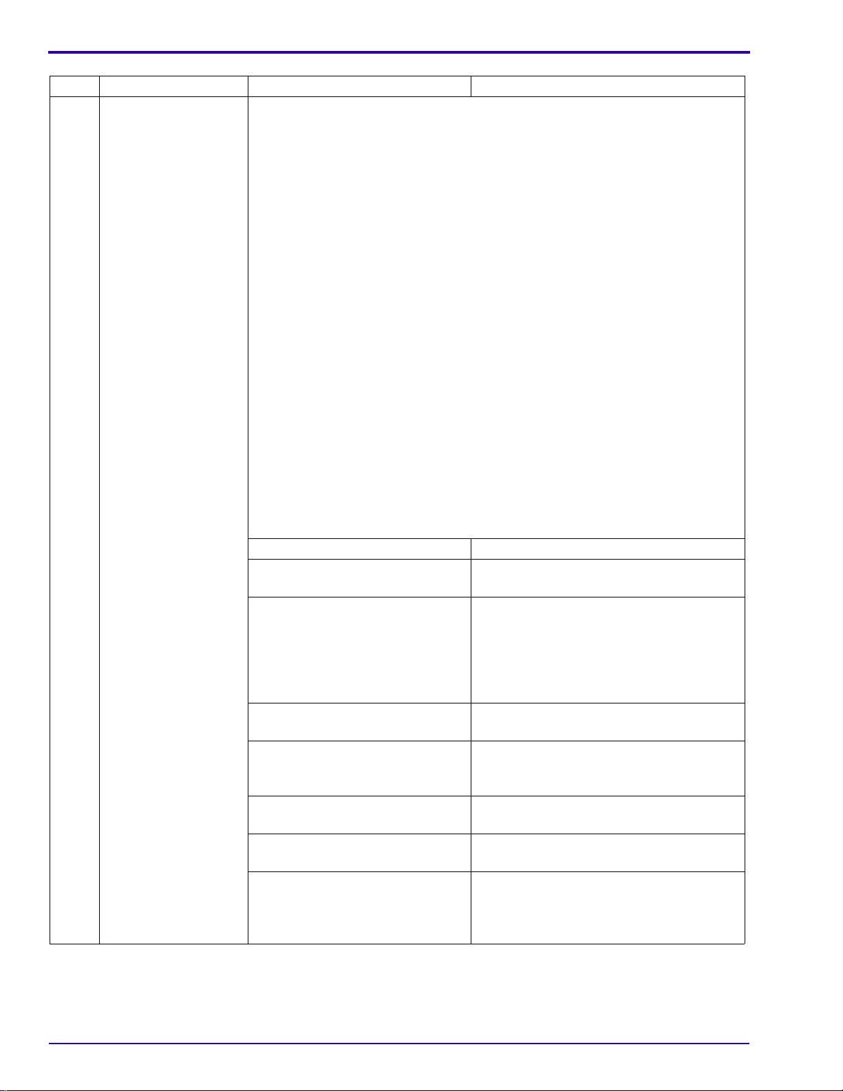
Fatal Errors
Code Description Possible Malfunction Action
E001 Microcontroller error 5000 BOARD Install a new BOARD.
E002 Dryer over maximum
temperature
Note
The maximum temperature
is 79°C (175°F).
Normally, the DRYER AC
OVERTEMPERATURE
THERMOSTAT opens
before the DRYER reaches
this temperature.
E003 Loss of film accumulator
data link
E004 Inoperative transport See E041.
E007 Developer thermistor
failure
E008 Fixer thermistor failure The FIXER HEATER is disabled when this error occurs.
E009 Dryer thermistor failure The DRYER HEATER is disabled when this error occurs.
E010 Analog-to-digital converter
failure
DRYER BLOWER When the DRYER HEATER energizes,
the DRYER BLOWER should energize.
Check:
• RELAY K1
• DRYER BLOWER
DRYER THERMISTOR Check that the resistance at 25°C (77°F)
is approximately 10 KW.
SOLID STATE RELAY U1 that
controls the DRYER HEATER
5000 BOARD Install a new BOARD.
No communication withthe 6000
BOARD
BOOT PROM U6018 on the
6000 BOARD
6000 BOARD Install a new BOARD.
5000 BOARD Install a new BOARD.
The DEVELOPER HEATER is disabled when this error occurs.
DEVELOPER THERMISTOR Install a new THERMISTOR.
FIXER THERMISTOR Install a new THERMISTOR.
DRYER THERMISTOR Install a new THERMISTOR.
All 3 HEATERS are disabled when this error occurs.
5000 BOARD Install a new BOARD.
Check U1.
De-energize and energize the
PROCESSOR to automatically reset the:
• MICROPROCESSOR on the 5000
BOARD
• MICROPROCESSOR on the 6000
BOARD
Install a new U6018.
4 January 1996 – 5B6342
Page 5
Error Codes
Code Description Possible Malfunction Action
E011 Developer heater failure This error occurs when the 8000 CURRENT SENSE BOARD detects no
current through the DEVELOPER HEATER.
When the temperature of the
developer solution is too high,
the DEVELOPER HEATER
Determine the cause for the high
developer temperature, and repair the
problem.
OVERTEMPERATURE
THERMOSTAT will open. The
THERMOSTAT will reset
automatically when the solution
cools.
No continuity for the
DEVELOPER HEATER
After the HEATER cools, check the
continuity. If necessary, install a new
HEATER.
The 5000 BOARD does not
energize the RELAY K5004 on
Check that the LED DS9 on the 5000
BOARD is energized.
the 5000 BOARD.
If necessary, install a new BOARD.
SOLID STATE RELAY U2 that
Check U2.
controls the DEVELOPER
HEATER
The 5000 BOARD does not
energize the SOLID STATE
Check that LED DS4 on the 5000
BOARD is energized.
RELAY U2.
If necessary, install a new BOARD.
8000 BOARD Install a new BOARD.
E012 Fixer heater failure This error occurs when the 8000 CURRENT SENSE BOARD detects no
current through the FIXER HEATER.
When the temperature of the
fixer solution is too high, the
Determine the cause for the high fixer
temperature, and repair the problem.
FIXER HEATER
OVERTEMPERATURE
THERMOSTAT will open. The
THERMOSTAT will reset
automatically when the solution
cools.
No continuity for the FIXER
HEATER
After the HEATER cools, check the
continuity. If necessary, install a new
HEATER.
SOLID STATE RELAY U5 that
Install a new U5.
controls the FIXER HEATER
The 5000 BOARD does not
energize the RELAY K5004 on
Check that the LED DS9 on the 5000
BOARD is energized.
the 5000 BOARD.
If necessary, install a new BOARD.
The 5000 BOARD does not
energize the SOLID STATE
Check that LED DS1 on the 5000
BOARD is energized.
RELAY U5.
If necessary, install a new BOARD.
8000 BOARD Install a new BOARD.
5B6342 – January 1996 5
Page 6

DIAGNOSTICS
Code Description Possible Malfunction Action
E013 Level sensor circuit failure This error occurs when the level sensor circuit on the 5000 BOARD
malfunctions. The following parts are disabled:
• DEVELOPER and FIXER REPLENISHMENT PUMPS
• RECIRCULATION PUMP
The temperature control for the fixer and developer is disabled.
5000 BOARD Install a new BOARD.
E014 Invalid program software E014 is displayed on the DEVELOPER TEMPERATURE DISPLAY. This
error disables all subsystems, except communications.
The main program software in
Download new software.
the EEPROM on the 5000
BOARD
E015 Invalid bootstrap software The bootstrap software for the
Install a new U5006.
PROM U5006 on the 5000
BOARD
E016 Invalid film accumulator
software
This error does not disable any subsystems. The PROCESSOR will remain
in the standby modeuntil the FILM DETECTOR SWITCHESactuate. These
SWITCHES provide information about the length of the film. Because the
6000 BOARD does not operate correctly, the PROCESSOR uses the
information from the SWITCHES to determine the replenishment rate.
The main program software in
Download new software.
the EEPROM on the 6000
BOARD
6 January 1996 – 5B6342
Page 7
Non-Fatal Errors
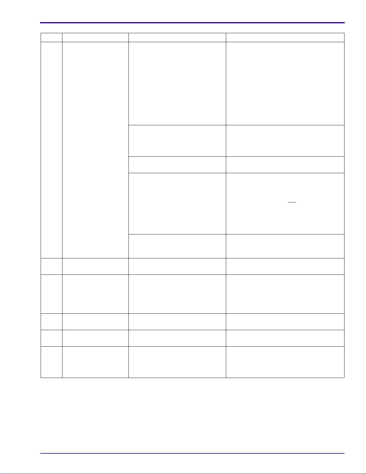
Code Description Possible Malfunction Action
E032 Developer tank fill
error
This error will occur if the:
• DEVELOPER TANK:
– does not fill in 2 minutes in normal operation
– does not fill in 10 minutes in the Tank Fill Mode
– is empty and the operator does not select the Tank Fill Mode
• REPLENISHER TANK is empty.
• REPLENISHMENT HOSE has:
– an obstruction
– a kink
– an air bubble
• TANKS of thePROCESSOR are filledwith water during the initial installation
.
The following parts will be disabled:
• DEVELOPER REPLENISHMENT PUMP
• RECIRCULATION PUMP
• temperature control for the fixer and developer
To prevent the error from occurring during the initial installation:
• Add 240 mL (8 fl oz) of developer to the DEVELOPER TANK before you fill
the PROCESSOR with water.
• Energize the RECIRCULATION PUMP to move the developer and remove
any air bubbles. Use the diagnostics to energize the PUMP.
LEVEL PROBES Clean and check the PROBES.
The solution level in the
REPLENISHER TANK is low.
Solution does not flow through the
HOSES between the
REPLENISHMENT TANK and the
REPLENISHMENT PUMP.
The DEVELOPER DRAIN VALVE
is opened.
SOLID STATE RELAY U3 that
controls the DEVELOPER
REPLENISHMENT PUMP
POPPET VALVES in the
DEVELOPER REPLENISHMENT
PUMP
DEVELOPER REPLENISHMENT
PUMP
The 5000 BOARD does not
energize the SOLID STATE
RELAY U3.
Mix new developer solution.
Check that the:
• HOSE CLAMPS are tight.
• HOSES:
– are round and opened
– have no obstructions or air bubbles
Close the VALVE.
Check U3.
Clean and check the VALVES.
Check the REPLENISHMENT PUMP
MOTOR B3.
Check that LED DS3 on the 5000 BOARD
is energized.
If necessary, install a new BOARD.
Error Codes
5B6342 – January 1996 7
Page 8
DIAGNOSTICS
Code Description Possible Malfunction Action
E033 Fixer tank fill error This error will occur if the:
• FIXER TANK
– does not fill in 2 minutes in normal operation
– does not fill in 10 minutes in the Tank Fill Mode
– is empty and the operator does not select the Tank Fill Mode
• REPLENISHMENT TANK is empty.
• REPLENISHMENT HOSE has:
– an obstruction
– a kink
– an air bubble
• TANKS of the PROCESSOR are filled with water during the initial installation
.
The following parts will be disabled:
• FIXER REPLENISHMENT PUMP
• RECIRCULATION PUMP
• temperature control for the fixer and developer
To prevent the error from occuring during the initial installation:
• Add 240 mL (8 fl oz) of fixer to the FIXER TANK before you fill the
PROCESSOR with water.
• Energize the RECIRCULATIONPUMP to movethe fixer andremove any air
bubbles. Use the diagnostics to energize the PUMP.
LEVEL PROBES Clean and check the PROBES.
The solution level in the
Mix new fixer solution.
REPLENISHER TANK is low.
Solution does not flow through the
HOSES between the
REPLENISHMENT TANK and the
Check that the:
• HOSE CLAMPS are tight.
• HOSES:
REPLENISHMENT PUMP.
– are round and opened
– have no obstructions or air bubbles
The FIXER DRAIN VALVE is
Close the VALVE.
opened.
SOLID STATE RELAY U4 that
Check U4.
controls the FIXER
REPLENISHMENT PUMP
POPPET VALVES in the FIXER
Clean and check the VALVES.
REPLENISHMENT PUMP
FIXER REPLENISHMENT PUMP Check the REPLENISHMENT PUMP
MOTOR B4.
The 5000 BOARD does not
energize the SOLID STATE
Check that LED DS2 on the 5000 BOARD
is energized.
RELAY U4.
If necessary, install a new BOARD.
8 January 1996 – 5B6342
Page 9
Code Description Possible Malfunction Action
E038 Loss of developer
cooling ability
Water does not enter the WASH
TANK.
Check:
• that water is supplied to the
PROCESSOR
– The water supply is turned on.
– The FILTER is clean.
• WASH WATER SOLENOID L1
– The operation is correct.
– The SCREEN has no obstructions.
• COOLING/DRAIN SOLENOID L2
The temperature of the water
entering the WASH TANK is too
hot.
Decrease the temperature of the water
supply. The wash water must be a
minimum of 5.5°C (10°F) below the setpoint
of the developer.
HEAT EXCHANGER in the
DEVELOPER TANK
The 5000 BOARD does not
energize the SOLENOID L1 or
Remove any obstructions from the
EXCHANGER.
Check for 24 V DC at TERMINALS1 and 2
on the WASH WATER SOLENOID L1.
de-energize the SOLENOID L2.
Check that 24 V DC is not present at
TERMINALS 1 and 2 for the
COOLING/DRAIN SOLENOID L2.
Error Codes
E040 Loss of dryer heating
ability
If necessary, install a new BOARD.
RECIRCULATION PUMP Check the RECIRCULATION PUMP
MOTOR B5. If necessary, install a new
PUMP.
A PANEL is not installed. Install the PANEL.
DRYER OVERTEMPERATURE
THERMOSTAT
Reset the THERMOSTAT. If the
THERMOSTATopensagain,determinethe
cause of the high temperature. If you
cannot determine the cause of theproblem,
install a new THERMOSTAT.
SOLID STATE RELAY U1 that
Check U1.
controls the DRYER HEATER
No continuity for the DRYER
HEATER
The 5000 BOARD does not
energize the SOLID STATE
Check that the resistance at 25°C (77°F) is
approximately 18 W.
Check that LED DS5 on the 5000 BOARD
is energized.
RELAY U1.
If necessary, install a new BOARD.
5B6342 – January 1996 9
Page 10
DIAGNOSTICS
Code Description Possible Malfunction Action
E041 Loss of transport speed control
When the PROCESSOR operates normally:
• The supply voltage from the +24 V POWER SUPPLY PS3 to the
PCOM and +24 V TERMINALS of the DRIVE MOTOR
Note
This error occurs when the
transport speed is adjusted for
10 seconds and the speed is
not within 7.6 cm/min (3 in./min)
of the setpoint.
CONTROLLER A4 is 24 V DC.
• The control voltage to TERMINALS 4 and 6 on the DRIVE MOTOR
CONTROLLER A4 is approximately:
– 0.85 V DC for the Extended Speed
– 1.55 V DC for the Standard Speed
– 2.25 V DC for the Rapid Speed
– 3.00 V DC for the K/RA Speed
• Feedback pulses from the DRIVE MOTOR CONTROLLER A4 at
Test Point MOTFB on the 5000 BOARD indicate the speed of the
DRIVE MOTOR.
If the transport operates slower than the set speed, the
MICROPROCESSOR increases the control voltage approximately
25 mV every second at TERMINALS 4 and 6 on the DRIVE MOTOR
CONTROLLER A4. If the voltage reaches 5 V DC, the
MICROPROCESSOR stops increasing the voltage. When you check
the voltage, if it is:
• 5 V DC, check for mechanical malfunctions.
• 0, check the wiring and the CONNECTOR.
5000 BOARD If the control voltage is not correct at
TERMINALS 4 and 6of the DRIVE MOTOR
CONTROLLER A4, install a new BOARD.
DC DRIVE MOTOR B6 or
DRIVE MOTOR
CONTROLLER A4
If B6 operates, but no pulses occur at Test
Point MOTFB on the 5000 BOARD or if the
supply voltage and the control voltagetothe
CONTROLLER are not correct, check:
• B6
•A4
E042 Loss of accessory data link Loose connections Check all connections between any
accessory and the PROCESSOR.
5000 BOARD Install a new BOARD.
2000 BOARD Install a new BOARD.
E045 Display data link error CABLES between the
Check the CABLES.
3000 and 5000 BOARD
10 January 1996 – 5B6342
Page 11
Warnings
Error Codes
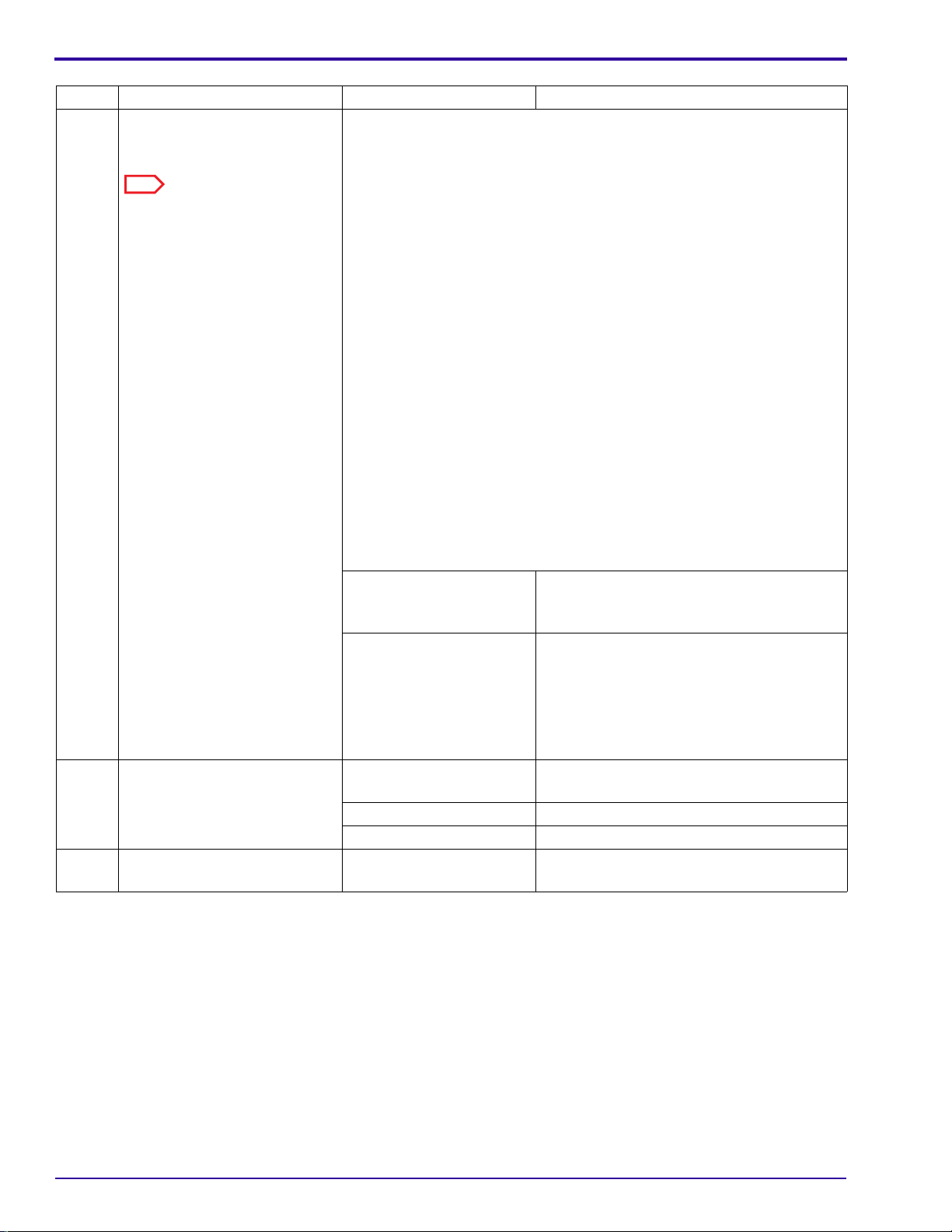
Error
Code
E128 Top cover not in
place
E129 Tanks currentlybeing
filled
E130 Replenish pumps
disabled
E132 Developer under set
temperature
E133 Developer over set
temperature
E134 Dryer under set
temperature
E137 Film accumulator
LED error
Error
Description
Possible
Malfunction Action
When this error occurs, the following functions are disabled:
• film transport
• film accumulation
The TOP COVER is opened. Close the TOP COVER.
INTERLOCKSWITCHESS3
and S4
• MAGNETS
7000 BOARD Install a new BOARD.
When this error occurs,
• the following functions are disabled:
– film transport
– film accumulation
• the following parts are disabled:
– RECIRCULATION PUMP
– 3 HEATERS
None None. This message will clear automatically.
None Use the KEYPAD to select either Automatic or
None None. This message will clear automatically when
None None. This message will clear automatically when
None None. This message will clear automatically when
6000 BOARD Check that no chemical deposits are on the
Check S3 and S4. If necessary, install a new
SWITCH or MAGNET.
Flooded Replenishment to enable the PUMPS.
the developer reaches the setpoint temperature.
the developer reaches the setpoint temperature.
the DRYER reaches the setpoint temperature.
PROTECTIVE COVER for the BOARD.
De-energize and energize the PROCESSOR to
reset the:
• MICROPROCESSOR on the 5000 BOARD
• MICROPROCESSOR on the 6000 BOARD
Check the BOARD. Use the internaldiagnostics. If
necessary, install a new BOARD.
E141 Low developer tank
level
E142 Low fixer tank level When this error occurs, the:
5B6342 – January 1996 11
When this error occurs, the:
• RECIRCULATION PUMP is disabled
• temperature control for the fixer and developer is disabled
None None. This error will clear automatically when the
developer solution reaches the correct level.
• RECIRCULATION PUMP is disabled
• temperature control for the fixer and developer is disabled
None None. This error will clear automatically when the
fixer solution reaches the correct level.
Page 12

DIAGNOSTICS
12 January 1996 – 5B6342
Page 13

Section 2: Mechanical Diagnostics
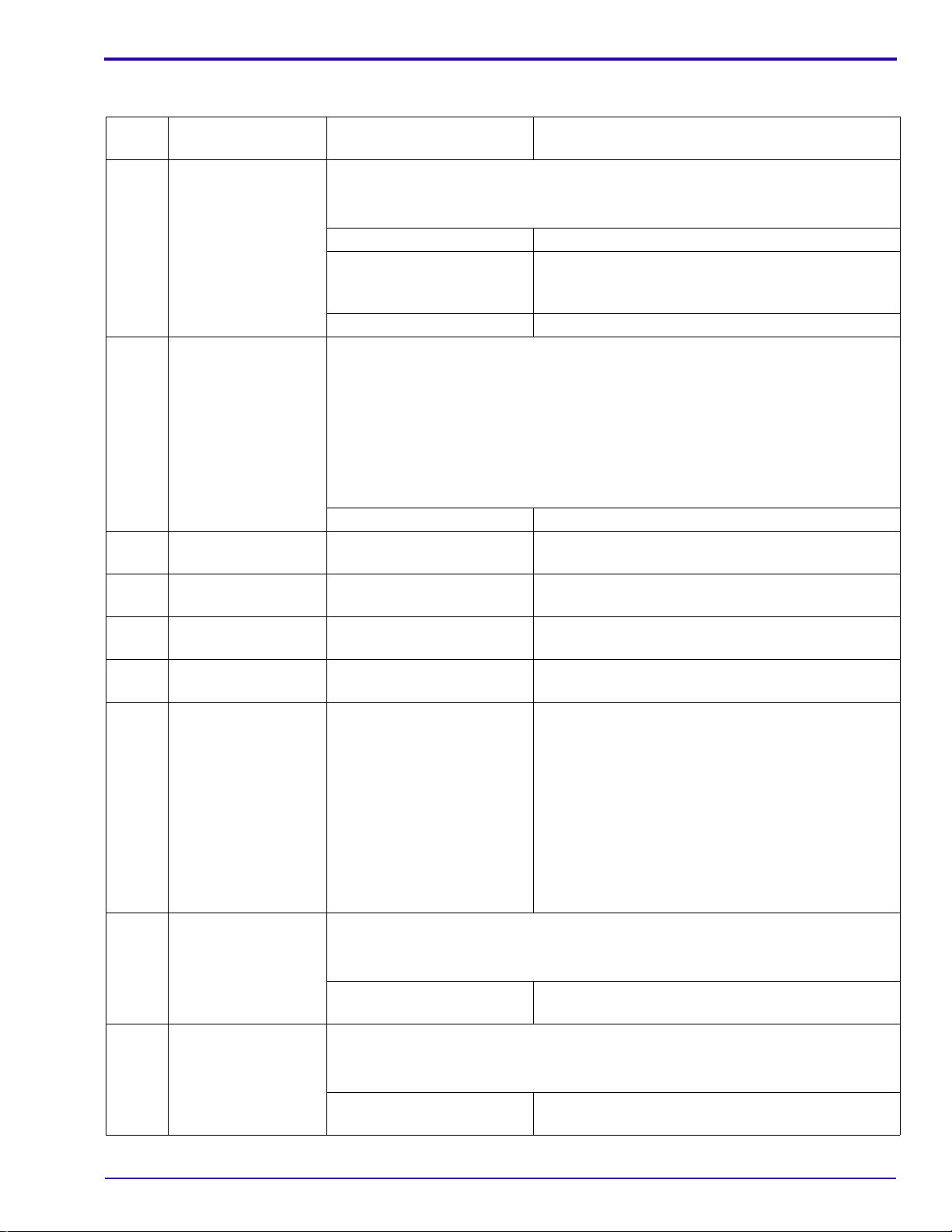
Transport Malfunction
Possible Cause Check
RACK and CROSSOVER
ASSEMBLIES
ROLLER ASSEMBLIES ROLLERS
DRYER AIR TUBE BAFFLES
TOP COVER TOP COVER
RACK and CROSSOVER ASSEMBLIES:
correct positions
seated correctly
• squareness
– SeetheAdjustments and Replacements,PublicationNo.5B6340,
RACKS and CROSSOVERS.
Adjusting the Squareness of the CROSSOVERS
Adjusting the Squareness of the RACKS
• cleaned completely
– See the Preventive Maintenance, Publication No. 5B6747.
CROSSOVER TROUGHS
• correct positions
• correct positions
• rotate freely
• GUDGEONS
– no damage
– If necessary, install new ROLLERS.
GEARS, SPROCKETS, and IDLERS
• engage correctly
• not broken or worn
BEARINGS
• no wear
SPRINGS and E-RINGS
• not broken or missing
RACK ASSEMBLY
• DRIVE CHAIN
– tension
• installed
Temperature setting of the DRYER
lowest possible setting to provide the best image quality
•
DRYER ROLLERS and AIR TUBES
• seated correctly
DRYER BELT
• moves correctly
• closed
Mechanical Diagnostics
5B6342 – January 1996 13
Page 14

DIAGNOSTICS
Artifacts and Wrong Film Densities
Possible Cause Check
Replenishment system Replenishment rates
• correct setting
HOSES
• opened and round
• no obstructions or air bubbles
HOSE CLAMPS
• tight
REPLENISHMENT PUMP
• operation
• calibration
Replenishment chemicals
• Change any chemicals that are:
– not mixed correctly
– exhausted
– contaminated
Note
When you mix chemicals:
• Mix a maximum of a 2-week supply of the DEVELOPER
RELENISHER.
• Follow all directions for mixing chemicals and solutions.
• Use a SPLASH GUARD and DRIP TRAY when you remove the
FIXER RACK from thePROCESSOR to prevent contamination ofthe
developer.
DEVELOPER and FIXER TANKS
• DRAIN VALVES
– completely closed
Recirculation system DEVELOPER and RECIRCULATION HOSES
• ORIFICES
– no obstructions
DEVELOPER FILTER
• If necessary, install a new FILTER.
Movement of the solutions at the surface of the PROCESSOR TANKS
when you enrgize the PROCESSOR and the TANKS are full.
• If the solutions do not move, check that the:
– HOSES have no obstructions or air bubbles in the recirculation
system
– RECIRCULATION PUMP operates
– DEVELOPER FILTER is clean and in the correct position
14 January 1996 – 5B6342
Page 15

Possible Cause Check
RACK and CROSSOVER
ASSEMBLIES
RACKS and CROSSOVERS
• correct position
• seated correctly
• cleaned completely
– See the Preventive Maintenance, Publication No. 5B6747.
CROSSOVER TROUGHS and EVAPORATION COVERS
• correct position
• TROUGHS
– clean
• TROUGH DRAINS
– no obstructions
• CROSSOVER YOKE
– correct position
ROLLERS ROLLERS
• clean and not scratched
• correct position
• rotate freely
• GUDGEONS
– no damage
– If necessary, install new ROLLERS.
DETECTOR ROLLERS
• clean
GEARS, SPROCKETS, and IDLERS
• engage correctly
• no wear
BEARINGS
• no wear
SPRINGS
• not broken or missing
DEVELOPER and FIXER RACK ASSEMBLIES
• ROLLER SPROCKETS
– engage correctly
• DRIVE CHAINS
– correct adjustment of the tension
Mechanical Diagnostics
5B6342 – January 1996 15
Page 16

DIAGNOSTICS
Possible Cause Check
Drying system DRYER AIR TUBES
• clean
– If necessary, use a BOTTLE BRUSH and water to clean the
TUBES and SLOTS in the TUBES.
• BAFFLES
– installed
Temperature setting of the DRYER
• lowest possible setting to provide the best image quality
• exhaust for the PROCESSOR
– meets the specifications
– See the Site Specifications, Publication No. 5B6338.
Wrong water temperature Temperature of the water
• 4.5 - 29.5˚C (40 - 85˚F)
Wash water WASH TANK and CROSSOVER TROUGH
• Water flows into these parts
COVERS and PANELS TOP COVER
• closed
ACCESS PANEL
• installed
EVAPORATION COVERS
correct position
•
Ventilation system Exhaust for the PROCESSOR
• meets the specifications
• See the Site Specifications, Publication No. 5B6338.
• Internal EXHAUST FAN operates correctly
External EXHAUST HOSE
• connected from the AIR EXHAUST on the PROCESSOR to the
BUILDING EXHAUST
Internal EXHAUST HOSE
• connected from the internal EXHAUST FAN to the AIR EXHAUST
16 January 1996 – 5B6342
Page 17

Wet Films
Possible Cause Check
Film and chemicals are not
compatible.
Replenishment system Replenishment rates
Film
• compatible with the selected cycle
• correct setting
HOSES
• opened and round
• no obstructions or air bubbles
HOSE CLAMPS
• tight
REPLENISHMENT PUMP
• operation
• calibration
Replenishment chemicals
• Change any chemicals that are:
– not mixed correctly
– exhausted
– contaminated
Mechanical Diagnostics
Note
When you mix chemicals:
• Mix a maximum of a 2-week supply of the DEVELOPER RELENISHER.
• Follow all directions for mixing chemicals and solutions.
• Use a SPLASH GUARD and DRIP TRAY when you remove the FIXER
RACK from the PROCESSOR to prevent contamination of the developer.
REPLENISHMENT TANKS
• quantity of solution
DEVELOPER and FIXER TANKS
• DRAIN VALVES
– completely closed
Recirculation system Movement of the solutions at the surface of the PROCESSOR TANKS when
you energize the PROCESSOR and the TANKS are full.
• If the solutions do not move, check that the:
– HOSES have no obstructions or air bubbles in the recirculation system
– RECIRCULATION PUMP operates
– DEVELOPER FILTER is clean and in the correct position
5B6342 – January 1996 17
Page 18

DIAGNOSTICS
Possible Cause Check
Drying system DRYER AIR TUBES
• clean
– Ifnecessary,useaBOTTLEBRUSHandwatertocleantheTUBESand
SLOTS in the TUBES.
• BAFFLES
– installed
DRYER
• lowest possible temperature to provide the best image quality
DRYER AIR EXHAUST
• no obstructions
• installed correctly
– If necessary, see the Installation Instructions, Publication No. 5B6339.
DRYER HEATER
• operates correctly
DRYER ROLLERS and AIR TUBES
• seated correctly
Wash water Water
• input to the WASH TANK
• temperature
• input to the CROSSOVER TROUGHS
– is connected
RACK and CROSSOVER
ASSEMBLIES
WASH RACK
• SQUEEGEE ROLLERS
– clean
– good condition
SPRINGS
• not broken or missing
SQUEEGEE ASSEMBLY
• operates correctly
• ROLLERS
– clean
– good condition
• SPRINGS
– correct tension
YOKE and CROSSOVER TROUGHS
• installed correctly
CROSSOVER TROUGHS
holes are
• opened
– Ifnecessary,cleantheholes to prevent an overflowofthewaterfromthe
TROUGHS into the DEVELOPER and FIXER TANKS.
18 January 1996 – 5B6342
Page 19

Solution Levels
Possible Cause Check
Replenishment system Replenishment rates
• correct setting
HOSES
• opened and round
• no obstructions or air bubbles
REPLENISHMENT PUMP
• operation
• calibration
REPLENISHMENT TANKS
• quantity of solution
POPPET VALVES
• clean
• no damage
DEVELOPER and FIXER TANKS
• DRAIN VALVES
– no leakage
CROSSOVER TROUGHS
• correct positions
• TROUGHS
– clean
• TROUGH DRAINS
– no obstructions
Mechanical Diagnostics
5B6342 – January 1996 19
Page 20

DIAGNOSTICS
20 January 1996 – 5B6342
Page 21

Section 3: Internal Diagnostics
Accessing the Internal Diagnostics
Procedure
Internal Diagnostics
READY
DRYER
TEMP
1 2 3 4 CANCEL
∧∨CYCLE MORE DONE/
INFO SETUP OPTIONS DONE/
USAGE DIAG SW
SLEEP SELECT
CYCLE
VERSION
MORE GO TO
SETUP
REQUEST
RETURN
RETURN
MORE DONE/
RETURN
[1] Press “GO TO SETUP” from the main menu.
[2] Enter the access code. If the customer:
• has not changed the code, it is 4213.
• has changed the code, see the Adjustments
and Replacements, Publication No. 5B6340,
Electrical, Resetting or Bypassing the Access
Code.
[3] Press “MORE”.
[4] Press “INFO”.
[5] Press “DIAG”todisplaythefirstdiagnosticmenu.
Advance to the next page to see the
3 diagnostic menus.
In addition to accessing the first diagnostic menu
from this screen, you can access additional
screens that will enable you to access more
information about the PROCESSOR. Select:
• “USAGE” to access information about the
type and quantity of film and chemicals used
in the PROCESSOR
• “SW VERSION” to access the software
version number for the following programs for
the 5000 and 6000 BOARDS:
– Boot program
– Main program
• “MORE” to access the total number of hours
the:
– PROCESSOR has been energized
– DRIVE MOTOR has been energized
• “DONE/RETURN” repeatedly to return to the
main menu
5B6342 – January 1996 21
Page 22

DIAGNOSTICS
D1 Menu
[6] Press “MORE” to display the D2 Menu.
VIEW
ERRORS
D2 Menu
HEATER
TESTS
D3 Menu
PUMP
TESTS
FILM
DETECT
SOLENOID
TESTS
RECEPT
OUTLET
SENSOR
TESTS
MOTOR
TESTS
FILM
ACCUMUL
MORE DONE/
RETURN
[7] Press “MORE” to display the D3 Menu.
MORE DONE/
RETURN
[8] Press “MORE” to return to the first diagnostic
menu.
MORE DONE/
RETURN
22 January 1996 – 5B6342
Page 23

Diagnostic Menus
Overview
When you enter the diagnostic menu, the software:
• de-energizes the following electrical components:
– all HEATERS
– all PUMPS
– all SOLENOIDS
– the BLOWER and DRIVE MOTORS
• de-energizes the SAFELIGHT OUTLET
• disables the error code detection
You can use the internal diagnostics to energize and de-energize electrical components. When you
energize a component, it will automatically de-energize in 4 minutes.
Details
To view the specific options that are availablefrom the D1, D2, and D3 Menus, see the Flowcharts for
the Internal Diagnostics on the following pages.
Menus
Internal Diagnostics
D1 Menu
VIEW
ERRORS
D2 Menu
HEATER
TESTS
FILM
DETECT
SOLENOID
TESTS
SENSOR
TESTS
MOTOR
TESTS
MORE DONE/
RETURN
MORE DONE/
RETURN
From the first menu, you can:
• access History and Frequency Error Logs
• monitor FILM DETECTOR SWITCHES
• monitor SENSORS
• access the D2 Menu
• return to the main menu
From this menu, you can:
• energize and de-energize:
– HEATERS
– SOLENOIDS
– MOTORS
• access the D3 Menu
• return to the main menu
Note
When you energize the HEATERS, energize the
RECIRCULATION PUMPS, too, to prevent the
OVERTEMPERATURE THERMOSTAT from opening.
5B6342 – January 1996 23
Page 24

DIAGNOSTICS
D3 Menu
PUMP
TESTS
RECEPT
OUTLET
FILM
ACCUMUL
MORE DONE/
RETURN
From this menu, you can:
• energize and de-energize:
– PUMPS
– RECEPTACLE OUTLET
– LEDs
• calibrate LEDs on the 6000 BOARD
• determine film size
• access the D1 Menu
• return to the main menu
24 January 1996 – 5B6342
Page 25

Flowcharts for the Internal Diagnostics
Internal Diagnostics
From DIAG
DONE /
RETURN
MORE
TESTS
SENSOR
To D2 Menu
DONE /
RETURNTANK
MORE
COVER
FIXERDEV
TANK
DEVELOPER TANK : NOT FULL
DONE /
OFF
DRIVE
ROOM LIGHT : LIGHT DETECTED
DONE /
RETURN
MORE
TEMP
FIXER
DEV
TEMP
LIGHT
ROOM
DONE /
RETURN
TYPE
CLEAR
DONE /
RETURN
MORE
TEMP
DRYER
PRESS BUTTON TO SELECT
CANCEL
REQUEST
ALL
D1 Menu
H148_9013EC
FILM
DETECT
VIEW
PRESS BUTTON TO SELECT
ERRORS
ON RETURNDRIVE
DRIVE
NONDRIVE
SIDE
DRIVE SIDE : FILM DETECTED
DONE /
RETURN
LOG
FREQ
LOG
PRESS BUTTON TO SELECT
HISTORY
E129 : 1 3/28/95 10:06:04 AM
1) E002 09/21/94 18:09
2) E014 05/23/94 22:35
CLEAR
ENTRY
V
V V
DONE /
RETURN
V
FATAL
NON
FATAL
SELECT TYPE OF ERROR TO BE CLEARED
WARNING
5B6342 – January 1996 25
Page 26

DIAGNOSTICS
From D1 Menu
DONE /
RETURN
MORE
TESTS
MOTOR
To D3 Menu
DONE /
RETURNBLOWER
BLOWER
EXHAUST
DRYERDRIVE
PRESS BUTTON TO SELECT
MOTOR
DONE /
RETURNSOLENOID
DRYER BLOWER : ON
DONE /
RETURN
OFF
ON
DONE /
RETURN
DONE /
RETURN
SPEED
SELECT
OFF
ON
DRIVE MOTOR : ON
DONE /
RETURN
CANCELDEFAULT
REQUEST
SETTING
V
V
48 IN/MIN = DRIVE MOTOR SPEED
H148_9015EC
TESTS
SOLENOID
TESTS
PRESS BUTTON TO SELECT
D2 Menu
HEATER
DRAINWASH
PRESS BUTTON TO SELECT
WATER
DONE /
RETURN
DRYER
HEATER
FIXER
HEATER
DEV
PRESS BUTTON TO SELECT
HEATER
DRAIN SOLENOID : ON
DEVELOPER HEATER : ON
OFF
ON
DONE /
RETURN
OFF
26 January 1996 – 5B6342
Page 27

Internal Diagnostics
From D2 Menu
DONE /
RETURN
MORE
FILM
ACCUMUL
To D1 Menu
DONE /
RETURN
CALIB
DET
LED/ LED/
PRESS BUTTON TO SELECT
DONE /
RETURN
DONE /
RETURN
DONE /
RETURN
OUTLET
RECEPT
PUMP
TESTS
PRESS BUTTON TO SELECT
D3 Menu
ON OFF
RECEPTACLE OUTLET : OFF
RETURN
PUMP
RECIRC
FIXER DONE /
REPLEN
DEV
PRESS BUTTON TO SELECT
REPLEN
1 ++++?++++++ ++----?----22 OPERATION COMPLETE
RECIRCULATION PUMP : OFF
+ Film is detected.
DONE /
RETURN
ON OFF
- Film is not detected.
? LED does not operate correctly.
DONE /
RETURN
ON OFF
FIXER REPLENISH PUMP : OFF
DONE /
RETURN
ON OFF
DEV REPLENISH PUMP : OFF
H148_9014EC
5B6342 – January 1996 27
Page 28

DIAGNOSTICS
28 January 1996 – 5B6342
Page 29

Section 4: Reports
Overview
Options
The equipment software enables you to use a PRINTER to obtain copies of the following reports.
• A Status Report, which includes information about:
– Processing Parameters
– Options
– Automatic Starting and Stopping Times
– Software Versions
– Miscellaneous Information
• A Usage Report, which includes information about the use of:
– Film
– Chemicals
• A Log Report, which provides information about errors in 2 formats:
– Frequency
– History
Reports
Requirements
You must have the following components to print reports:
• CABLES
• PRINTER with the following specifications:
The
– PRINTER ADAPTER CABLE TL-5004
– INTERFACE CABLE TL-4391
– 9600 baud
– 8 data bits
– no parity
– serial interface
– XON/XOFF protocol
Kodak Diconix
180si PRINTER meets these specifications.
5B6342 – January 1996 29
Page 30

DIAGNOSTICS
Printing Reports
Procedure
[1] Connect:
• the INTERFACE CABLE TL-4391 to the PROCESSOR INTERFACE CONNECTOR (PIC) on either the
DRYER END or the FEED END of the PROCESSOR
• the PRINTER ADAPTER CABLE TL-5004 to the INTERFACE CABLE TL-4391 and the PRINTER
PROCESSOR
INTERFACE
CONNECTOR
(PIC)
H148_0174BCB
H148_0174BA
READY
DRYER
TEMP
SLEEP SELECT
CYCLE
MORE GO TO
SETUP
1 2 3 4 CANCEL
REQUEST
∧∨CYCLE MORE DONE/
RETURN
INFO SETUP OPTIONS DONE/
RETURN
USAGE DIAG SW
VERSION
PROC
PRINTER MORE DONE/
HOURS
MORE DONE/
RETURN
RETURN
FEED ENDDRYER END
[2] Press “GO TO SETUP” from the main menu.
[3] Enter the access code.
[4] Press “MORE”.
[5] Press “INFO”.
[6] Press “MORE” to access the options for the
printer.
[7] Press “PRINTER” to access the options for the
printer.
30 January 1996 – 5B6342
Page 31

Reports
SELECT
PRINTER
PRINT TO
PIC
SELECT
PRINTER
PRINT
STATUS
PRINT
REPORT
PRINT TO
EBOX
PRINT
REPORT
PRINT
USAGE
PRINT
ALL
PRINT
ALL
PRINT
LOGS
DONE/
RETURN
DONE/
RETURN
DONE/
RETURN
DONE/
RETURN
[8] From this screen, you can:
• Press “SELECT PRINTER” to indicate which
connection you used in Step 1:
– PROCESSOR INTERFACE
CONNECTOR (PIC)
– ELECTRICAL BOX (EBOX)
• Press “PRINT REPORT” to select which
reports you want to print:
– Status
– Usage
– Log
• Press “PRINT ALL” to print all the reports at
once.
• Press “DONE/RETURN” repeatedly to return
to the main menu.
5B6342 – January 1996 31
Page 32

DIAGNOSTICS
32 January 1996 – 5B6342
Page 33

Section 5: Appendix
SOLID STATE RELAYS (SSR)
Possible Malfunctions
3 possible malfunctions can occur:
• The control voltage is supplied, but the LOAD does not operate.
– Result: The LOAD malfunctions.
• The control voltage is supplied, but the SSR does not conduct the voltage.
– Result: The SSR malfunctions.
• The 5000 BOARD does not receive the supply voltage at the correct time.
– Result: The 5000 BOARD malfunctions.
Use the following procedures to determine which component malfunctions.
L1
Connect this wire to energize the load.
L2
LOAD*
Appendix
*for example, a
MOTOR or HEATER
21
+3
4
Apply +5 V DC here
to energize the
SOLID STATE RELAY (SSR)
H148_0001BC_
Checking the LOAD
Warning
Dangerous Voltage
[1] De-energize the PROCESSOR.
[2] Place a CLIP between TERMINALS 1 and 2 on the SSR.
[3] Energize the PROCESSOR
[4] If the LOAD:
• operates, the LOAD is not the problem.
• does not operate, install a new LOAD.
[5] De-energize the PROCESSOR.
[6] Remove the CLIP.
5000 BOARD
5B6342 – January 1996 33
Page 34

DIAGNOSTICS
Checking the SSR and the 5000 BOARD
Warning
Dangerous Voltage
[1] De-energize the PROCESSOR.
[2] Disconnect the wire that connects the 5000 BOARD to TERMINAL 3 on the SSR.
[3] Place a CLIP between:
• +5 V DC on the QUAD POWER SUPPLY
• TERMINAL 3 on the SSR
[4] Energize the PROCESSOR.
[5] If the LOAD:
• operates, install a new 5000 BOARD.
• does not operate, install a new SSR.
[6] De-energize the PROCESSOR.
[7] Remove the CLIP.
34 January 1996 – 5B6342
Page 35

Publication History
Section 6: Publication History
Print Date Pub. No. ECO No. Affected Pages File Name Notes
October 1995 5B6342 2649-029 All dg3425_1_029.doc First printing.
January 1996 5B6342 2649-062 Covers dg3425_1_062.doc Graphic Unification.
January 1998 5B6342 2649-062 All dg342500.fm First CD-ROM printing. Content
is identical to January 1996
version; formatting may vary from
print version.
5B6342 – January 1996 35
Page 36

Kodak, Diconix,
and
X-Omat
are trademarks.
dg342500.fm
Printed In USA
HEALTH IMAGING
EASTMAN KODAK COMPANY ● ROCHESTER, N.Y. 14650
 Loading...