

Page 1
ROUGH DRAFT
THEORY GUIDE
for the
Publication No. Preliminary
10/8/90
Kodak X-Omat
M6RA PROCESSOR
H108_0003DA
Page 2

PLEASE NOTE
The information contained herein is based on the experience and knowledge relating to the subject matter gained by
Eastman Kodak Company prior to publication.
No patent license is granted by this information.
Eastman Kodak Company reserves the right to change this information without notice, and makes no warranty, express
or implied, with respect to this information. Kodak shall not be liable for any loss or damage, including consequential or
special damages, resulting from the use of this information, even if loss or damage is caused by Kodak’s negligence or
other fault.
This equipment includes parts and assemblies sensitive to damage from electrostatic discharge. Use
caution to prevent damage during all service procedures.
Table of Contents
Description Page
2 Preliminary
Page 3
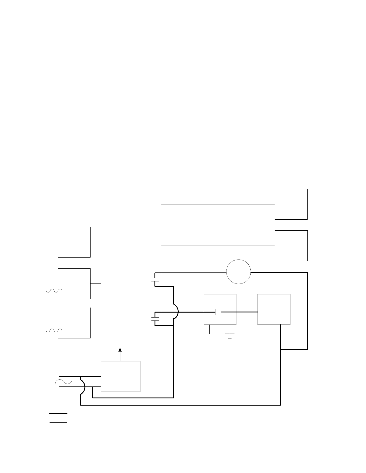
Developer Temperature Control R3, has an internal overtemperature THERMOSTAT.
If recirculation is lost, the internal THERMOSTAT in
When the GPMC (500 Board) senses that both the
DEVELOPER and FIXER PROBES are submerged
in solution (reduced resistance), RELAY K503 is
energized, thus applying line AC voltage across B5,
the RECIRCULATION PUMP. Both the DEVELOPER
LEVEL PROBE and the DEVELOPER
THERMISTOR, R3, are looked at by the 500 Board.
K504 is used as an enable for the DEVELOPER
HEATER. K503 turns on the RECIRCULATION
PUMP. Due to the changes in resistance of R3,
SSRU2 is turned on and off at varying rates to
R3 will open. The 500 Board also controls the
WASH WATER SOLENOID, L1, and the
DEVELOPER COOLING SOLENOID, L2. In the
event that developer temperature goes .5°F above
set temperature, it opens the DEVELOPER
COOLING SOLENOID which is in the DRAIN of the
WASH TANK. It also turns on WASH WATER
SOLENOID, L1. The rate of L1 is 1.5 gallons per
minute; the rate of L2 is 1.2 gallons per minute; and
the DRAIN is routed through the cooling loop at the
bottom of the DEVELOPER TANK.
control the temperature. The DEVELOPER HEATER,
BLOCK DIAGRAM
DEVELOPER TEMPERATURE CONTROL
R6
DEVELOPER
THERMISTER
DEV.
LEVEL
PROBE
FIXER
LEVEL
PROBE
500
BOARD
MICROPROCESSOR
K503
(DS3)
K504
(DS4)
CONTROL
L2 L1
SSR
U2
RECIRC
PUMP
B5
WASH
WATER
SOLENOID
L1
COOLING
DUMP
SOLENOID
L2
DEVELOPER
HEATER
HR-3
L1
L1
L2
AC
DC
QUAD
POWER
SUPPLY
H108_9003DC
Preliminary 3
Page 4
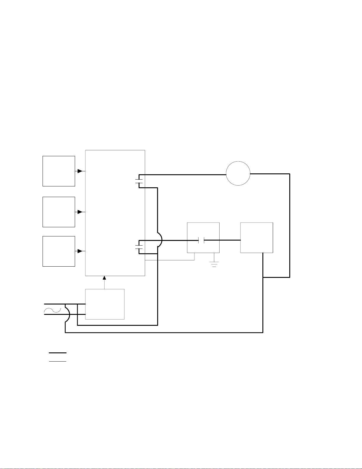
Fixer Temperature Control thermistor is R4. The 500 Board senses the
variations in resistance. K503 is the enable. The
Resistance, or R4, is sensed by the GPMC (500
Board) and is used to control SSRU2. K504 enables
the DEVELOPER HEATER. SSRU2 controls the
DEVELOPER HEATER. K503 turns on the
RECIRCULATING PUMP, B5. So we have a very
large swing — plus 15°F, minus 10°F — and is
variations are used to control SOLID STATE RELAY
U5. The FIXER HEATER is R4. FIXER HEATER
R4 has an internal overtemperature THERMOSTAT
that in the event of loss of recirculation, it will open.
The 500 Board also turns on K503 which turns on
the RECIRCULATION PUMP, B5.
normally controlled at 90°for all cycles. The
BLOCK DIAGRAM
FIXER TEMPERATURE CONTROL
500
R-4
FIXER
THERMISTER
BOARD
MICROPROCESSOR
K503
(DS3)
L2 L1
RECIRC
PUMP
B5
L1
L2
FIXER
LEVEL
PROBE
DEV.
LEVEL
PROBE
AC
DC
QUAD
POWER
SUPPLY
K504
(DS4)
L2
CONTROL
FIXER
SSR
U5
FIXER
HEATER
R-4
L1
H108_9004DC
4 Preliminary
Page 5

Dryer Temperature Control HEATER SOLID STATE RELAY, U1. The DRYER
OVERTEMPERATURE THERMOSTAT should
The DRYER THERMISTOR is R5. Variations in
resistance of R5 are sensed by the 500 Board
(GPMC). This controls the DRYER HEATER
normally be closed unless the HEATERS are turned
on with no air movement. K502 which is on the 500
Board turns on the DRYER BLOWER MOTOR.
RELAY, an enable which is K501; The DRYER
BLOCK DIAGRAM
DRYER TEMPERATURE CONTROL
500 BOARD
L1
L2
DRYER
THERMIS-
TOR
R5
L1
L2
K501
(DS1)
K502
(DS2)
QUAD
POWER
SUPPLY
SSR U1
CONTROL
DRYER
O.T.
THERMOSTAT
S7
RELAY K8
DRYER
HEATER
R1 + R2
DRYER
BLOWER
MOTOR
B1
AC
DC
H108_9005DC
Preliminary 5
Page 6

Developer/Fixer Replenishment Control equivalent of a 14 x 17 sheet of film, it tells the
DEVELOPER SOLID STATE RELAY, U3, and the
The COVER INTERLOCK SWITCH, F6, must be
closed. The UFD (300 Board) senses film is going
through. DETECTOR SWITCHES S1 and S2 detect
the end of the film. The timing takes place on the
300 Board and the 500 Board decides when the
alarm within the UFD (5500 5600 Board) will sound
off to let the operator know when the next film can
FIXER SOLID STATE RELAY, U4, to turn on the
DEVELOPER REPLENISHMENT PUMP, B3, and the
FIXER REPLENISHMENT PUMP, B4, for times that
are set up in the software. To check replenishment
rates there is a replenishment calibrate switch, S5,
and it feeds directly through the 500 Board to both
PUMPS.
be fed into the PROCESSOR. When the UFD (300)
Board signals the 500 Board that it has detected the
BLOCK DIAGRAM
DEVELOPER/FIXER REPLENISHMENT CONTROL
COVER
INTERLOCK
S6
DRIVESIDE
FILM DET.
NON-DRIVE
SIDE FILM
DET.
REPLENISH
CALIBRATE
SWITCH
300
BOARD
S1
OR
S2
S5
5600
BOARD
FILM
ACCUMULATOR
L1
L2
AC
DC
500
BOARD
MICRO-
PROCESSOR
POWER
SUPPLY
DC
A1
CONTROL
L2
CONTROL
L2
L1
DEVELOPER
SSR-U3
FIXER
SSR-U4
DEV-
REPLENISH
PUMP
B3
FIXER
REPLENISH
PUMP
B4
H108_9006DC
6 Preliminary
Page 7

D.C. Drive Motor Control BOARD 400, and through RELAY K506. The control
is a varying DC voltage that goes to A2 from the 500
INTERLOCK SWITCH F6 must be closed.
Instructions are given to the 500 Board via the 200
Board (Interface Board) KEYPAD display to tell the
500 Board in which cycle to operate. This
information is passed to the DRIVE MOTOR SPEED
Board. The DRIVE MOTOR SPEED CONTROLLER
uses this as a control voltage and provides power to
the D.C. DRIVE MOTOR. The D.C. DRIVE MOTOR
produces feedback pulses which are fed back to the
500 Board.
CONTROLLER, A2, through the CURRENT LIMITER
BLOCK DIAGRAM
D.C. DRIVE MOTOR CONTROL
COVER
INTERLOCK
SW S4
L1
L2
PCB 200
INTERFACE
5600
BOARD
FILM
ACCUMULATOR
AC
DC
500
BOARD
MICRO-
PROCESSOR
POWER
SUPPLY
DC
A1
24 V dc
FUSE
F2
DRIVE
MOTOR
SPEED
CONTROLLER
A2
DC
DRIVE
MOTOR
B6
H108_9007DC
Preliminary 7
Page 8

p108_9008ec
Figure 1 All Systems Block Diagram
8 Preliminary
Page 9

BLANK PAGE
Preliminary 9
Page 10

3056tg_a.txt
EASTMAN KODAK COMPANY • ROCHESTER, N.Y. 14650Printed in USA
Kodak
and
X-Omat
are trademarks.
Health Sciences Division
Page 11

Datalogics, Inc. PAGER Typesetting System
Job Completion Statistics
There were 3 errors in this job. Please check your .LOG file to resolve errors. If you encounter
problems that you can’t resolve yourself, please contact your support staff as soon as possible. Keep
this sheet along with the rest of the output so that we can determine the cause of this problem.
Thank you.
CAPS Support
Filename:
Composition Procedure: PRINT
Output Device: POSTSCRIPT V6.008
User: HSD_JUNK
Date: 4-JUN-98
Time: 19:25
Total Pages: 10
Processing Info Used: None!
_$1$DIA3:[HSD.COMMON.TRAD.3056.MKTG]3056TG_A.TXT;14
 Loading...