

Page 1

Publication No. 5B6328
OPERATOR MANUAL
for the
Kodak X-Omat 3000 RA Processor
30SEP98
Supersedes 5B6328
NOV95
H150_0035DA
HEALTH IMAGING
© Eastman Kodak Company
Page 2

PLEASE NOTE The information contained herein is based on the experience and knowledge relating to the
subject matter gained by Eastman Kodak Company prior to publication.
No patent license is granted by this information.
Eastman Kodak Company reserves the right to change this information without notice, and
makes no warranty, express or implied, with respect to this information. Kodak shall not be
liable for any loss or damage, including consequential or special damages, resulting from any
use of this information, even if loss or damage is caused by Kodak’s negligence or other fault.
Warning
To avoid hazardous conditions, keep floors and floor coverings around your Kodak X-Omat Processor and associated
drains clean and dry at all times. Any accumulation of fluids from mixing tanks, drain lines, etc, should be cleaned
up immediately. In the event of an accumulation of liquid due to backup, overflow, or other malfunctions of the drain
associated with your Kodak X-Omat Processor, call a plumber or other contractor to correct any problem with the
drain. Kodak accepts no responsibility or liability whatsoever for the serviceability of any drain connected to or
associated with a Kodak X-Omat Processor. Such drains are the sole responsibility of the customer.
Table of Contents
Description Page
Introduction. . . . . . . . . . . . . . . . . . . . . . . . . . . . . . . . . . . . . . . . . . . . . . . . . . . . . . . . . . . . 4
Intended Audience . . . . . . . . . . . . . . . . . . . . . . . . . . . . . . . . . . . . . . . . . . . . . . . 4
How To Use this Manual . . . . . . . . . . . . . . . . . . . . . . . . . . . . . . . . . . . . . . . . . . 4
Symbol Key. . . . . . . . . . . . . . . . . . . . . . . . . . . . . . . . . . . . . . . . . . . . . . . . . . . . . 4
Overview . . . . . . . . . . . . . . . . . . . . . . . . . . . . . . . . . . . . . . . . . . . . . . . . . . . . . . . . . . . . . . 5
Product Description. . . . . . . . . . . . . . . . . . . . . . . . . . . . . . . . . . . . . . . . . . . . . . . 5
Identifying the Covers and Panels and Other Components of the Processor . . . 6
Using the Display Panel . . . . . . . . . . . . . . . . . . . . . . . . . . . . . . . . . . . . . . . . . . . 9
Adjusting the Contrast of the Display Panel . . . . . . . . . . . . . . . . . . . . . . . . . . . 10
Adjusting the Intensity of the Interface Control Panel . . . . . . . . . . . . . . . . . . . 10
Using the Access Code . . . . . . . . . . . . . . . . . . . . . . . . . . . . . . . . . . . . . . . . . . . . 11
Changing the Access Code . . . . . . . . . . . . . . . . . . . . . . . . . . . . . . . . . . . . . . . . 11
Limiting Access to the Processor Setup . . . . . . . . . . . . . . . . . . . . . . . . . . . . . . . 13
Changing the User Access . . . . . . . . . . . . . . . . . . . . . . . . . . . . . . . . . . . . . . . . . 13
Operating Characteristics . . . . . . . . . . . . . . . . . . . . . . . . . . . . . . . . . . . . . . . . . . 14
Operating Instructions . . . . . . . . . . . . . . . . . . . . . . . . . . . . . . . . . . . . . . . . . . . . . . . . . . . 15
Performing the Daily Start-Up Procedure. . . . . . . . . . . . . . . . . . . . . . . . . . . . . . 15
Performing the Shutdown Procedure . . . . . . . . . . . . . . . . . . . . . . . . . . . . . . . . . 16
Film Feeding . . . . . . . . . . . . . . . . . . . . . . . . . . . . . . . . . . . . . . . . . . . . . . . . . . . . 17
Default Setpoints and Configurations. . . . . . . . . . . . . . . . . . . . . . . . . . . . . . . . . . . . . . . 19
Summary of Default Settings . . . . . . . . . . . . . . . . . . . . . . . . . . . . . . . . . . . . . . . . . . . . . . . 19
Basic Setup Options . . . . . . . . . . . . . . . . . . . . . . . . . . . . . . . . . . . . . . . . . . . . . . . . . . . . . . 21
Selecting a Film Processing Cycle . . . . . . . . . . . . . . . . . . . . . . . . . . . . . . . . . . . . . . . 21
Selecting the K/RA Cycle Setpoint Defaults . . . . . . . . . . . . . . . . . . . . . . . . . . . . . . . 23
Setting the Dryer Setpoint Temperature . . . . . . . . . . . . . . . . . . . . . . . . . . . . . . . . . . . 25
Setting the Time and Date. . . . . . . . . . . . . . . . . . . . . . . . . . . . . . . . . . . . . . . . . . . . . . 26
Displaying the Time and Date . . . . . . . . . . . . . . . . . . . . . . . . . . . . . . . . . . . . . . . . . . 29
Calibrating the Replenishment System. . . . . . . . . . . . . . . . . . . . . . . . . . . . . . . . . . . . 30
Selecting a Replenishment Mode . . . . . . . . . . . . . . . . . . . . . . . . . . . . . . . . . . . . . . . . 32
Selecting the Standby Mode . . . . . . . . . . . . . . . . . . . . . . . . . . . . . . . . . . . . . . . . . . . . 34
2 30SEP98 – 5B6328
Page 3

Setting the Volume of the Alarm . . . . . . . . . . . . . . . . . . . . . . . . . . . . . . . . . . . . . . . . 36
Selecting Temperature Lockout Mode . . . . . . . . . . . . . . . . . . . . . . . . . . . . . . . . . . . . 38
Selecting Display Units for Temperature and Transport Speed . . . . . . . . . . . . . . . . . 40
Selecting the Receptacle Mode . . . . . . . . . . . . . . . . . . . . . . . . . . . . . . . . . . . . . . . . . . 41
Selecting the Display Language . . . . . . . . . . . . . . . . . . . . . . . . . . . . . . . . . . . . . . . . . 43
Advanced Setup Options . . . . . . . . . . . . . . . . . . . . . . . . . . . . . . . . . . . . . . . . . . . . . . . . . . 45
Setting the Developer and Fixer Setpoint Temperatures . . . . . . . . . . . . . . . . . . . . . . 45
Displaying the Fixer Temperature. . . . . . . . . . . . . . . . . . . . . . . . . . . . . . . . . . . . . . . . 47
Setting the Developer and Fixer Replenishment Volumes . . . . . . . . . . . . . . . . . . . . . 48
Verifying the Replenishment Rates. . . . . . . . . . . . . . . . . . . . . . . . . . . . . . . . . . . . . . . 49
Setting the Transport Speed . . . . . . . . . . . . . . . . . . . . . . . . . . . . . . . . . . . . . . . . . . . . 50
Setting the Automatic On and Off Timers . . . . . . . . . . . . . . . . . . . . . . . . . . . . . . . . . 52
Procedure for Setting Timer1 Initially: . . . . . . . . . . . . . . . . . . . . . . . . . . . . . . . 52
Setting the On Time . . . . . . . . . . . . . . . . . . . . . . . . . . . . . . . . . . . . . . . . . . 53
Setting the Off Time . . . . . . . . . . . . . . . . . . . . . . . . . . . . . . . . . . . . . . . . . . 54
Procedure for Setting Timer2 Initially . . . . . . . . . . . . . . . . . . . . . . . . . . . . . . . . 54
Procedure for Setting the On and Off Timers for the Remaining Days of the Week 55
Copying On and Off Timer Settings . . . . . . . . . . . . . . . . . . . . . . . . . . . . . . 55
Setting Different On and Off Times for the Remaining Days. . . . . . . . . . . 55
Changing the On and Off Timer Settings . . . . . . . . . . . . . . . . . . . . . . . . . . . . . . 56
Selecting the Start-Up Option . . . . . . . . . . . . . . . . . . . . . . . . . . . . . . . . . . . . . . . . . . . 59
Entering and Exiting Sleep Mode . . . . . . . . . . . . . . . . . . . . . . . . . . . . . . . . . . . . . . . . 60
Procedure for Entering Sleep Mode: . . . . . . . . . . . . . . . . . . . . . . . . . . . . . . . . . 61
Procedure for Exiting Sleep Mode: . . . . . . . . . . . . . . . . . . . . . . . . . . . . . . . . . . 61
Selecting Sleep Mode Options . . . . . . . . . . . . . . . . . . . . . . . . . . . . . . . . . . . . . . . . . . 62
Procedure for Turning On or Off the Roller Jog Option: . . . . . . . . . . . . . . . . . . 62
Procedure for Turning On or Off the Cool Down Option: . . . . . . . . . . . . . . . . . 64
Usage Information. . . . . . . . . . . . . . . . . . . . . . . . . . . . . . . . . . . . . . . . . . . . . . . . . . . . . . . 65
Obtaining the Developer Usage Volume . . . . . . . . . . . . . . . . . . . . . . . . . . . . . . . . . . 65
Obtaining the Developer Usage Rate . . . . . . . . . . . . . . . . . . . . . . . . . . . . . . . . . . . . . 67
Obtaining the Fixer Usage Volume. . . . . . . . . . . . . . . . . . . . . . . . . . . . . . . . . . . . . . . 69
Obtaining the Fixer Usage Rate . . . . . . . . . . . . . . . . . . . . . . . . . . . . . . . . . . . . . . . . . 71
Selecting the Film Size for Each Setup Group . . . . . . . . . . . . . . . . . . . . . . . . . . . . . . 73
Obtaining Film Usage Rates . . . . . . . . . . . . . . . . . . . . . . . . . . . . . . . . . . . . . . . . . . . . 74
Obtaining the Processor’s Software Version. . . . . . . . . . . . . . . . . . . . . . . . . . . . . . . . 76
Other Functions. . . . . . . . . . . . . . . . . . . . . . . . . . . . . . . . . . . . . . . . . . . . . . . . . . . . . . 78
Replenishment Solutions. . . . . . . . . . . . . . . . . . . . . . . . . . . . . . . . . . . . . . . . . . . . . . . . . . 79
Mixing the Developer and Fixer Solutions . . . . . . . . . . . . . . . . . . . . . . . . . . . . . 79
Filling the Processor Tanks . . . . . . . . . . . . . . . . . . . . . . . . . . . . . . . . . . . . . . . . 79
Draining the Processor Tanks . . . . . . . . . . . . . . . . . . . . . . . . . . . . . . . . . . . . . . . 81
Menu Flowchart . . . . . . . . . . . . . . . . . . . . . . . . . . . . . . . . . . . . . . . . . . . . . . . . . . . . . . . . 83
Preventive Maintenance . . . . . . . . . . . . . . . . . . . . . . . . . . . . . . . . . . . . . . . . . . . . . . . . . . 89
Weekly. . . . . . . . . . . . . . . . . . . . . . . . . . . . . . . . . . . . . . . . . . . . . . . . . . . . . . . . . 89
Problem Solving. . . . . . . . . . . . . . . . . . . . . . . . . . . . . . . . . . . . . . . . . . . . . . . . . . . . . . . . . 91
Warranty . . . . . . . . . . . . . . . . . . . . . . . . . . . . . . . . . . . . . . . . . . . . . . . . . . . . . . . . . . . . . . 93
5B6328 – 30SEP98 3
Page 4

OPERATORS MANUAL
Introduction
Intended Audience
This manual is written for all users of the Kodak X-Omat 3000 RA Processor. The novice user needs
only a basic working knowledge of automatic radiographic film processors in order to understand the
instructions and procedures outlined in this manual. The experienced user may only need to refer to
this manual when using some of the features and functions new to the 3000 RA Processor.
How To Use this Manual
The manual is organized by topics. Each topic contains all the information you need to perform the
given task:
• instructions for navigating through the required menus
• sample menu displays that appear after each key selection
Symbol Key
TYPE B
Service Indicator
Replenishment Indicator
Equipotential Ground
Approved for Patient Contact
Developer Temperature Indicator
H150_0228GC
4 30SEP98 – 5B6328
Page 5

Overview
Product Description
The Kodak X-Omat 3000 RA Processor is a general-purpose radiographic processor, which uses a
conventional roller transport system to accommodate both roll and sheet film.
Features of the 3000 RA Processor include microprocessor control, an operator interface, error
detection and indicators, and “smart” replenishment. The 3000 RA Processor also provides 4 operatorselectable film processing cycles, which run at 4 default transport speeds. The 4 cycles are:
• K/RA
• Rapid
• Standard
• Extended
Each cycle has default parameters for transport speed, developer and fixer replenishment volumes, and
for developer, fixer, and Dryer temperatures. These default parameters are stored in memory, but can
be modified by the operator.
All cycles, except for the K/RA cycle, use standard RP chemicals and film. The K/RA cycle requires
RA chemicals and film.
5B6328 – 30SEP98 5
Page 6
OPERATORS MANUAL
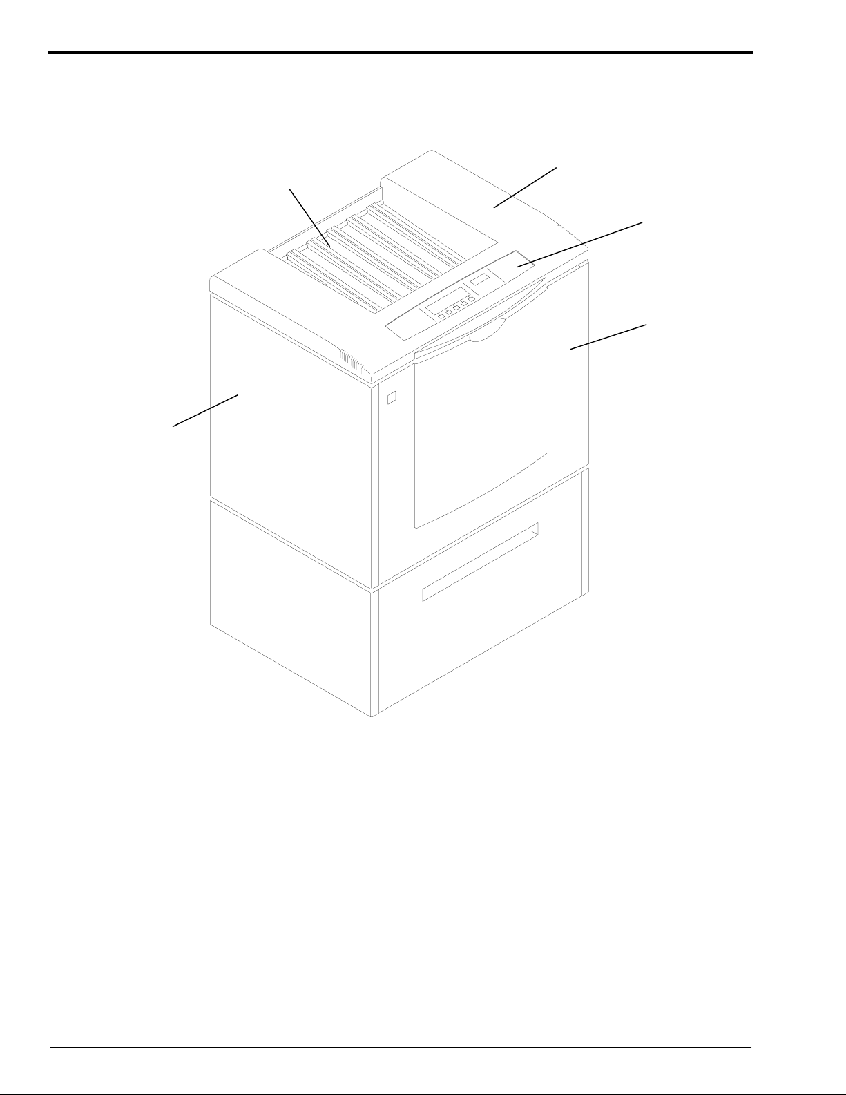
Identifying the Covers and Panels and Other Components of the Processor
Figure 1 Receive End of the Processor
Non-Drive
Side Panel
Receive
Tray
Top Cover
Display
Panel
Dryer
End
Panel
H150_0035DCA
H150_0035DA
6 30SEP98 – 5B6328
Page 7
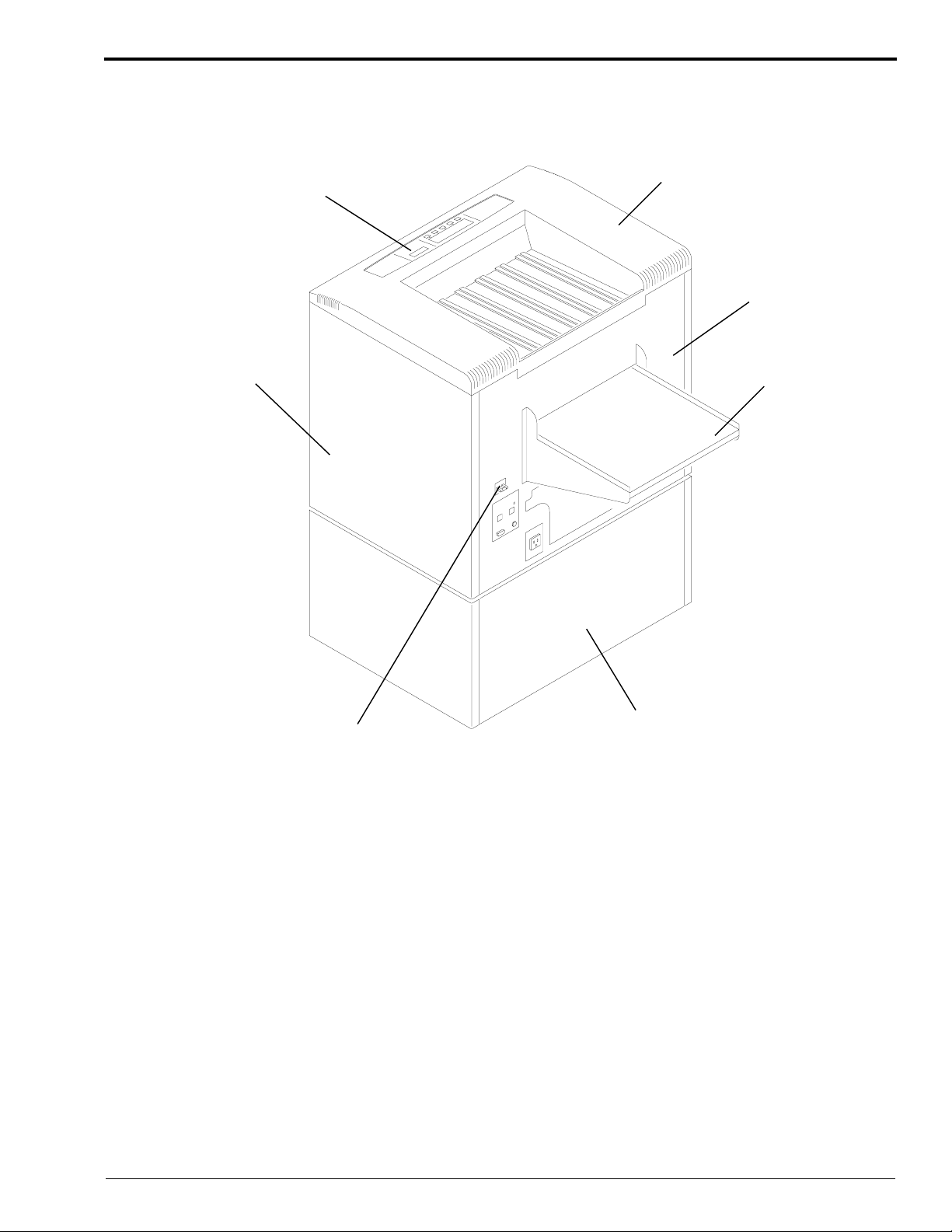
Figure 2 Feed End of the Processor
Display
Panel
Top Cover
Feed End
Panel
H150_0050DCA
H150_0050DA
Drive Side
Panel
Circuit
Breaker CB1
Feed Tray
Optional Stand
5B6328 – 30SEP98 7
Page 8
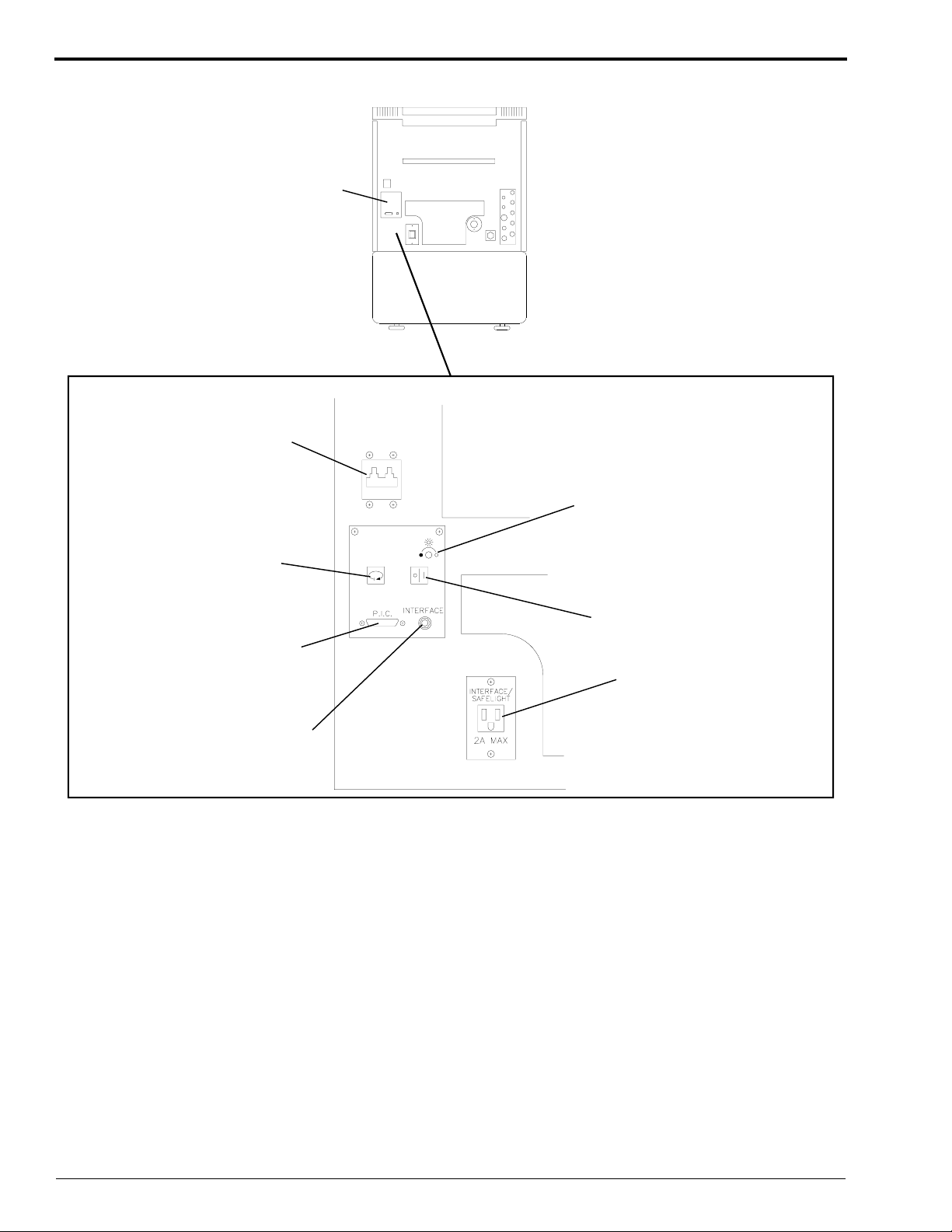
OPERATORS MANUAL
Figure 3 Circuit Breaker, Safelight Receptacle, and Interface Control Panel
Circuit
Breaker CB1
Interface
Control
Panel
Brightness
Adjustment
H150_0051DCA
H150_0051DA
Cycle
Selector
Processor
Interface
Connector
(RS-232 Part)
Interface
Phone Jack
Sleep/Wake Key
Safelight
Receptacle
8 30SEP98 – 5B6328
Page 9
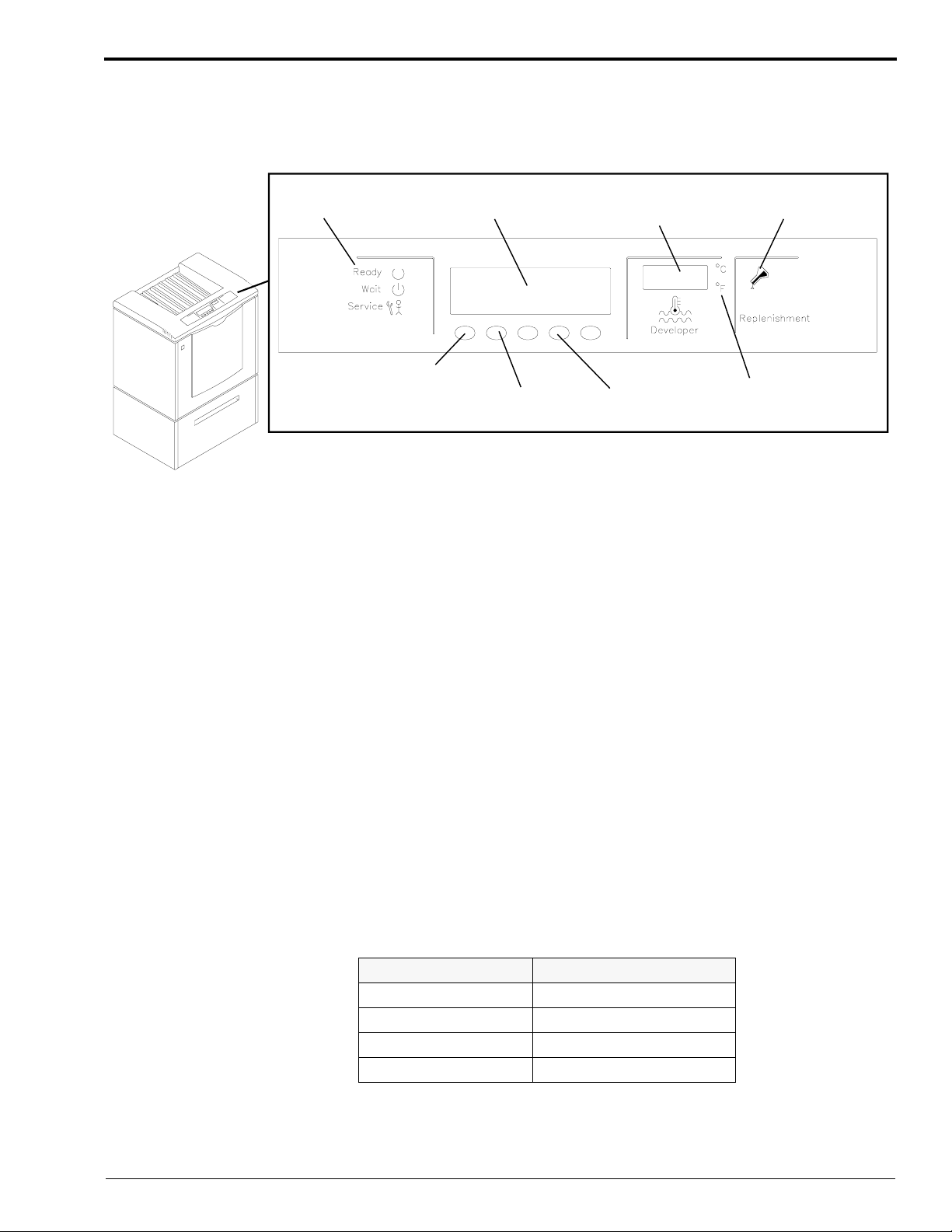
Using the Display Panel
The operator can select, change, and monitor processing variables for the Kodak X-Omat 3000 RA
Processor, using the Display Panel. See the figure below.
Figure 4 Display Panel
H150_0052BCA
H150_0052BA
Backlit
Messages
Soft
Key #1
Liquid Crystal
Display
Soft
Key #2
Developer
Temperature
Display
Soft
Key #4
Replenishment
Indicator
Degree C/F
Indicator
The Display Panel provides the following status information of the Processor:
• Ready, Wait, and Service Status Indicators
• Status/Error Messages
• Current cycle
• Current function for each of the Soft Keys
• Developer Temperature °C or °F Indicator, which provides the current temperature of the
developer in the Processor Tank
• Replenishment Indicator, which illuminates when both Replenishment Pumps are operating
Explanation of Status Indicators
The 3 Status Indicators provide the following information:
• If the Green “Ready” Indicator is illuminated, the Processor is ready to accept film.
• If the Yellow “Wait” Indicator is illuminated, the Processor has not yet reached optimum film
processing conditions.
• If the Red “Service” Indicator is illuminated, the Processor is in need of service.
A second set of Status Indicators, located on the feed end of the Processor, operate in the same way as
the Status Indicators on the Display Panel. Located below the Status Indicators on the feed end of the
Processor, is a second row of Indicators which indicate the current film processing cycle.
Indicator Illuminated Operating Cycle Selected
K K/RA
R Rapid
S Standard
E Extended
5B6328 – 30SEP98 9
Page 10

OPERATORS MANUAL
The Display Panel also has 5 keys called “Soft Keys.” These keys allow you to select, change, and
monitor Processor variables. These keys are located just below the message area of the Display Panel.
After you press a key to make a selection from the menus displayed, the functions of the first 4 keys
change to the next lower level of menu selections. Keys that are not used in a particular menu level
remain blank. Pressing the fifth key, “DONE/RETURN,” executes the function and causes the
previous menu level to be displayed.
Several characteristics of the Soft Keys to be aware of are:
1. All screens that allow you to change data or the configuration of the Processor display a “DONE/
RETURN” key, which allows you to return to the previous screen.
2. All options that allow you to change data, configuration, or affect the functionality of the Processor
take effect immediately after you release the key even if you do not press the DONE/RETURN key.
3. To modify numerical values, use the up and down arrow keys. Each time you press either the up
or down arrow key, the value will change by one unit. To scroll through an entire range of values
quickly, simply press and hold either the up or down arrow key.
MESSAGE
SOFT
KEY 1
SOFT
KEY 2
SOFT
KEY 3
CURRENT CYCLE
SOFT
KEY 4
SOFT
KEY 5
Adjusting the Contrast of the Display Panel
The Room Light Sensor disables the backlight on the Display Panel when the room is dark or if the Sensor is covered
by something such as papers or your hand. Whenever the backlight of the Display Panel is off, the 5 Soft Keys are
disabled to prevent you from making any inadvertent changes.
[1] To lighten the display, press and hold Soft Key 4 on the Display Panel. At the same time, press Soft Key 2 on
the Display Panel to obtain the desired contrast.
[2] To darken the display, press and hold Soft Key 4 on the Display Panel. At the same time, press Soft Key 1
on the Display Panel to obtain the desired contrast.
Adjusting the Intensity of the Interface Control Panel
The Light Intensity Adjustment Control allows you to change the brightness of the Indicators located on the feed end
of the Processor. If the room is brightly lit, no adjustment is available; the Indicators illuminate at full intensity.
When the room is dark or dimly lit, you can adjust the intensity by rotating the Adjustment Control.
[1] To brighten the intensity of the Indicators, rotate the Adjustment Control clockwise .
[2] To dim the intensity of the Indicators, rotate the Adjustment Control counterclockwise .
10 30SEP98 – 5B6328
Page 11

Using the Access Code
Only service personnel and one primary person should have use of the access code. The default
access code 4213 is required to perform certain functions.
Simply press the “GO TO SETUP” key on the Walk-Up Menu and enter the access code to perform
the functions listed below:
• to change setup information preset at the factory
• to change to or from the “K/RA” cycle
If the Limited Access Feature is off, an access code is not necessary to perform the functions listed
below:
• to select the Processor cycle (except “K/RA”)
• to change the Dryer temperature
• to display the current fixer temperature
• to place the Processor in Sleep Mode
• to display the time and date
The access code can be changed at any time by the user. To change the access code, follow the
procedure below. If you forget the new access code and need to revert back to the original access code,
call your service provider.
Changing the Access Code
[1] From the Walk-Up Menu, press the “GO TO SETUP” key.
READY
DRYER
TEMP
[2] Enter the 4-digit access code.
1234CANCEL
[3] Press the “MORE” key.
▲
[4] Press the “OPTIONS” key.
INFO SETUP
[5] Press the “MORE” key.
REPLEN
MODE
SLEEP SELECT
CYCLE
▼
DAILY
STARTUP
CYCLE MORE DONE/
OPTIONS DONE/
DISPLAY
UNITS
STD
MORE
MORE DONE/
GO TO
SETUP
REQUEST
RETURN
RETURN
RETURN
[6] Press the “ACCESS CODE” key.
ACCESS
CODE
5B6328 – 30SEP98 11
USER
ACCESS
TEMP
LOCK
MORE DONE/
RETURN
Page 12

OPERATORS MANUAL
[7] Enter the 4 digits of the new access code.
1234CANCEL
REQUEST
[8] Enter the same new 4-digit access code. A message will appear stating whether the new access code has been
accepted.
[9] Press the “DONE/RETURN” key repeatedly until you return to the display shown below. Then press the
“YES” key to return to the Walk-Up Menu.
EXIT SETUP?
YES CANCEL
REQUEST
Note
If you forget the new access code and need to revert to the original access code, call your service provider.
12 30SEP98 – 5B6328
Page 13

Limiting Access to the Processor Setup
Enabling the Limit Access feature prevents users from adjusting the Dryer temperature or changing the
processing cycle without first entering the access code. When this feature is selected, only those
operators who know the correct access code have the ability to change the dryer temperature or change
the processing cycle. While this feature is selected, the Cycle Change Switch on the feed end of the
Processor remains inactive.
Changing the User Access
[1] From the Walk-Up Menu, press the “GO TO SETUP” key.
READY
DRYER
TEMP
[2] Enter the 4-digit access code.
1234CANCEL
[3] Press the “MORE” key.
SLEEP SELECT
CYCLE
STD
MORE GO TO
SETUP
REQUEST
▲
[4] Press the “OPTIONS” key.
INFO SETUP
[5] Press the “MORE” key.
REPLEN
MODE
[6] Press the “USER ACCESS” key.
ACCESS
CODE
[7] Press the “LIMIT ACCESS” key.
CURRENT ACCESS IS LIMITED
LIMIT
ACCESS
▼
DAILY
STARTUP
USER
ACCESS
ALLOW
ACCESS
CYCLE MORE DONE/
RETURN
OPTIONS DONE/
RETURN
DISPLAY
UNITS
TEMP
LOCK
MORE DONE/
RETURN
MORE DONE/
RETURN
DONE/
RETURN
[8] Press the “DONE/RETURN” key repeatedly until you return to the display shown below. Then press the
“YES” key to return to the Walk-Up Menu.
EXIT SETUP?
YES CANCEL
REQUEST
5B6328 – 30SEP98 13
Page 14

OPERATORS MANUAL
Operating Characteristics
• All menus appearing before the point you are required to enter the access code give you only 20
seconds to press a key. If you do not press a key within that time, the Walk-Up Menu will appear.
• All menus appearing after the point you are required to enter the access code give you 2 minutes
to press a key. If you do not press a key within that time, the Walk-Up Menu will appear.
• When you first turn on the Processor, the wash water and Drive Motor run for 4 minutes and then
turn off. The Replenishment Pumps also turn on briefly.
• If either the developer or fixer solution evaporated while the Processor was off, the developer and
fixer tanks will be automatically replenished to their overflow levels when you turn on the
Processor.
• When film is fed, the Drive Motor and the Dryer Blower turn on immediately, and the water turns
on as soon as the first film reaches the Fixer/Wash Crossover.
• The Drive Motor will not operate if the Top Cover of the Processor is open.
• In an area that is dark or dimly lit, the room light Sensors on the Processor will detect the lack of
bright light and turn off the illuminated messages on the Display Panel to prevent the fogging of
the film which it “thinks” is being processed. The Soft Keys are also disabled if you use the
Processor in an area that is dark or dimly lit. If you would like the menu options and messages that
appear on the Display Panel to remain illuminated when the Processor is operating in a dark or
dimly lit room, contact your qualified service provider.
• All errors and warnings cause the alarm on the Processor to sound twice when a film is fed into the
Film Detector.
14 30SEP98 – 5B6328
Page 15
Operating Instructions
Performing the Daily Start-Up Procedure
Note
You can also program the Processor to turn on automatically by setting the Automatic On Timer. See Page 52 for
the procedure on how to program the Automatic Timers.
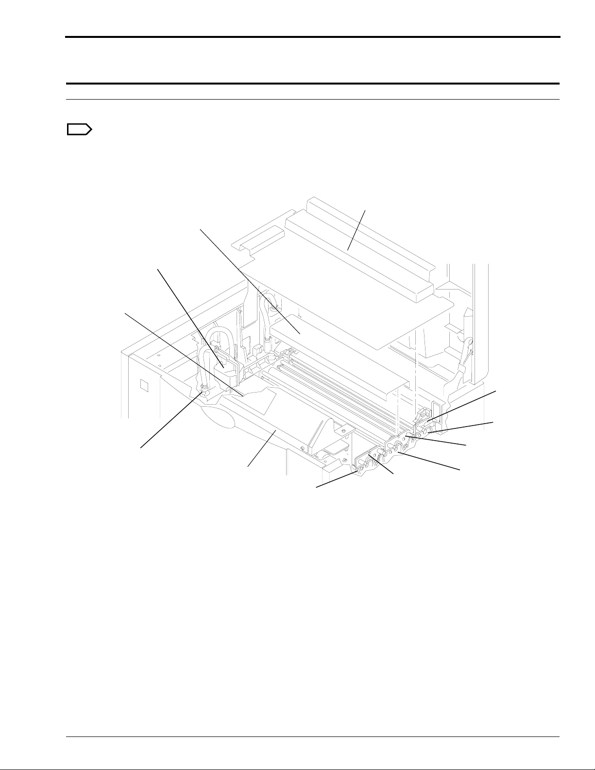
Figure 5 Checking the Positions of the Components
Wet Section
2 Evaporation
Covers
Water
Reservoir
Exit Rack
Cover
Detector
Crossover
Delevoper
Rack
Developer/Fixer
Crossover
Fixer
Rack
H150_0133HCB
H150_0133HA
Water
Disconnect
Dryer
Rack
Wash
Rack
Fixer/
Wash
Crossover
[1] Check that the Racks and Crossovers are in their correct positions.
[2] Check that the Water Reservoir is in position.
[3] Check that the 2 Crossover Troughs (not shown) are on the bottom of the Developer/Fixer and Fixer/Wash
Crossovers.
[4] Check that the Water Line is connected.
[5] Check that developer and fixer solutions are near the overflow levels of each Tank.
[6] Install the Evaporation Covers and the Wet Section Cover if they are not already installed.
[7] Close the Top Cover of the Processor.
5B6328 – 30SEP98 15
Page 16

OPERATORS MANUAL
Important
The incoming water temperature should be between 4 and 29°C (40 and 85°F).
[8] Turn on the water supply.
[9] Remove any film from the Feed Tray.
[10] Move the wall power switch to the “ON” position.
[11] Move the main Circuit Breaker CB1 to the “|” position.
[12] For optimum processing quality, allow approximately 20 minutes for the processing solutions to reach the
correct operating temperature before you feed film. The Ready Indicator will illuminate once the solutions have
reached the correct temperature.
Performing the Shutdown Procedure
Note
You can also program the Processor to shut down automatically by setting the Automatic Off Timer. See Page 52
for the procedure on how to set the Automatic Timers.
[1] Move the main Circuit Breaker CB1 to the “O” position.
[2] Move the wall power switch to the “OFF” position.
[3] Turn off the water supply.
16 30SEP98 – 5B6328
Page 17

Film Feeding
Sheet Film: See the figure for the recommended film-insertion procedure. Arrows indicate the
direction in which films should be fed into the Processor. Choose either the right or left edge of the
Feed Tray, and always feed films square with that edge of the Feed Tray.
Figure 6 X-Ray Film Sizes
Caution
• Feeding multiple films simultaneously will produce a film log error.
• Align films with either the right or left edge of the Feed Tray.
• Feed all single emulsion films, with the emulsion side up.
• Do not pull back films after you feed them into the Processor.
• Do not pull on film as it exits the Processor.
• Do not allow more than 80 sheets of films to accumulate in the Receive Tray at one time.
1 each
35 x 43 cm
or
14 X 17 in.
1 each
24 x 30 cm,
10 x 12 in., or
12.5 x 12.5 in.
1 each
24 x 24 cm
or
9 x 9 in.
1 each
35 x 35 cm
or
40 x 40 cm
1 each
18 x 43 cm
1 each
33 x 41 cm
30 x 40 cm,
30 x 35 cm,
11 x 14 in.,
or
12 x 15 in.
2 side
by side
18 x 43 cm
2 side
by side
18 x 24 cm
or
8 x 10 in.
H150_9000DC
1 each
18 x 24 cm
or
8 x 10 in.
2 side
by side
6.5 x 8.5 in.
2 side
by side
6.5 x 8.5 in.
3 side
by side
13 x 18 cm
4 x 5 in.,
3.5 x 8 in.,
5 x 7 in.
3 side
by side
10 x 10 cm
or
4 x 4 in.
5B6328 – 30SEP98 17
Page 18
OPERATORS MANUAL
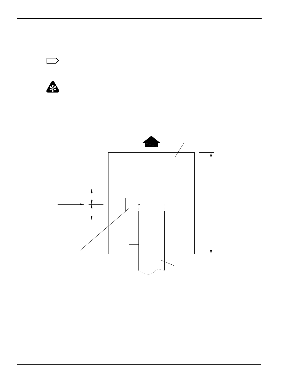
Roll Film: Use a sheet of film as a Leader. Make sure that the sheet film is as wide as, or wider than,
the roll film and at least 18 cm (7 in.) long.
Using 2.5 cm (1 in.) wide tape, such as 3M SCOTCH Brand Polyester Film Tape No. 850, fasten the
roll film, emulsion side up, to the Leader, making sure that the adhesive side of the tape is not exposed.
Most other types of tape are not acceptable, because their bases are soluble in the processing solutions.
Note
Tape the leading edge of the roll film, emulsion side up, within 5.1 cm (2 in.) of the vertical
(lengthwise) center of the Leader. See the figure.
Important
For reliable transport of the roll film, apply slight tension on both the feed and take-up ends of the roll
film, such as with a Kodak Roll Film Take-Up, Model 11.
Figure 7 Attaching a Leader to Roll Film
Direction of film travel
Leader
Vertical
(lengthwise)
center of
The Leader
Tape
5 cm (2 in.)
5 cm (2 in.)
90
>
_
18 cm (7 in.)
o
Roll film to be processed
H104_0551HCA
H104_0551HC
18 30SEP98 – 5B6328
Page 19

Default Setpoints and Configurations
Section 1: Summary of Default Settings
Setup information consists of the process setpoints and the film Processor configurations. All setup
information that was preset at the factory is listed in the tables below.
Setup information is stored in battery backed-up RAM (Random Access Memory). Therefore, you do
not need to program new values every time that you turn on the Processor. Even if power to the
Processor is interrupted or the Processor is turned off, you do not need to program the Processor.
If you wish, you may change the setup information by using the Soft Keys on the Display Panel. See
the following pages for instructions on how to set up the Processor.
Table 1 Default Processor Configurations for All Cycles
Access Code 4-2-1-3
Processing Cycle *Standard
Dryer Temperature *43°C (110°F)
Time and Date Operator Must Enter
Pump Calibration Operator Must Complete
Alarm Volume Mid Range (7)
Replenishment Mode
Temperature Lockout Mode
Display Units
Receptacle Mode Safelight Mode
Standby Mode
Display Language English
Access to Processor Setup Allowed
Sleep Mode Options
Roller Jog
Cool Down
Automatic On and Off Timers Off
*Operator Must Ensure That Setting is Correct for the Application.
Automatic
Disabled
°F, in./min
Interval
Off
Off
Summary of Default Settings
5B6328 – 30SEP98 19
Page 20

OPERATORS MANUAL
Table 2 Default Processor Setpoints for Each Cycle
Item
Developer
Temperature
Fixer Temperature
(minimum)
Developer
Replenishment
Volume
(35 x 43 cm sheet)
Automatic
Flooded
Fixer
Replenishment
Volume
(35 x 43 cm sheet)
Automatic
Flooded
Transport Speed
Dryer
Temperature
K/RA
(USA)
35.6°C
(96°F)
32.2°C
(90°F)
60 mL
65 mL
85 mL
65 mL
193.0 cm/min
(76 in./min)
43°C
(110°F)
K/RA
(Outside USA)
33.3°C
(92°F)
35°C
(95°F)
60 mL
65 mL
85 mL
65 mL
144.3 cm/min
(57 in./min)
43°C
(110°F)
RAPID STANDARD EXTENDED
37.2°C
(99°F)
35°C
(95°F)
60 mL
65 mL
85 mL
65 mL
144.8 cm/min
(57 in./min)
43°C
(110°F)
34.4°C
(94°F)
32.2°C
(90°F)
60 mL
65 mL
85 mL
65 mL
106.7 cm/min
(42 in./min)
43°C
(110°F)
34.4°C
(94°F)
29.4°C
(85°F)
60 mL
65 mL
85 mL
65 mL
53.3 cm/min
(21 in./min)
43°C
(110°F)
20 30SEP98 – 5B6328
Page 21

Section 2: Basic Setup Options
Selecting a Film Processing Cycle
Description:
The 3000 RA Processor offers 4 cycles to process film in the Processor: Extended, Standard, Rapid,
and K/RA. You may select the Extended, Standard, or Rapid cycle in either of 2 ways: by using the
Cycle Change Key or by using the Display Panel. The Cycle Change Key is located on the feed end of
the Processor. The Display Panel also provides you with a convenient means of selecting a cycle.
Selecting the Extended, Standard, or Rapid cycle does not require the use of the access code. The Kwik
(K/RA) cycle, which provides the fastest film processing time, is only available through the Display
Panel and does require use of the access code.
After you select a cycle, the microprocessor automatically adjusts the transport speed, replenishment
volumes, and solution temperatures to the programmed values for the selected cycle. When changing
from one cycle to another, you do, however, need to set the Dryer temperature to the lowest setting that
still provides good drying. See the procedure for setting the Dryer temperature on Page 25.
Table 3 Cycle Information for the Processor
Basic Setup Options
Film and
Cycle Process Time Drop Time
Kwik (K/RA)
USA
Kwik (K/RA)
Outside USA
Rapid
Standard
Extended
Cycle as used in this table, refers to the film processing cycle that is currently selected.
Process Time refers to the time it takes the leading edge of a 35 x 43 cm (14 x 17 in.) sheet of film to
travel from the Detector Rollers to the Exit Rollers of the Dryer Rack.
Drop Time refers to the time from the leading edge of a 35 x 43 cm (14 x 17 in.) sheet of film fed 43 cm
wide entering the Detector Rollers until the trailing edge exits the Dryer Rack.
Film and Chemicals refer to the combination of film and chemicals required for optimum image quality
when using the Processor. Kodak RP X-Omat Developer Replenisher and Kodak RP X-Omat Fixer and
Replenisher, or equivalents, may be used with the Extended, Standard, and Rapid cycles. Only
Kodak RA X-Omat Films and Chemicals may be used for the K/RA cycle. Contact your Kodak
representative to discuss the best option for your needs.
Throughput refers to the number of 35 x 43 cm (14 x 17 in.) sheets of film fed 43 cm wide that can be
processed in one hour.
52 seconds 63 seconds
69 seconds 83 seconds
69 seconds 83 seconds
93 seconds 112 seconds
183 seconds 222 seconds
Chemicals
RA Film and
Chemicals
RA Film and
Chemicals
RA or RP Film,
RP Chemicals
RA or RP Film,
RP Chemicals
RP Film and
Chemicals
Throughput
films/hour
270
201
201
148
74
5B6328 – 30SEP98 21
Page 22

OPERATORS MANUAL
Procedure for Selecting a Cycle Other Than K/RA:
[1] From the Walk-Up Menu, press the “SELECT CYCLE” key.
READY
DRYER
TEMP
[2] Press the appropriate key for the desired cycle.
SLEEP
SELECT
CYCLE
STD
MORE GO TO
SETUP
RAPID
CYCLE
[3] Press the “DONE/RETURN” key repeatedly until you return to the Walk-Up Menu.
STD
CYCLE
EXTD
CYCLE
DONE/
RETURN
Procedure for Selecting the K/RA Cycle:
[1] From the Walk-Up Menu, press the “GO TO SETUP” key.
READY
DRYER
TEMP
[2] Enter the 4-digit access code.
1234CANCEL
[3] Press the “CYCLE” key.
▲
[4] Press the “K/RA CYCLE” key.
SLEEP SELECT
CYCLE
▼
CYCLE MORE DONE/
MORE GO TO
SETUP
REQUEST
RETURN
STD
RAPID
CYCLE
[5] Press the “DONE/RETURN” key repeatedly until you return to the display shown below. Then press the
“YES” key to return to the Walk-Up Menu.
EXIT SETUP?
YES CANCEL
22 30SEP98 – 5B6328
STD
CYCLE
EXTD
CYCLE
K/RA
CYCLE
DONE/
RETURN
REQUEST
Page 23

Selecting the K/RA Cycle Setpoint Defaults
Description:
The Processor has 3 possible default cycle options. See Pages 21 and 22 for the setpoint defaults.
• U.S.
• Europe
• Japan
Default Setting: U.S.
Procedure:
[1] From the Walk-Up Menu, press the “GO TO SETUP” key.
READY
DRYER
TEMP
[2] Enter the 4-digit access code.
1234CANCEL
SLEEP SELECT
CYCLE
Basic Setup Options
STD
MORE GO TO
SETUP
REQUEST
[3] Press the “MORE” key.
▲
[4] Press the “OPTIONS” key.
INFO
[5] Press the “MORE” key.
REPLEN
MODE
[6] Press the “MORE” key.
ACCESS
CODE
[7] Press the “MORE” key.
STANDBY
MODE
▼
SETUP OPTIONS DONE/
DAILY
STARTUP
USER
ACCESS
ROLLER
JOG
CYCLE MORE DONE/
RETURN
RETURN
DISPLAY
UNITS
TEMP
LOCK
COOL
DOWN
MORE DONE/
RETURN
MORE DONE/
RETURN
MORE DONE/
RETURN
5B6328 – 30SEP98 23
Page 24

OPERATORS MANUAL
[8] Press the “CYCLE DEFAULT” key.
RECPT
MODE
ALARM
VOLUME
CYCLE
DEFAULT
MORE DONE/
RETURN
[9] Press the appropriate key.
U.S. EUROPE JAPAN DONE/
RETURN
[10] Press the “DONE/RETURN” key repeatedly until you return to the display shown below. Then press the
“YES” key to return to the Walk-Up Menu.
EXIT SETUP?
YES CANCEL
REQUEST
24 30SEP98 – 5B6328
Page 25

Setting the Dryer Setpoint Temperature
Description:
When selecting a Dryer temperature, always select the lowest temperature that still provides good film
drying. Films exiting the Processor should be “just dry” and cool to the touch in order to prevent
artifacts. You will find it necessary to adjust the Dryer temperature whenever you change the film
processing cycle and possibly when you change the type of film you are processing. You may choose
to have the Dryer temperature reading displayed in either metric units (degrees Celsius) or English units
(degrees Fahrenheit). To select the display units, see the procedure on Page 40.
Default Setting: 43°C (110°F)
Accepted Range: 21 - 66°C (70 - 150°F)
Procedure:
[1] From the Walk-Up Menu, press the “DRYER TEMP” key.
READY
DRYER
TEMP
[2] Use the up and down arrow keys to select the desired Dryer temperature.
SLEEP SELECT
CYCLE
MORE GO TO
Basic Setup Options
STD
SETUP
STD
120°F = DRYER SETPOINT
▲
[3] Press the “DONE/RETURN” key repeatedly until you return to the Walk-Up Menu.
▼
DONE/
RETURN
5B6328 – 30SEP98 25
Page 26

OPERATORS MANUAL
Setting the Time and Date
Description:
By setting the Clock in the Processor, you can take advantage of several of the features that the
Processor offers:
• Auto Start-Up and Shutdown
• Time and Date Stamping of Error Messages
When setting the time and date, you may choose from several different formats:
Time Formats:
• 12 Hour
• 24 Hour
Date Formats (where M=Month, D=Day, and Y=Year):
• M-D-Y
• D-M-Y
• Y-M-D
Procedure:
[1] From the Walk-Up Menu, press the “GO TO SETUP” key.
READY
DRYER
TEMP
[2] Enter the 4-digit access code.
1234CANCEL
[3] Press the “MORE” key.
▲
[4] Press the “SETUP” key.
INFO
[5] Press the “CLOCK” key.
PROCESS
SLEEP SELECT
CYCLE
▼
SETUP OPTIONS DONE/
CLOCK AUTO
CYCLE MORE DONE/
STARTUP
MORE GO TO
SETUP
REQUEST
RETURN
RETURN
PUMP
CALIB
DONE/
RETURN
STD
[6] Press the “TIME FORMAT” key.
SET
TIME
26 30SEP98 – 5B6328
SET
DATE
TIME
FORMAT
DATE
FORMAT
DONE/
RETURN
Page 27

[7] Select the “FORMAT” key of your choice.
12 HOUR = TIME DISPLAY FORMAT
Basic Setup Options
12 HOUR
FORMAT
[8] Press the “DONE/RETURN” key once to return to the format options.
[9] Press the “DATE FORMAT” key.
SET
TIME
[10] Select the “FORMAT” key of your choice.
M-D-Y = DATE DISPLAY FORMAT
M-D-Y
FORMAT
[11] Press the “DONE/RETURN” key once to return to the set time and set date options.
[12] Press the “SET TIME” key.
SET
TIME
[13] Use the up and down arrow keys to set the time in hours and minutes.
24 HOUR
FORMAT
SET
DATE
D-M-Y
FORMAT
SET
DATE
TIME
FORMAT
Y-M-D
FORMAT
TIME
FORMAT
DATE
FORMAT
DATE
FORMAT
DONE/
RETURN
DONE/
RETURN
DONE/
RETURN
DONE/
RETURN
12:30 AM = CURRENT TIME
▲
HOUR
[14] Press the “DONE/RETURN” key once to return to the set date option.
[15] Press the “SET DATE” key.
SET
TIME
[16] Press the “SET DATE” key.
SET
DATE
[17] Use the up and down arrow keys to set the date.
10-31 = CURRENT DATE
▲
MONTH
[18] Press the “DONE/RETURN” key once to return to the set year option.
▼
HOUR
SET
DATE
SET
YEAR
▼
MONTH
▲
MINUTE▼MINUTE
TIME
FORMAT
▲
DAY
DATE
FORMAT
▼
DAY
DONE/
RETURN
DONE/
RETURN
DONE/
RETURN
DONE/
RETURN
5B6328 – 30SEP98 27
Page 28

OPERATORS MANUAL
[19] Press the “SET YEAR” key.
SET
DATE
[20] Use the up and down arrow keys to set the year.
1995 = CURRENT YEAR
▲
YEAR
[21] Press the “DONE/RETURN” key repeatedly until you return to the display shown below. Then press the
“YES” key to return to the Walk-Up Menu.
EXIT SETUP?
YES CANCEL
SET
YEAR
▼
YEAR
DONE/
RETURN
DONE/
RETURN
REQUEST
28 30SEP98 – 5B6328
Page 29

Displaying the Time and Date
Description:
If you wish to display the current time and date, simply press the “TIME/DATE” key on the Display
Panel. The current time and date will then appear on the Display Panel.
Procedure:
[1] From the Walk-Up Menu, press the “MORE” key.
READY STD
Basic Setup Options
DRYER
TEMP
[2] Press the “TIME/DATE” key.
DISPLAY
FIX TEMP
[3] Press the “DONE/RETURN” key repeatedly until you return to the Walk-Up Menu.
SLEEP SELECT
CYCLE
TIME/
DATE
MORE GO TO
SETUP
DONE/
RETURN
5B6328 – 30SEP98 29
Page 30

OPERATORS MANUAL
Calibrating the Replenishment System
Description:
Calibrate the replenishment system every 3 months.
Calibrating the replenishment system determines the actual rate of the processing solution flowing
through the Replenishment Pumps. To calibrate the Pump you need to first measure the volume of
solution pumped during a set time period, and secondly enter the information into the microprocessor
by using the procedure outlined below. The microprocessor then computes the flow rate of the solution
through the Pump and adjusts the length of time that the Pump must operate so that the volume of
replenishment delivered equals the replenishment volume selected.
Important
The volume of replenishment solution actually measured during this procedure is not the volume
delivered for a 35 x 43 cm sheet of film.
Procedure:
[1] From the Walk-Up Menu, press the “GO TO SETUP” key.
READY
DRYER
TEMP
SLEEP SELECT
CYCLE
STD
MORE GO TO
SETUP
[2] Enter the 4-digit access code.
1234CANCEL
REQUEST
[3] Press the “MORE” key.
▲
[4] Press the “SETUP” key.
INFO
[5] Press the “PUMP CALIB” key.
PROCESS
[6] Press the “DEV CAL” key to calibrate the Developer Pump or the “FIX CAL” key to calibrate the Fixer Pump.
DEV
CAL
▼
SETUP OPTIONS DONE/
CLOCK AUTO
FIX
CAL
CYCLE MORE DONE/
RETURN
RETURN
STARTUP
PUMP
CALIB
DONE/
RETURN
DONE/
RETURN
30 30SEP98 – 5B6328
Page 31

Figure 8 Measuring the Replenishment Volume
Basic Setup Options
Developer
Replenishment
Replenishment
Calibration
Switch
Fixer
Replenishment
Hose
Graduated
Cylinder
Hose
Filter
Mandrel
H104_0259GCA
H104_0259GA
Caution
Wear protective eyewear when executing the following
procedure. Replenishment solutions are pumped
quickly and may splash.
[7] Open the Top Cover of the Processor.
[8] Insert the end of the Developer Replenishment (or
Fixer Replenishment) Hose into a Graduated
Cylinder.
[9] Hold the Graduated Cylinder over the wash
section of the Processor so that spills will not
contaminate the processing solutions.
[10] Press the Replenishment Calibration Switch on
the side wall of the Processor Tank.
[11] Measure and record the volume of replenishment
delivered by the system.
[12] Dispose of the solution in the Graduated Cylinder.
[13] Do Steps 8 through 11 at least 2 more times.
[14] Determine the average volume of replenishment
delivered.
[15] Install the Replenishment Hose into the developer
(or fixer) Filter Mandrel.
[16] Close the Top Cover of the Processor.
[17] Press the “UPDATE CAL VOL” key.
UPDATE
CAL VOL
DONE/
RETURN
[18] Use the up and down arrow keys to increase or decrease the volume displayed on the screen until the volume
displayed matches the average volume of replenishment as determined in Step 14.
60 mL = MEASURED DEVELOPER VOLUME
▲ ▼
DONE/
RETURN
[19] Press the “DONE/RETURN” key repeatedly to return to the menu shown below.
DEV
CAL
FIX
CAL
DONE/
RETURN
[20] Repeat Steps 6 through 18 to calibrate the fixer (or developer) replenishment.
[21] Press the “DONE/RETURN” key repeatedly until you return to the display shown below. Then press the
“YES” key to return to the Walk-Up Menu.
EXIT SETUP?
YES CANCEL
REQUEST
5B6328 – 30SEP98 31
Page 32

OPERATORS MANUAL
Selecting a Replenishment Mode
Description:
Automatic Replenishment Mode
Select this mode when you want the Processor to automatically adjust the replenishment volumes for
developer and fixer according to film usage. See the procedure “Setting the Developer and Fixer
Replenishment Volume” beginning on Page 48.
Flooded Replenishment Mode
Select this mode if your site has low film usage of less than 25 sheets of 35 x 43 cm (14 x 17 in.) film
or equivalent area per 8-hour day. Check with your Kodak representative to see whether the Flooded
Replenishment Mode is right for the film usage of the Processor. Replenishment will be added
automatically —
• every 5 minutes, achieving a minimum replenishment of 780 mL/hr while the Processor is on and
• when the equivalent film area of 35 x 43 cm (14 x 17 in.) has been processed.
Tank Fill Mode
Select this mode to fill empty Processor Tanks automatically. A warning error stating that the “Tanks
Currently Being Filled” occurs as the Tanks are filling. After the Tanks are filled, the error is cleared
and the Processor will begin normal operation.
Disable Replenishment
Select this feature to disable the Replenishment Pumps before doing any of the cleaning procedures.
When the Pumps are disabled, a warning error stating that the “Replenishment Pumps Disabled”
occurs. To clear the error, simply select either Automatic or Flooded Replenishment.
Default Setting: Automatic
Procedure:
[1] Press the “GO TO SETUP” key.
Note
The “SELECT CYCLE” key does not appear if you have selected the K/RA cycle.
READY
DRYER
TEMP
[2] Enter the 4-digit access code.
1234CANCEL
[3] Press the “MORE” key.
SLEEP SELECT
CYCLE
MORE GO TO
REQUEST
STD
SETUP
▲
[4] Press the “OPTIONS” key.
INFO SETUP
32 30SEP98 – 5B6328
▼
CYCLE MORE DONE/
RETURN
OPTIONS DONE/
RETURN
Page 33

[5] Press the “REPLEN MODE” key.
Basic Setup Options
REPLEN
MODE
DAILY
STARTUP
DISPLAY
UNITS
MORE DONE/
RETURN
[6] Select one of the 4 replenishment modes:
• Automatic Replenishment
• Flooded Replenishment
• Tank Fill
• Disable Replenishment
REPLENISHMENT MODE IS AUTO
AUTO FLOODED TANK
FILL
DISABLE
REPLEN
DONE/
RETURN
[7] Press the “DONE/RETURN” key repeatedly until you return to the display shown below. Then press the
“YES” key to return to the Walk-Up Menu.
EXIT SETUP?
YES CANCEL
REQUEST
5B6328 – 30SEP98 33
Page 34

OPERATORS MANUAL
Selecting the Standby Mode
Description:
The Processor will enter the Standby mode if no films are fed for approximately 15 seconds. There are
2 modes within the Standby mode — the Interval mode and the Continuous mode. With the Processor
in the Interval mode, the transport system and wash water turn on periodically to keep the Rollers wet.
When the Processor is in the Continuous mode, the transport system will operate continuously at a
reduced speed to keep the Rollers wet. In either mode, the following actions take place:
• the Dryer Blower and Heater turn on as needed to maintain the temperature of the Dryer
1
• the wash water turns on every 36
• the solution Heaters remain on as needed to maintain the setpoint temperature of the solutions
Default Setting: Interval
Procedure:
[1] From the Walk-Up Menu, press the “GO TO SETUP” key.
READY
DRYER
TEMP
SLEEP SELECT
⁄2 minutes to clean the Rollers
CYCLE
STD
MORE GO TO
SETUP
[2] Enter the 4-digit access code.
1234CANCEL
[3] Press the “MORE” key.
▲
[4] Press the “OPTIONS” key.
INFO SETUP
[5] Press the “MORE” key.
REPLEN
MODE
[6] Press the “MORE” key.
ACCESS
CODE
▼
DAILY
STARTUP
USER
ACCESS
REQUEST
CYCLE MORE DONE/
RETURN
OPTIONS DONE/
RETURN
DISPLAY
UNITS
TEMP
LOCK
MORE DONE/
RETURN
MORE DONE/
RETURN
[7] Press the “STANDBY MODE” key.
STANDBY
MODE
34 30SEP98 – 5B6328
ROLLER
JOG
COOL
DOWN
MORE DONE/
RETURN
Page 35

Basic Setup Options
[8] Press either key:
• the “INTER” key for the Interval Mode
• the “CONT” key for Continuous Mode
STANDBY MODE IS INTERVAL
INTER CONT DONE/
RETURN
[9] Press the “DONE/RETURN” key repeatedly until you return to the display shown below. Then press the
“YES” key to return to the Walk-Up Menu.
EXIT SETUP?
YES CANCEL
REQUEST
5B6328 – 30SEP98 35
Page 36

OPERATORS MANUAL
Setting the Volume of the Alarm
Description:
The Processor includes an audible alarm that signals the user when to feed films in order to ensure the
proper spacing of films. The alarm also signals the occurrence of an error or warning. The volume of
the alarm is adjustable among 15 different levels. As you increase or decrease the volume of the alarm,
the alarm sounds continuously so that you can hear the current volume level you selected. The alarm
continues to sound until you press the “DONE/RETURN” key or until the screen time-out expires.
Default Setting: Mid Range (7)
Accepted Range: 0 - 15
Procedure:
[1] From the Walk-Up Menu, press the “GO TO SETUP” key.
READY
DRYER
TEMP
[2] Enter the 4-digit access code.
SLEEP SELECT
CYCLE
STD
MORE GO TO
SETUP
1234CANCEL
[3] Press the “MORE” key.
▲
[4] Press the “OPTIONS” key.
INFO
[5] Press the “MORE” key.
REPLEN
MODE
[6] Press the “MORE” key.
ACCESS
CODE
[7] Press the “MORE” key.
REQUEST
▼
SETUP OPTIONS DONE/
DAILY
STARTUP
USER
ACCESS
CYCLE MORE DONE/
RETURN
RETURN
DISPLAY
UNITS
TEMP
LOCK
MORE DONE/
RETURN
MORE DONE/
RETURN
STANDBY
MODE
[8] Press the “ALARM VOLUME” key.
RECPT
MODE
36 30SEP98 – 5B6328
ROLLER
JOG
ALARM
VOLUME
COOL
DOWN
CYCLE
DEFAULT
MORE DONE/
RETURN
MORE DONE/
RETURN
Page 37

[9] To change the volume of the alarm, press the appropriate key:
•“
▲” key to increase the volume
•“
▼” key to decrease the volume
10 = ALARM VOLUME
Basic Setup Options
▲ ▼
[10] Press the “DONE/RETURN” key repeatedly until you return to the display shown below. Then press the
“YES” key to return to the Walk-Up Menu.
EXIT SETUP?
YES CANCEL
DONE/
RETURN
REQUEST
5B6328 – 30SEP98 37
Page 38

OPERATORS MANUAL
Selecting Temperature Lockout Mode
Description:
Turning Temperature Lockout ON automatically disables the transport system whenever the developer
temperature deviates from the specified temperature range. The transport system remains disabled
until the temperature of the developer is back within the specified temperature tolerance of ± 0.3°C
(0.5°F) of the setpoint.
Turning temperature Lockout OFF allows the Processor to accept film even when the developer
temperature deviates from the specified temperature range.
Default Setting: Off
Important
When using accessory equipment, the “Temperature Lockout” must be “OFF” to prevent the accessory
equipment from attempting to feed films with the transport off.
Procedure:
[1] From the Walk-Up Menu, press the “GO TO SETUP” key.
READY
DRYER
TEMP
SLEEP SELECT
CYCLE
STD
MORE GO TO
SETUP
[2] Enter the 4-digit access code.
1234CANCEL
[3] Press the “MORE” key.
▲
[4] Press the “OPTIONS” key.
INFO SETUP
[5] Press the “MORE” key.
REPLEN
MODE
[6] Press the “TEMP LOCK” key.
ACCESS
CODE
▼
DAILY
STARTUP
USER
ACCESS
REQUEST
CYCLE MORE DONE/
RETURN
OPTIONS DONE/
RETURN
DISPLAY
UNITS
TEMP
LOCK
MORE DONE/
RETURN
MORE DONE/
RETURN
[7] Press the “ON or OFF” key.
TEMPERATURE LOCKOUT IS ON
ON OFF DONE/
RETURN
38 30SEP98 – 5B6328
Page 39

Basic Setup Options
[8] Press the “DONE/RETURN” key repeatedly until you return to the display shown below. Then press the
“YES” key to return to the Walk-Up Menu.
EXIT SETUP?
YES CANCEL
REQUEST
5B6328 – 30SEP98 39
Page 40

OPERATORS MANUAL
Selecting Display Units for Temperature and Transport Speed
Description:
The software of the Processor allows you to choose either degrees Fahrenheit (°F) or degrees Celsius
(°C) for temperature units, and either English (in./min) or metric (cm/min) units for transport speed.
Default Setting: English °F and in./min
Procedure:
[1] From the Walk-Up Menu, press the “GO TO SETUP” key.
STD
READY
DRYER
TEMP
[2] Enter the 4-digit access code.
1234CANCEL
[3] Press the “MORE” key.
SLEEP SELECT
CYCLE
MORE GO TO
SETUP
REQUEST
▲
[4] Press the “OPTIONS” key.
INFO SETUP
[5] Press the “DISPLAY UNITS” key.
REPLEN
MODE
[6] Press either key:
• “ENGLISH” for °F and in./min or
• “METRIC” for °C and cm/min
UNITS ARE ENGLISH
ENGLISH METRIC DONE/
[7] Press the “DONE/RETURN” key repeatedly until you return to the display shown below. Then press the
“YES” key to return to the Walk-Up Menu.
▼
DAILY
SETUP
CYCLE MORE DONE/
RETURN
OPTIONS DONE/
RETURN
DISPLAY
UNITS
MORE DONE/
RETURN
RETURN
EXIT SETUP?
YES CANCEL
REQUEST
40 30SEP98 – 5B6328
Page 41

Selecting the Receptacle Mode
Description:
The Safelight Receptacle, which is located on the Feed End Panel (see Figure 3 on Page 8) can be set
to one of two modes:
• Safelight - receptacle power is on except when film is in the entrance area of the Processor.
Power is again returned after the trail edge of film has traveled 3 in. beyond the
Film Accumulator.
• Accessory - receptacle power is always on.
Default Setting: Safelight Mode
Procedure:
[1] From the Walk-Up Menu, press the “GO TO SETUP” key.
READY
DRYER
TEMP
[2] Enter the 4-digit access code.
SLEEP SELECT
CYCLE
Basic Setup Options
STD
MORE GO TO
SETUP
1234CANCEL
[3] Press the “MORE” key.
▲
[4] Press the “OPTIONS” key.
INFO SETUP
[5] Press the “MORE” key.
REPLEN
MODE
[6] Press the “MORE” key.
ACCESS
CODE
[7] Press the “MORE” key.
▼
DAILY
SETUP
USER
ACCESS
REQUEST
CYCLE MORE DONE/
RETURN
OPTIONS DONE/
RETURN
DISPLAY
UNITS
TEMP
LOCK
MORE DONE/
RETURN
MORE DONE/
RETURN
STANDBY
MODE
[8] Press the “RECEPT MODE” key.
RECEPT
MODE
5B6328 – 30SEP98 41
ROLLER
JOG
ALARM
VOLUME
COOL
DOWN
CYCLE
DEFAULT
MORE DONE/
RETURN
MORE DONE/
RETURN
Page 42

OPERATORS MANUAL
[9] Press either key:
• “SAFE” key for the Safelight mode or
• “ACCY” key for the Accessory mode
RECEPTACLE MODE IS SAFELIGHT
SAFE ACCY DONE/
RETURN
[10] Press the “DONE/RETURN” key repeatedly until you return to the display shown below. Then press the
“YES” key to return to the Walk-Up Menu.
EXIT SETUP?
YES CANCEL
REQUEST
42 30SEP98 – 5B6328
Page 43

Selecting the Display Language
Description:
The Processor displays messages in 12 different languages:
Danish Italian
Dutch Japanese
English Norwegian
Finnish Portuguese
French Spanish
German Swedish
Default Setting: English
Procedure:
[1] From the Walk-Up Menu, press the “GO TO SETUP” key.
READY
DRYER
TEMP
SLEEP SELECT
CYCLE
Basic Setup Options
STD
MORE GO TO
SETUP
[2] Enter the 4-digit access code.
1234CANCEL
[3] Press the “MORE” key.
▲
[4] Press the “OPTIONS” key.
INFO
[5] Press the “MORE” key.
REPLEN
MODE
[6] Press the “MORE” key.
ACCESS
CODE
REQUEST
▼
SETUP OPTIONS DONE/
DAILY
STARTUP
USER
ACCESS
CYCLE MORE DONE/
RETURN
RETURN
DISPLAY
UNITS
TEMP
LOCK
MORE DONE/
RETURN
MORE DONE/
RETURN
[7] Press the “MORE” key.
STANDBY
MODE
5B6328 – 30SEP98 43
ROLLER
JOG
COOL
DOWN
MORE DONE/
RETURN
Page 44

OPERATORS MANUAL
[8] Press the “MORE” key.
RECPT
MODE
ALARM
VOLUME
CYCLE
DEFAULT
[9] Press the “LANG” key.
LANG MORE DONE/
[10] Press the appropriate key to select the display language.
LANGUAGE IS ENGLISH
ENGLISH FRENCH GERMAN MORE DONE/
SPANISH
DANISH
PORTU
SWEDISH NORWEG MORE DONE/
DUTCH ITALIAN MORE DONE/
FINNISH JAPAN MORE DONE/
MORE DONE/
RETURN
RETURN
RETURN
RETURN
RETURN
RETURN
[11] Press the “DONE/RETURN” key repeatedly until you return to the display shown below. Then press the
“YES” key to return to the Walk-Up Menu.
EXIT SETUP?
YES CANCEL
REQUEST
44 30SEP98 – 5B6328
Page 45

Section 3: Advanced Setup Options
Setting the Developer and Fixer Setpoint Temperatures
Description:
Developer and fixer setpoint temperatures can be modified and stored for future use. Setpoints that
were preset at the factory always can be restored by pressing the “DEFAULT SETTING” key in Step 9.
Default Developer Setting: Varies with Cycle Selected
Default Fixer Setting: Varies with Cycle Selected
Procedure:
[1] From the Walk-Up Menu, press the “GO TO SETUP” key.
READY
DRYER
TEMP
[2] Enter the 4-digit access code.
SLEEP SELECT
CYCLE
MORE GO TO
SETUP
Advanced Setup Options
STD
1234CANCEL
[3] Press the “MORE” key.
▲
[4] Press the “SETUP” key.
INFO
[5] Press the “PROCESS” key.
PROCESS CLOCK AUTO
[6] Press the key for the current film processing cycle.
RAPID
CYCLE
[7] Press the “TEMP” key.
▼
SETUP OPTIONS DONE/
STD
CYCLE
CYCLE MORE DONE/
STARTUP
CYCLE
EXTD
PUMP
CALIB
K/RA
CYCLE
REQUEST
RETURN
RETURN
DONE/
RETURN
DONE/
RETURN
TEMP REPLEN
VOLUME
[8] Press either key:
• the “DEV TEMP” key to change the developer setpoint temperature
• the “FIX TEMP” key to change the fixer setpoint temperature
DEV
TEMP
5B6328 – 30SEP98 45
FIX
TEMP
SPEED DONE/
RETURN
DONE/
RETURN
Page 46

OPERATORS MANUAL
[9] To change the setpoint temperature, press the appropriate key:
•“
▲” key to increase the setpoint temperature
•“
▼” key to decrease the setpoint temperature
• “DEFAULT SETTING” key to return to the default setpoint temperature
• “CANCEL REQUEST” key to cancel the procedure
95.0° = DEVELOPER SETPOINT
▲ ▼
[10] Do Steps 8 and 9 for the fixer (or the developer) solution.
[11] Press the “DONE/RETURN” key repeatedly until you return to the display shown below. Then press the
“YES” key to return to the Walk-Up Menu.
EXIT SETUP?
YES CANCEL
DEFAULT
SETTING
CANCEL
REQUEST
DONE/
RETURN
REQUEST
Note
The setpoint temperature for the fixer solution is a minimum only; the temperature may rise above this setpoint.
46 30SEP98 – 5B6328
Page 47

Displaying the Fixer Temperature
Description:
If you wish to determine the temperature of the fixer solution, simply press the “DISPLAY FIX TEMP”
key on the Display Panel. The temperature reading will then be displayed for the fixer solution.
Note
The setpoint temperature for the fixer solution is a minimum only; the temperature may rise above this
setpoint.
Procedure:
[1] From the Walk-Up Menu, press the “MORE” key.
READY
DRYER
TEMP
[2] Press the “DISPLAY FIX TEMP” key.
SLEEP SELECT
CYCLE
Advanced Setup Options
STD
MORE GO TO
SETUP
DISPLAY
FIX TMP
[3] Press the “DONE/RETURN” key repeatedly until you return to the Walk-Up Menu.
TIME/
DATE
DONE/
RETURN
5B6328 – 30SEP98 47
Page 48

OPERATORS MANUAL
Setting the Developer and Fixer Replenishment Volumes
Description:
Default Developer Setting: Varies with Type of Replenishment Selected
Default Fixer Setting: Varies with Type of Replenishment Selected
If it is necessary to change the replenishment volumes from the factory default settings, follow the
procedure outlined below.
Procedure:
[1] From the Walk-Up Menu, press the “GO TO SETUP” key.
READY STD
DRYER
TEMP
[2] Enter the 4-digit access code.
1234CANCEL
[3] Press the “MORE” key.
▲
[4] Press the “SETUP” key.
INFO
[5] Press the “PROCESS” key.
PROCESS CLOCK AUTO
[6] Press the appropriate “CYCLE” key.
SLEEP SELECT
SETUP OPTIONS DONE/
▼
MORE GO TO
CYCLE
CYCLE MORE DONE/
PUMP
STARTUP
CALIB
SETUP
REQUEST
RETURN
RETURN
DONE/
RETURN
RAPID
CYCLE
[7] Press the “REPLEN VOLUME” key.
TEMP
[8] Press the “DEV or FIX REP VOLUME” key.
DEV REP
VOLUME
48 30SEP98 – 5B6328
STD
CYCLE
REPLEN
VOLUME
FIX REP
VOLUME
EXTD
CYCLE
SPEED DONE/
K/RA
CYCLE
DONE/
RETURN
RETURN
DONE/
RETURN
Page 49

Advanced Setup Options
[9] Press the appropriate key to change the replenishment volume:
•“
▲” key to increase the volume
•“
▼” key to decrease the volume
• “DEFAULT SETTING” key to return to the default volume
• “CANCEL REQUEST” key to cancel the procedure
60 mL = FIXER REPLENISHMENT VOLUME
▲ ▼
[10] Press the “DONE/RETURN” key repeatedly until you return to the display shown below. Then press the
“YES” key to return to the Walk-Up Menu.
EXIT SETUP?
YES CANCEL
DEFAULT
SETTING
CANCEL
REQUEST
DONE/
RETURN
REQUEST
Verifying the Replenishment Rates
[1] Open the Top Cover of the Processor.
[2] Insert the end of the Developer (or Fixer) Replenishment Hose into a Graduated Cylinder.
[3] Hold the Graduated Cylinder over the wash section of the Processor so that spills will not contaminate the
processing solutions.
[4] Press and hold for 5 seconds the Replenishment Calibration Switch located on the side wall of the Processor
Tank.
[5] Allow the Replenishment Pumps to turn on and deliver the preset volume of replenishment solution.
[6] Compare the volume of replenishment solution delivered into the Graduated Cylinder to the replenishment
volume you set in the previous procedure. If the 2 volumes are not within 10% of each other, do the
“Calibrating the Replenishment System” procedure on Page 30.
5B6328 – 30SEP98 49
Page 50

OPERATORS MANUAL
Setting the Transport Speed
Description:
Default Setting: Varies with Cycle Selected
Accepted Range: Varies with Cycle Selected
If it is necessary to change the default setting, follow the procedure outlined below.
Procedure:
[1] From the Walk-Up Menu, press the “GO TO SETUP” key.
READY
DRYER
TEMP
[2] Enter the 4-digit access code.
1234CANCEL
[3] Press the “MORE” key.
SLEEP SELECT
CYCLE
STD
MORE GO TO
SETUP
REQUEST
▲
[4] Press the “SETUP” key.
INFO
[5] Press the “PROCESS” key.
PROCESS CLOCK AUTO
[6] Press the appropriate “CYCLE” key.
RAPID
CYCLE
[7] Press the “SPEED” key.
TEMP
SETUP OPTIONS DONE/
CYCLE
REPLEN
VOLUME
▼
STD
CYCLE MORE DONE/
RETURN
RETURN
PUMP
STARTUP
EXTD
CYCLE
SPEED DONE/
CALIB
K/RA
CYCLE
DONE/
RETURN
DONE/
RETURN
RETURN
50 30SEP98 – 5B6328
Page 51

Advanced Setup Options
[8] Press the appropriate key to change the transport speed:
•“
▲” key to increase the speed
•“
▼” key to decrease the speed
• “DEFAULT SETTING” key to return to the default speed
• “CANCEL REQUEST” key to cancel the procedure
45 IN/MIN = SPEED SETPOINT
▲ ▼
[9] Press the “DONE/RETURN” key repeatedly until you return to the display shown below. Then press the
“YES” key to return to the Walk-Up Menu.
EXIT SETUP?
YES CANCEL
DEFAULT
SETTING
CANCEL
REQUEST
DONE/
RETURN
REQUEST
5B6328 – 30SEP98 51
Page 52

OPERATORS MANUAL
Setting the Automatic On and Off Timers
Description:
The Processor software provides you programmable timers so that you may program 2 distinct on and
off times for the Processor each day. The Automatic Timers allow you to specify a start time for the
Processor to energize automatically so that the processing solutions and the Dryer will have reached
their setpoint temperatures before you arrive at the work site. The Processor can store up to 2 “start
times” and 2 “off times” for each day of the week to coincide with changing shifts or with weekend
schedules.
Example of Use: For instance, if you would like the Processor to be warmed up and ready to accept
films by the time you arrive at work in the morning, you may set Timer1 to turn on the Processor at
6:00 a.m. If you operate during 2 distinct shifts and there is a large lapse in time between the 2 shifts,
you might want to set Timer1 to turn off the Processor at the end of the first shift. You might then want
to set Timer2 to turn on the Processor again an hour before the second shift starts for the afternoon.
And finally, you might want to set Timer2 to turn off the Processor for the night at the end of the second
shift.
Important
Do not set the On and Off Timers within 15 minutes of each other. To ensure the correct operation of
the Processor, the Processor must remain on for at least 15 minutes before the Automatic Off Timer
turns it off. Likewise, the Processor must remain off for at least 15 minutes before the Automatic On
Timer turns it on.
Procedure for Setting Timer1 Initially:
Note
If the Timers are already set and you wish to change the on and off times, follow the procedure on Page 56.
Before proceeding with the steps below, be sure that you have completed the procedure for setting the time and date
on Page 26.
If you are reading through the steps below to become familiar with the procedure and are not actually setting the
timers, the screens that you see displayed may be different from the sample screens shown in this procedure.
[1] From the Walk-Up Menu, press the “GO TO SETUP” key.
STD
READY
DRYER
TEMP
[2] Enter the 4-digit access code.
1234CANCEL
[3] Press the “MORE” key.
SLEEP SELECT
CYCLE
MORE GO TO
SETUP
REQUEST
▲
[4] Press the “SETUP” key.
INFO
52 30SEP98 – 5B6328
▼
SETUP OPTIONS DONE/
CYCLE MORE DONE/
RETURN
RETURN
Page 53

[5] Press the “AUTO STARTUP” key.
Advanced Setup Options
PROCESS
CLOCK AUTO
STARTUP
PUMP
CALIB
DONE/
RETURN
[6] If you have already set the clock, continue with Step 7. If you have not yet set the time and date, the display
below will appear. Do the procedure on Page 26 before continuing with this procedure.
CLOCK MUST BE SET BEFORE CONTINUING
DONE/
RETURN
[7] Press the “ON” key.
AUTO STARTUP IS OFF
ON OFF DONE/
RETURN
[8] Press the “SET TIMERS” key.
AUTO STARTUP IS ON
SET
TIMERS
ON OFF DONE/
RETURN
Setting the On Time
[9] Press the“TIMER1 CONTROL” key.
PRESS BUTTON TO SET UP FOR MONDAY
TIMER1
CONTROL
[10] Press the “ON” key.
SET UP TIMER1 FOR MONDAY
[11] Press the “ON TIME” key.
SET UP TIMER1 FOR MONDAY
ON
TIME
COPY
PREV
NEXT
DAY
DONE/
RETURN
ON OFF DONE/
RETURN
ON OFF DONE/
RETURN
5B6328 – 30SEP98 53
Page 54

OPERATORS MANUAL
[12] Use the up and down arrow keys to select the hour and minute when you want the Processor to turn on.
6:00 AM = CURRENT ON TIME
▲
HOUR
[13] Press the “DONE/RETURN” key to return to the menu options shown below.
SET UP TIMER1 FOR MONDAY
ON
TIME
Setting the Off Time
▼
HOUR
OFF
TIME
▲
MINUTE▼MINUTE
ON OFF DONE/
DONE/
RETURN
RETURN
Note
Any time the screen shown below appears on the Display Panel, you can press the “OFF” key to erase the last
programmed on and off times for Timer1 and Timer2.
[14] Press the “OFF TIME” key.
SET UP TIMER1 FOR MONDAY
ON
TIME
[15] Use the up and down arrow keys to select the hour and minute when you want the Processor to turn off.
11:00 AM = CURRENT OFF TIME
▲
HOUR
[16] Press the “DONE/RETURN” key repeatedly until you return to the menu options shown below.
PRESS BUTTON TO SET UP FOR MONDAY
TIMER1
CONTROL
OFF
TIME
▼
HOUR
TIMER2
CONTROL
ON OFF DONE/
RETURN
▲
MINUTE▼MINUTE
COPY
PREV
NEXT
DAY
RETURN
RETURN
DONE/
DONE/
Procedure for Setting Timer2 Initially
[1] Press the “TIMER2 CONTROL” key.
PRESS BUTTON TO SET UP FOR MONDAY
TIMER1
CONTROL
[2] Repeat Steps 10 through 16 starting on Page 53 to set the on and off times for Timer2. Then set the on and off
times for the remaining days of the week by completing the steps on the next page.
54 30SEP98 – 5B6328
TIMER2
CONTROL
COPY
PREV
NEXT
DAY
DONE/
RETURN
Page 55

Advanced Setup Options
Procedure for Setting the On and Off Timers for the Remaining Days of the Week
If the hours that you would like to operate the Processor on the other days of the week are the same hours as those
you set for Monday, follow Steps 1 through 3 below.
If you do not want to repeat Monday’s on and off times for the other days of the week, follow Steps 4 through 13 on
Page 55.
Copying On and Off Timer Settings
[1] Press the “NEXT DAY” key to advance the display to show Tuesday.
PRESS BUTTON TO SET UP FOR MONDAY
TIMER1
CONTROL
[2] Press the “COPY PREV” key. You will hear a beep when you press the “COPY PREV” key. If you would
like to ensure that Monday’s on and off times were repeated for the next day, do the steps below.
PRESS BUTTON TO SET UP FOR TUESDAY
TIMER1
CONTROL
TIMER2
CONTROL
COPY
PREV
COPY
PREV
NEXT
DAY
NEXT
DAY
DONE/
RETURN
DONE/
RETURN
[3] Repeat the entire process to set the Automatic Timers for the remaining days of the week.
Setting Different On and Off Times for the Remaining Days
If you want to select different on and off times for Timer1 and Timer2 than those you set for Monday, do the steps
below.
[4] Press the “NEXT DAY” key to advance the display to show Tuesday.
PRESS BUTTON TO SET UP FOR MONDAY
TIMER1
CONTROL
[5] Press the “TIMER1 CONTROL” key.
PRESS BUTTON TO SET UP FOR TUESDAY
TIMER1
CONTROL
[6] Press the “ON” key to enable Timer1.
SET UP TIMER1 FOR MONDAY
COPY
PREV
COPY
PREV
ON OFF DONE/
NEXT
DAY
NEXT
DAY
DONE/
RETURN
DONE/
RETURN
RETURN
[7] Press the “ON TIME” key.
5B6328 – 30SEP98 55
Page 56

OPERATORS MANUAL
SET UP TIMER1 FOR TUESDAY
ON
TIME
[8] Use the up and down arrow keys to select the hour and minute when you want the Processor to turn on.
2:00 PM = CURRENT ON TIME
▲
HOUR
[9] Press the “DONE/RETURN” key until you return to the menu options shown below.
Press the “OFF TIME” key.
SET UP TIMER1 FOR TUESDAY
ON
TIME
[10] Use the up and down arrow keys to select the hour and minute when you want the Processor to turn off.
▼
HOUR
OFF
TIME
ON OFF DONE/
RETURN
▲
MINUTE▼MINUTE
ON OFF DONE/
RETURN
RETURN
DONE/
11:00 PM = CURRENT OFF TIME
▲
HOUR
[11] Press the “DONE/RETURN” key twice to return to the menu options displayed below.
Press the “TIMER2 CONTROL” key.
PRESS BUTTON TO SET UP FOR TUESDAY
TIMER1
CONTROL
[12] Repeat Steps 7 through 11 to set the on and off time settings for Timer2.
[13] Repeat the entire process to set the Automatic Timers for the remaining days of the week.
▼
HOUR
TIMER2
CONTROL
▲
MINUTE▼MINUTE
COPY
PREV
NEXT
DAY
DONE/
RETURN
DONE/
RETURN
Changing the On and Off Timer Settings
Note
If you are setting the On and Off Timer Settings for the very first time, follow the procedure on Page 52.
[1] From the Walk-Up Menu, press the “GO TO SETUP” key.
STD
READY
DRYER
TEMP
SLEEP SELECT
CYCLE
MORE GO TO
SETUP
[2] Enter the 4-digit access code.
1234CANCEL
REQUEST
56 30SEP98 – 5B6328
Page 57

[3] Press the “MORE” key.
Advanced Setup Options
▲
[4] Press the “SETUP” key.
INFO
[5] Press the “AUTO STARTUP” key.
PROCESS
[6] Press the “SET TIMERS” key.
AUTO STARTUP IS ON
SET
TIMERS
[7] Press either the “TIMER1 CONTROL” or “TIMER2 CONTROL” key.
PRESS BUTTON TO SET UP FOR MONDAY
TIMER1
CONTROL
▼
SETUP OPTIONS DONE/
CLOCK AUTO
ON OFF DONE/
TIMER2
CONTROL
CYCLE MORE DONE/
PUMP
STARTUP
COPY
PREV
CALIB
NEXT
DAY
RETURN
RETURN
DONE/
RETURN
RETURN
DONE/
RETURN
[8] Press either the “ON TIME” or the “OFF TIME” key.
SET UP TIMER1 FOR MONDAY
ON
TIME
[9] Use the up and down arrow keys to select the new time that you want to program.
6:00 AM = CURRENT ON TIME
▲
HOUR
[10] Continue changing the programmed on and off times for Timer1 and Timer2 by pressing the “DONE/
RETURN” key repeatedly until you return to the appropriate menu.
SET UP TIMER1 FOR MONDAY
ON
TIME
OFF
TIME
▼
HOUR
OFF
TIME
ON OFF DONE/
RETURN
▲
MINUTE▼MINUTE
ON OFF DONE/
DONE/
RETURN
RETURN
5B6328 – 30SEP98 57
Page 58

OPERATORS MANUAL
Note
Any time the screen shown above appears on the Display Panel, you can press the “OFF” key to erase the last
programmed on and off times for Timer1 and Timer2.
[11] When you are through changing the on and off times, press the “DONE/RETURN” key repeatedly until you
return to the display shown below. Then press the “YES” key to return to the Walk-Up Menu.
EXIT SETUP?
YES CANCEL
REQUEST
58 30SEP98 – 5B6328
Page 59

Selecting the Start-Up Option
Description:
Selecting the Daily Start-Up option allows you to temporarily disable the Automatic Start-Up feature
of Sleep Mode. This feature provides you with a convenient, easy way to leave the Processor in Sleep
Mode for several days without needing to re-program the daily on and off timers.
Procedure:
[1] From the Walk-Up Menu, press the “GO TO SETUP” key.
READY
DRYER
TEMP
[2] Enter the 4-digit access code.
1234CANCEL
[3] Press the “MORE” key.
SLEEP SELECT
CYCLE
Advanced Setup Options
STD
MORE GO TO
SETUP
REQUEST
▲
[4] Press the “OPTIONS” key.
INFO
[5] Press the “DAILY STARTUP” key.
REPLEN
MODE
[6] Press the appropriate keys to select the day for which you wish to turn on or turn off the Automatic Start-Up
feature.
TUESDAY DAILY STARTUP ON
PREV
DAY
[7] Press the “DONE/RETURN” key repeatedly until you return to the display shown below. Then press the
“YES” key to return to the Walk-Up Menu.
▼
SETUP OPTIONS DONE/
DAILY
STARTUP
NEXT
DAY
CYCLE MORE DONE/
RETURN
RETURN
DISPLAY
UNITS
ON OFF DONE/
MORE DONE/
RETURN
RETURN
EXIT SETUP?
YES CANCEL
REQUEST
5B6328 – 30SEP98 59
Page 60

OPERATORS MANUAL
Entering and Exiting Sleep Mode
Description:
When the Processor is in Sleep Mode, the Processor appears to be “off,” but the microprocessor
remains active. Depending upon the configuration of other options, the components listed below
remain off while the Processor is in Sleep Mode:
• Heaters
• Motors
• Solenoids
While the Processor is in Sleep Mode, you cannot feed films or access any of the Processor setup
screens.
You can manually place the Processor in or out of Sleep Mode in either of 2 ways:
1. You may simply use the “Sleep/Wake” key located on the feed end of the Processor.
2. Or, you may use the Soft Keys on the Display Panel to place the Processor into or out of Sleep Mode.
60 30SEP98 – 5B6328
Page 61

Advanced Setup Options
Procedure for Entering Sleep Mode:
Note
When the Processor is in Sleep Mode, the backlight for the Display Panel is off. Press any key to illuminate the
Display Panel.
[1] From the Walk-Up Menu, press the “Sleep” key.
STD
READY
DRYER
TEMP
[2] Press the “YES” key to place the Processor in Sleep Mode or the “CANCEL REQUEST” key to quit.
ARE YOU SURE?
YES CANCEL
[3] If you have programmed the Automatic On and Off Timers under the “AUTO STARTUP” menu, the screen
below will be displayed when the Processor enters Sleep Mode. The screen remains displayed until the
Automatic Timer turns on or until you press the “WAKE” key.
SLEEP SELECT
CYCLE
MORE GO TO
SETUP
REQUEST
7:30 AM MONDAY = NEXT ON TIME
WAKE
If you have
“PROCESSOR IN SLEEP MODE.”
not programmed the Automatic On and Off Timers, the Processor will display the message
Procedure for Exiting Sleep Mode:
There are 3 different ways to take the Processor out of Sleep Mode:
[1] If you have programmed the Automatic On and Off Start-Up Timers, you can allow the pre-programmed On
Timer to return the Processor to normal operating condition at the specified time.
7:30 AM MONDAY = NEXT ON TIME
WAKE
[2] Press the “WAKE” key on the Display Panel.
[3] Press the “SLEEP/WAKE” key on the feed end of the Processor.
5B6328 – 30SEP98 61
Page 62

OPERATORS MANUAL
Selecting Sleep Mode Options
Description:
You can choose how the Sleep Mode feature operates by selecting or not selecting the Roller Jog and
the Cool Down options and by setting the values of the On and Off Timers for the Auto Start-Up
option.
The selection of the Roller Jog feature reduces chemical buildup on the Rack and Crossover Rollers.
When the Roller Jog feature is selected, the transport Motor and wash water activate periodically
supplying the Crossover Troughs with water. Therefore, it is recommended that you select the Roller
Jog option when operating the Processor in Sleep Mode.
The selection of the Cool Down feature prevents the condensation of processing solutions. When you
select the Cool Down feature, the Dryer Blower operates for 3 hours to exhaust the moist, warm air
from the Processor. Therefore, the Cool Down feature, like the Roller Jog feature, reduces the buildup
of chemicals on the Rack and Crossover Rollers. It is recommended that you also select the Cool Down
option when operating the Processor in Sleep Mode.
Default Settings: Roller Jog - Off
Cool Down - Off
Procedure for Turning On or Off the Roller Jog Option:
[1] From the Walk-Up Menu, press the “GO TO SETUP” key.
READY
DRYER
TEMP
[2] Enter the 4-digit access code.
1234CANCEL
[3] Press the “MORE” key.
▲▼
[4] Press the “OPTIONS” key.
INFO SETUP
[5] Press the “MORE” key.
REPLEN
MODE
SLEEP SELECT
CYCLE
CYCLE MORE DONE/
OPTIONS DONE/
DAILY
STARTUP
DISPLAY
UNITS
STD
MORE GO TO
SETUP
REQUEST
RETURN
RETURN
MORE DONE/
RETURN
[6] Press the “MORE” key.
ACCESS
CODE
62 30SEP98 – 5B6328
USER
ACCESS
TEMP
LOCK
MORE DONE/
RETURN
Page 63

[7] Press the “ROLLER JOG” key.
Advanced Setup Options
STANDBY
MODE
ROLLER
JOG
COOL
DOWN
MORE DONE/
RETURN
[8] Press either key:
• the “ON” key to enable the Roller Jog option
• the “OFF” key to disable the Roller Jog option
ON OFF DONE/
RETURN
[9] Press the “DONE/RETURN” key repeatedly until you return to the display shown below. Then press the
“YES” key to return to the Walk-Up Menu.
EXIT SETUP?
YES CANCEL
REQUEST
5B6328 – 30SEP98 63
Page 64

OPERATORS MANUAL
Procedure for Turning On or Off the Cool Down Option:
[1] From the Walk-Up Menu, press the “GO TO SETUP” key.
READY
DRYER
TEMP
[2] Enter the 4-digit access code.
1234CANCEL
[3] Press the “MORE” key.
SLEEP SELECT
CYCLE
MORE GO TO
STD
SETUP
REQUEST
▲
[4] Press the “OPTIONS” key.
INFO
[5] Press the “MORE” key.
REPLEN
MODE
[6] Press the “MORE” key.
ACCESS
CODE
[7] Press the “COOL DOWN” key.
STANDBY
MODE
[8] Press either key:
• the “ON” key to enable the Cool Down option
• the “OFF” key to disable the Cool Down option
▼
SETUP OPTIONS DONE/
DAILY
STARTUP
USER
ACCESS
ROLLER
JOG
CYCLE MORE DONE/
RETURN
RETURN
DISPLAY
UNITS
TEMP
LOCK
COOL
DOWN
MORE DONE/
RETURN
MORE DONE/
RETURN
MORE DONE/
RETURN
COOL DOWN IS ON
ON OFF DONE/
RETURN
[9] Press the “DONE/RETURN” key repeatedly until you return to the display shown below. Then press the
“YES” key to return to the Walk-Up Menu.
EXIT SETUP?
YES CANCEL
REQUEST
64 30SEP98 – 5B6328
Page 65

Usage Information
Obtaining the Developer Usage Volume
Description:
This procedure provides you with the total volume of developer used to fill the Processing Tank and
to replenish the developer since the screen was last reset.
[1] From the Walk-Up Menu, press the “GO TO SETUP” key.
READY
DRYER
TEMP
[2] Enter the 4-digit access code.
1234CANCEL
[3] Press the “MORE” key.
SLEEP SELECT
CYCLE
STD
MORE GO TO
SETUP
REQUEST
▲
[4] Press the “INFO” key.
INFO SETUP OPTIONS DONE/
[5] Press the “USAGE” key.
USAGE DIAG SW
[6] Press the “DEV USAGE” key. The current volume of developer used and the date that the accumulation began
will appear on the Display Screen.
DEV
USAGE
To clear the developer usage information, do the steps below.
[7] Press the “CLEAR USAGE” key to clear both the total volume usage and the usage rate.
CLEAR
USAGE
▼
FIXER
USAGE
USAGE
RATE
CYCLE MORE DONE/
RETURN
RETURN
MORE DONE/
VERSION
FILM
USAGE
SETUP
GROUPS
RETURN
DONE/
RETURN
DONE/
RETURN
5B6328 – 30SEP98 65
Page 66

OPERATORS MANUAL
[8] When prompted, “ARE YOU SURE?” press the appropriate key:
• the “YES” key to clear the developer usage information and reset it to zero.
• the “CANCEL REQUEST” to continue recording the developer usage volume without resetting the volume
to zero.
[9] Press the “DONE/RETURN” key repeatedly until you return to the display shown below. Then press the
“YES” key to return to the Walk-Up Menu.
EXIT SETUP?
YES CANCEL
REQUEST
66 30SEP98 – 5B6328
Page 67

Obtaining the Developer Usage Rate
Description:
This procedure provides you with the average volume of developer used to replenish a single sheet of
film processed.
[1] From the Walk-Up Menu, press the “GO TO SETUP” key.
READY
DRYER
TEMP
[2] Enter the 4-digit access code.
1234CANCEL
[3] Press the “MORE” key.
SLEEP SELECT
CYCLE
STD
MORE GO TO
SETUP
REQUEST
▲
[4] Press the “INFO” key.
INFO SETUP OPTIONS DONE/
[5] Press the “USAGE” key.
USAGE DIAG SW
[6] Press the “DEV USAGE” key.
DEV
USAGE
[7] Press the “USAGE RATE” key. The average volume of developer replenishment used per single sheet of film
processed will appear on the Display Screen.
CLEAR
USAGE
To clear the developer rate information, do the steps below.
[8] Press the “CLEAR USAGE” key to clear both the total volume usage and the usage rate.
▼
FIXER
USAGE
USAGE
RATE
CYCLE MORE DONE/
RETURN
RETURN
MORE DONE/
VERSION
FILM
USAGE
SETUP
GROUPS
RETURN
DONE/
RETURN
DONE/
RETURN
CLEAR
USAGE
5B6328 – 30SEP98 67
USAGE
RATE
DONE/
RETURN
Page 68

OPERATORS MANUAL
[9] When prompted, “ARE YOU SURE?” press the appropriate key:
• the “YES” key to clear the developer usage information and reset it to zero.
• the “CANCEL REQUEST” to continue recording the developer usage volume without resetting the volume
to zero.
[10] Press the “DONE/RETURN” key repeatedly until you return to the display shown below. Then press the
“YES” key to return to the Walk-Up Menu.
EXIT SETUP?
YES CANCEL
REQUEST
68 30SEP98 – 5B6328
Page 69

Obtaining the Fixer Usage Volume
Description:
This procedure provides you with the total volume of fixer used to fill the Processing Tank and to
replenish the fixer since the counter was last reset.
[1] From the Walk-Up Menu, press the “GO TO SETUP” key.
READY
DRYER
TEMP
[2] Enter the 4-digit access code.
1234CANCEL
[3] Press the “MORE” key.
SLEEP SELECT
CYCLE
STD
MORE GO TO
SETUP
REQUEST
▲
[4] Press the “INFO” key.
INFO SETUP OPTIONS DONE/
[5] Press the “USAGE” key.
USAGE DIAG SW
[6] Press the “FIXER USAGE” key. The current volume of fixer used and the date that the accumulation began
will appear on the Display Screen.
DEV
USAGE
To clear the fixer usage information, do the steps below.
[7] Press the “CLEAR USAGE” key to clear both the total volume usage and the usage rate.
CLEAR
USAGE
▼
FIXER
USAGE
USAGE
RATE
CYCLE MORE DONE/
RETURN
RETURN
MORE DONE/
VERSION
FILM
USAGE
SETUP
GROUPS
RETURN
DONE/
RETURN
DONE/
RETURN
5B6328 – 30SEP98 69
Page 70

OPERATORS MANUAL
[8] When prompted, “ARE YOU SURE?” press the appropriate key:
• the “YES” key to clear the fixer usage information and reset it to zero.
• the “CANCEL REQUEST” to continue recording the fixer usage volume without resetting the volume to
zero.
[9] Press the “DONE/RETURN” key repeatedly until you return to the display shown below. Then press the
“YES” key to return to the Walk-Up Menu.
EXIT SETUP?
YES CANCEL
REQUEST
70 30SEP98 – 5B6328
Page 71

Obtaining the Fixer Usage Rate
Description:
This procedure provides you with the average volume of fixer used to replenish a single sheet of film
processed.
[1] From the Walk-Up Menu, press the “GO TO SETUP” key.
READY
DRYER
TEMP
[2] Enter the 4-digit access code.
1234CANCEL
[3] Press the “MORE” key.
SLEEP SELECT
CYCLE
STD
MORE GO TO
SETUP
REQUEST
▲
[4] Press the “INFO” key.
INFO SETUP OPTIONS DONE/
[5] Press the “USAGE” key.
USAGE DIAG SW
[6] Press the “FIXER USAGE” key.
DEV
USAGE
[7] Press the “USAGE RATE” key.
CLEAR
USAGE
To clear the fixer rate information, do the steps below.
[8] Press the “CLEAR USAGE” key to clear both the total volume usage and the usage rate.
▼
FIXER
USAGE
USAGE
RATE
CYCLE MORE DONE/
RETURN
RETURN
MORE DONE/
VERSION
FILM
USAGE
SETUP
GROUPS
RETURN
DONE/
RETURN
DONE/
RETURN
CLEAR
USAGE
5B6328 – 30SEP98 71
USAGE
RATE
DONE/
RETURN
Page 72

OPERATORS MANUAL
[9] When prompted, “ARE YOU SURE?” press the appropriate key:
• the “YES” key to clear the developer usage information and reset it to zero.
• the “CANCEL REQUEST” to continue recording the developer usage volume without resetting the volume
to zero.
[10] Press the “DONE/RETURN” key repeatedly until you return to the display shown below. Then press the
“YES” key to return to the Walk-Up Menu.
EXIT SETUP?
YES CANCEL
REQUEST
72 30SEP98 – 5B6328
Page 73

Selecting the Film Size for Each Setup Group
Description:
This procedure allows you to select which film size you want displayed in each of the 3 film setup
groups.
Group 1 you may select between the metric size 35 x 43 cm or the English size 14 x 17 in.
Group 2 you may select between the metric size 13 x 18 cm or the English size 5 x 7 in.
Group 3 you may select between the metric roll film size 100/105 mm or the English roll film
size 3
Procedure:
[1] From the Walk-Up Menu, press the “GO TO SETUP” key.
READY
[2] Enter the 4-digit access code.
1
⁄2 in.
DRYER
TEMP
1234CANCEL
SLEEP SELECT
CYCLE
MORE GO TO
STD
SETUP
REQUEST
[3] Press the “MORE” key.
▲
[4] Press the “INFO” key.
INFO SETUP OPTIONS DONE/
[5] Press the “USAGE” key.
USAGE DIAG SW
[6] Press the “SETUP GROUPS” key.
DEV
USAGE
[7] Press the appropriate key:
• the “SHOW METRIC” key to select the metric film size for that group
• the “SHOW U.S.” key to select the English film size for that group
• the “NEXT GROUP” key to advance to the next film setup group
▼
FIXER
USAGE
CYCLE MORE DONE/
VERSION
FILM
USAGE
RETURN
RETURN
MORE DONE/
RETURN
SETUP
GROUPS
DONE/
RETURN
SHOW
METRIC
5B6328 – 30SEP98 73
SHOW
U.S.
NEXT
GROUP
DONE/
RETURN
Page 74

OPERATORS MANUAL
Obtaining Film Usage Rates
Description:
This procedure provides you with film usage information. You may obtain the quantity of films
processed since the counter was last reset for any film size you select.
Note
Before doing this procedure, be sure that you have completed the previous procedure on Page 73 that
allows you to determine which film size you wish to include in each setup group.
Procedure:
[1] From the Walk-Up Menu, press the “GO TO SETUP” key.
READY
DRYER
TEMP
[2] Enter the 4-digit access code.
1234CANCEL
SLEEP SELECT
CYCLE
STD
MORE GO TO
SETUP
REQUEST
[3] Press the “MORE” key.
▲
[4] Press the “INFO” key.
INFO SETUP OPTIONS DONE/
[5] Press the “USAGE” key.
USAGE DIAG SW
[6] Press the “FILM USAGE” key.
DEV
USAGE
▼
FIXER
USAGE
CYCLE MORE DONE/
RETURN
RETURN
MORE DONE/
VERSION
FILM
USAGE
SETUP
GROUPS
RETURN
DONE/
RETURN
74 30SEP98 – 5B6328
Page 75

[7] Press the appropriate key:
• the “
• the “
• the “SHEET COUNT” key to display the number of films processed
To clear the film usage information, do the steps below.
[8] Press the “CLEAR USAGE” key.
[9] When prompted, “ARE YOU SURE?” press the appropriate key:
• the “YES” key to clear the film usage information and reset it to zero.
• the “CANCEL REQUEST” to continue recording the film usage information without resetting it to zero.
[10] Press the “DONE/RETURN” key repeatedly until you return to the display shown below. Then press the
“YES” key to return to the Walk-Up Menu.
▲” key to display the usage count for the next largest film size
▼” key to display the usage count for the next smallest film size
▲ ▼
▲ ▼
CLEAR
USAGE
CLEAR
USAGE
SHEET
COUNT
SHEET
COUNT
DONE/
RETURN
DONE/
RETURN
EXIT SETUP?
YES CANCEL
REQUEST
5B6328 – 30SEP98 75
Page 76

OPERATORS MANUAL
Obtaining the Processor’s Software Version
Description:
This procedure allows you to determine what versions of software are operating in your Processor. You
may display the software version for the following programs:
• Boot
• Main
• Accumulator Boot
• Accumulator Main
Procedure:
[1] From the Walk-Up Menu, press the “GO TO SETUP” key.
READY
DRYER
TEMP
[2] Enter the 4-digit access code.
SLEEP SELECT
CYCLE
STD
MORE GO TO
SETUP
1234CANCEL
REQUEST
[3] Press the “MORE” key.
▲
[4] Press the “INFO” key.
INFO SETUP OPTIONS DONE/
[5] Press the “SW VERSION” key.
USAGE DIAG SW
[6] Press the appropriate key. The software version will appear on the Display Screen.
• the “BOOT” key to display the boot version
• the “MAIN” key to display the main program version
• the “ACCUM BOOT” key to display the accumulator boot version
• the “ACCUM MAIN” key to display the accumulator main program version
▼
CYCLE MORE DONE/
RETURN
RETURN
MORE DONE/
VERSION
RETURN
BOOT MAIN ACCUM
BOOT
76 30SEP98 – 5B6328
ACCUM
MAIN
DONE/
RETURN
Page 77

[7] When you are done displaying the different software versions, press the “DONE/RETURN” key repeatedly
until you return to the display shown below. Then press the “YES” key to return to the Walk-Up Menu.
EXIT SETUP?
YES CANCEL
REQUEST
5B6328 – 30SEP98 77
Page 78

OPERATORS MANUAL
Other Functions
Description:
There are a few other menu options that you might see that have not been discussed in this Operator
Manual. Two of the options appear on the display shown below. The operator should never have any
need to access these options. These options should be accessed only by a trained, service provider.
USAGE DIAG SW
VERSION
The “DIAG” key allows a trained, service provider access to the internal diagnostics that reside in the
Processor.
The “MORE” key allows a trained, service provider access to additional diagnostic functions and
provides the capability for the service provider to print error history logs.
MORE DONE/
RETURN
78 30SEP98 – 5B6328
Page 79

Replenishment Solutions
Mixing the Developer and Fixer Solutions
Important
• See Table 3 on Page 21 to determine which type of chemicals to use with the selected cycle.
• When mixing chemicals, follow all instructions and precautions.
• Do not mix more than a 2-week supply of developer and fixer replenisher.
[1] To ensure that replenishment does not occur while the solutions are being mixed, move the Main Circuit
Breaker CB1 to the “O” position.
[2] Determine which type of chemicals is needed for the film processing cycle that you selected. See the table on
Page 21.
[3] Following all directions provided with the solutions, mix at least 19 litres (5 gallons) of each solution.
Filling the Processor Tanks
[1] Check that the Racks are in the correct positions.
Figure 9 Checking the Positions of the Racks
Detector
Crossover
Assembly
Developer Rack
Developer/Fixer
Crossover
H150_0055HCA
H150_0055HA
Exit
Rack
Dryer
Rack
Fixer Rack
Fixer/Wash
Crossover
Wash Rack
[2] Close the Developer and Fixer Drains. See Figure 10 on Page 81.
Important
The Replenishment Pumps automatically start when the Processor is turned on.
[3] Move the main Circuit Breaker CB1 to the “|” position.
[4] Wait for the Walk-Up Menu to appear on the Display Panel.
5B6328 – 30SEP98 79
Page 80

OPERATORS MANUAL
[5] From the Walk-Up Menu, press the “GO TO SETUP” key.
READY
DRYER
TEMP
[6] Enter the 4-digit access code.
1234CANCEL
[7] Press the “MORE” key.
SLEEP SELECT
CYCLE
STD
MORE GO TO
SETUP
REQUEST
▲
[8] Press the “OPTIONS” key.
INFO
[9] Press the “REPLEN MODE” key.
REPLEN
MODE
▼
SETUP OPTIONS DONE/
DAILY
STARTUP
CYCLE MORE DONE/
RETURN
RETURN
DISPLAY
UNITS
MORE DONE/
RETURN
Important
• If the developer and fixer Tanks of the Processor are empty and you do not press “TANK FILL,” a “Fill Error”
will occur in approximately 4 minutes.
• The developer and fixer Tanks will not fill if the Top Cover is open.
• The developer and fixer Tanks require approximately 10 minutes to fill with solution.
• An Tank Fill error message will appear on the Display Panel while the Tanks are filling.
• Once the Tanks are full, the Replenishment Pumps automatically turn off and the normal, Processor warm-up
period begins.
[10] Press the “TANK FILL” key.
AUTO FLOODED TANK
FILL
[11] Press the “DONE/RETURN” key repeatedly until you return to the Walk-Up Menu.
[12] If you are using RP chemicals, wait until the Tanks have been filling for approximately 1 minute. Then
add 190 mL (6.5 fl oz) of starter solution to the drive side of the Processor’s developer Tank.
[13] After the Replenishment Pumps stop operating, check that:
(a) the level of both the developer and fixer solutions in the Tanks is at the overflow limit.
(b) there is some movement on the surface of the developer and fixer solutions to indicate that the
Recirculation Pump is operating.
80 30SEP98 – 5B6328
DISABLE
REPLEN
DONE/
RETURN
Page 81
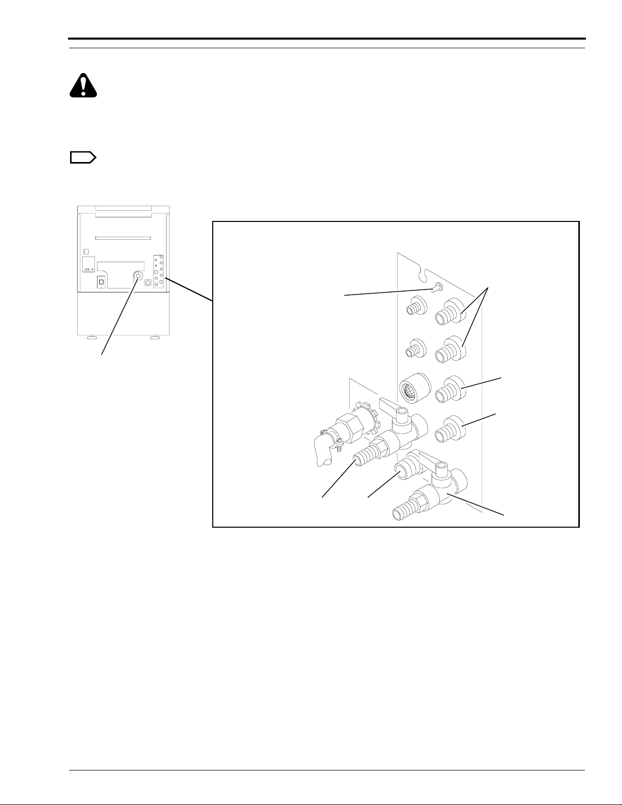
Draining the Processor Tanks
Warning
Check that the Drain and Drain tubing meet all the requirements outlined in the Site Specifications,
Publication No. 5B6329.
[1] Open the Fixer and Developer Drain Valves.
Note
The Wash Tank does not need to be drained.
Figure 10 Opening or Closing the Fixer and Developer Drain Valves
Recirculated
Silver Recovery
Equipotential
Grounding Lug
Air
Exhaust
H150_0227HCA
H150_0227HA
Developer
Drain
WASH
Drain
Developer
Overflow
Fixer
Overflow
Fixer Drain
5B6328 – 30SEP98 81
Page 82

OPERATORS MANUAL
82 30SEP98 – 5B6328
Page 83

Menu Flowchart
5B6328 – 30SEP98 83
Page 84

OPERATORS MANUAL
120 F = DRYER SETPOINT
V
V
STD
DONE/
RETURN
READY
DRYER
TEMP
PRESS BUTTON TO SELECT
RAPID
CYCLE
PRESS BUTTON TO SELECT
RAPID
CYCLE
STD
CYCLE
STD
CYCLE
EXTD
CYCLE
EXTD
CYCLE
(WALK UP MENU)
SELECT
SLEEP
K/RA
CYCLE
CYCLE
RETURN
RETURN
MORE
ENTER ACCESS CODE OR
STD
DONE/
120 F = DRYER SETPOINT
PRESS BUTTON TO SELECT
STD
DONE/
STD
GO TO
SETUP
CANCEL REQUEST
1
2
V
V
INFO
SETUP
3
CYCLE
OPTIONS
4
MORE
ACCY
CANCEL
REQUEST
STD
DONE/
RETURN
DONE/
RETURN
FILM IN PROCESS
DRYER
TEMP
TIME/
DISPLAY
DATE
FIX TEMP
MIXER LEVELS FOR 5000 RA/ICM ONLY
96.1 = CURRENT FIXER TEMPERATURE
15:06 12/25/95
MIXER
LEVELS
MORE
STD
STD
DONE/
RETURN
STD
DONE/
RETURN
STD
DONE/
RETURN
A
B
C
H150_9028EC
84 30SEP98 – 5B6328
Page 85

A
PRESS BUTTON TO SELECT
REPLEN
DAILY
MODE STARTUP
DISPLAY
UNITS
MORE
DONE/
RETURN
To Page 5
REPLENISHMENT MODE IS AUTOMATIC
B
C
12345 GAL
CLEAR
USAGE
FLOODED
USAGE
RATE
TANK
FILL
10/21/95
DISABLE
REPLEN
DONE/
RETURN
DONE/
RETURN
TUESDAY DAILY STARTUP ON
PREV
NEXT
DAY
CLEAR
USAGE
ON OFF ENGLISH METRICAUTO
DAY
PRESS BUTTON TO SELECT
USAGE DIAG
05/13/95
USAGE
RATE
DONE/
RETURN
SW
MORE
VERSION
PRESS BUTTON TO SELECT
DEV
FIXER
USAGE
USAGE
DONE/
RETURN
UNITS ARE ENGLISH
DONE/
RETURN
FILM
SETUP
USAGE
GROUPS
99999 = 6.5 x 8.5 IN34567 L
V
V
9999999 = SHEET COUNT
DONE/
RETURN
CLEAR
USAGE
To Page 3
SHEET
COUNT
DONE/
RETURN
DONE/
RETURN
12/28/95
DONE/
RETURN
14 x 17 IN = GROUP1
SHOW
SHOW
METRIC
U.S.
NEXT
GROUP
DONE/
RETURN
85 ML = DEV USAGE/SHEET
RETURN
254 ML = FIXER USAGE/SHEET
DONE/
DONE/
RETURN
5 x 7 IN = GROUP2
SHOW
SHOW
METRIC
U.S.
100/105 MM = GROUP3
SHOW
SHOW
METRIC
U.S.
NEW
GROUP
NEXT
GROUP
DONE/
RETURN
DONE/
RETURN
H150_9029EC
5B6328 – 30SEP98 85
Page 86

OPERATORS MANUAL
PRESS BUTTON TO SELECT
DEV
FIX
TEMP
TEMP
95.0 F = FIXER SETPOINT
V
DEFAULT
V
SETTING
CANCEL
REQUEST
PRESS BUTTON TO SELECT
RAPID
CYCLE
PRESS BUTTON TO SELECT
TEMP
STD
DONE/
RETURN
STD
DONE/
RETURN
DEV REP
PRESS BUTTON TO SELECT
PROCESS
EXTD
STD
CYCLE
CYCLE
REPLEN
SPEED
VOLUME
45 IN/MIN = SPEED SETPOINT
V
PRESS BUTTON TO SELECT
FIX REP
VOLUME
VOLUME
CLOCK
K/RA
CYCLE
V
AUTO
STARTUP
DONE/
RETURN
STD
DONE/
RETURN
DEFAULT
SETTING
CANCEL
REQUEST
STD
DONE/
RETURN
PUMP
CALIB
DONE/
RETURN
STD
DONE/
RETURN
PRESS BUTTON TO SELECT
TIME
12:30 AM = CURRENT TIME
V
HOUR MINUTE
HOUR
PRESS BUTTON TO SELECT
SET DONE/
DATE
1995 = CURRENT YEAR
V
SET
YEAR
YEAR
V
MINUTE
V DONE/
V
V
SETSET
RETURN
DONE/
RETURN
DONE/
RETURNYEAR
TIME DATE
DONE/
RETURNFORMAT
FORMATDATE
M-D-Y = DATE DISPLAY FORMAT
FORMAT
FORMAT
12 HOUR = TIME DISPLAY FORMAT
24 HOUR
12 HOUR
FORMAT
FORMAT
M-D-YM-D-Y M-D-Y
FORMAT
RETURN
RETURN
A
B
DONE/
95.0 F = DEVELOPER SETPOINT
V
DEFAULT
V
SETTING
H150_9030EC
CANCEL
REQUEST
STD
DONE/
RETURN
REQUEST
CANCEL
STD
DONE/
RETURN
STD
DONE/
RETURN
60 ML = DEVELOPER REPLENISHMENT VOLUME
V
60 ML = FIXER REPLENISHMENT VOLUME
V
DEFAULT CANCEL
V
SETTING
DEFAULT
V
SETTING REQUEST
10/31 = CURRENT DATE
V
V
MONTH
MONTH
V
V
DONE/
DAY
DAY RETURN
86 30SEP98 – 5B6328
Page 87

A
B
AUTO STARTUP IS ON
SET
ON OFF
TIMERS
PRESS BUTTON TO SETUP FOR MONDAY
TIMER2
TIMER1
CONTROL
CONTROL
SETUP TIMER FOR MONDAY
ON OFF
TIME
TIME
12:30 AM = CURRENT ON TIME
V
V
HOUR MINUTE
HOUR
If timer 1 or timer 2 is off, the "ON TIME"
*
and "OFF TIME" buttons will be blank.
COPY
PREV
MINUTE
PRESS BUTTON TO SELECT
FIX
DEV
CAL
CAL
DONE/
RETURN
NEXT
DONE/
DAY
RETURN
DONE/
OFFON
RETURN
V
V
DONE/
RETURN
PRESS REPLEN CAL SWITCH TO START CAL
UPDATE
CAL VOL
60 ML = MEASURED FIXER VOLUME
V
V
60 ML = MEASURED DEVELOPER VOLUME
V
V
DONE/
RETURN
DONE/
RETURN
DONE/
RETURN
DONE/
RETURN
H150_9031EC
5B6328 – 30SEP98 87
Page 88

OPERATORS MANUAL
ENTER NEW ACCESS CODE
12
STANDBY MODE IS INTERVAL
INTER CONT
3
RECEPTACLE MODE IS SAFELIGHT
SAFE
ACCY
4
CANCEL
REQUEST
DONE/
RETURN
PRESS BUTTON TO SELECT
USER
ACCESS
CODE
ACCESS IS CURRENTLY ALLOWED
LIMIT
ACCESS
ACCESS RETURN
ROLLER JOG IS ON
ON OFF
10 = CURRENT ALARM VOLUME
DONE/
RETURN
TEMP
MORE
LOCK
DONE/ALLOW
DONE/
RETURN
V
V
DONE/
RETURNACCESS
TEMPERATURE LOCKOUT IS ON
OFF
ON
COOL DOWN IS ON
ON
OFF
DONE/
RETURN
PRESS BUTTON TO SELECT
STANDBY
DONE/
RETURN
DONE/
RETURN
PRESS BUTTON TO SELECT
RECEPT
MODE
PRESS BUTTON TO SELECT
LANG
ALARM
VOLUME
MODE
CYCLE
DEFAULT
ROLLER COOL
JOG
DOWN
DONE/
MORE
RETURN
DONE/
MORE
RETURN
DONE/
MORE
RETURN
to first option screen
H150_9032EC
CURRENT CYCLE DEFAULTS ARE U.S.
EUROPE
JAPAN
U.S.
DONE/
RETURN
LANGUAGE IS ENGLISH
ENGLISH MORE
FRENCH GERMAN
LANGUAGE IS ENGLISH
SPANISH SWEDISH MORENORWEG
LANGUAGE IS ENGLISH
DUTCH MOREITALIAN
DANISH
LANGUAGE IS ENGLISH
FINNISH MOREJAPAN
PORTU
DONE/
RETURN
DONE/
RETURN
DONE/
RETURN
DONE/
RETURN
88 30SEP98 – 5B6328
Page 89

Preventive Maintenance
H108_0035AA
H108_0035ACD
Tray
Drip
Rack
Guard
Splash
Weekly
Important
Reliable operation of the Processor requires that you clean, adjust, and lubricate all parts correctly. More frequent
maintenance may be necessary because of site conditions or actual usage. The following guidelines are for
Processors installed according to the specifications in this publication. For monthly and quarterly maintenance,
contact your trained service personnel.
Warning
Wear rubber gloves, safety glasses, and protective clothing when doing any daily maintenance procedure. Report
any change in the operating condition of the Processor to your service personnel.
[1] Move the main Circuit Breaker CB1 on the Processor to the “O” position and
the wall power switch to the “OFF” position.
[2] Turn off the water supply.
[3] Lift the Top Cover.
Caution
• Handle these assemblies carefully to prevent changing the alignment. Do not wash the Racks and Crossovers
with water hotter than 44°C (110°F). Do not clean the Racks, Crossovers, or Squeegee Rollers using abrasive
materials or alcohol.
• To prevent fixer or developer contamination when you remove the Fixer or Developer Rack, place the Splash
Guard between the developer and fixer Tanks. Use the Rack Drip Tray when you remove or install any of the
Racks.
Figure 11 Using the Splash Guard and Drip Tray
5B6328 – 30SEP98 89
Page 90

OPERATORS MANUAL
[4] Remove the following parts from the Processor.
• Wet Section Cover
• Evaporation Covers
• Water Reservoir
• all Crossovers
• Wash Rack
[5] Rinse the 3 Crossovers, Troughs, Water Reservoir, and the Wash Rack with warm water, no hotter than 44°C
(110°F). Wipe the Rollers and the Guide Shoes with a damp, soft, synthetic sponge.
[6] Allow the Detector Crossover to air dry before you install it in the Processor.
[7] Wipe any chemical deposits from the processing section of the Processor.
[8] Check that all Rollers on all Crossovers and on the Wash Rack rotate freely. Check the squareness of the
Crossovers and the Wash Rack.
[9] Check that the Crossover Troughs are not broken or cracked.
[10] Install the following parts into the Processor. Check that each assembly is firmly seated.
• Wash Rack
• all Crossovers
• Water Reservoir
• Evaporation Covers
• Wet Section Cover
[11] Turn the Processor on and check for correct operation.
[12] Process a test film and check the transport assemblies.
Figure 12 Installing the Racks and Crossovers
Wash
Rack
Fixer/Wash
Crossover
Evaporation
Covers
Detector Crossover
Developer Rack
Developer/Fixer
Crossover
Fixer Rack
H104_0072BCG
H104_0072BA
90 30SEP98 – 5B6328
Page 91

Problem Solving
Transport Failure
Surface Artifacts
Abnormal Film Densities
Wet Films
Low Solution Levels
Overlapping of Films
• • Film Feeding Error
Feed only single thicknesses of film. Feed next film only after film feed
signal. If there is no film feed signal, refer the difficulty to qualified
personnel.
••••
• •
••
•• • Check that all Dryer Air Tubes are installed.
• •
• •••
•
•
•••• •
Feed only compatible films.
Check that all Racks and Crossovers are seated correctly.
Check that the surfaces of all the Rollers are clean and smooth.
Remove any dirt from the Dryer Rollers and Air Tubes, especially the Air
Tube slot and Air Diffuser. Use a Bottle Brush and rinse with water.
Check the settings for correct replenishment. Check the replenishment
system: tubing kinks, Pump operation, Detector Switches, and Film Detector.
Adjust the Dryer temperature control setting to the lowest possible
temperature consistent with good film drying quality.
Clean the Feed Tray and Detector Rollers.
Change any chemicals that were not mixed correctly, are exhausted, or are
contaminated. Change the Developer Filter.
Check that replenishment rates are correctly set. Fill the Replenishment
Tanks if necessary.
Mix the developer replenisher in quantities not to exceed a 2-week supply.
Always use a Splash Guard and Rack Drip Tray when lifting the Racks to
prevent contamination. Mix chemicals as directed.
• •
•• •
•• •
5B6328 – 30SEP98 91
Check that the Drain Valves are completely closed.
Check that the Tanks are full.
Check that all Rollers, Gears, Sprockets, and Idlers are engaged and rotate
freely.
Replace any Rollers that have broken or worn Gudgeons.
Page 92

OPERATORS MANUAL
Transport Failure
Surface Artifacts
Abnormal Film Densities
Wet Films
Low Solution Levels
Overlapping of Films
•• •
••
•
• ••
•
• •
•
•
Replace any Bearings that do not allow the Rollers to rotate freely.
If incoming wash water is dirty, clean the Wash Rack, Wash Tank, and Water
Reservoir thoroughly. Change the incoming water Filter. Be sure to use the
correct water Filter.
Check that the Processor is vented according to the Site Specifications,
publication number 5B6329. Also see the Installation Instructions,
publication number 5B6330.
heck incoming water temperature. Temperature must be between 4°C (40°F)
and 29°C (85°F).
Check that the correct Bulb and Safelight Filter are in the Safelight and at the
correct distance from the Feed Tray and work surface.
Check that the Wet Section Cover, Top Cover, and Panels are secure on the
Processor.
Check that there are no leaks in the Lighttight Gasket.
If 10 x 10 cm films fail to transport reliably, feed the sheets of films
diagonally.
Check the time delay. For all transport speeds, the film feed signal should
sound once the trailing edge of the film has advanced 76 mm (3 in.) into the
•
Processor.
Ambient conditions are out of specification.
•
If the solution temperature is low, the Processor will not accept film. Check
that the temperature lockout is selected.
•
Check that solution Level Probes are clean and free from buildup.
Check that all external replenishment lines are without kinks or air bubbles.
92 30SEP98 – 5B6328
Page 93

Warranty
Kodak warrants this Kodak X-Omat 3000 RA Processor to function correctly for one year from the date of initial
installation, when installed within one year from date of shipment.
Warranty Repair Coverage
If this equipment does not function correctly during the warranty period, the dealer (for Kodak X-Omat 3000 RA
Processors) who sold the equipment will provide or arrange for repair of the equipment during the dealer’s normal
working hours. Such repair service will include any adjustments and/or replacement of parts required to maintain
your equipment in good working order.
How To Obtain Service
Should the equipment require service, refer to the sales contract for details on whom to call for service, or contact
the dealer (for Kodak X-Omat 3000 RA Processors) who sold the equipment.
Limitations
Warranty service is limited to the contiguous United States, the island of Oahu in Hawaii, and certain areas of Alaska.
This warranty does not cover—
• circumstances beyond the control of Kodak
• misuse
• abuse
• attachments
• accessories
• alterations not marketed by Kodak (including service or parts to correct problems resulting from the use of such
attachments, accessories, or alterations)
• failure to follow the operating instructions recommended by Kodak
• supply items
Kodak makes no other warranties, express or implied, for this equipment.
Repair without charge is the only obligation of both Kodak and the dealer under this warranty. Kodak will
not be responsible for any consequential or incidental damages resulting from the sale, use, or improper
functioning of this equipment, even if loss or damage is caused by the negligence or other fault of Kodak.
Such damages for which Kodak will not be responsible, include, but are not limited to, loss of revenue or profit,
downtime costs, loss of use of the equipment, cost of any substitute equipment, facilities or services or claims of your
customers for such damages.
This limitation of liability will not apply to claims for injury to persons or damage to property caused by the sole
negligence or fault of Kodak or by persons under its direction or control.
5B6328 – 30SEP98 93
Page 94

Publication History Table
Print Date Pub. No. ECO No. Affected Pages File Name Description
OCT95 5B6328 2650-030 All Pages om3434_1_030.doc
NOV95 5B6328 2650-039 Front Cover,
om3434_1_039.doc Graphic Unification Printing
st
1
Printing of Manual
15, 16, and Back
Cover
JAN98 5B6328 2650-039 All Pages om34300.fm First CD-ROM printing.
Content is identical to
November 1995 version;
formatting may vary from
print version.
SEP98 5B6328 2650-190 All Pages om3434_1_30sep98.doc Updated for patient contact
per MDD regulations. This
printing supersedes the
November 1995 paper copy
version.
om3434_1_30sep98.doc
Printed In USA
Kodak and X-Omat are trademarks.
EASTMAN KODAK COMPANY
Health Imaging
● ROCHESTER, N.Y. 14650
 Loading...