

Page 1
Publication
No.
981791
6/92
er
テー
wy,
MODIFICATION
Kodak
X-Omat
Service
|
Modification
and
Kodak
X-Omat
Service
Modification
INSTRUCTIONS
Multiloader
Code:
for
270
Code:
3058
ーー
가
N
に
ει
. x .
^
Ropes
tes
ET
rs
DO
děla
sodné
the
RA
3059
No.
u
лак
иное
Processor
8
300
ve
a
ИС"
|
>
Ds
ο
Purpose:
To
To
overtemperature
Service
Special
Serial
Installation
Special
Effects:
Requirements:
Numbers:
Time:
Tools:
eliminate
protect
the
possible
processor
failure
thermostat.
Use
None.
None.
MULTILOADER
270
RA
Approximately
3/8-inch
3/16-inch
Needle
Type
of
connector
if a failure
qualified
PROCESSOR:
Electric
Drill
Nose
personnel
300:
1‘
Drill,
Bit,
Pliers.
1:
J502
causes
IMPORTANT
101 - 415
101 - 404
hours.
TL-1466
TL-9212
Required
by
installing a relay
the
dryer
to
to
install
this
with
|
in
overheat
modification.
exceptions.
by
the
dryer.
circuit.
installing a dryer
See
page 2 for
the
exceptions.
Parts
Status:
Parts
Requirements:
©
Eastman
Kodak
Company,
Available
See
1992
through
Parts
List.
Service
Parts
Management
in
June
1992.
Page 2
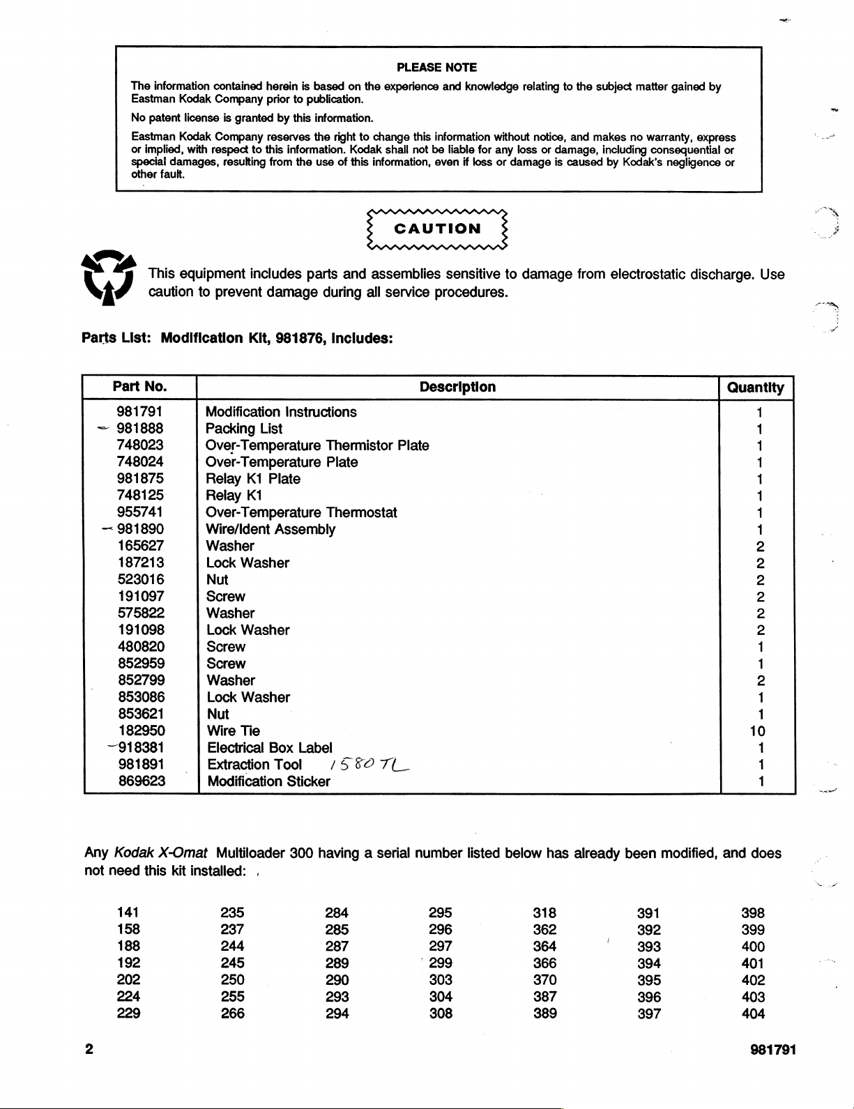
The
information
Eastman
No
patent
Eastman
or
implied,
special
damages,
other
This
caution
List:
No.
165627
187213
523016
191097
575822
191098
480820
852959
852799
853086
182950
918381
fault.
Modification
we
\
J
Parts
Part
—
—
853621
—
981791
981888
748023
748024
981875
748125
955741
981890
981891
869623
contained
Kodak
Company
license
is
Kodak
Company
with
respect
resulting
equipment
to
prevent
Modification
Packing
Over-Temperature
Over-Temperature
Relay
Relay
Over-Temperature
Wire/Ident
Washer
Lock
Nut
Screw
Washer
Lock
Screw
Screw
Washer
Lock
Nut
Wire
Electrical
|
Extraction
Modification
herein
prior
granted
reserves
to
this
from
includes
damage
Kit,
List
K1
Plate
K1
Washer
Washer
Washer
Tie
Box
is
based
to
publication.
by
this
information.
the
information.
981876,
Instructions
Assembly
Too!
Sticker
right
the
use
of
parts
during
Includes:
Thermistor
Plate
Thermostat
Label
/5
on
the
to
change
Kodak
this
information,
and
assemblies
all
|
50°
7(_
PLEASE
experience
this
shall
service
information
not
be
even
procedures.
Description
Plate
NOTE
and
knowledge
if
for
loss
without
any
or
liable
sensitive
relating
notice,
loss
damage
to
damage
or
damage,
is
to
the
and
caused
from
subject
matter
makes
no
including
warranty,
by
consequential
Kodak’s
electrostatic
gained
by
express
negligence
discharge.
or
or
Use
Quantity
4-
=
=
=
==
ANNVNNVNNN=
ANA
AOA
AA
Any
not
Kodak
need
141
158
188
192
202
224
229
X-Omat
this
kit
installed:
Multiloader
,
235
237
244
245
250
255
266
—
300
having a serial
284
285
287
289
290
293
294
number
295
296
297
299
303
304
308
listed
below
318
362
364
366
370
387
389
has
already
been
391
392
393
394
395
396
397
modified,
and
does
398
399
400
401
402
403
404
981791
Page 3
Description
Table
of
Contents
Page
PART A -
PART B -
Electrical
Checking
Deenergizing
Deenergizing
RN
Reversing
Checking
installing
InstallingtheRelayK1....................................
Connecting
Securing
LabelingtheNewiy
installingaWireTleMount............................................
installing
Finishing
Dryer
Installing
Installing
Σε ο αμ
Installing
Bracket
Connecting
Installing
Finishing
Box
Modifications
the
Label
on
Terminal
the
МиНоадег
the
270
RA
A
the
Identification
the
Label
on
Terminal
the
NewRelayKiintothebDryerCircult.................................................
.ee
Block
300...............
TB5...............
иене
Processor...
IA
Tag
on
Terminal
Block
TB4............................................................
Block
TB5
een
the
Relay
Into
the
Dryer
Circuit...
the
Newly
the
New
the
and
Tank
the
Dryer
the
Over-Temperature
the
Over-Temperature
.……… せ ….… せ μμ
Wires
the
New
the
JOD..................oooooooonooooconooccccncccnnonanononononananonnoncconocnnonoconennnononana
Installed
installed
Component
μμ
μμ
Modifications
Over-Temperature
to
the
Developer
Wires.................oooroomoccncccooncnnnonccnnnncanacnnoranannnonocnnnnnnonnnnananancnnonannanccanonsnonos
Wires...................................................
Locator
ο
μμ
ο
Dryer
and
Label...
Thermostat...
Thermostat
Thermostat
ϱϱϱ
μμ
Air
Flow
Switch.........
Fixer
Level
in a Processor
in a Processor
μμ.
sees
Sensing
sneen
nens
Probe
ии
DSE
SELE
ини
ee
With
an
Old
with a New
Se
es
ss
esse
eee
Screws
4
et
5
5
5
6
ns
nn
ини
ee
n
nete
ELLE
teen
ὕωωὕῥυυυς
ss
ss
ss
Type
Dryer
Thermistor
Type
Dryer
Thermistor
NL
een eee
seen
enes
Le
enes
and
Washers..........................
non
ana
nenencnncnnnnnnnnonrnnnnnancnnnananas
НЫ
enes
ans
Kn
sneen
Ken
LEE
nene
sene
И
7
8
9
9
10
12
13
14
15
15
16
17
20
22
26
34
36
981791
3
Page 4
PART
A - Electrical
Box
Modifications
a
λος
981791
Page 5
Checking
the
SECTION
Label
on
Terminal
1
Block
TBS
There
on
is a possibility
incorrectly
TERMINAL
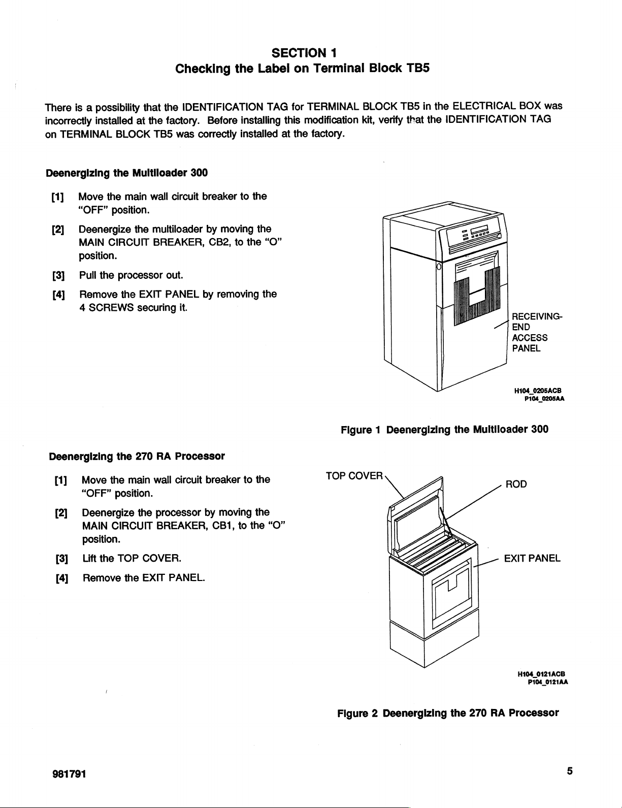
Deenergizing
[1]
[2]
[3]
[4]
installed
Move
“OFF”
Deenergize
MAIN
position.
Pull
the
Remove
4
SCREWS
that
at
BLOCK
the
Multiloader
the
main
position.
the
CIRCUIT
processor
the
EXIT
securing
the
IDENTIFICATION
the
factory.
TB5
was
300
wall
circuit
multiloader
BREAKER,
out.
PANEL
it.
Before
correctly
breaker
by
CB2,
by
installed
to
moving
to
removing
|
TAG
installing
the
the
this
at
the
“O”
the
for
TERMINAL
modification
the
factory.
BLOCK
kit,
verify
R
TB5
that
in
|
the
ELECTRICAL
the
IDENTIFICATION
|
BOX
TAG
RECEIVING-
+
END
ACCESS
PANEL
H104_0205ACB
P104_0205AA
was
Deenergizing
Move
[1]
“OFF"
[2]
Deenergize
MAIN
position.
[3]
Lift
the
[4]
Remove
the
270
the
main
position.
the
CIRCUIT
TOP
COVER.
the
EXIT
RA
Processor
wall
circuit
processor
BREAKER,
PANEL.
breaker
by
moving
CB1,
to
to
the
the
the
“O”
Figure 1 Deenergizing
TOP
COVER
|
Figure 2 Deenergizing
the
Multiloader
_—
the
270
ROD
EXIT
RA
Processor
300
PANEL
H104_0121ACB
P104_0121AA
981791
Page 6
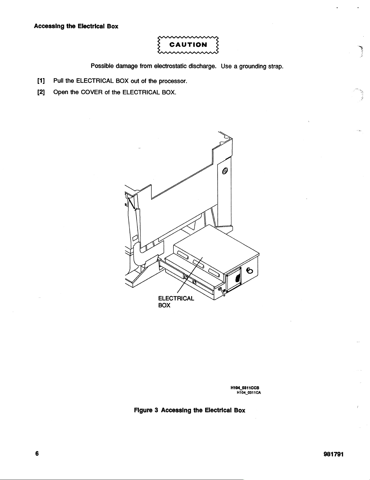
Accessing
the
Electrical
Box
sr
[1]
[2]
Pull
Open
the
ELECTRICAL
the
COVER
Possible
of
the
damage
BOX
out
ELECTRICAL
from
electrostatic
of
the
processor.
BOX.
discharge.
Use a grounding
strap.
Figure 3 Accessing
ELECTRICAL
BOX
the
Electrical
H104
0311CCB
H104_0311CA
Box
6
981791
Page 7
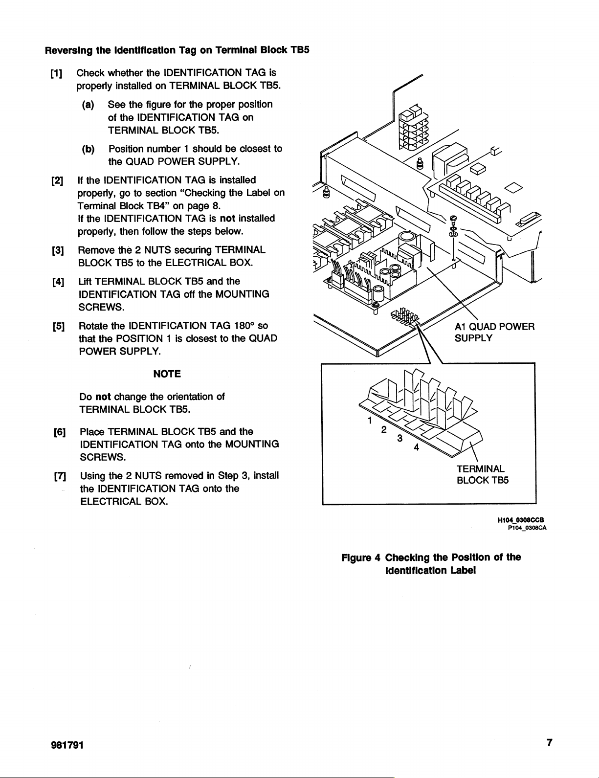
Reversing
the
Identification
Tag
on
Terminal
Block
TB5
Check
[1]
properly
(a)
(b)
If
[2]
[3]
[4]
[5]
the
properly,
Terminal
If
the
properly,
Remove
BLOCK
Lift
IDENTIFICATION
SCREWS.
Rotate
that
POWER
whether
installed
See
of
TERMINAL
Position
the
IDENTIFICATION
IDENTIFICATION
TB5
TERMINAL
the
the
POSITION 1 is
the
the
figure
the
IDENTIFICATION
number 1 should
QUAD
go
to
section
Block
TB4”
then
follow
the 2 NUTS
to
the
BLOCK
IDENTIFICATION
SUPPLY.
IDENTIFICATION
on
TERMINAL
for
the
BLOCK
POWER
ELECTRICAL
TAG
NOTE
TB5.
SUPPLY.
TAG
“Checking
on
page
TAG
the
steps
securing
TB5
off
the
closest
BLOCK
proper
TAG
be
is
installed
the
8.
is
not
below.
TERMINAL
BOX.
and
the
MOUNTING
TAG
180*
to
the
TAG
is
TBS.
position
on
closest
installed
Label
so
QUAD
to
on
A1
QUAD
SUPPLY
POWER
Do
TERMINAL
Place
[6]
IDENTIFICATION
SCREWS.
Using
[7]
the
ELECTRICAL
not
change
TERMINAL
the 2 NUTS
IDENTIFICATION
the
BLOCK
BLOCK
TAG
removed
BOX.
orientation
TBS.
onto
TAG
of
TB5
the
in
onto
and
the
MOUNTING
Step
3,
the
install
Figure 4 Checking
TERMINAL
BLOCK
the
Position
identification
Label
TB5
H104
0308CCB
P104_0308CA
of
the
981791
Page 8
Checking
the
SECTION
Label
on
Terminal
2
Block
TB4
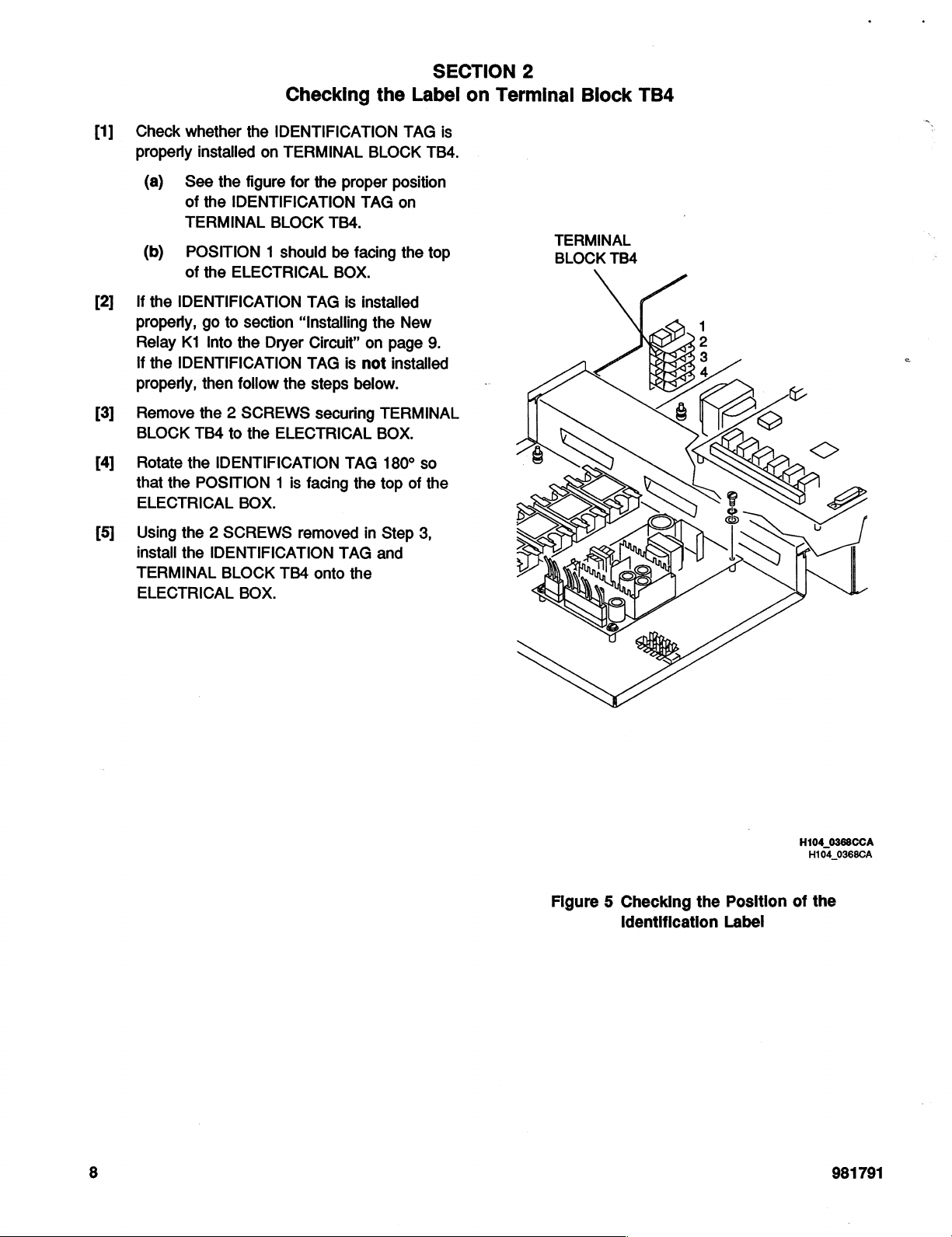
[1]
[2]
[3]
[4]
[5]
Check
properly
If
properly,
Relay
If
properly,
Remove
BLOCK
Rotate
that
ELECTRICAL
Using
install
TERMINAL
ELECTRICAL
whether
installed
(a)
See
of
the
TERMINAL
(b)
POSITION 1 should
of
the
the
IDENTIFICATION
go
K1
Into
the
IDENTIFICATION
then
the 2 SCREWS
TB4
the
the
POSITION 1 is
the 2 SCREWS
the
the
IDENTIFICATION
on
TERMINAL
the
figure
for
the
IDENTIFICATION
BLOCK
ELECTRICAL
TAG
to
section
the
follow
to
the
IDENTIFICATION
BOX.
IDENTIFICATION
BLOCK
BOX.
“Installing
Dryer
Circuit”
TAG
the
steps
ELECTRICAL
facing
removed
TB4
onto
BLOCK
proper
TAG
TB4.
be
facing
BOX.
is
installed
the
on
is
not
below.
securing
TAG
the
in
TAG
the
TAG
TB4.
position
on
the
top
New
page
9.
installed
TERMINAL
BOX.
180°
so
top
of
the
Step
3,
and
is
TERMINAL
BLOCK
TB4
Figure 5 Checking
Identification
the
Position
Label
H104
0368CCA
H104_0368CA
of
the
981791
Page 9
Installing
the
New
SECTION
Relay
K1
3
Into
the
Dryer
Circuit
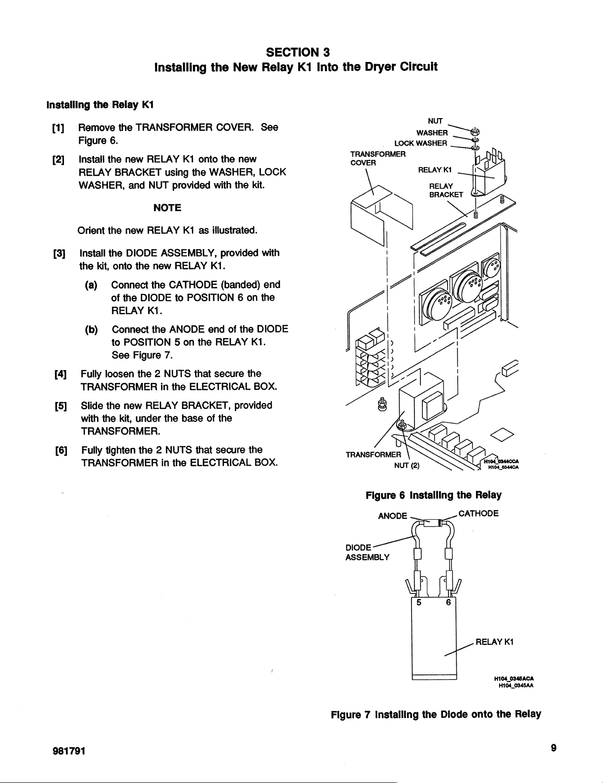
Installing
Remove
[1]
Figure
Install
[2]
RELAY
WASHER,
Orient
Install
[3]
the
(a)
(b)
Fully
[4]
TRANSFORMER
the
kit,
loosen
Relay
6.
the
the
the
onto
Connect
of
RELAY
Connect
to
See
K1
the
TRANSFORMER
new
RELAY
BRACKET
and
NUT
NOTE
new
RELAY
DIODE
the
new
the
the
DIODE
KI.
the
POSITION 5 on
Figure
the 2 NUTS
K1
onto
using
the
provided
K1
as
ASSEMBLY,
RELAY
CATHODE
to
POSITION 6 on
ANODE
the
7.
that
in
the
ELECTRICAL
COVER.
the
new
WASHER,
with
the
kit.
illustrated.
provided
KI.
(banded)
end
of
the
RELAY
secure
KI.
the
See
LOCK
with
end
the
DIODE
BOX.
NUT
LOCK
TRANSFORMER
COVER
C
WASHER
WASHER
RELAY
RELAY
BRACKET
GP
K1
RD
「
|
M
û
[5]
[6]
Slide
with
TRANSFORMER.
the
new
the
kit,
Fully
tighten
TRANSFORMER
RELAY
under
the
the 2 NUTS
in
the
BRACKET,
base
of
the
that
secure
ELECTRICAL
provided
the
BOX.
Figure 6 Installing
ANODE
DIODE
ASSEMBLY
u
5
the
6
AT
Relay
CATHODE
RELAY
K1
H104_0345ACA
H104_0345AA
981791
Figure 7 Installing
the
Diode
onto
the
Relay
Page 10
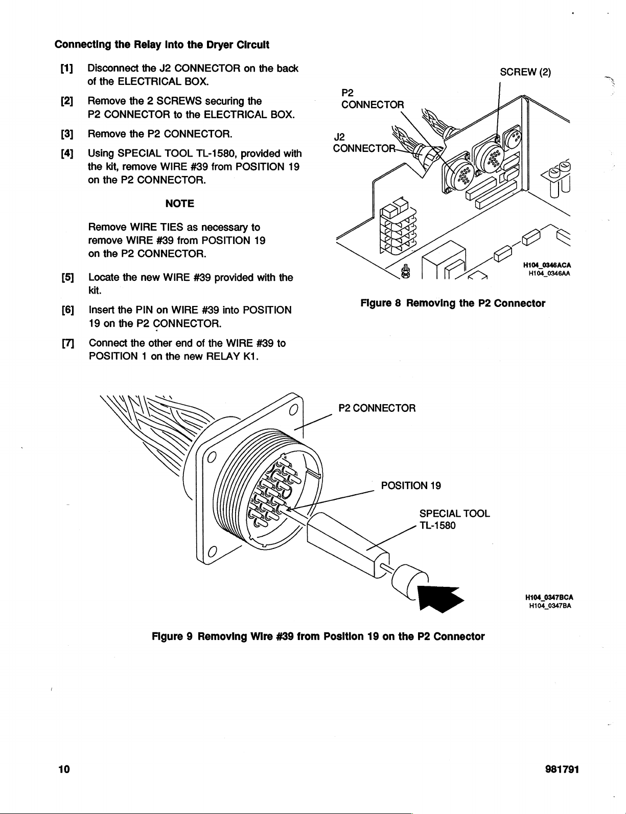
Connecting
the
Relay
Into
the
Dryer
Circult
Disconnect
[1]
of
Remove
[2]
P2
Remove
[3]
Using
[4]
the
on
Remove
remove
on
Locate
[5]
kit,
Insert
[6]
19
Connect
POSITION 1 on
the
ELECTRICAL
the 2 SCREWS
CONNECTOR
the
SPECIAL
kit,
remove
the
P2
CONNECTOR.
WIRE
WIRE
the
P2
CONNECTOR.
the
the
PIN
on
the
P2
the
the
J2
P2
CONNECTOR.
TOOL
WIRE
NOTE
TIES
#39
new
WIRE
on
CONNECTOR.
other
the
CONNECTOR
BOX.
securing
to
the
ELECTRICAL
TL-1580,
#39
as
necessary
from
POSITION
#39
WIRE
#39
end
of
new
from
provided
into
the
WIRE
RELAY
on
the
the
provided
POSITION
to
19
with
POSITION
#39
K1.
back
BOX.
with
the
to
19
P2
CONNECTOR
p
©
Figure 8 Removing
DA
9
の
A
the
P2
SCREW
A
Connector
(2)
ee
s
X
Figure 9 Removing
Wire
#39
from
P2
CONNECTOR
Position
_
POSITION
19
on
(
the
19
SPECIAL
TL-1580
P2
Connector
TOOL
H104_0347BCA
H104_0347BA
10
981791
Page 11
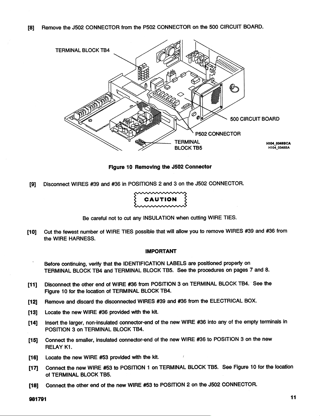
[8]
Remove
the
J502
CONNECTOR
from
the
P502
CONNECTOR
on
the
500
CIRCUIT
BOARD.
[91
TERMINAL
Disconnect
BLOCK
WIRES
#89
TB4
and
Figure
in
#86
10
Removing
POSITIONS
2
the
and
BLOCK
J502
on
3
P502
TB5
Connector
J502
the
500
CONNECTOR
CONNECTOR.
CIRCUIT
BOARD
H104_0348BA
[10]
[11]
[12]
[13]
[14]
[15]
[16]
[17]
the
Cut
|
WIRE
the
Before
TERMINAL
continuing,
Disconnect
Figure
Remove
10
Locate
the
Insert
POSITION
Connect
RELAY
Locate
Connect
of
TERMINAL
fewest
HARNESS.
BLOCK
the
for
and
new
the
larger,
3
smaller,
the
K1.
the
new
the
Be
careful
number
verify
TB4
end
other
location
the
discard
on
new
the
436
WIRE
non-insulated
TERMINAL
insulated
WIRE
WIRE
BLOCK
not
to
TIES
WIRE
of
the
that
TERMINAL
and
WIRE
of
TERMINAL
of
disconnected
provided
connector-end
BLOCK
connector-end
#53
provided
POSITION
to
453
TBS.
cut
any
INSULATION
possible
IDENTIFICATION
from
#36
WIRES
with
TB4.
with
that
IMPORTANT
BLOCK
POSITION
BLOCK
#39
the
kit.
of
of
the
kit.
on
1
when
allow
will
LABELS
See
TB5.
3
TB4.
#36
and
new
the
new
the
TERMINAL
cutting
you
are
the
TERMINAL
on
from
WIRE
WIRE
|
BLOCK
WIRE
remove
to
positioned
procedures
BLOCK
ELECTRICAL
the
any
into
#36
POSITION
to
#36
TB5.
TIES.
WIRES
properly
pages
on
TB4.
the
of
Figure
See
#39
on
BOX.
empty
on
3
and
and
7
See
terminals
the
for
10
#36
8.
the
new
the
from
in
location
[18]
981791
Connect
the
other
end
of
the
new
WIRE
#53
POSITION
to
2
on
the
J502
CONNECTOR.
11
Page 12
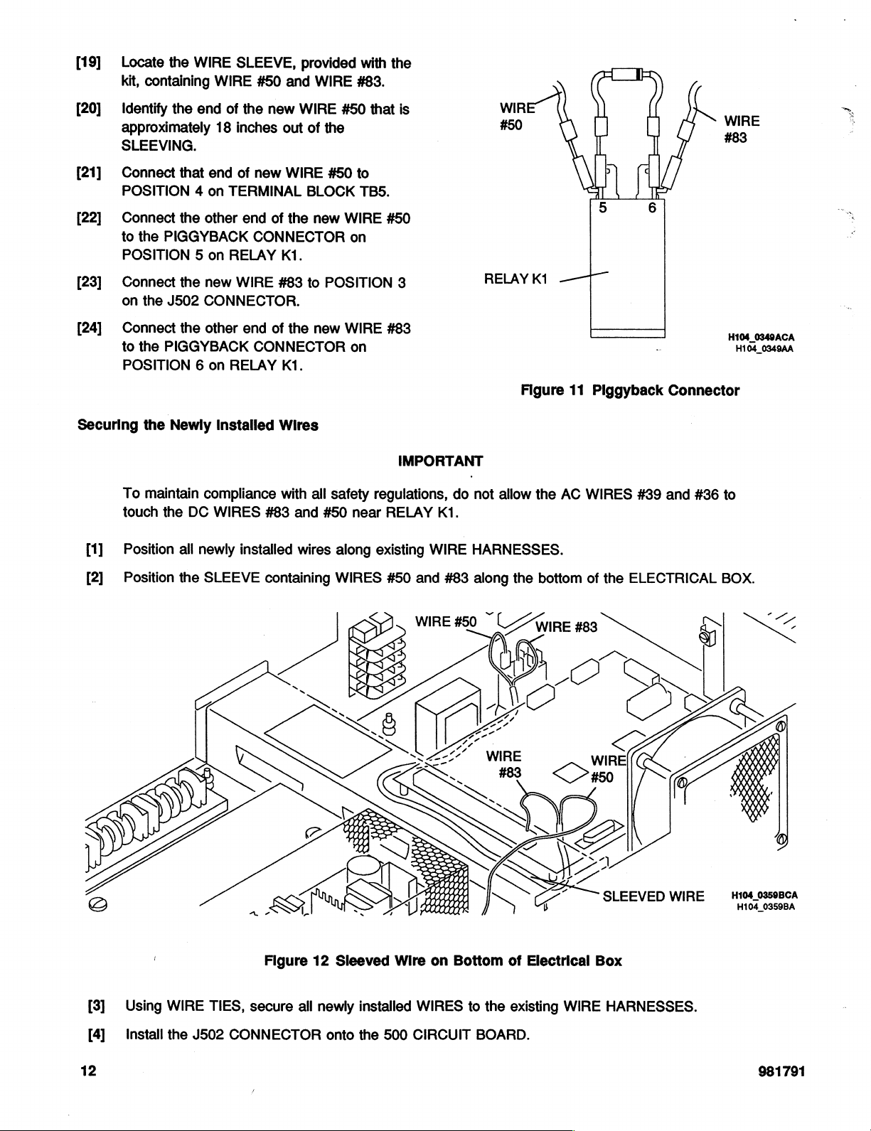
[19]
Locate
kit,
containing
the
WIRE
WIRE
SLEEVE,
#50
provided
and
WIRE
with
#83.
the
[20]
Identify
approximately
SLEEVING.
[21]
[22]
[23]
[24]
Securing
Connect
POSITION
Connect
to
the
POSITION 5 on
Connect
on
the
Connect
to
the
POSITION 6 on
the
To
maintain
touch
the
end
18
end
that
on
4
the
other
PIGGYBACK
the
new
J502
CONNECTOR.
the
other
PIGGYBACK
Newly
the
Installed
compliance
DC
WIRES
of
the
new
inches
new
of
TERMINAL
end
CONNECTOR
RELAY
WIRE
end
CONNECTOR
RELAY
#83
WIRE
out
WIRE
BLOCK
of
the
K1.
483
of
the
KI.
Wires
with
and
#50
of
the
#50
new
WIRE
on
to
POSITION
new
WIRE
on
all
safety
#50
that
is
to
TB5.
#50
3
#83
IMPORTANT
regulations,
near
RELAY
|
do
K1.
WIR
#50
RELAY
not
allow
Ki 一 一
Figure
the
AC
11
Piggyback
WIRES
|
-
#389
WIRE
Connector
and
#86
to
#83
H104
0349ACA
H104_0349AA
[1]
[2]
2
(の
Position
Position
all
newly
the
installed
SLEEVE
wires
containing
|
|
along
WIRES
existing
BES
Figure
12
Sleeved
WIRE
#50
and
WIRE
D
TARA
Wire
on
HARNESSES.
#83
along
#50
Bottom
~
the
A
/
AIA
of
Electrical
bottom
WIRE
of
the
#83
ELECTRICAL
É
Box
BOX.
5
H104_0359BCA
H104
-一
0359BA
[3]
[4]
12
Using
WIRE
Install
the
|
TIES,
J502
secure
CONNECTOR
all
newly
onto
installed
the
500
WIRES
CIRCUIT
to
the
BOARD.
existing
WIRE
HARNESSES.
981791
Page 13

Labeling
[1]
Install
P2
[2]
Install
J502
the
Newly
the
WIRE
CONNECTOR.
the
WIRE
CONNECTOR.
Installed
TIE
labeled
TIE
labeled
Wires
P2,
provided
J502,
with
provided
the
with
kit,
the
onto
kit,
onto
the
the
WIRE
WIRE
HARNESS
HARNESS
leading
leading
to
the
to
the
981791
13
Page 14

SECTION
Installing a Wire
4
Tie
Mount
Some
BOX
Label”
BUNDLES
is
[1]
Install a WIRE
[2]
Using a WIRE
ELECTRICAL
already
procedure
closed.
has a WIRE
on
secured,
TIE
TIE,
BOXES
page
and
MOUNT,
secure
TIE
15.
will
the
have
the
MOUNT
Installing
help
prevent
provided
WIRE
NOTE
WIRE
with
BUNDLE
TIE
installed,
the
WIRE
the
possibility
the
MOUNT
go
kit,
to
the
TIE
to
to
the
newly
already
the
“Installing
MOUNT
of
WIRES
side
of
installed
installed.
the
will
help
being
the
ELECTRICAL
WIRE
If
your
New
Component
keep
the
pinched
TIE
ELECTRICAL
WIRE
when
BOX.
MOUNT.
WIRE
Locator
the
TIE
人
cover
CUT,
MOUNT
Figure
13
Installing
the
Wire
Tie
Mount
to
the
Electrical
Box
14
981791
Page 15

SECTION
5
Some
of
the
TERMINAL
positions.
[1]
Install
proper
(a)
(b)
existing
BLOCK
the
TB5
new
location
Remove
Place
the
LABEL
COMPONENT.
LOCATOR
LABEL
Installing
COMPONENT
as
being
COMPONENT
of
the
new
the
backing
new
COMPONENT
in
the
ELECTRICAL
the
New
LOCATOR
interchanged.
LOCATOR
COMPONENT
from
the
new
LOCATOR
BOX.
Component
LABELS
The
new
LABEL
LOCATOR
COMPONENT
onto
LABEL
show
the
COMPONENT
the
LABEL.
over
Locator
+24
volt
ELECTRICAL
LOCATOR
the
existing
Label
and
the
LOCATOR
BOX.
LABEL.
COMPONENT
24
LABEL
See
volt
return
position
correctly
the
figure
LOCATOR
on
labels
for
the
all
M
[1]
(2)
[3]
[4]
Install
the
page
10.
Install
the
Close
the
Connect
Figure 8 on
the
Figure
P2
CONNECTOR
TRANSFORMER
ELECTRICAL
J2
CONNECTOR
page
10,
14
to
BOX
BOX
if
necessary.
mia,
ER
Installing
Finishing
the
ELECTRICAL
COVER.
COVER.
to
the
P2
New
the
SECTION
the
BOX
CONNECTOR
Component
6
Job
using
on
the
of
Label
the
Locator
the 2 SCREWS
back
removed
ELECTRICAL
in
Step 2 on
/
BOX.
H104_0348BCB
H104_0348BA
See
[5]
981791
Slide
the
ELECTRICAL
BOX
into
the
processor.
15
Page 16

PART B -
Dryer
and
Tank
Modifications
16
981791
Page 17

0]
[2]
Remove:
+
WET
SECTION
è
TOP
EXIT
è
DRYER
è
NON-DRIVE
If
installing
5
WASHERS,
RACK
this
Installing
COVER
ASSEMBLY
SIDE
PANEL
Modification
and 5 LOCK
the
Dryer
(270
RA
Only)
(270
RA
Only).
on a multiloader,
WASHERS.
SECTION
Over-Temperature
remove
1
the
SAFETY
Thermostat
PANEL
by
removing
the 5 SCREWS,
H104_0356DCA
H104_0366DA
981791
Figure
15
Removing
the
Safety
Panel
17
Page 18

There
type
the
old
page
are 2 types
your
processor
type
bracket
22.
of
DRYER
has
and
begin
THERMISTOR
be
sure
on
page
to
20.
IMPORTANT
BRACKETS.
follow
the
The
instructions
Refer
appropriate
for
the
to
the
illustrations
instructions.
new
type
The
bracket
Gea)
>
XY
to
identify
instructions
begin
Old
Type
THERMISTOR
on
the
for
3
Figure
16
Old
Type
Dryer
Thermistor
Bracket
Η104
0142808
P104_0142BA
18
981791
Page 19

|
©
“New
Type
THERMISTOR
BRACKET
Figure
17
New
|
Type
Dryer
H104_0350CCA
Thermistor
H104_0350CA
Bracket
981791
19
Page 20

Installing
[1]
[2]
|
the
Locate
WRAPS,
insert
BLOWER
Over-Temperature
the
remaining 2 WIRES
are
the
WIRES
end
of
MOTOR
the
on
The
#76
WIRE
Thermostat
and
with
the
side
insulated
provided
#86.
the
of
In a Processor
with
insulated
the
processor.
connector
the
kit.
The 2 WIRES,
connector
NOTE
is
the
bigger
With
through
{
——
an
Old
Type
which
the
ACCESS
of
the 2 connectors.
ACCESS
HOLE
Dryer
are
secured
HOLE
Thermistor
together
above
the
Bracket
with
TIE
DRYER
%
+
[3]
Figure
Pull
the
18
WIRES
Inserting
up
through
the
Wires
the
DRYER
through
VT
^
AIR
ング
the
DUCT
~,
DRYER
MOTOR
|
Access
in
the
BLOWER
Hole
bottom
H104_0357ACA
H104_0357AA
Above
of
the
the
Dryer
DRYER
Blower
TANK.
Motor
INSULATED
CONNECTORS
20
Figure
19
Pulling
the
Wires
Up
Through
E
ン
DRYER
the
DRYER
TANK
Dryer
+
Air
AIR
DUCT
Duct
In
the
|
Bottom
of
the
H104_0364BCA
H104_0354BA
Dryer
Tank
981791
Page 21

Using
[4]
LOCK
the
the
THERMOSTAT
kit.
Connect
[5]
the
DRYER
THERMOSTAT.
Remove
[6]
WASHER
THERMISTOR
page
Place
[Π
THERMOSTAT
DRYER
the 2 SCREWS, 2 WASHERS,
WASHERS,
OVER-TEMPERATURE
appropriate
the
DRYER
(a)
(b)
AIR
OVER-TEMPERATURE
the
securing
18.
Save
LOCK
Do
not
THERMISTOR
the
new
THERMISTOR
provided
OVER-TEMPERATURE
BRACKET,
WIRES
SCREW,
the
WASHER
that
DUCT
WASHER,
the
BRACKET.
SCREW,
remove
BRACKET.
OVER-TEMPERATURE
BRACKET
with
THERMOSTAT
provided
you
pulled
in
Step 3 to
DRYER
See
WASHER,
for
reassembly.
the
DRYER
over
BRACKET.
and
the
kit,
with
through
the
and
LOCK
Figure
and
the
existing
2
install
to
the
|
16
on
SCREW 一 和
WASHER
Existing
BRACKET
©
İN
|
|
|
<
v
Neat
TS
|
FI
«————
å
SCREW
4
|
>
LOCK
WASHER
New
BRACKET
OVER-
TEMPERATURE
THERMOSTAT
WASHER
R
THERMOSTAT
E,
GS
|
NK
TS
|
-
之
[8]
[9]
Insert
and
tighten
LOCK
the
BRACKET
BRACKET.
Continue
the
WASHER
OVER-TEMPERATURE
into
with
Dryer
Air
the
removed
the
DRYER
section
Flow
Switch”
SCREW,
“Connecting
WASHER
in
Step 6 through
THERMOSTAT
THERMISTOR
on
page
Wires
26.
and
to
Figure
|
20
Installing
Thermistor
<
an
Old
Bracket
Type
H104
0353CCA
H104_0353CA
Dryer
981791
21
Page 22

Installing
[1]
Remove
(a)
(b)
[2]
Remove
the
Over-Temperature
the
SCREW,
Save
the
Discard
the
and discard
WASHER,
WASHER
SCREW.
the
DRYER
Thermostat
and
and
LOCK
THERMISTOR
In a Processor
LOCK
WASHER
WASHER
for
|
BRACKET.
with a New
securing
Type
the
DRYER
reassembly.
See
Figure
Dryer
Thermistor
THERMISTOR
|
17
on
page
19.
Bracket
BRACKET.
3
[3]
[4]
|
The
INSERT
SCREW,
THERMISTOR
Locate
WRAPS,
Insert
BLOWER
the
the
may
also
come
WASHER,
remaining 2 WIRES
are
WIRES
end
and
BRACKET,
#76
of
the
WIRE
MOTOR.
The
insulated
一 二
LOCK
be
and
with
out
when
WASHER.
sure
provided
#86.
the
connector
一
ι
NOTE
you
remove
When
to
follow
the
with
the
insulated
Φ
connector
NOTE
is
the
the
DRYER
you
are
ready
appropriate
kit.
The 2 WIRES,
through
bigger
of
THERMISTOR
to
install
the
instructions.
which
the
ACCESS
the 2 connectors.
are
BRACKET,
DRYER
secured
HOLE
the
together
above
the
with
TIE
DRYER
LT
Figure
21
Inserting
the
Wires
<=
through
/
the
——
DRYER
MOTOR
|
Access
ACCESS
HOLE
Hole
BLOWER
H104
0357ACA
H104_0357AA
Above
the
Dryer
Blower
Motor
22
981791
Page 23

[5]
Pull
the
WIRES
up
through
the
DRYER
ン
ン
ン
DRYER
ZA
EL
AIR
DUCT
Le.
~
TANK
in
the
DRYER
bottom
AIR
DUCT
of
the
DRYER
|
C
TANK.
INSULATED
CONNECTORS
”
H104_0354BCA
H104_0354BA
Figure
[6]
Using
the 2 SCREWS, 2 WASHERS,
OVER-TEMPERATURE
the
kit.
[7]
Connect
OVER-TEMPERATURE
22
Pulling
the
WIRES
the
Wires
THERMOSTAT
that
you
THERMOSTAT.
Up
Through
pulled
the
and 2 LOCK
to
the
through
the
Dryer
Alr
Duct
In
the
WASHERS,
THERMISTOR/THERMOSTAT
DRYER
AIR
provided
DUCT
Bottom
with
in
Step 5 to
of
the
the
kit,
BRACKET,
the
Dryer
install
the
provided
DRYER
Tank
with
981791
23
Page 24

[8]
Place
the
new
THERMISTOR/THERMOSTAT
WASHER
$
ad
BRACKET
SCREW
LOCK
over
WASHER
the
DRYER
THERMISTOR.
OVER-
TEMPERATURE|
THERMOSTAT
©
NS
P<
+、
THERMISTOR/
THERMOSTAT
BRAckET
| ャ ーー
WASHER
LOCK
WASHER
Figure
23
Installing a New
Type
Dryer
Thermistor/Thermostat
H104
0351CCA
H104_0351CA
Bracket
24
981791
Page 25

If
the
INSERT
you
removed
BRACKET,
[1]
[2]
[5]
remained
the
DRYER
follow
Insert
the
new
and
the
WASHER
removed
THERMISTOR/THERMOSTAT
Tighten
Using a SCREWDRIVER,
1/4
turn
in
Step 6 on
the
SCREW
and
In
the
Instructions
SCREW,
and
no
more.
the
THERMISTOR
only
processor
provided
LOCK
page
21
finger
tighten
below:
with
WASHER
into
the
BRACKET.
tight.
the
when
the
SCREW
kit,
WASHER
THERMISTOR
©
<!
No,
er
o
k
NED
|
|
HT
<
一
NUT
|
ーーーーー-
ゅ
<
テーーーー
LOCK
WASHER
THERMISTOR/
THERMOSTAT
BRACKET
OVER-TEMPERATURE
THERMOSTAT
WASHER
WASHER
LOCK
一
-一
SCREW
TS
asso
my,
If
the
INSERT
you
removed
BRACKET,
Position
[1]
WIRES
when
the
Use
THERMISTOR/THERMOSTAT
Using
[2]
3/16
through
INSERT
Thoroughly
[3]
remove
came
the
follow
the
so
you
TANK.
care
an
in.
DRILL
the
all
out
of
the
processor
DRYER
the
THERMISTOR/THERMOSTAT
that
drill
to
not
ELECTRIC
bottom
was
clean
the
THERMISTOR
Instructions
they
will
the
hole
through
drill
through
DRILL,
BIT,
TL-9212,
of
the
located.
the
DRYER
shavings.
not
TANK
be
when
below:
in
the
way
the
bottom
the
WIRES.
TL-1466,
make a hole
AIR
where
DUCT
with
the
of
to
a
Sle
DRILLED
HOLE
| |
|
ἆ
H104
0352CCA
H104_0352CA
[4]
[5]
981791
Install
the
through
Install
the
NUT,
provided
SCREW
SCREW,
the
newly
WASHER,
with
installed
provided
created
LOCK
the
kit,
in
the
previous
with
hole.
WASHER,
to
secure
the
kit,
the
step.
Up
and
Figure
24
Replacing
Hardware
the
Insert
Provided
with
the
25
Page 26

Connecting
[1]
Remove
removing
LOCK
6
If
removing
COVER
need
WASHERS,
Wires
to
to
the
Dryer
the
DRYER
the
6
WASHERS
the
from a multiloader,
remove
and
IMPORTANT
PLENUM
SCREWS,
securing
NOTE
DRYER
only 4 SCREWS,
LOCK
Alr
Flow
COVER
6
WASHERS,
it.
PLENUM
you
WASHERS.
Switch
by
and
will
There
AIR
paddle-like
the
FLOW
protrusion
Refer
type
to
The
Old
page
connecting
Switch
are 2 types
FLOW
SWITCHES.
FLOW
SWITCH.
SWITCH
to
your
follow
instructions
Type
28.
begin
extending
the
processor
the
Air
The
of
DRYER
The
SWITCH
protrusion
illustrations
appropriate
Flow
to
the
on
has a flat,
extending
The
New
has
a
bent,
from
has
for
connecting
Switch
instructions
New
Type
page
31.
AIR
Old
Type
from
Type
AIR
arm-like
the
SWITCH.
to
identify
and
instructions.
begin
for
be
to
Air
the
sure
the
on
Flow
Old
Type
AIR
FLOW
SWITCH
26
H104_0146CCB
P104
0146CA
Figure
|
25
Old
Type
Dryer
Alr
Flow
Switch
981791
Page 27

New
AIR
SWITCH
Type
FLOW
981791
Figure
26
New
Type
Alr
Flow
H104_0355CCA
H104_0355CA
Switch
27
Page 28

Connecting
In
this
section
the
DRYER
The
DRYER
temperature
Wires
AIR
OVER-TEMPERATURE
exceeds a safe
to
of
the
modification,
VANE
an
Old
SWITCH.
Type
you
This
level.
Dryer
Air
will
be
will
protect
THERMOSTAT
Flow
wiring
the
Switch
the
OVER-TEMPERATURE
processor
will
tum
off
if
the
the
DRYER
DRYER
THERMOSTAT
HEATER
HEATER
if
circuit
malfunctions.
the
DRYER
in
series
with
—
[1]
Remove
[2]
If
you
If
you
Using a small
ES
Figure
the
have a Multiloader
have a 270
27
CONNECTOR
SCREW
Wiring
RA
DRIVER,
y
>>
the
HOUSING
300,
remove
Processor,
press
Over-Temperature
from
the
DRYER
WIRE
remove
the
WIRE
CLIP
#50
#53
NOTE
inside
Thermostat
AIR
from
the
from
the
CONNECTOR
oa
to
FLOW
CONNECTOR
the
CONNECTOR
the
Alr
SWITCH.
HOUSING.
HOUSING
Flow
Switch
HOUSING.
to
release
H104_0370BC
the
WIRE.
28
WIRE
#50/#53
CONNECTOR
Figure
HOUSING
28
Removing
Wire
#50/#53
from
the
Connector
Housing
H104_0314BCB
H104_0314BA
981791
Page 29

[3]
Insert
either
HOUSING.
of
the 2 WIRES
Press
the
WIRE
from
the
CONNECTOR
OVER-TEMPERATURE
completely
into
the
THERMOSTAT
CONNECTOR
into
the
HOUSING.
CONNECTOR
[4]
[5]
[6]
DES
Connect
Using
SPLICE
SPLICE
the
Using
SPLICE
PLIERS,
PLIERS,
the
CONNECTOR
connect
CONNECTOR,
CONNECTOR.
connect
CONNECTOR.
SK
HOUSING
the
remaining
provided
the
wire
Verify
to
the
DRYER
wire
from
with
the
kit.
removed
that
the
in
wire
Step 2 on
SPLICE
CONNECTOR
AIR
the
OVER-TEMPERATURE
Verify
that
page
is
completely
FLOW
the
SWITCH.
wire
is
28
(WIRE
connected
completely
THERMOSTAT
#50
or
to
the
N
connected
#53)
to
SPLICE
to
to
the
other
CONNECTOR.
NF
the
new
the
end
of
H104_0358BCA
H104_0358BA
Figure
Verify
that
29
Connecting
the
SPLICE
the
Wires
CONNECTOR
to
the
IMPORTANT
is
outside
Over-Temperature
of
the
DRYER
Thermostat
PLENUM
COVER.
981791
29
Page 30

[7]
Install
the
DRYER
PLENUM
COVER.
[8]
[9]
[10]
Position
WIRE
Verify
positioned
DRYER
will
Install
PANEL
have.
Go
the
TIES,
that
PLENUM
not
be
the
depending
to
Step 1 on
all
in
pinched.
SAFETY
wires
and
if
necessary.
NOTE
the
wires
the
GROOVE
COVER
PANEL
on
page
secure
are
See
which
34.
the
properly
on
the
so
that
the
figure.
or
the
equipment
wires
they
SIDE
with
you
GROOVE
DRYER
PLENUM
COVER
Figure
30
Routing
Groove
Wires
In
the
H104_0356CCA
Through
Dryer
Plenum
H104_0356CA
the
30
981791
Page 31

Connecting
In
this
section
the
DRYER
The
DRYER
temperature
Wires
AIR
exceeds a safe
to a New
of
the
modification,
VANE
OVER-TEMPERATURE
SWITCH.
Type
you
This
level.
Dryer
Alr
will
be
will
protect
THERMOSTAT
Flow
wiring
Switch
the
OVER-TEMPERATURE
the
processor
will
turn
off
if
the
the
DRYER
DRYER
THERMOSTAT
HEATER
HEATER
circuit
if
the
in
series
malfunctions.
DRYER
with
——a
[1]
Locate
[2]
If
If
>
Figure
the
AIR
FLOW
you
have a Multiloader
you
have a 270
31
RA
Wiring
the
Over-Temperature
SWITCH
300,
Processor,
CONNECTORS
disconnect
WIRE
disconnect
#50
WIRE
Thermostat
in
the
DRYER
from
#53
from
the
to
PLENUM.
AIR
the
AIR
the
FLOW
FLOW
Alr
SWITCH
Flow
SWITCH
a
H104_0369BC
Switch
CONNECTOR.
CONNECTOR.
981791
31
Page 32

[3]
[4]
Using
PLIERS,
Verify
that
Install
either
CONNECTOR,
the
one
connect
wire
is
of
the
provided
WIRE
#50
completely
wires
from
with
the
or
#53
to
connected
the
THERMOSTAT
kit.
the
to
new
the
SPLICE
SPLICE
to
CONNECTOR,
CONNECTOR.
the
other
end
of
provided
the
new
with
SPLICE
the
kit.
NO
A
Figure
32
Installing
SPLICE
CONNECTOR
the
Splice
Connector
to
the
Thermostat
|
δ-/
3
S
|
9
Wire
OA
H104
H104_0358BA
0358BCA
32
981791
Page 33

[5]
Locate
THERMOSTAT.
the
second
wire
from
the
Connect
[6]
the
disconnected
Install
[7]
Position
[8]
WIRE
Verify
positioned
DRYER
will
Install
[9]
PANEL
have.
AIR
FLOW
the
TIES,
that
not
be
the
depending
that
second
in
DRYER
the
wires
if
necessary.
all
the
in
the
PLENUM
pinched.
SAFETY
THERMOSTAT
SWITCH
Step 2 on
PLENUM
and
secure
NOTE
wires
GROOVE
COVER
See
PANEL
on
which
CONNECTOR
page
COVER.
the
are
properly
on
the
so
that
the
figure.
or
the
equipment
31.
wires
they
SIDE
wire
with
you
to
GROOVE
DRYER
PLENUM
COVER
Figure
33
Installing
the
Dryer
Plenum
H104
H104
Cover
0356CCA
0356CA
981791
33
Page 34

In
this
procedure
from
leaking
eliminate
eliminate
[1]
the
the
Remove
you
through
problem
poor
electrical
and
will
seal
the
tank
of
deposits
discard
Installing
Level
contact
the
the
screw
walls
forming
LEVEL
Sensing
onto
and
SECTION
the
New
Probe
holes
in
the
the
LEVEL
on
the
LEVEL
the
malfunctioning
SENSING
PROBE
Developer
Screws
Fixer
and
SENSING
SENSING
of
SCREW
NOTE
2
and
and
Washers
Developer Tank
PROBE
the
SCREWS.
PROBE
LEVEL
on
the
SENSING
Fixer
side
SCREWS,
side
wall
walls
to
This
procedure
and
PROBES.
of
the
prevent
should
therefore
DEVELOPER
chemistry
should
TANK.
-
№
Some
wall
DEVELOPER
SENSING
[2]
Position
the
[3]
Using
CONNECTOR/WIRE
[4]
Repeat
of
of
the
hole
the
the
later
DEVELOPER
PROBE.
the
new
in
the
new
the
procedure
model
TANK,
WASHER,
side
SCREW,
processors
remove
wall
of
provided
to
the
for
TANK.
the
provided
the
side
the
LEVEL
have 2 LEVEL
If
your
processor
SCREW
with
DEVELOPER
with
the
wall
of
the
SENSING
that
secures
the
kit,
TANK.
kit,
secure
DEVELOPER
PROBE
SENSING
has 2 SCREWS
the
CONNECTOR/WIRE
so
that
the
See
Figure
the
LEVEL
TANK.
SCREW
PROBE
GASKET
34
SENSING
in
SCREWS
through
side
on
page
the
side
the
side
of
the
35.
PROBE
wall
through
wall
to
the
WASHER
and
of
the
the
of
the
LEVEL
the
FIXER
side
is
against
TANK.
^
:
34
|
|
981791
Page 35

WASHER
x
SCREW
GASKET
A
À
CONNECTOR/
WIRE
AZ
Figure
34
installing
the
New
Washer
and
Level
Sensing
Probe
Screw
H104_0867DCA
H104
0367DA
|
981791
35
Page 36

SECTION
3
[1]
[2]
install:
*
DRYER
.
ТОР
.
МЕТ
Circle
*
For a Multiloader
*
For a 270
RACK
EXIT
ASSEMBLY
SECTION
the
appropriate
RA
COVER.
number
300,
circle
Processor,
(270
RA
on
number
circle
Finishing
the
Only)
the
Modification
11.
number
8.
Sticker.
MODIFICATION
STICKER
Job
レン
MODIFICATION
STICKER
TS,
ON
_
Figure
[3]
[4]
[5]
[6]
[8]
35
If
you
Install
Close
Energize
Move
Verify
Locating
on a Multiloader
have a multiloader,
the
EXIT
PANEL.
the
TOP
COVER.
the
unit
the
main
wall
proper
operation
the
Modification
300
by
moving
circuit
of
slide
the
the
breaker
the
processor.
H104
H104_0343AC
Sticker
processor
MAIN
CIRCUIT
to
the
0343ACA
“ON”
back
into
BREAKER
position.
Figure
the
|
36
multiloader.
to
the
Locating
on a 270
“I”
position.
ーー
で
レプ
the
Modification
RA
Processor
DRYER
PLENUM
H104
0336ACA
H104
Sticker
0336AA
981791
Page 37

[9]
Locate
the
Diagrams
The
Modification
appropriate
that
do
not
Kit
set
of
new
Wiring
apply
to
your
includes 2 sets
Diagrams,
equipment.
of
new
Wiring
NOTE
provided
Diagrams
with
the
that
illustrate
kit.
Discard
the
new
the
set
of
circuits:
new
Wiring
[10]
* a set
* a set
Insert
*
*
for
for
the
Publication
Publication
the
the
new
Kodak
Kodak
pages
Number
Number
X-Omat
X-Omat
into
their
WD
3058-1
636720
Multiloader
270
RA
Processor
proper
for
for
the
places
the
Kodak
300
in
Kodak
X-Omat
your
X-Omat
Wiring
Multiloader
270
RA
Diagram
Processor.
Package.
300
981791
37
Page 38

22
3058mi_11.bxt
Kodak
EASTMAN
and
X-Omat
KODAK
are
trademarks.
Customer
COMPANY
Equipment
+
ROCHESTER,
Services
N.Y.
Division
14650
Printed
in
USA
 Loading...