

Page 1
{ServiceManual}{Production}{He althImaging}
Publication No. 7C8772
12JAN99
HEALTH IMAGING
SERVICE MANUAL
Kodak X-Omat
Service Code: 3554
Kodak X-Omat
Service Code: 3555
for the
2000 PROCESSOR
and the
2000A PROCESSOR
© Eastman Kodak Company, 1999
Page 2

PLEASE NOTE The information contained herein is based on the experience and knowledge relating to the
subject matter gained by Eastman Kodak Company prior to publication.
No patent license is granted by this information.
Eastman Kodak Company reserves the right to change this information without notice, and
makes no warranty, express or implied, with respect to this information. Kodak shall not be liable
for any loss or damage, including consequential or special damages, resulting from any use of
this information, even if loss or damage is caused by Kodak’s negligence or other fault.
Warning
To avoid hazardous conditions, keep floors and floor coverings around your
associated drains clean and dry at all times. Any accumulation of fluids from mixing tanks, drain lines, etc., should
be cleaned up immediately. In the event of an accumulation of liquid due to backup, overflow, orother malfunctions
of the drain associated with your
the drain. Kodak accepts no responsibility or liability whatsoever for the serviceability of any drain connected to or
associated with a
Radio Interference
Kodak X-Omat
X-Omat
Processor. Such drains are the sole responsibility of the customer.
Processor, call a plumber or other contractor to correct any problem with
Kodak X-Omat
Processor and
Caution
This equipment generates,uses, and canradiate radio-frequency energy.If the equipment is not installed and used
according to the instructions, it may cause interference to radio communications. The equipment has been tested
and found to comply with the limits for a
which are designedto provide reasonable protection against such interferencewhen the equipment is operated in a
commercial environment. Operation of this equipment in a residential area is likely to cause interference, in which
case the user at the user's own expense will be required to take whatever measures may be required to correct the
interference.
This digital apparatus does not exceed the
the Radio Interference Regulations of the Canadian Department of Communications.
Class A
Class A
computing device pursuant to Subpart J of Part 15 of the FCC Rules,
limits for radio noise emissions from digital apparatus set out in
Table of Contents
Description Page
Overview . . . . . . . . . . . . . . . . . . . . . . . . . . . . . . . . . . . . . . . . . . . . . . . . . . . . . . . . . . . . . . 4
Feed End . . . . . . . . . . . . . . . . . . . . . . . . . . . . . . . . . . . . . . . . . . . . . . . . . . . . . . . . . . 6
Receiving End . . . . . . . . . . . . . . . . . . . . . . . . . . . . . . . . . . . . . . . . . . . . . . . . . . . . . . 8
ROLLER Transport System . . . . . . . . . . . . . . . . . . . . . . . . . . . . . . . . . . . . . . . . . . . . . . . 11
DETECTOR CROSSOVER - Drive Side . . . . . . . . . . . . . . . . . . . . . . . . . . . . . . . . . . 12
DETECTOR CROSSOVER - Non-Drive Side . . . . . . . . . . . . . . . . . . . . . . . . . . . . . . 14
DEVELOPER/FIXER CROSSOVER AY - Drive Side. . . . . . . . . . . . . . . . . . . . . . . . 18
DEVELOPER/FIXER CROSSOVER AY - Non-Drive Side . . . . . . . . . . . . . . . . . . . . 20
FIXER/WASH CROSSOVER AY - Drive Side . . . . . . . . . . . . . . . . . . . . . . . . . . . . . . 22
FIXER/WASH CROSSOVER AY - Non-Drive Side . . . . . . . . . . . . . . . . . . . . . . . . . . 24
DEVELOPER and FIXER RACKS - Top EXIT ROLLERS. . . . . . . . . . . . . . . . . . . . . 26
WASH RACK - Top EXIT ROLLERS . . . . . . . . . . . . . . . . . . . . . . . . . . . . . . . . . . . . . 28
DEVELOPER and WASH RACKS - Other ROLLERS. . . . . . . . . . . . . . . . . . . . . . . . 30
FIXER RACK - Other ROLLERS . . . . . . . . . . . . . . . . . . . . . . . . . . . . . . . . . . . . . . . . 32
TURNAROUND ASSEMBLIES . . . . . . . . . . . . . . . . . . . . . . . . . . . . . . . . . . . . . . . . . 34
DRYER RACK - FRAME . . . . . . . . . . . . . . . . . . . . . . . . . . . . . . . . . . . . . . . . . . . . . . 38
DRYER RACK - ROLLERS . . . . . . . . . . . . . . . . . . . . . . . . . . . . . . . . . . . . . . . . . . . . 40
DRYER RACK - Miscellaneous Parts . . . . . . . . . . . . . . . . . . . . . . . . . . . . . . . . . . . . 42
MAIN DRIVE ASSEMBLY . . . . . . . . . . . . . . . . . . . . . . . . . . . . . . . . . . . . . . . . . . . . . . . . . 44
MAIN DRIVE SHAFT and MOTOR . . . . . . . . . . . . . . . . . . . . . . . . . . . . . . . . . . . . . . 44
2 12JAN99 – 7C8772
Page 3

BLOWER ASSEMBLY . . . . . . . . . . . . . . . . . . . . . . . . . . . . . . . . . . . . . . . . . . . . . . . . . . . . 46
BLOWER ASSEMBLY . . . . . . . . . . . . . . . . . . . . . . . . . . . . . . . . . . . . . . . . . . . . . . . . 46
Plumbing . . . . . . . . . . . . . . . . . . . . . . . . . . . . . . . . . . . . . . . . . . . . . . . . . . . . . . . . . . . . . . 48
Developer Plumbing Circulation . . . . . . . . . . . . . . . . . . . . . . . . . . . . . . . . . . . . . . . . . 48
Fixer and Wash Plumbing Circulation. . . . . . . . . . . . . . . . . . . . . . . . . . . . . . . . . . . . . 50
DEVELOPER THERMOWELL AY . . . . . . . . . . . . . . . . . . . . . . . . . . . . . . . . . . . . . . . 52
HEAT EXCHANGERS . . . . . . . . . . . . . . . . . . . . . . . . . . . . . . . . . . . . . . . . . . . . . . . . 54
RECIRCULATION PUMP. . . . . . . . . . . . . . . . . . . . . . . . . . . . . . . . . . . . . . . . . . . . . . 56
REPLENISHMENT PUMP . . . . . . . . . . . . . . . . . . . . . . . . . . . . . . . . . . . . . . . . . . . . . 58
WEIRS . . . . . . . . . . . . . . . . . . . . . . . . . . . . . . . . . . . . . . . . . . . . . . . . . . . . . . . . . . . . 60
Electrical . . . . . . . . . . . . . . . . . . . . . . . . . . . . . . . . . . . . . . . . . . . . . . . . . . . . . . . . . . . . . . 61
SWITCHES, SAFELIGHT RECEPTACLE, and CIRCUIT BREAKER . . . . . . . . . . . . 61
ELECTRICAL BOX. . . . . . . . . . . . . . . . . . . . . . . . . . . . . . . . . . . . . . . . . . . . . . . . . . . 62
Miscellaneous Parts and Accessories . . . . . . . . . . . . . . . . . . . . . . . . . . . . . . . . . . . . . . . . 65
Miscellaneous Parts . . . . . . . . . . . . . . . . . . . . . . . . . . . . . . . . . . . . . . . . . . . . . . . . . . 66
Accessories . . . . . . . . . . . . . . . . . . . . . . . . . . . . . . . . . . . . . . . . . . . . . . . . . . . . . . . . 68
POWER CORD and WALL RECEPTACLE . . . . . . . . . . . . . . . . . . . . . . . . . . . . . . . . 70
REPLENISHMENT TANK KITS . . . . . . . . . . . . . . . . . . . . . . . . . . . . . . . . . . . . . . . . . 71
SEISMIC BRACKET. . . . . . . . . . . . . . . . . . . . . . . . . . . . . . . . . . . . . . . . . . . . . . . . . . 72
Alphabetical Index . . . . . . . . . . . . . . . . . . . . . . . . . . . . . . . . . . . . . . . . . . . . . . . . . . . . . . . 73
Numerical Index . . . . . . . . . . . . . . . . . . . . . . . . . . . . . . . . . . . . . . . . . . . . . . . . . . . . . . . . . 83
Publication History . . . . . . . . . . . . . . . . . . . . . . . . . . . . . . . . . . . . . . . . . . . . . . . . . . . . . . . 93
7C8772 – 12JAN99 3
Page 4

SERVICE MANUAL
Section 1: Introduction
Electrostatic Discharge
ESD - Electrostatic discharge - is a primary source of:
• product downtime
• low productivity
• costly repairs
While one cannot feel a static charge of less than 3,500 volts, as few as 30 volts can damage or destroy essential
components in electronic equipment.
Preventive Measures
• Always look for an ESD warning labelbeforedoingany procedure involving static-sensitive components such as
CIRCUIT BOARDS. All static-sensitive components are marked with bright graphic labels which frequently
include instructions. Follow all label instructions.
• WearaGROUNDINGSTRAPwhenhandlingstatic-sensitive components. Always be surethattheCLIPremains
attached to a properly grounded, unpainted, clean surface.
• Repair static-sensitive componentsat an ESD-protected workstation or usea portable GROUNDING MAT.For
help in setting up an ESD-protected work station, contact your Kodak representative.
• When moving static-sensitive components from one area to another, insert and transport the components in
ESD-protective packaging.
Special Tools
• SEALANT TL-3230
• MOTOR OIL, 1 oz TUBE TL-2244
• MOTOR OIL, 12 oz TUBE TL-2324
• POTENTIOMETER ADJUSTING TOOL TL-1481
• THERMOMETER 716217
4 12JAN99 – 7C8772
Page 5
Section 2: Adjustments and Replacements
FEED SHELF
Adjustment
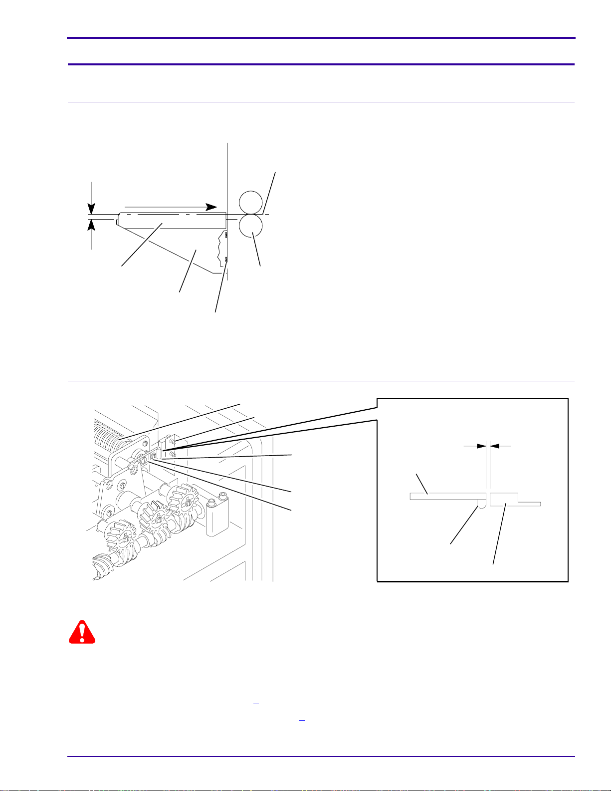
[1] Loosen the 4 SCREWS.
[2] Adjust the height of the FEED SHELF to 1.5 mm
1.5 mm
(0.06 in.)
NIP
film entry path
(1⁄16 in.) below the NIP of the DETECTOR
CROSSOVER ROLLERS.
[3] Insert a 35 x 43 cm sheet of film into the NIPofthe
DETECTOR CROSSOVER ROLLERS.
[4] To adjust forsquareness, use the film to align the
FILM GUIDE with theDETECTOR CROSSOVER
ROLLERS.
[5] Tighten the 4 SCREWS.
Adjustments and Replacements
FILM
GUIDE
FEED
SHELF
H172_1017ACA
H172_1017AC
DETECTOR SWITCH
Adjustment
DETECTOR
CROSSOVER
ROLLERS
SCREW (4)
DETECTOR ROLLER
2 SCREWS
2 DETECTOR
SWITCHES
SCREW
ROCKER ARM
1.6 mm
(0.06 in.)
ROCKER
ARM
2 MAGNETS
2 DETECTOR SWITCHES
H172_1036BCA
H172_1036BA
Warning
Moving Parts
[1] Remove the TOP COVER.
[2] Check for squareness:
• DEVELOPER RACK, See Page 9
• DETECTOR CROSSOVER AY, See Page 7
[3] Install:
7C8772 – 12JAN99 5
Page 6

SERVICE MANUAL
• DEVELOPER RACK
• DETECTOR CROSSOVER AY
[4] Loosen the 2 SCREWS on the DETECTOR SWITCHES.
[5] Move the 2 DETECTOR SWITCHES up to the top position.
[6] Set the distance between the MAGNET and the DETECTOR SWITCH on the drive side to 1.6 mm (0.06 in.):
(a) Loosen the SCREW.
(b) Move the ROCKER ARM.
(c) Tighten the SCREW.
Warning
Dangerous Voltage
[7] Energize the PROCESSOR.
[8] Lift the top DETECTOR ROLLER.
[9] Insert a 2.54 cm (1 in.) piece of film into the drive side of the DETECTOR ROLLER.
[10] Slowly move the DETECTOR SWITCH on the drive side down until the REPLENISHMENT PUMP actuates.
[11] Tighten the 2 SCREWS on the DETECTOR SWITCH.
[12] Check that the REPLENISHMENT PUMP stops in 3 seconds after you remove the film.
Note
The feed signal will emit a beep.
[13] Repeat Steps 8-12 for the DETECTOR SWITCH on the non-drive side.
[14] Install the TOP COVER.
[15] Check that the REPLENISHMENT PUMP does not operate unless you feed film.
Replacement
2 LOCK WASHERS
2 SCREWS
DETECTOR
SWITCH
2 WASHERS
H172_1037BCA
H172_1037BA
Warning
Dangerous Voltage
[1] Disconnect the PROCESSOR from the main power.
[2] Remove:
• TOP COVER
• 2 SCREWS
6 12JAN99 – 7C8772
Page 7
• 2 LOCK WASHERS
• 2 WASHERS
• DETECTOR SWITCHES
• WIRE TIES, not visible in graphic
ESD
Possible damage from electrostatic discharge.
[3] Disconnect the SWITCH CABLE from the ELECTRICAL BOX.
[4] Connect the new SWITCH CABLE to the ELECTRICAL BOX.
[5] Install:
• DETECTOR SWITCHES
• 2 WASHERS
• 2 LOCK WASHERS
• 2 SCREWS
• new WIRE TIES
• TOP COVER
Adjustments and Replacements
Warning
Dangerous Voltage
[6] Connect the PROCESSOR to the main power.
[7] Do the adjustment procedure for the DETECTOR SWITCHES. See Page 5.
CROSSOVER AY
Adjustment for Squareness
[1] Remove the CROSSOVER AY from the PROCESSOR.
[2] Place the CROSSOVER AY on a smooth, flat surface with the GUIDE SHOES up.
TIE ROD
SIDE
PLATE
2 GUIDE SHOE
SCREWS
TIE ROD
LONG TIP
NUT
SIDE PLATE
NUT
H172_1038BCA
H172_1038BA
[3] Loosen the 4 NUTS on the TIE RODS.
[4] Press down on the SIDE PLATES so that the SIDE PLATES make uniform contact with the flat surface.
[5] Tighten the 4 NUTS.
7C8772 – 12JAN99 7
Page 8
SERVICE MANUAL
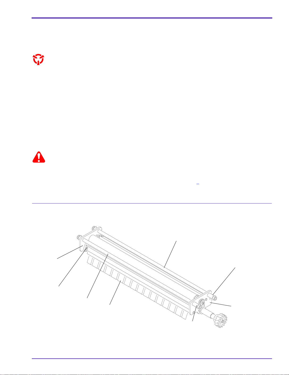
Installing a new GUIDE SHOE
GUIDE SHOE
[1] Remove:
• SCREWS
• GUIDE SHOE
[2] InstallthenewGUIDE SHOE with theLONGTIPS
in the direction of film transport.
[3] Install the SCREWS.
Note
There are no adjustment procedures for GUIDE
SHOES.
LONG
TIP
SHORT
TIP
H172_1045CCA
H172_1045CA
8 12JAN99 – 7C8772
Page 9
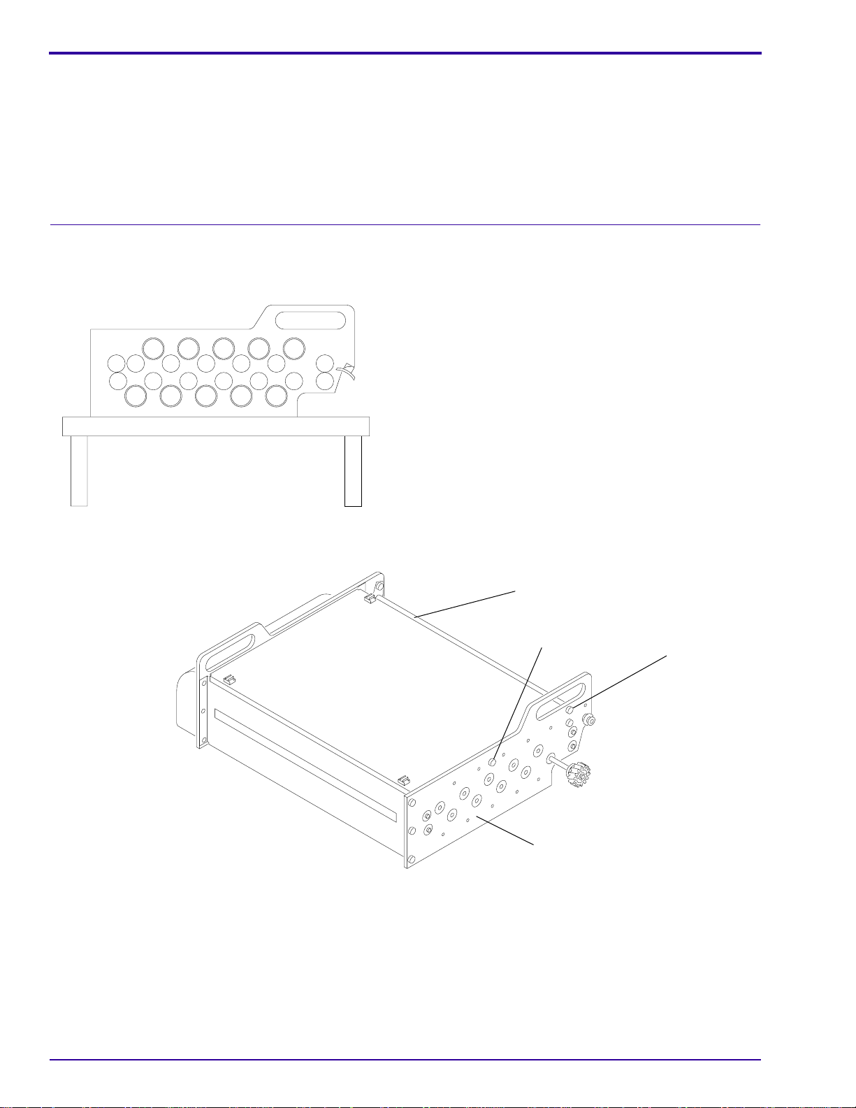
RACK Adjustments
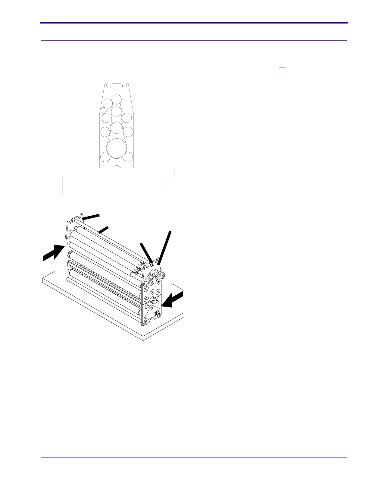
Adjustment for Squareness
Purpose: Use this procedure for the DEVELOPER, FIXER and WASH RACKS.
To adjust the squareness of a DRYER RACK, use the procedure on Page 14.
[1] Remove the RACK from the PROCESSOR.
[2] Place the RACK on a smooth, flat surface.
smooth, flat surface
Adjustments and Replacements
H172_1040ACA
H172_1040AC
SIDE PLATE
TIE ROD
6 SCREWS
H172_1039AA
SIDE PLATE
[3] Loosen the 6 SCREWS on the TIE RODS.
[4] Check that the SIDE PLATES are flat on the flat
surface.
[5] Ifnecessary, apply pressure to the SIDE PLATES.
See the figure.
[6] Tighten the SCREWS.
7C8772 – 12JAN99 9
Page 10
SERVICE MANUAL
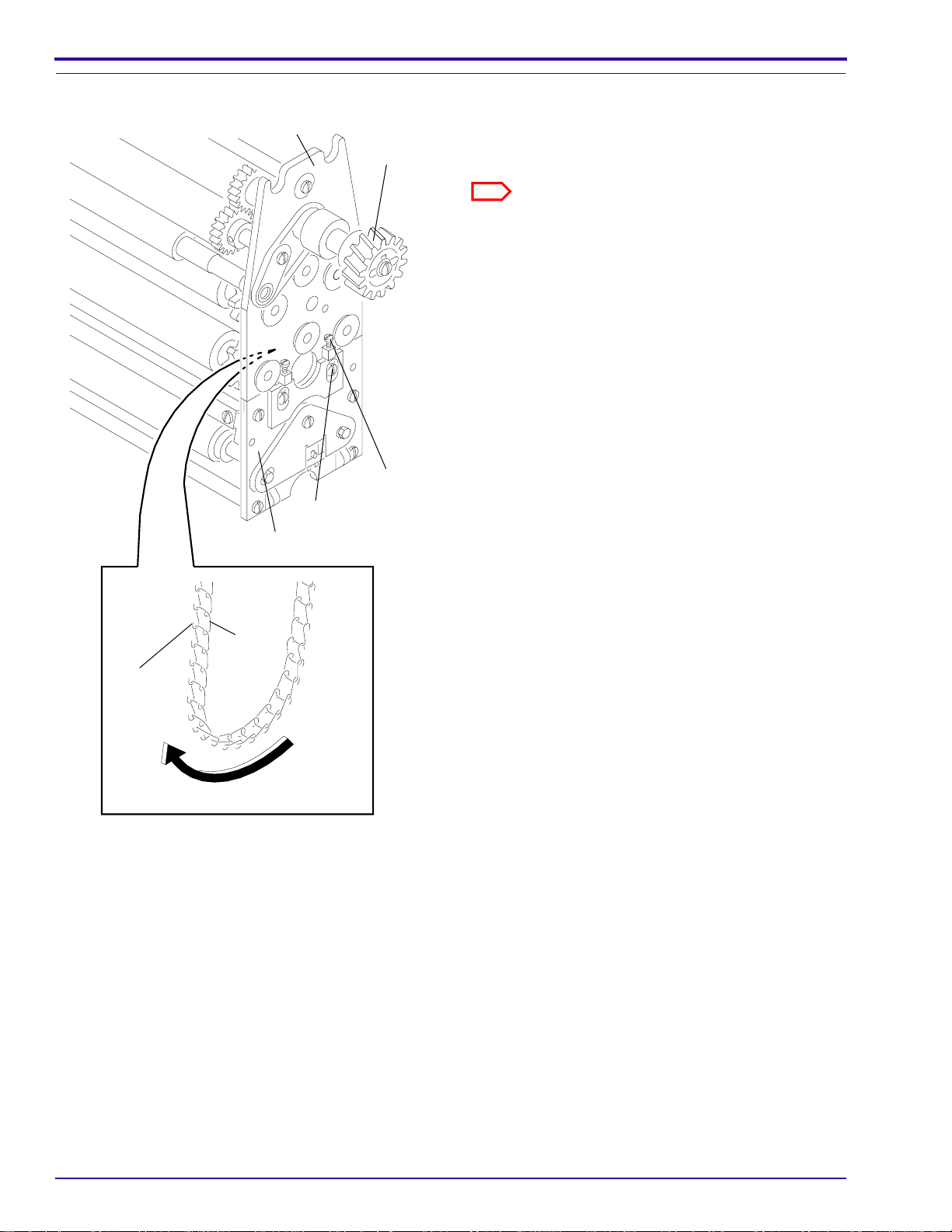
Tension of the DRIVE CHAIN
HOOK
SIDE PLATE
4
TURNAROUND
ASSEMBLY
LINK
ADJUSTING
4
SCREWS
HOLDING
SCREWS
DRIVE
GEAR
[1] Check that the CHAIN is wet with solution.
[2] Check that the RACK is approximately the same
temperature as the solution.
Note
[3] Remove the RACK from the PROCESSOR.
[4] Place the RACK on a smooth, flat surface.
[5] Loosen the 4 HOLDING SCREWS.
[6] On the drive side, loosen the 2 ADJUSTING
SCREWS until the SCREWS do not touch the
SIDE PLATE of the TURNAROUND AY.
[7] Lift the RACK off of the surface and allow the
weight of the TURNAROUND AY to tighten the
CHAIN.
[8] Manually rotate the DRIVE GEAR one full
rotation.
[9] Tighten the 2HOLDING SCREWS onthe DRIVE
side.
[10] Tighten the 2 ADJUSTING SCREWS on the
DRIVE side until the SCREWS touch the SIDE
PLATE of the TURNAROUND AY.
[11] Observe the distance between the RACK SIDE
PLATE and TURNAROUND SIDE PLATE on the
DRIVE side.
[12] Rotate the 2 ADJUSTING SCREWS on the NON-
DRIVE side until the distance between the SIDE
PLATES is the same as the DRIVE side.
[13] Tighten the 2 HOLDING SCREWS on the NON-
DRIVE side.
DRIVE CHAIN
H172_1041CCA
H172_1041CA
10 12JAN99 – 7C8772
Page 11
RACK Replacements
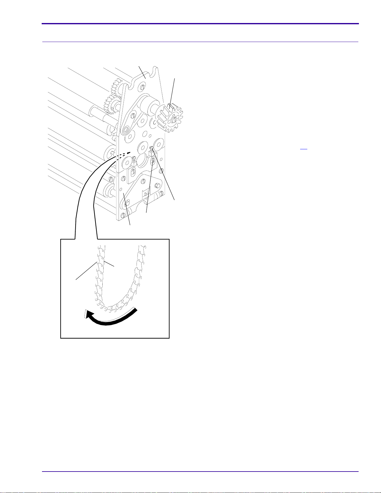
DRIVE CHAIN
Adjustments and Replacements
SIDE PLATE
4
TURNAROUND
ASSEMBLY
ADJUSTING
4
SCREWS
HOLDING
SCREWS
DRIVE
GEAR
[1] Use a SCREWDRIVER to pry open the HOOKS
of a LINK.
[2] Connect the new DRIVE CHAIN totheold DRIVE
CHAIN. Make sure the HOOKSand the openings
of the LINKS are in the correct direction.
[3] Pull the old DRIVE CHAIN through the RACK AY
until the new DRIVE CHAIN is in the correct
position.
[4] Remove the old DRIVE CHAIN.
[5] Connect the ends of the new DRIVE CHAIN.
[6] Use the procedure on Page 10 to adjust the
tension of the DRIVE CHAIN.
HOOK
LINK
DRIVE CHAIN
H172_1041CCA
H172_1041CA
7C8772 – 12JAN99 11
Page 12
SERVICE MANUAL
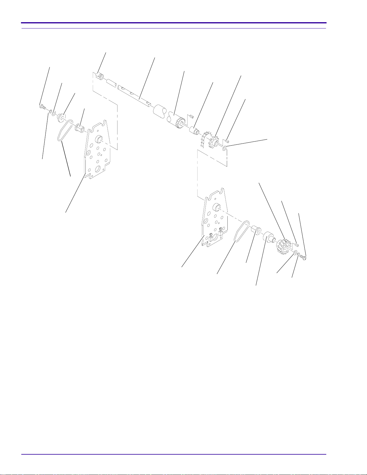
RESILIENT DRIVE ROLLER in the DEVELOPER and FIXER RACKS
SCREW
WASHER
LOCK
WASHER
SPRING
non-drive
SIDE PLATE
SPACER
BEARING
SPACER
SHAFT
RESILIENT
DRIVE
ROLLER
SPROCKET
SPACER
KEY
THRUST
WASHER
DRIVE
GEAR
KEY
SCREW
drive
SIDE PLATE
SPRING
BEARING
SPACER
WASHER
H172_0631DCA
LOCK
WASHER
H172_0631DA
[1] Remove the 2 SPRINGS from the top of the RACK.
[2] Remove from the ends of RESILIENT DRIVE ROLLER outside of the SIDE PLATES:
• SCREWS
• WASHERS
• LOCK WASHERS
• GEAR
• SPACERS
• BEARINGS
[3] Rotate the flat part of the SHAFT to the up position.
[4] Move the DRIVE ROLLER toward the non-drive side and remove the KEY from the DRIVE GEAR.
[5] Move the SHAFT of the DRIVE ROLLER towards the drive side.
[6] Remove:
• THRUST WASHER
• SPROCKET
• SPACER
12 12JAN99 – 7C8772
Page 13
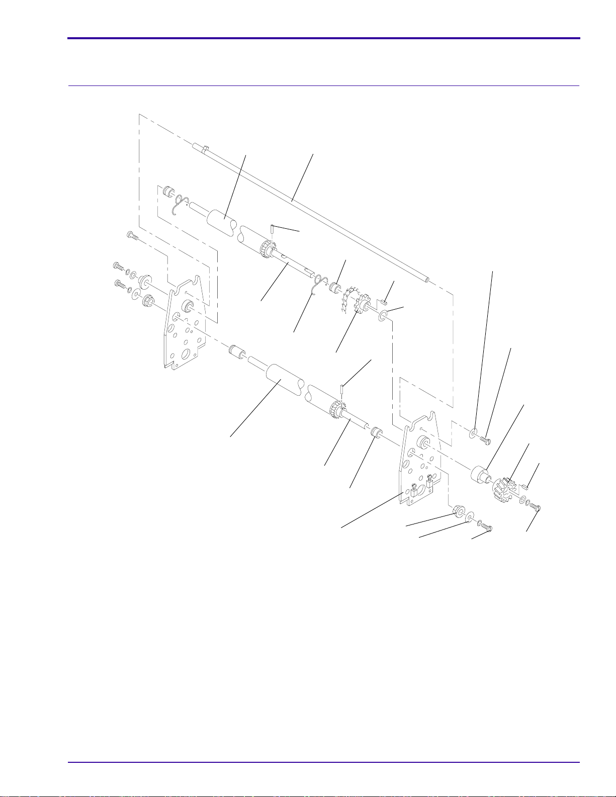
[7] Remove the DRIVE ROLLER.
[8] Reverse the steps to install a new DRIVE ROLLER.
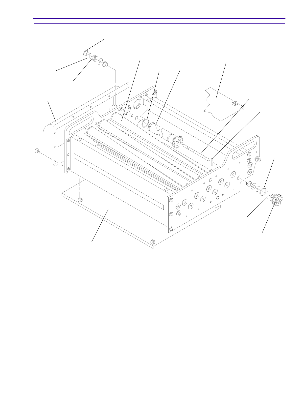
RESILIENT DRIVE ROLLERS in the WASH RACK
RESILIENT
DRIVE
ROLLER
TIE
ROD
PIN
SPACER
Adjustments and Replacements
ID WASHER
KEY
THRUST
WASHER
WASHER
SCREW
2 SCREWS
SPACER
DRIVE
GEAR
KEY
SCREW
H172_0632DCA
H172_0632DA
DRIVEN
ROLLER
SHAFT
2 SPRINGS
SPROCKET
SHAFT
SIDE PLATE
PIN
SPACER
BEARING
[1] Remove from the TIE ROD:
• 2 SCREWS
• ID WASHER
[2] Remove from the ends of DRIVE ROLLER and DRIVEN ROLLER outside of the SIDE PLATES:
• SCREWS
• WASHERS
• DRIVE GEAR
• SPACERS
• BEARINGS
[3] Rotate the flat part of the SHAFT to the up position.
[4] Remove the 2 SPRINGS.
[5] Move the 2 SHAFTS of the DRIVE ROLLER and the DRIVEN ROLLER towards the non-drive SIDE PLATE.
[6] Bend the SIDE PLATE a small distance and remove the ends of the 2 SHAFTS.
7C8772 – 12JAN99 13
Page 14
SERVICE MANUAL
[7] Remove:
• THRUST WASHER
• SPROCKET
• SPACER
[8] Reverse the steps to install a new DRIVE ROLLER and DRIVEN ROLLER.
DRYER RACK
Adjustment for Squareness
[1] Remove the RACK from the PROCESSOR.
[2] Place the CROSSOVER AY on a smooth, flat
surface.
smooth, flat surface
H172_1042AA
TIE ROD
2 TIE ROD
SCREWS
2 NUTS
2 SIDE PLATES
H172_1043BCA
H172_1043BA
[3] Loosen the TIE ROD SCREWS and NUTS.
[4] Press down on the SIDE PLATES so that the SIDE PLATES make uniform contact with the flat surface.
[5] Tighten the TIE ROD SCREWS and NUTS.
14 12JAN99 – 7C8772
Page 15
Installing a new DRIVE ROLLER
O-RING
Adjustments and Replacements
PIN
COLLAR
PLENUM
AIR TUBE
O-RING
DRIVE
ROLLER
COVER
SHAFT
PIN
O-RING
COVER
[1] Remove the DRYER RACK from the PROCESSOR.
[2] Remove:
• top and bottom COVERS
• PLENUM
• first 3 AIR TUBES
• O-RING from the DRIVE GEAR
• PIN
• DRIVE GEAR
[3] From the NON-DRIVE side, remove:
• O-RING from the COLLAR
• PIN
• COLLAR
PIN
DRIVE GEAR
H172_1044DCA
H172_1044DA
7C8772 – 12JAN99 15
Page 16

SERVICE MANUAL
[4] Remove the O-RING from the DRIVE COLLAR on the drive side.
[5] Remove from the DRIVE ROLLER:
• PIN
• SHAFT
[6] Reverse the steps to install a new DRIVE ROLLER.
16 12JAN99 – 7C8772
Page 17
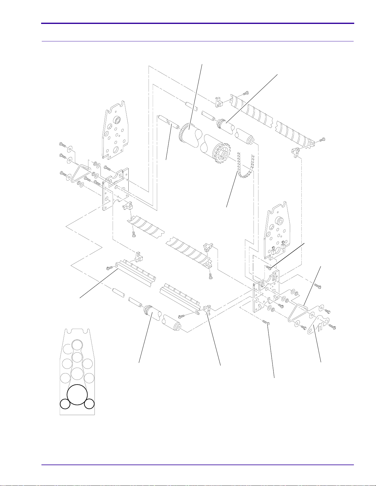
TURNAROUND AY
Disassembling the TURNAROUND AY
SHAFT
Adjustments and Replacements
B ROLLER
A ROLLER
EXIT
GUIDE
SHOE
A ROLLER
CHAIN
2 BRACKETS
4 HOLDING
SCREWS
2 SPRINGS
LOCKING
PLATE
2 SCREWS
H172_0633ECA
H172_0633EA
[1] Remove:
• EXIT GUIDE SHOE and 2 BRACKETS
• ROLLER above the GUIDE SHOE
• 2 SPRINGS and LOCKING PLATE
7C8772 – 12JAN99 17
Page 18

SERVICE MANUAL
• 2 A ROLLERS
[2] Pull the SHAFT from the B ROLLER from the non-drive side.
[3] Remove:
• 4 HOLDING SCREWS
• CHAIN from the B ROLLER
• TURNAROUND AY
Installing a new B ROLLER
See the Figure on Page 17.
[1] Remove:
• TURNOVER AY from the RACK
• 2 SPRINGS
• LOCKING PLATE
• 2 A ROLLERS
• 2 SCREWS
• 2 BRACKETS
• EXIT GUIDE SHOE
• SHAFT, THRUST WASHERS and the BEARING from the B ROLLER
[2] Install:
• new B ROLLER, THRUST WASHERS and the BEARING on the SHAFT
• EXIT GUIDE SHOE
• 2 BRACKETS
• 2 SCREWS
• 2 A ROLLERS
• LOCKING PLATE
• 2 SPRINGS
• TURNOVER AY in the RACK
[3] Use the procedure on Page 10 to adjust the tension on the DRIVE CHAIN, if necessary.
18 12JAN99 – 7C8772
Page 19

Installing new A ROLLERS
Adjustments and Replacements
B ROLLER
A ROLLER
SHAFT
EXIT
GUIDE
SHOE
A ROLLER
CHAIN
2 BRACKETS
4 HOLDING
SCREWS
2 SPRINGS
LOCKING
PLATE
2 SCREWS
H172_0633ECA
H172_0633EA
[1] Remove:
• 2 SPRINGS
• LOCKING PLATE
• SCREW
• A ROLLER from the SHAFT
7C8772 – 12JAN99 19
Page 20

SERVICE MANUAL
[2] Install:
• new A ROLLER on the SHAFT
• A ROLLER in the TURNAROUND AY
• LOCKING PLATE
• SCREW
• 2 SPRINGS
[3] Check that all the GEARS in the TURNAROUND AY engage.
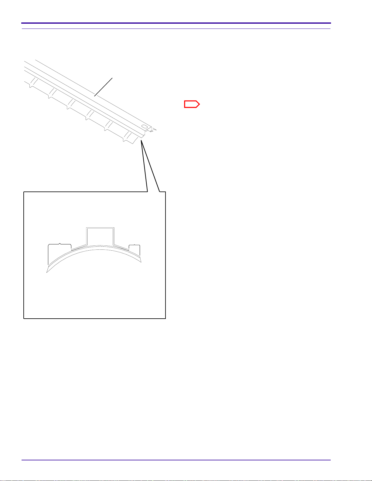
Checking the GUIDE SHOES
[1] Check that the LONG TIPS are in the direction of
GUIDE SHOE
film transport.
LONG
TIP
20 12JAN99 – 7C8772
SHORT
TIP
H172_1045CCA
H172_1045CA
Page 21

MAIN DRIVE
Adjusting the MAIN DRIVE CHAIN
Adjustments and Replacements
4 MOUNTING
SCREWS
DRIVE
CHAIN
CHAIN
GUARD
2 GUARD
SCREWS
Warning
• Dangerous Voltage
• Moving Parts
[1] Disconnect the PROCESSOR from the main power.
[2] Remove:
• DRIVE SIDE PANEL
• 2 GUARD SCREWS
• CHAIN GUARD
• 2 SCREWS
• MOTOR CAGE
[3] Loosen the 4 MOUNTING SCREWS.
MOTOR
MOTOR
CAGE
2 SCREWS
H172_1046BCA
H172_1046BA
Caution
Do not tighten the DRIVE CHAIN excessively.
[4] Move the DRIVE MOTOR to tighten the DRIVE CHAIN.
[5] Tighten the 4 MOUNTING SCREWS.
[6] Install:
• MOTOR CAGE
• 2 SCREWS
• CHAIN GUARD
• 2 GUARD SCREWS
• DRIVE SIDE PANEL
7C8772 – 12JAN99 21
Page 22

SERVICE MANUAL
Aligning the MAIN DRIVE MOTOR
3 SETSCREWS
2 SPROCKETS
DRIVE
SHAFT
Warning
• Dangerous Voltage
• Moving Parts
[1] Disconnect the PROCESSOR from the main
power.
[2] Remove:
• DRIVE SIDE PANEL
• 2 GUARD SCREWS
• CHAIN GUARD
[3] Loosen the 3 SETSCREWS.
[4] Align the SPROCKETS with eachother.
[5] Tighten the 3 SETSCREWS.
[6] Check:
• DRIVE CHAIN does not touch the
MOUNTING PLATE
• SPROCKET on the DRIVE SHAFT does not
touch the DRYER RACK
[7] Install:
• DRIVE SIDE PANEL
• 2 GUARD SCREWS
• CHAIN GUARD
MOTOR
SHAFT
DRIVE
CHAIN
MOUNTING
PLATE
H172_1047CCA
H172_1047CC
22 12JAN99 – 7C8772
Page 23

Adjustments and Replacements
Installing a new MAIN DRIVE SHAFT, WORM GEARS or BEARING BLOCKS
WORM
GEAR
DRIVE
SHAFT
SPACER
4 SCREWS
2 BEARING
BLOCKS
2 SHIMS
SETSCREW
DRIVE
CHAIN
CHAIN
GUARD
PIN
4 MOUNTING
SCREWS
H172_0634DCA
H172_0634DA
[1] Remove the CHAIN GUARD.
[2] Loosen the 4 MOUNTING SCREWS.
[3] Remove:
• DRIVE CHAIN
• 4 SCREWS from the 2 BEARING BLOCKS
• SHIMS
• DRIVE SHAFT
[4] Install the new WORM GEAR or BEARING BLOCKS.
[5] Place the SHIMS under the BEARING BLOCKS.
[6] Install, but do not tighten, the 4 SCREWS in the BEARING BLOCKS.
[7] Adjust the position of the BEARING BLOCKS until the DRIVE SHAFT moves freely.
7C8772 – 12JAN99 23
Page 24

SERVICE MANUAL
Caution
Do not tighten the SCREWS excessively.
[8] Tighten the 4 SCREWS.
[9] Use the procedure on Page 21 to adjust the tension of the MAIN DRIVE CHAIN.
[10] Tighten the 4 MOUNTING SCREWS.
[11] Install the CHAIN GUARD.
DRYER HEATER
Adjusting the Temperature
DRYER
TEMPERATURE
CONTROL
KNOB
Factors which determine the correct temperature are:
Use the lowest temperature necessary to dry the film.
Important
• condition of the air
• amount and type of the film
[1] Rotate the DRYER TEMPERATURE CONTROL
KNOB to adjust the temperature:
• clockwise to increase the temperature
• counterclockwise to decrease the
temperature
H172_1065ACA
H172_1065AC
24 12JAN99 – 7C8772
Page 25

Installing a new BLOWER AY
Warning
Dangerous Voltage
[1] Disconnect the main power.
4 MOUNTING
SCREWS
ELECTRICAL
BOX
Adjustments and Replacements
RECEIVING
END
COVER
BLOWER
MOTOR
800
CIRCUIT
BOARD
DRYER
HEATER
H172_1048DCA
H172_1048DA
[2] Remove:
• TOP COVER
• DRYER RACK
• RECEIVING END COVER
• SIDE PANELS
ESD
Possible damage from electrostatic discharge.
7C8772 – 12JAN99 25
Page 26

SERVICE MANUAL
[3] Disconnect from the 800 CIRCUIT BOARD:
(Not visible in the graphic)
• CONNECTOR 801
• CONNECTOR 802
[4] Disconnect the CABLE ASSEMBLY from the ELECTRICAL BOX.
[5] Remove:
• MOUNTING SCREWS
• BLOWER MOTOR
[6] Reverse the steps to install the new BLOWER MOTOR.
Installing a new DRYER HEATER or HEATER CORE
Warning
Dangerous Voltage
[1] Disconnect the main power.
4 MOUNTING
SCREWS
ELECTRICAL
BOX
RECEIVING
END
COVER
800
CIRCUIT
BOARD
HEATER
TOP COVER
2 SCREWS
HEATER
CORE
2 SCREWS
EXHAUST
HOSE
H172_1048DCB
H172_1048DA
26 12JAN99 – 7C8772
Page 27

[2] Remove:
• TOP COVER
• DRYER RACK
• RECEIVING END COVER
• SIDE PANELS
ESD
Possible damage from electrostatic discharge.
[3] Disconnect from the 800 CIRCUIT BOARD:
(Not visible in the graphic)
• CONNECTOR 801
• CONNECTOR 802
[4] Disconnect from the ELECTRICAL BOX:
• TB2-1
• TB2-3
• TB2-5
• GROUND WIRE
[5] Remove:
• EXHAUST HOSE
• 6 MOUNTING SCREWS
• 4 SCREWS
• DRYER HEATER
[6] To install a new DRYER HEATER, reverse the steps above.
To install a new HEATER CORE, continue with Step 7.
[7] Loosen the 2 SCREWS.
[8] Remove the HEATER TOP COVER.
[9] Remove from inside the DRYER HEATER:
(Not visible in the graphic)
• 4 HEX NUTS
• 4 MOUNTING SCREWS
• HEATER CORE
[10] Reverse the steps to install the new HEATER CORE.
Adjustments and Replacements
PLUMBING System Adjustments
Adjusting the Developer Temperature
[1] Remove the TOP COVER.
7C8772 – 12JAN99 27
Page 28

SERVICE MANUAL
Insert THERMOMETER
here
H172_1006BCB
H172_1006BC
[2] Wait until the TEMPERATURE READY LIGHT blinks slowly or does not illuminate.
[3] Insert a THERMOMETER intotheDEVELOPERTANK on thenon-drivesideofthePROCESSORbetweenthe
SIDE PLATE of the DEVELOPER RACK and the RACK SUPPORT.
[4] Check that the temperature of the developer is correct for the operating cycle of the PROCESSOR.
Cycle Temperature
Standard 33.3 0.3°C (92.0 0.5°F)
Rapid 34.4 0.3°C (94.0 0.5°F)
100 CIRCUIT BOARD
R2
[5] If the developer temperature is correct, advance to Step 9.
ELECTRICAL
BOX
H172_1031BCB
H172_1031BC
Warning
• Dangerous Voltage
• Possible damage from electrostatic discharge
[6] If the developer temperature is not correct:
(a) Remove the DRIVE SIDE PANEL.
(b) Open the DOOR on the ELECTRICAL BOX.
28 12JAN99 – 7C8772
Page 29

Adjustments and Replacements
(c) Use the POTENTIOMETER ADJUSTING TOOL TL-1481 to adjust R2 on the 100 CIRCUIT BOARD:
• Rotate R2 clockwise to increase the temperature
• Rotate R2 counterclockwise to decrease the temperature
[7] Allow the developer solution to reach a stable temperature.
[8] Do Step 4.
[9] Close the DOOR on the ELECTRICAL BOX.
[10] Install the DRIVE SIDE PANEL and TOP COVER.
Checking the Replenishment Rates
UPPER ROLLER
DETECTOR CROSSOVER
ASSEMBLY
2 DETECTOR
SWITCHES
H172_1006BCA
H172_1006BC
DEVELOPER TUBING
METAL LATCH
QUICK
DISCONNECT
GRADUATED
CYLINDER
FIXER TUBING
Warning
Wear protective eyewear. The replenishment solutions
are pumped quickly and might splash.
[1] Remove the TOP COVER.
[2] Lift the UPPER ROLLER of the DETECTOR
CROSSOVER AY.
[3] Checkthatthereplenishmentsolutionsflowfreely
through the TUBING located along the DRIVE
SIDE RACKS.
[4] Disconnect the DEVELOPER TUBING by
pressing the METAL LATCH.
Note
H172_1005ACA
H172_1005AC
[5] Pull the DEVELOPER TUBING slightly and rotate it over the edge of the FRAME and into a GRADUATED
CYLINDER.
[6] Lift the UPPER ROLLER of the DETECTOR CROSSOVER AY for the correct time:
Cycle Time
Standard 34 seconds
Rapid 25 seconds
The DEVELOPER TUBING might be identified with a
red WIRE TIE.
[7] When the REPLENISHMENTPUMP stops, check thatthe amount of solution in the GRADUATED CYLINDER
is correct for the film size and use condition. See the table on Page 30.
7C8772 – 12JAN99 29
Page 30

SERVICE MANUAL
[8] If the replenishment rate is notcorrect,dothe procedure “Adjusting the REPLENISHMENT PUMP”onPage30.
[9] ConnecttheDEVELOPERTUBINGby pushing it into theMETAL LATCH until the DEVELOPERTUBINGsnaps
in place.
[10] Check the replenishment flow rate of the fixer solution by doing Steps 4 - 9 with the FIXER TUBING.
[11] Install the TOP COVER.
Replenishment Flow Rate,
mL per 35 x 43 cm
34 seconds for Standard Cycle
25 seconds for Rapid Cycle
Developer Fixer
Film Size Processed Use Condition
Average Amount of Film
per 8 Hours of
PROCESSOR Operation
Only roll films 35 cm wide High 105 Linear feet or more 50 70
Medium 35 - 105 linear feet 65 85
Low 35 linear feet or less* 80 100
Only 35 x 35 cm film High 90 sheets or more 50 70
Medium 30 - 90 sheets 65 85
Low 30 sheets or less* 80 100
Average size intermix film High 115 sheets or more 50 70
Medium 40 - 115 sheets 65 85
Low 40 sheets or less* 80 100
Only 35 x 43 cm film High 75 sheets or more 60 85
Medium 25 - 75 sheets 80 100
Low 25 sheets or less* 100 120
* If sensitometry does not stay within control limits, flooded replenishment may be needed. Order and install
FLOODED REPLENISHMENT KIT 419779.
Note
For more information and for new recommended processing instructions, see SERVICE BULLETIN 30, Pub. No.
632661.
Adjusting the REPLENISHMENT PUMP
BRACKET
TOP COVER
[1] Remove:
• TOP COVER
• RECEIVING BIN
• 2 SCREWS
• PUMP COVER
PUMP COVER
2 SCREWS
30 12JAN99 – 7C8772
H172_1028ACA
H172_1028AC
Page 31

SETSCREW
Adjustments and Replacements
REPLENISHMENT PUMP
ADJUSTMENT
SCREW
Do not
adjust!
LOCKNUT
H172_1029BCA
H172_1029BC
BRACKET
HOLE
ADJUSTMENT SCREW
DECREASE
INCREASE
OUTPUT
[2] Check to see if the ADJUSTMENT SCREW is visible through the BRACKET HOLE.
[3] If the ADJUSTMENT SCREW is visible, advance to Step 5.
UPPER ROLLER
DETECTOR CROSSOVER
ASSEMBLY
2 DETECTOR
SWITCHES
H172_1006BCA
H172_1006BC
[4] If the ADJUSTMENT SCREW is not visible, operate the REPLENISHMENT PUMP until the ADJUSTMENT
SCREW is visible by lifting the UPPER ROLLER of the DETECTOR CROSSOVER AY.
Caution
Do not adjust the LOCKNUT.
[5] Loosen the SETSCREW.
[6] Rotate the ADJUSTMENT SCREW to change the flow rate:
• clockwise to increase the flow rate.
• counterclockwise to decrease the flow rate.
[7] Tighten the SETSCREW.
[8] Check the Replenishment Rates. See Page 29
[9] If the flow rate is not correct, do Steps 3 - 8 again
[10] Install:
• PUMP COVER
• 2 SCREWS
• TOP COVER
• RECEIVING BIN
7C8772 – 12JAN99 31
Page 32

SERVICE MANUAL
PLUMBING System Replacements
DEVELOPER HEATER
Warning
Dangerous Voltage
[1] Disconnect the main power.
DEVELOPER
TANK
DEVELOPER
HEATER
TUBE
2 SCREWS
TUBE
H172_1049BCA
H172_1049BC
[2] Drain the DEVELOPER TANK or apply CLAMPS to the 2 TUBES on the THERMOWELL.
ESD
Possible damage from electrostatic discharge.
[3] Open the ELECTRICAL BOX.
[4] Disconnect the wires of the DEVELOPER HEATER at TB2-9 and TB2-10.
Warning
When you remove the DEVELOPERHEATERfromthe THERMOWELL, there might be aleakageof solution. Clean
all spills.
[5] Remove:
• 2 SCREWS
• THERMOWELL
• DEVELOPER HEATER from the THERMOWELL
[6] Apply SEALANT TL-3230 to the THREADS on the new DEVELOPER HEATER.
[7] Insert the new DEVELOPER HEATER into the THERMOWELL.
32 12JAN99 – 7C8772
Page 33

Adjustments and Replacements
5 mm
(13/64 in.)
13.9 cm
(5.500 .060 in.)
THERMOWELL
HEATER LOCATOR
DEVELOPER
HEATER
60
HEATER
LOCATOR
H172_1050BCA
H172_1050BA
[8] Use the HEATER LOCATORontheTHERMOWELLtocheck the correct location of the DEVELOPER HEATER.
Caution
Do not tighten the DEVELOPER HEATER excessively or you will cause damage to the THERMOWELL.
[9] Use your hand to tighten the DEVELOPER HEATER, then tighten the DEVELOPER HEATER an additional 1/
2 rotation.
[10] Install the THERMOWELL using 2 SCREWS.
[11] Connect the wires of the DEVELOPER HEATER at TB2-9 and TB2-10.
[12] Close the ELECTRICAL BOX.
[13] Fill the DEVELOPER TANK or remove the CLAMPS from the TUBES on the THERMOWELL.
DEVELOPER THERMISTOR
Warning
Dangerous Voltage
[1] Disconnect the main power.
[2] Drain the DEVELOPER TANK or apply CLAMPS to the 2 TUBES on the THERMOWELL. See the Figure on
Page 32.
ESD
Possible damage from electrostatic discharge.
[3] Open the ELECTRICAL BOX.
[4] Disconnect the wires of the DEVELOPER THERMISTOR at TB4-13 and TB4-14.
Warning
When you removethe DEVELOPER THERMISTOR fromthe THERMOWELL, there might be a leakageof solution.
Clean all spills.
[5] Remove the DEVELOPER THERMISTOR from the THERMOWELL.
[6] Apply SEALANT TL-3230 to the THREADS on the new DEVELOPER THERMISTOR.
7C8772 – 12JAN99 33
Page 34

SERVICE MANUAL
DEVELOPER
THERMISTOR
4 mm
(5/32 in.)
THERMOWELL
Caution
You must install the DEVELOPER THERMISTOR at the correct distance from the THERMOWELL.
[7] Install the new DEVELOPER THERMISTOR 4 mm (5/32 in.) from the THERMOWELL.
[8] Connect the wires of the new DEVELOPER THERMISTOR at TB4-13 and TB4-14.
[9] Close the ELECTRICAL BOX.
[10] Fill the DEVELOPER TANK or remove the CLAMPS from the TUBES on the THERMOWELL.
H172_1051BCA
H172_1051BA
DEVELOPER OVER-TEMPERATURE THERMOSTAT
Warning
Dangerous Voltage
[1] Disconnect the main power.
[2] Drain the DEVELOPER TANK or apply CLAMPS to the 2 TUBES on the THERMOWELL. See the Figure on
Page 32.
ESD
Possible damage from electrostatic discharge.
[3] Open the ELECTRICAL BOX.
[4] Disconnect the wires of the DEVELOPER OVER-TEMPERATURE THERMOSTAT at:
• TB4-8
• TB4-9
• TB4-15
• TB4-16
Warning
When you remove the DEVELOPER OVER-TEMPERATURE THERMOSTATfromtheTHERMOWELL,there might
be a leakage of solution. Clean all spills.
[5] Remove the DEVELOPER OVER-TEMPERATURE THERMOSTAT from the THERMOWELL.
[6] Apply SEALANT TL-3230 to the THREADS on the new DEVELOPER OVER-TEMPERATURE THERMOSTAT.
34 12JAN99 – 7C8772
Page 35

Adjustments and Replacements
DEVELOPER
THERMISTOR
5 mm
(13/64 in.)
13.9 cm
(5.500 + .060 in.)
−
THERMOWELL
DEVELOPER
OVER-TEMPERATURE
THERMOSTAT
H172_1052BCA
H172_1052BA
Caution
You must install the DEVELOPER OVER-TEMPERATURE THERMOSTAT at the correct distance from the
THERMOWELL.
[7] Install the new DEVELOPER OVER-TEMPERATURE THERMOSTAT 5 mm (13/64 in.) from the
THERMOWELL.
[8] Connect the wires of the new DEVELOPER OVER-TEMPERATURE THERMOSTAT to:
• TB4-8
• TB4-9
• TB4-15
• TB4-16
[9] Close the ELECTRICAL BOX.
[10] Fill the DEVELOPER TANK or remove the CLAMPS from the TUBES on the THERMOWELL.
7C8772 – 12JAN99 35
Page 36

SERVICE MANUAL
HEAT EXCHANGER
Purpose: Use this procedure for the replacement of the HEAT EXCHANGER for the FIXER TANK or the
WASH TANK.
Warning
RACK
SUPPORT
2 SCREWS
2 TANK
CLIPS
Dangerous Voltage
[1] Disconnect the main power.
[2] Disconnect the watersupplytothePROCESSOR.
[3] Remove:
• TOP COVER
• 2 SIDE PANELS
[4] Drain the 3 TANKS.
[5] Remove:
• 2 SCREWS
• RACK SUPPORT
• TANK SEALS
• TANK CLIP
[6] Disconnect all TUBING from the TANK.
2 TANK
SEALS
H172_1053CCA
H173_1053CA
36 12JAN99 – 7C8772
Page 37

Adjustments and Replacements
2 GASKETS
2 FITTINGS
WATER INLET
TUBE
TANK
HEATER
EXCHANGER
2 O-RINGS
2 WASHERS
2 GLAND NUTS
[7] Remove if necessary:
• 2 FITTINGS
• WATER INLET TUBE
[8] To remove the TANK, lift the non-drive side of the
TANK first.
[9] Remove from the TANK:
• 2 GLAND NUTS
• 2 O-RINGS
• 2 WASHERS
• HEAT EXCHANGER
Important
Use new GASKETS if you are installing a FIXER TANK.
[10] Install:
• new HEAT EXCHANGER
• 2 O-RINGS
• 2 WASHERS
• 2 GLAND NUTS
• TANK
• 2 FITTINGS
• 2 GASKETS
• WATER INLET TUBE
• TANK SEALS
• TANK CLIP
• TUBING
• RACK SUPPORT
H172_1054CCA
H172_1054CA
[11] Move the RACK SUPPORT toward the non-drive side of the PROCESSOR.
[12] Install the 2 SCREWS.
[13] Fill the TANKS with water.
[14] Check for leakage.
[15] Drain the water from the DEVELOPER TANK and the FIXER TANK.
[16] Fill the DEVELOPER TANK and the FIXER TANK with the correct solution.
[17] Connect the water supply.
Warning
Dangerous Voltage
[18] Connect the main power.
7C8772 – 12JAN99 37
Page 38

SERVICE MANUAL
RECIRCULATION PUMP
Warning
Dangerous Voltage
[1] Disconnect the main power.
[2] Disconnect the water supply to the PROCESSOR.
[3] Remove:
• TOP COVER
• 2 SIDE PANELS
[4] Drain the 3 TANKS.
[5] Install PINCH CLAMPS on the TUBING to the RECIRCULATION PUMP to prevent leakage of solution.
[6] Disconnect the TUBING to the RECIRCULATION PUMP.
[7] Remove:
• MOUNTING SCREWS
• RECIRCULATION PUMP
• MOTOR LEADS (not visible in figure)
[8] Install:
• new RECIRCULATION PUMP
• MOTOR LEADS (not visible in figure)
• MOUNTING SCREWS
[9] Connect the TUBING to the RECIRCULATION PUMP.
[10] Connect the water supply.
[11] Remove the PINCH CLAMPS from the TUBING.
[12] Fill the 3 TANKS with water.
Warning
Dangerous Voltage
[13] Connect the main power.
MOUNTING
SCREW
RECIRCULATION PUMP
H172_1055BCA
H172_1055BA
38 12JAN99 – 7C8772
Page 39

Adjustments and Replacements
Caution
Do not operate the RECIRCULATION PUMP if the TANKS are empty.
[14] Actuate the RECIRCULATION PUMP.
[15] Check for:
• agitation of the water in the TANK
• leakage
[16] Drain the water from the DEVELOPER TANK and the FIXER TANK.
[17] Fill the DEVELOPER TANK and the FIXER TANK with the correct solution.
O-RING in the RECIRCULATION PUMP
Warning
Dangerous Voltage
[1] Disconnect the main power.
[2] Disconnect the water supply to the PROCESSOR.
[3] Remove:
• TOP COVER
• 2 SIDE PANELS
[4] Install PINCH CLAMPS on the TUBING to the RECIRCULATION PUMP to prevent leakage of solution.
7C8772 – 12JAN99 39
Page 40

SERVICE MANUAL
O-RING
4 WING
NUTS
OUTER
PUMP
HOUSING
SCREW
[5] Remove:
• 4 WING NUTS
• OUTER PUMP HOUSING
• O-RING
Important
The new O-RING must seat correctly.
[6] Install:
• O-RING
• OUTER PUMP HOUSING
• 4 WING NUTS
[7] Remove the PINCH CLAMPS from the TUBING.
WASHER
IMPELLER
SHAFT
H172_1056DCA
H172_1056DA
40 12JAN99 – 7C8772
Page 41

Warning
Dangerous Voltage
[8] Connect the main power.
Caution
Do not operate the RECIRCULATION PUMP if the TANKS are empty.
[9] Actuate the RECIRCULATION PUMP.
[10] Check for:
• agitation of the solution in the TANK
• leakage
REPLENISHMENT PUMP
Adjustments and Replacements
EXIT
PANEL
PUMP
COVER
DRYER TEMPERATURE CONTROL
KNOB
2 REPLENISHMENT PUMPS
2 WASHERS
TOP COVER
2 SIDE PANELS
H172_1028ACB
H172_1028AC
Warning
Dangerous Voltage
[1] Disconnect the main power.
[2] Disconnect the watersupplytothePROCESSOR.
[3] Remove:
• TOP COVER
• 2 SIDE PANELS
• RECEIVING BIN
• DRYER TEMPERATURE CONTROL KNOB
• PUMP COVER
• EXIT PANEL
REPLENISHER TUBE LINES
2 LOCK WASHERS
2 SCREWS
H172_1057BCA
H172_1057BC
[4] Disconnect:
• MOTOR LEAD TB3-6
• MOTOR LEAD TB3-2
• GROUND WIRE
[5] Install PINCH CLAMPS on the TUBING to the REPLENISHMENT PUMP.
7C8772 – 12JAN99 41
Page 42

SERVICE MANUAL
[6] Disconnect the REPLENISHER TUBE LINES.
[7] Remove:
• 2 SCREWS
• 2 LOCK WASHERS
• 2 WASHERS
• REPLENISHMENT PUMP
[8] Reverse the steps to install a new REPLENISHMENT PUMP.
42 12JAN99 – 7C8772
Page 43

Periodic Maintenance
Section 3: Periodic Maintenance
Procedure and Schedule
Important
The Periodic Maintenance procedures include additional procedures which are not in the OPERATOR MANUAL,
Publication No. 7C8770. For optimum operation of the PROCESSOR, it is important to do these procedures.
[1] Process 5 sheets of unprocessed film.
[2] Check the film for artifacts.
[3] Do all of the Monthly Maintenance Procedures first.
[4] Do the procedure for lubrication on Page 51.
[5] Check the specifications of the site.
[6] Process 5 sheets of film.
[7] Check the film for artifacts.
Monthly Maintenance Procedures
DETECTOR SWITCHES
[1] Check that the DETECTOR SWITCHES operate the REPLENISHMENT PUMP.
[2] Adjust the DETECTOR SWITCHES if necessary. Use the procedure on Page 5.
DETECTOR CROSSOVER AY
[1] Use a damp, lint-free CLOTH or a SPONGE to clean the DETECTOR ROLLERS.
[2] Check:
• ROCKER ARM moves freely
• ROCKER ARM does not have corrosion
• DETECTOR CROSSOVER AY for squareness
[3] Clean the ROCKER ARM if it does not move freely.
[4] Install a new ROCKER ARM if it has corrosion.
[5] Check the DETECTOR CROSSOVER AY for squareness. Use the procedure on Page 7.
[6] Check that the DETECTOR CROSSOVER AY is correctly seated.
CROSSOVER AYs
[1] Remove the CROSSOVER AYs from the PROCESSOR.
[2] Rinse the CROSSOVER AYs with water.
[3] Use warm water and a soft BRUSH to clean the CROSSOVER AYs, or use:
Cleaning Solution Type of CROSSOVER
DEVELOPER SYSTEM CLEANER and
NEUTRALIZER, Catalog No. 843 4615
FIXER/WASH SYSTEM CLEANER,
Catalog No. 139 5110
7C8772 – 12JAN99 43
DEVELOPER/FIXER CROSSOVER
FIXER/WASH CROSSOVER
Page 44

SERVICE MANUAL
BRACKET
ROLLER
ROLLER
GEAR
NUT
SPRING
DRIVE
GEAR
GUIDE
SHOE
BEARING
[4] Check that the surface of the RESILIENT ROLLER is smooth. Install a replacement if necessary.
[5] Check components for wear or broken parts. Install replacements if necessary:
• SPRINGS
• ROLLER GEARS
• BEARING
• BRACKET
• NUTS
• DRIVE GEAR
[6] Check the CROSSOVER AYs for squareness. Use the procedure on Page 7.
RACK AYs
[1] Remove the RACKS from the PROCESSOR.
[2] Rinse the RACKS with warm water.
[3] Use warm water and a soft BRUSH to clean the RACKS, or use:
Cleaning Solution RACK
DEVELOPER SYSTEM CLEANER and
NEUTRALIZER, Catalog No. 843 4615
FIXER/WASH SYSTEM CLEANER,
Catalog No. 139 5110
DEVELOPER
FIXER
WASH
H172_1058BCA
H172_1058BA
Note
The ROLLERS might change color with time. This change is normal.
44 12JAN99 – 7C8772
Page 45

BEARING
Periodic Maintenance
bottom view
ROLLER
top view
LOCKING
PLATE
[4] Check:
• SPRINGS for correct tension and for wear
• ROLLERS and BEARINGS rotate freely
• ROLLERS move freely in the LOCKING PLATES
• surfaces of the ROLLERS are smooth
[5] Install replacement SPRINGS and ROLLERS if necessary.
SHAFT
SPRING
BEARING
H172_1060DCA
H172_1060DA
7C8772 – 12JAN99 45
Page 46

SERVICE MANUAL
DRIVE CHAIN
SPROCKET
GEAR
TURNAROUND
ASSEMBLY
SHAFT
DRIVE
GEAR
SPRING
LOCKING
PLATE
[1] Manually rotate the DRIVE GEAR to check the
LINKS of the DRIVE CHAIN.
Important
The tension of the DRIVE CHAIN must be correct.
• If the DRIVE CHAIN is too tight, the ROLLERS will
bind and cause wear of the BEARING.
• IftheDRIVECHAINistooloose,theROLLERSwill
not move smoothly.
[2] Check the tension of the DRIVE CHAIN.
[3] If necessary, adjust the tension of the DRIVE
CHAIN using the procedure on Page 10.
LINK
DRIVE CHAIN
H172_1041CCB
H172_1041CA
46 12JAN99 – 7C8772
Page 47

DRYER
Periodic Maintenance
SPRING
AIR TUBE
GEAR
ROLLER
H172_1059BCA
H172_1059BA
[1] Remove the DRYER RACK from the PROCESSOR.
[2] Check for broken GEARS and install new ROLLERS if necessary.
[3] Check the SPRINGS, not visible in the graphic, for correct tension and for wear. Install new SPRINGS if
necessary.
[4] Check and adjust the temperature of the DRYER. Use the procedure on Page 24.
MAIN DRIVE
WORM
GEAR
DRIVE
CHAIN
SPROCKET
[1] Check the DRIVE CHAIN for wear and install a new DRIVE CHAIN if necessary.
[2] Check and adjust the tension of the DRIVE CHAIN. Use the procedure on Page 21.
[3] Lubricate the DRIVE CHAIN if necessary. Use the procedure on Page 51.
[4] Check for wear and install replacements if necessary:
• BEARINGS
• SPROCKETS
• WORM GEARS
[5] Check the TEETH of the SPROCKETS. If the TEETH are sharp, install new SPROCKETS.
[6] Check the WORM GEARS for burrs. Install new WORM GEARS if necessary.
[7] Rinse the WORM GEARS with warm water.
BEARING
H172_1061BCA
H172_1061BA
7C8772 – 12JAN99 47
Page 48

SERVICE MANUAL
PLUMBING
[1] Check components and connections for leakage:
• RECIRCULATION PUMPS
• VALVES
• TUBING
• TANKS
[2] Check that the temperature of the water supply is 4-30°C (40-85°F).
WATER
INLET
TUBE
[3] Check the flow rate of the water supply:
(a) Drain the TANKS.
(b) Remove:
• FIXER/WASH CROSSOVER
• DRYER RACK
• WASH RACK
(c) Start the water supply.
(d) Measure the flow rateat the WATER INLETTUBE. The rate shouldbe 946 mL/min. (1/4gal/min.), +10%,
-0%.
RECIRCULATION PUMPS
Caution
Do not operate the RECIRCULATION PUMP if the TANKS are empty.
[1] Actuate the RECIRCULATION PUMPS.
[2] Check for:
• leakage
• agitation of the solution in the TANKS
• excessive noise from the RECIRCULATION PUMPS
H172_1062BCA
H172_1062BC
48 12JAN99 – 7C8772
Page 49

Periodic Maintenance
DEVELOPER FILTER
Important
Install a new DEVELOPER FILTER monthly or after approximately 1000 sheets of film have been processed.
[1] Soak the new DEVELOPER FILTER in warm
water for 30 seconds.
[2] Remove the FILTER AY.
[3] Lift the FILTER AYabove the levelof the solutions.
Note
Keep the FILTER AY above the level of the solutions
during the procedure to prevent draining the solutions
from the TANKS.
[4] Disassemble:
• FILTER HOUSING
• DEVELOPER FILTER
• O-RING
• CAP
CAP
O-RING
DEVELOPER
FILTER
FILTER
HOUSING
H172_1026CCA
H172_1026CC
Temperature of the Developer Solution
Important
The O-RING must be seated correctly.
[5] Assemble:
• FILTER HOUSING
• new DEVELOPER FILTER
• O-RING
• CAP
[6] Install the FILTER HOUSING in the
PROCESSOR.
[7] Check that the TUBINGconnected to the FILTER
HOUSING is not bent.
[1] Do the procedure on Page 27.
7C8772 – 12JAN99 49
Page 50

SERVICE MANUAL
Chemical Replenishment
[1] Check the replenishment rates. Use the procedure on Page 29.
[2] Check the STRAINERS for debris:
(a) Place CLAMPS on the TUBING to stop the flow of replenishment solution.
(b) Disassemble the STRAINER AYs.
(c) Use a BRUSH and warm water to clean the STRAINER AYs and the SCREENS.
STRAINER ASSEMBLY
SCREEN
H172_1063BCA
H172_1063BA
INTERLOCK SWITCH
MAGNET
TOP COVER
MAGNET
INTERLOCK
SWITCH
H172_1064BCA
H172_1064BC
[1] Press the RUN/STANDBY SWITCH.
Warning
Moving Parts
[2] Remove the TOP COVER.
[3] Check that the components stop operating:
• MAIN DRIVE MOTOR
• BLOWER MOTOR
• DRYER HEATER
[4] If the components do not stop when the TOP COVER is removed, install a new INTERLOCK SWITCH.
50 12JAN99 – 7C8772
Page 51

Periodic Maintenance
Lubrication Procedure and Schedule
Warning
Dangerous Voltage
[1] Disconnect the main power before applying lubrication to the PROCESSOR.
Caution
Do not allow lubricants to touch the CROSSOVERS or RACK ASSEMBLIES, or to drip into the TANKS.
[2] Apply lubricant to the parts identified in the Table:
Frequency of
Part
MAIN DRIVE CHAIN As necessary,
RECIRCULATION PUMPS Every 6 months LIGHT OIL
DRYER BLOWER
BEARINGS
MAIN DRIVE MOTOR No lubrication is necessary
GEAR HOUSING of the
MAIN DRIVE MOTOR
Lubrication Lubricant Procedure
NLGI - No. 2 LITHIUM BALL AND
check monthly
Every 6 months LIGHT OIL
No lubrication is necessary
ROLLER BEARING GREASE TL2324
Example: SAE No. 20 MOTOR OIL
TL-2244
Example: SAE No. 20 MOTOR OIL
TL-2244
Apply to the surface of the
CHAIN.
Apply drops of OILin the OIL
HOLES.
Apply drops of OILin the OIL
HOLES.
7C8772 – 12JAN99 51
Page 52

SERVICE MANUAL
Section 4: Correcting Problems
1. Transport Failure
2. Surface Artifacts
3. Abnormal Film Densities
4. Wet Films
5. Low Solution Levels
6. Overlapping of Films
123456
• • Film Feeding Error
Feed only single thicknesses of film. Feedthe next film onlyafter the film
feed signal sounds If there is no film feed signal, refer the difficulty to
qualified service personnel.
• • • • Feed only compatible films.
• • Check that all RACKS and CROSSOVERS are seated correctly.
• • Check thatthe surfaces of allthe ROLLERS are cleanand smooth, especially in
the DEVELOPER TURNAROUND AY.
• • Check that the DRYER AIR TUBES are in the correct positions.
• • Remove any dirt from the DRYER ROLLERS and AIR TUBES, especially the
slots. Use a bottle brush and rinse with water.
• • • • Check that the replenishment settings are correct.
• Adjust the DRYER temperature control setting to the lowest possible
temperature that still allows good drying.
• Clean the FEED SHELF and DETECTOR ROLLERS
• • • Clean any biological growth in the WASH TANK with a mild solution of chlorine
bleach. Use 60 mL (2 fl oz) of bleach per 3.8 L (1 gallon) of water. Wipe the
TANKS with a soft sponge.
• • Check that the WEIRS are seated correctly. Check that the TANKS are full.
• • • • • Change any chemicals that were not mixed correctly, are exhausted, or are
contaminated. Check that the replenishment flow rates are correctly set. Fill the
Replenishment TANKS if necessary.
• • • Check that all ROLLERS are in place and positioned and rotating correctly.
• • • Check that all ROLLER GEARS, SPROCKETS, and IDLERS are engaged.
• • • Replace any ROLLER that has a broken or worn GUDGEONS.
• • • Replace any BEARINGS that do not allow the TURNAROUND ROLLERS to
rotate correctly.
• • Check the tension on the RACK CHAIN. Check that the ROLLERS do not
hesitate and that the CHAIN moves smoothly.
• With the PROCESSOR energized, check for movement on the surface of the
solutions. Movement indicates recirculation.
• • If the incoming wash water is dirty, clean the RACK and TANK thoroughly.
Change the incoming WATER FILTER. Make sure to use the correct WATER
FILTER.
• Check that the DRYER AIR EXHAUST is free from any obstruction.
• • Check that the TURNAROUND ASSEMBLY is adjusted correctly. Make sure
that the TURNAROUND ASSEMBLIES are square with the RACKS.
• • Check the incoming water temperature. Temperature must be between 4.4 C
(40°F) and 29.4°C (85°F).
52 12JAN99 – 7C8772
Page 53

Correcting Problems
1. Transport Failure
2. Surface Artifacts
3. Abnormal Film Densities
4. Wet Films
5. Low Solution Levels
6. Overlapping of Films
123456
• Check that the correct BULB and SAFELIGHT FILTER are in the SAFELIGHT
and at the correct distance from the FEED SHELF and work surface.
• • Check that the TOP COVER and PANELS are tight on the PROCESSOR.
Check that there are no leaks in the LIGHTTIGHT GASKET.
• 10 x 10 cm films - feed films diagonally if they fail to transport reliably.
• Check thetime delay. For all transport speeds, the BUZZER should soundonce
the trailing edge of the film has advanced 75 mm (3 in.) into the PROCESSOR.
• • • • Check that the solution levels of the TANKS are at the overflow WEIRS.
• Check for solution in the REPLENISHMENT TANKS. Fill if necessary.
NOTE: Mix developer replenisher in quantities not to exceed a 2-week
supply.
• With a THERMOMETER of known accuracy, check that the temperature of the
developer is correct. If necessary, have qualified service personnel make
adjustments.
NOTE: Check the incoming water temperature. It must be a minimum of 4°C
(7°F) lower than the desired developer temperature.
Publication History
Affected
Print Date Pub No. ECO No.
Pages File Name Notes
Jan. 99 7C8772 N/A All sm3554_1_12jan99.fm First Printing
7C8772 – 12JAN99 53
Page 54

Printed in U.S.A. • sm3554_1.fm
EASTMAN KODAK COMPANY
Rochester, NY 14650
Kodak
and
X-Omat
are trademarks.
HEALTH IMAGING
 Loading...