

Page 1

Section 5: Plumbing
Table of Contents
Description Page
Plumbing . . . . . . . . . . . . . . . . . . . . . . . . . . . . . . . . . . . . . . . . . . . . . . . . . . . . . . . . . . . . . . 5–1
Recirculation System . . . . . . . . . . . . . . . . . . . . . . . . . . . . . . . . . . . . . . . . . . . . . . . . . 5–2
Removing the RECIRCULATION PUMP B5 . . . . . . . . . . . . . . . . . . . . . . . . . . . 5–2
Removing the IMPELLER HOUSING or the IMPELLER . . . . . . . . . . . . . . . . . . 5–3
Removing the THERMOWELL . . . . . . . . . . . . . . . . . . . . . . . . . . . . . . . . . . . . . 5–5
Removing the DEVELOPER or FIXER HEATER . . . . . . . . . . . . . . . . . . . . . . . 5–6
Removing the DEVELOPER or FIXER THERMISTOR . . . . . . . . . . . . . . . . . . . 5–7
Removing the DEVELOPER FILTER . . . . . . . . . . . . . . . . . . . . . . . . . . . . . . . . 5–8
Removing the LEVEL SENSOR HOUSING and LEVEL SENSORPROBES . . 5–9
Removing the DEVELOPER COOLING SOLENOID L2 . . . . . . . . . . . . . . . . . . 5–10
Removing the HEAT EXCHANGER . . . . . . . . . . . . . . . . . . . . . . . . . . . . . . . . . 5–11
Wash System . . . . . . . . . . . . . . . . . . . . . . . . . . . . . . . . . . . . . . . . . . . . . . . . . . . . . . . 5–14
Removing the WATER SOLENOID VALVE L1 . . . . . . . . . . . . . . . . . . . . . . . . . 5–14
Replenishment System. . . . . . . . . . . . . . . . . . . . . . . . . . . . . . . . . . . . . . . . . . . . . . . . 5–15
Removing the REPLENISHER STRAINER ASSEMBLIES and SCREENS. . . . 5–15
Removing the DEVELOPER or FIXER REPLENISHMENT PUMP . . . . . . . . . . 5–16
Removing the POPPET VALVES for the REPLENISHMENT PUMPS . . . . . . . 5–17
Plumbing
1C7837 – February 1996 5–1
Page 2
ADJUSTMENTS AND REPLACEMENTS
Recirculation System
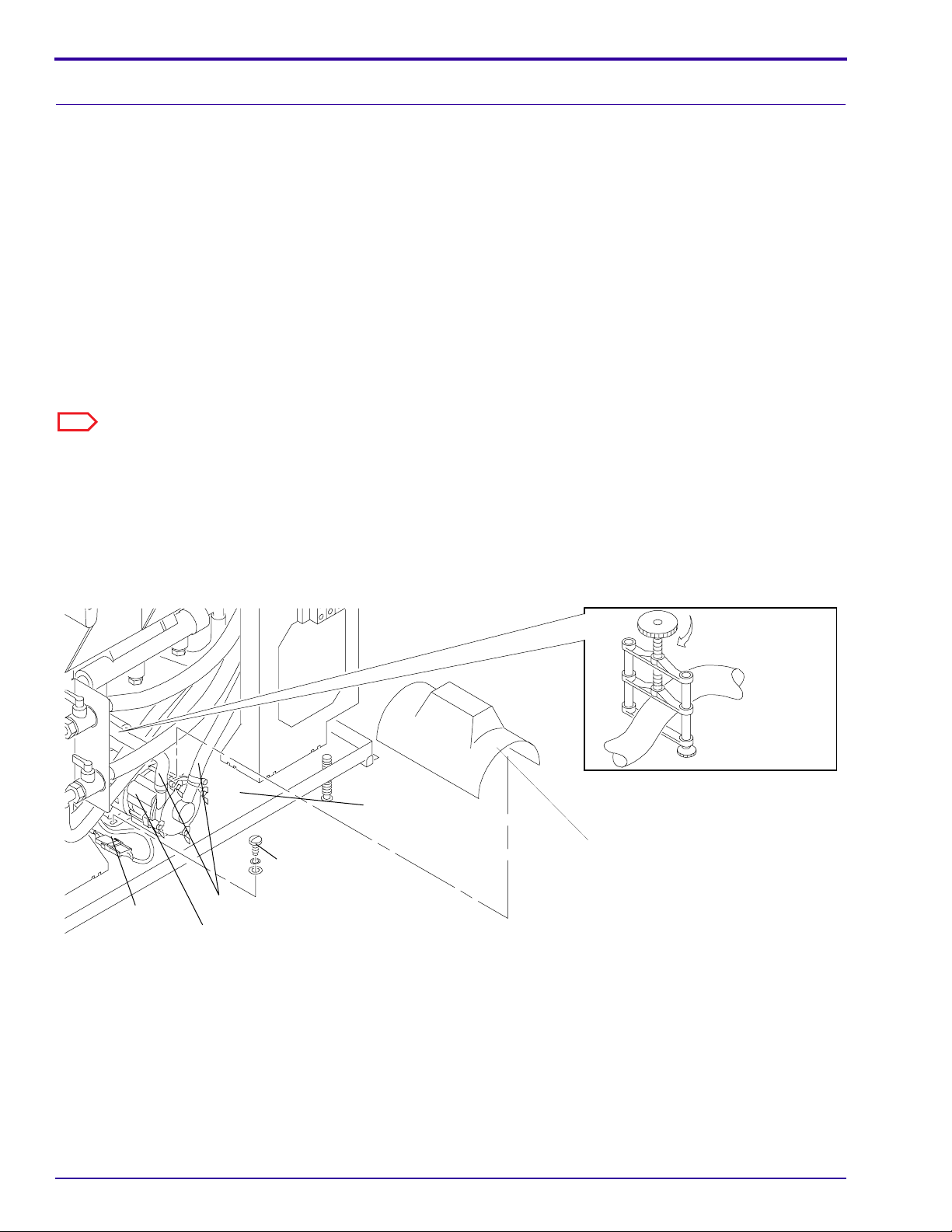
Removing the RECIRCULATION PUMP B5
[1] Move the main wall CIRCUIT BREAKER to “OFF”and CB1 on the PROCESSOR to the “O” position.
[2] Lift the TOP COVER.
[3] Remove:
• DRYER SIDE PANEL
• DRIVE SIDE PANEL
• SPLASH COVER
[4] Open the ELECTRICAL BOX.
[5] Use 4 CLAMPS TL-2170 on the 2 DEVELOPER HOSES and the2 FIXER HOSES to the RECIRCULATION
PUMP.
[6] Loosen the 4 HOSE CLAMPS. Remove the 2 DEVELOPER HOSESand the 2 FIXER HOSES from the
RECIRCULATION PUMP.
Note
The 2 FIXER HOSES are not in the figure.
[7] Remove the 2 SCREWS that hold the RECIRCULATION PUMPto the BASE PLATE of the PROCESSOR.
[8] Disconnect CONNECTOR P/J12 for the RECIRCULATION PUMP.
[9] Remove the RECIRCULATION PUMP.
[10] Reverse the procedure to assemble.
Figure 5–1 Replacement of the RECIRCULATION PUMP
BASE
PLATE
2 SCREWS
CONNECTOR
P/J12
DEVELOPER
HOSES
RECIRCULATION PUMP
SPLASH
COVER
TL-2170
H127_0029BCA
H127_0029BA
5–2 February 1996 – 1C7837
Page 3
Plumbing
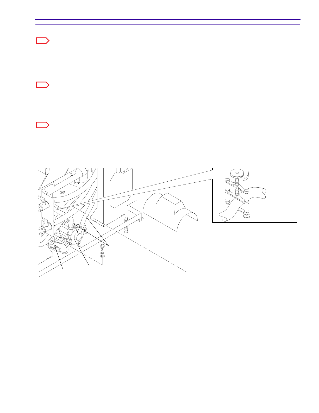
Removing the IMPELLER HOUSING or the IMPELLER
Note
Use this procedure for either the developer IMPELLERHOUSING or the fixer IMPELLER HOUSING.
[1] Move the main wall CIRCUIT BREAKER to “OFF”and CB1 on the PROCESSOR to the “O” position.
[2] Lift the TOP COVER.
[3] Remove the DRIVE SIDE PANEL.
Note
For improved access, remove the FEED SIDE PANELto remove the developer IMPELLER or the DRYER SIDE
PANEL to removethe fixer IMPELLER.
[4] Use 2 CLAMPS TL-2170 on the 2 DEVELOPER HOSES or the2 FIXER HOSES to the RECIRCULATION
PUMP.
Note
The 2 FIXER HOSES are not in the figure.
[5] Loosen the 2 HOSE CLAMPS and remove the 2 DEVELOPER HOSESor the 2 FIXER HOSES from the
IMPELLER HOUSING.
Figure 5–2 Installing CLAMPS on the HOSES tothe RECIRCULATION PUMP
CONNECTOR
P/J-12
IMPELLER
HOUSING
DEVELOPER
HOSES
TL-2170
H127_0029BCB
H127_0029BA
1C7837 – February 1996 5–3
Page 4
ADJUSTMENTS AND REPLACEMENTS
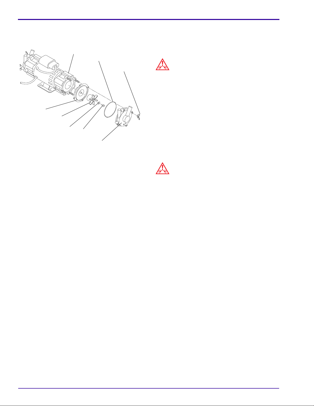
Figure 5–3 Replacement of the IMPELLERHOUSING
or the IMPELLER
RECIRCULATION
PUMP
O-RING
INNER
HOUSING
IMPELLER
WASHER
SCREW
IMPELLER
HOUSING
WING
NUT (4)
H104_0033ACB
H104_0033AA
[6] Remove:
• 4 WING NUTS from the IMPELLER
HOUSING
• IMPELLER HOUSING
Caution
To prevent chemical contamination, keep
theDEVELOPER and FIXER IMPELLERS and
IMPELLER HOUSINGS separate.
[7] Remove the INNER HOUSING from the
RECIRCULATION PUMP.
[8] To remove the IMPELLER from the INNER
HOUSING:
a. Remove the SCREW and WASHER from the
IMPELLER.
b. Remove the IMPELLER.
[9] Check the O-RING for wear. If necessary, install
a newO-RING.
Caution
To prevent leakage, the O-RING must be inthe correct
position.
[10] Check that the O-RING is correctly seated.
[11] Reverse the procedure to assemble.
[12] Tighten the SCREW.
[13] Check that the IMPELLER moves freely.
5–4 February 1996 – 1C7837
Page 5
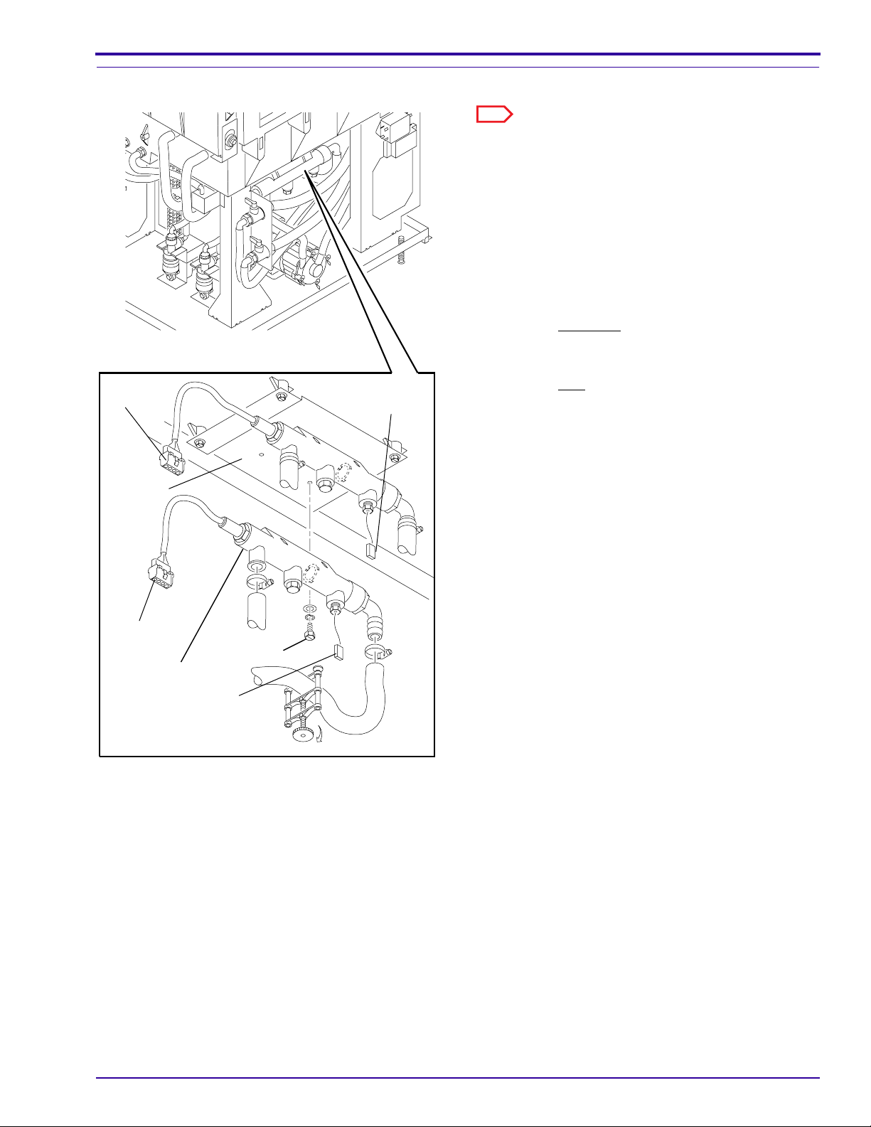
Removing the THERMOWELL
CONNECTOR
P/J20
MOUNTING
BASE
CONNECTOR
P/J26
Plumbing
Note
Use this procedure for either the developer orfixer
THERMOWELL.
[1] Move the main wall CIRCUIT BREAKER to
“OFF”and CB1 on the PROCESSOR to the “O”
position.
[2] Lift the TOP COVER.
[3] Remove the DRYER SIDE PANEL.
[4] Use 2 HOSE CLAMPS TL-2170 on the HOSES to
the THERMOWELL.
[5] For the developer, disconnectCONNECTORS P/
J20 and P/J26.for the developer or P/J19 for the
fixer.
[6] For the fixer, disconnect CONNECTORSP/J19
and P/J27.
[7] Loosen the 2 HOSE CLAMPS and remove the
HOSES.
[8] Remove the 2 SCREWS holding the
THERMOWELL to the MOUNTINGBASE.
[9] Remove the THERMOWELL.
[10] Reverse the procedure to assemble.
CONNECTOR
P/J19
THERMOWELL
CONNECTOR
P/J27
2 SCREWS
TL-2170
H127_0045CCA
H127_0045CA
1C7837 – February 1996 5–5
Page 6
ADJUSTMENTS AND REPLACEMENTS
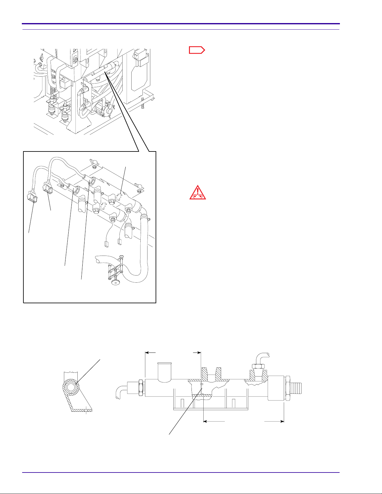
Removing the DEVELOPER or FIXER HEATER
LOCATING
RING
Note
Use this procedure for either the DEVELOPER
orFIXER HEATER.
[1] Move the main wall CIRCUIT BREAKER to
“OFF”and CB1 on the PROCESSOR to the “O”
position.
[2] Lift the TOP COVER.
[3] Remove the DRYER SIDE PANEL and the DRIVE
SIDE PANEL.
[4] Use 2 CLAMPS TL-2170 on the HOSES to the
THERMOWELL.
[5] Disconnect CONNECTOR P/J20 for the
developer or CONNECTORP/J19 for the fixer.
[6] Remove the DEVELOPER or FIXER HEATER
from the THERMOWELL.
Caution
CONNECTOR
P/J-20
CONNECTOR
P/J-19
FIXER
HEATER
DEVELOPER
HEATER
Figure 5–4 Replacement of the DEVELOPER or FIXERHEATER
TL-2170
HEATER
LOCATOR
H127_0050CCA
H127_0050CA
+
8.38 0.25 cm
+
(3.3 0.1 in)
-
[7] Check that the HEATER LOCATOR is in the
[8] Reverse the procedure to assemble.
[9] Check for leakage at the THERMOWELL.
• The internal HEATER LOCATOR must be in
thecorrect position in the THERMOWELL.
• Do not overtighten the parts during the
installation of theHEATER.
• Use SEALANT 1C8022 on the threads during
the installationof the HEATER into the
THERMOWELL. See the instructions
providedwith the SEALANT.
correct positionin the THERMOWELL.
+
13.9 0.25 cm
+
(5.5 0.1 in)
-
HEATER
LOCATOR
H104_0444BCA
H104_0444BA
5–6 February 1996 – 1C7837
Page 7

Removing the DEVELOPER or FIXER THERMISTOR
Use this procedure for either the DEVELOPER
orFIXER THERMISTOR.
[1] Move the main wall CIRCUIT BREAKER to
[2] Lift the TOP COVER.
[3] Remove the DRYER SIDE PANEL.
[4] Use 2 CLAMPS TL-2170 on the HOSES to the
[5] Disconnect CONNECTOR P/J26 for the
[6] Remove the THERMISTOR from the
DEVELOPER
THERMISTOR
Use SEALANT 1C8022 on the threads of
theTHERMISTOR for the installation of the
THERMISTOR into the THERMOWELL. See the
instructions provided with the SEALANT. Do not
overtightenthe parts during the installation of the
THERMISTOR.
FIXER THERMISTOR
CONNECTOR P/J-26
[7] Reverse the procedure to assemble.
[8] Check for leakage at the THERMOWELL.
Plumbing
Note
“OFF”and CB1 on the PROCESSOR to the “O”
position.
THERMOWELL.
developer or CONNECTORP/J27 for the fixer.
THERMOWELL.
Important
CONNECTOR P/J-27
TL-2170
H127_0050CCB
H127_0050CA
1C7837 – February 1996 5–7
Page 8

ADJUSTMENTS AND REPLACEMENTS
Removing the DEVELOPER FILTER
REPLENISHER
HOSE
[1] Move the main wall CIRCUIT BREAKER to
“OFF”and CB1 on the PROCESSOR to the “O”
position.
[2] Lift the TOP COVER.
[3] Remove the WET SECTION COVER and the
REPLENISHER HOSEfrom the MANDREL
ASSEMBLY.
MANDREL
ASSEMBLY
DEVELOPER
FILTER
WING NUT
LEVEL
SENSOR
HOUSING
Important
When removing the MANDREL ASSEMBLY, placea
DRIP TRAY under it to prevent contamination of the
FIXER.
[4] Rotate the MANDREL ASSEMBLY until the notch
in the topof the ASSEMBLY aligns with the LEVEL
SENSOR HOUSING CLIP on theLEVEL
SENSOR HOUSING.
[5] Remove the MANDREL ASSEMBLY by pulling
straight up.
[6] Remove:
• WING NUT from the MANDREL ASSEMBLY
• DEVELOPER FILTER from the MANDREL
ASSEMBLY
[7] Reverse the procedure to assemble.
[8] Install the MANDREL ASSEMBLY.
[9] Rotate the MANDREL ASSEMBLY until the
LEVEL SENSOR HOUSINGCLIP is in the locked
position.
H127_0135CCA
H127_0135CA
Figure 5–5 Replacement of the DEVELOPER FILTER
LEVEL SENSOR
HOUSING CLIP
H127_0061BCA
H127_0061BA
5–8 February 1996 – 1C7837
UNLOCKED
MANDREL
HOUSING
LOCKED
Page 9

Removing the LEVEL SENSOR HOUSING and LEVEL SENSORPROBES
H127_0153AA
H127_0153ACA
WASHER
GASKET SIDE
SCREW
TANK
PROBE
WIRE
Plumbing
MANDREL
ASSEMBLY
SCREW (2)
WASHER
REPLENISHER
HOSE
Note
Use this procedure for either the developer,red, or fixer,
blue, LEVEL SENSOR PROBES.
[1] Move the main wall CIRCUIT BREAKER to
“OFF”and CB1 on the PROCESSOR to the “O”
position.
[2] Lift the TOP COVER.
[3] Remove the WET SECTION COVER and the
NON-DRIVE SIDE PANEL.
[4] Remove the 2 SCREWS and the WASHER
located on the outsideof the TANK.
[5] Lift the LEVEL SENSOR HOUSING out.
[6] Remove the LEVEL SENSOR PROBE from the
LEVEL SENSOR HOUSING.
[7] Reverse the procedure to assemble.
[8] Check that the PROBE WIRE is correctly attached
to theSCREW and WASHER.
[9] Check that the WASHER is in the correct position
withthe GASKET SIDE of the WASHER against
the TANK. See Figure .
PROBE
WIRE
LEVEL SENSOR
HOUSING
LEVEL
SENSOR
PROBE
H127_0134CCA
H127_0134CA
Figure 5–6 Replacement of theLEVEL SENSOR
HOUSING and PROBES
1C7837 – February 1996 5–9
Page 10

ADJUSTMENTS AND REPLACEMENTS
Removing the DEVELOPER COOLING SOLENOID L2
[1] Move the main wall CIRCUIT BREAKER to “OFF”and CB1 on the PROCESSOR to the “O” position.
[2] Lift the TOP COVER.
[3] Remove the DRIVE SIDE PANEL.
[4] Move the ELECTRICAL BOX out.
[5] Use 2 CLAMPS TL-2170 on the 2 HOSES to the COOLING SOLENOID.
[6] Loosen the HOSE CLAMPS and remove the HOSES.
[7] Disconnect CONNECTOR P/J23 at the COOLING SOLENOID.
[8] Remove:
• 2 SCREWS holding the COOLING SOLENOID tothe MOUNTING BRACKET
• COOLING SOLENOID
Important
• When installing the COOLING SOLENOID, the“A” must be on the top and the “C”on the bottom.
• Use SEALANT 1C8022 on the threads of the FITTINGS during theinstallation of the FITTINGS into the new
COOLING SOLENOID. Seethe instructions provided with the SEALANT.
• Do not overtighten the parts during the installation of thefittings in the COOLING SOLENOID.
[9] Reverse the procedure to assemble.
[10] Check for leakage at the COOLING SOLENOID.
Figure 5–7 Replacement of the DEVELOPER COOLINGSOLENOID
COOLING
SOLENOID
CONNECTOR
P/J23
TL-2170
A
FITTINGS
A
H127_0046BCA
H127_0046BA
2 SCREWS
5–10 February 1996 – 1C7837
Page 11

Removing the HEAT EXCHANGER
Plumbing
EXIT RACK
CONNECTOR
P/J-33
DRYER RACK
[1] Move the main wall CIRCUIT BREAKER to “OFF”and CB1 on the PROCESSOR to the “O” position.
[2] Lift the TOP COVER.
[3] Remove the DRIVE SIDE PANEL and the WET SECTION COVER.
[4] Disconnect CONNECTOR P/J33.
[5] Remove the EXIT RACK and the DRYER RACK.
[6] Use 2 CLAMPS TL-2170 on the HEAT EXCHANGER FORMED TUBING.
[7] Remove the HOSE CLAMPS.
Figure 5–8 Installing the CLAMPS
H127_0136BCA
H127_0136BA
TL-2170
CLAMP (2)
HEAT
EXCHANGER
FORMED
H127_0048BCB
H127_0048BA
1C7837 – February 1996 5–11
TUBING
Page 12

ADJUSTMENTS AND REPLACEMENTS
Figure 5–9 Replacement of the HEAT EXCHANGER
HEAT
EXCHANGER
O-RING SEAL
[8] Remove:
• FORMED TUBING from the ends of the BARBEDFITTINGS
• BARBED FITTINGS from the HEAT EXCHANGER
• O-RING SEALS
• HEAT EXCHANGER from the WASH TANK
BARBED FITTING
HOSE CLAMP
FORMED TUBING
H127_0215HCA
H127_0215HA
5–12 February 1996 – 1C7837
Page 13

Figure 5–10 Aligning the Ends ofthe HEAT EXCHANGER
Plumbing
HEAT
EXCHANGER
O-RING SEAL
BARBED FITTING
HEAT
EXCHANGER
Caution
• Install new O-RING SEALS 532378. Do notuse the existing O-RING SEALS again.
• Do not overtighten the BARBED FITTINGS.
NOTE: Align the ends of
the HEAT EXCHANGER
flush with the ends of
the BARBED FITTINGS.
H127_0214BCA
H127_0214BA
[9] Reverse the procedure to assemble. Align the ends ofthe HEAT EXCHANGER flush with the ends of the
BARBED FITTINGS. See Figure 5–10.
1C7837 – February 1996 5–13
Page 14

ADJUSTMENTS AND REPLACEMENTS
Wash System
Removing the WATER SOLENOID VALVE L1
[1] Move the main wall CIRCUIT BREAKER to “OFF”and CB1 on the PROCESSOR to the “O” position.
[2] Turn off the main water supply.
[3] Lift the TOP COVER.
[4] Remove the DRIVE SIDE PANEL.
[5] Remove the 2 SCREWS from the WATER SOLENOID VALVE.
[6] Disconnect CONNECTOR P/J30 from the WATER SOLENOID VALVE.
Note
Disconnect the HOSES very slowly to release thepressure.
[7] Loosen the HOSE CLAMPS and remove the 2 HOSES from theWATER SOLENOID VALVE.
[8] Remove the WATER SOLENOID VALVE from the PROCESSOR.
[9] Reverse the procedure to assemble.
Important
Check for leakage at the WATER SOLENOIDVALVE.
2 SCREWS
H127_0137BCA
H127_0137BA
CONNECTOR
P/J30
WATER
SOLENOID
VALVE
5–14 February 1996 – 1C7837
Page 15

Plumbing
Replenishment System
Removing the REPLENISHER STRAINER ASSEMBLIES and SCREENS
[1] Move the main wall CIRCUIT BREAKER to “OFF”and CB1 on the PROCESSOR to the “O” position.
[2] Use 2 CLAMPS TL-2170 on the HOSES on either side of theREPLENISHER STRAINER.
[3] To remove the REPLENISHER STRAINER, loosen the 2 HOSECLAMPS and remove the REPLENISHER
STRAINER.
[4] Remove the CAP and the SCREEN from the REPLENISHER STRAINER.
[5] Clean the SCREEN or, if necessary, install a new SCREEN.
[6] Check the O-RING for wear. If necessary, install a newO-RING.
[7] Reverse the procedure to assemble.
Figure 5–11 Replacement of the REPENISHER STRAINERASSEMBLIES or the SCREENS
REPLENISHER
STRAINER
TL-2170
O-RING
CAP
SCREEN
H127_0030BCA
H127_0030BA
1C7837 – February 1996 5–15
Page 16

ADJUSTMENTS AND REPLACEMENTS
Removing the DEVELOPER or FIXER REPLENISHMENT PUMP
[1] Move the main wall CIRCUIT BREAKER to “OFF”and CB1 on the PROCESSOR to the “O” position.
[2] Lift the TOP COVER.
[3] Remove the DRIVE SIDE PANEL.
[4] Move the ELECTRICAL BOX out.
[5] Use 2 CLAMPS TL-2170 on the 2 HOSES at the FIXERor DEVELOPER REPLENISHMENT PUMP.
[6] Remove:
• 2 HOSES from the REPLENISHMENT PUMP
• 2 SCREWS from the PUMP
[7] Disconnect CONNECTOR P/J15 for the developer or P/J16for the fixer.
[8] Remove the FIXER or DEVELOPER REPLENISHMENT PUMP.
[9] Reverse the procedure to assemble.
[10] Record the J number of the CONNECTORon the tag that is on the new DEVELOPER REPLENISHMENT
PUMP.
Figure 5–12 Replacement of a REPLENISHMENT PUMP
TL-2170
H127_0031BCA
H127_0031BA
ELECTRICAL
BOX
2 SCREWS
FIXER
REPLENISHMENT
PUMP
DEVELOPER
REPLENISHMENT
PUMP
5–16 February 1996 – 1C7837
Page 17

Plumbing
Removing the POPPET VALVES for the REPLENISHMENT PUMPS
[1] Move the main wall CIRCUIT BREAKER to “OFF”and CB1 on the PROCESSOR to the “O” position.
[2] Lift the TOP COVER.
[3] Remove the DRIVE SIDE PANEL.
[4] Move the ELECTRICAL BOX out.
[5] Use 2 CLAMPS TL-2170 on the 2 HOSES at the FIXERor DEVELOPER REPLENISHMENT PUMP.
[6] Remove the 2 HOSES from the FIXER or DEVELOPER REPLENISHMENTPUMP.
[7] Remove the FITTINGS from the VALVE body and the O-RINGS.
Note
Observe the direction of the POPPET VALVES beforeremoving them.
[8] Remove the POPPET VALVES.
[9] Check that the O-RINGS are seated correctly and thatthe POPPET VALVES and FITTINGS are in the correct
positions in theVALVE BODY. See Figure .
[10] Reverse the procedure to assemble.
Figure 5–13 Replacement of thePOPPET VALVES in the REPLENISHMENT PUMPS
FITTINGS
VALVE
BODY
H127_0033BCA
H127_0033BA
O-RINGS
POPPET
VALVES
1C7837 – February 1996 5–17
Page 18

ADJUSTMENTS AND REPLACEMENTS
5–18 February 1996 – 1C7837
 Loading...