

Page 1

Prostar
Archive Processor 220-240 V
Prostar
Archive Processor 120 V
Operator’s Manual
A-62051
Part No. 2E8257
Page 2
Safety
User Precautions
• Place the processor on a sturdy, level work surface capable of supporting 63.5 kg (140 lbs) and a table height between 53 cm
(21 in.) and 68 cm (27 in.).
• Make sure the electrical power outlet is located within 1.52 meters (5 feet) of the processor and is easily accessible.
• Use only the power cord(s) that was provided with the processor. Using any other power cord may cause electrical shock
and/or damage the product.
• Be sure the power cord is securely plugged into the wall outlet. Failure to do so may cause electrical shock or fire.
• Do not damage, knot, cut or modify the power cord. This may cause electrical shock or fire.
• The scanner requires a dedicated power outlet. Do not use an extension cord or power strip with the scanner.
• Do not connect the processor to an extension cord of multi-plug power strip. Use a dedicated power outlet.
• Leave sufficient space around the power outlet so it can be easily unplugged in case of an emergency.
• Do not use the processor if it becomes inordinately hot, has a strange odor, emits smoke, or makes unfamiliar noises.
Immediately stop the processor and disconnect the power cord from the power outlet. Contact Kodak Service.
• Follow the Kodak recommended maintenance and cleaning procedures.
• Material Safety Data Sheets (MSDS) are available on the Kodak website at: www.kodak.com/go/msds. When accessing the
MSDSs from the website, you will be required to provide the catalog number of the consumable you want the Material Safety
Data Sheet for. See the section entitled, “Supplies and consumables” later in this guide for supplies and catalog numbers.
• For disposal or recycling information, contact your local authorities, or in the USA, visit the Electronics Industry Alliance
website: www.eiae.org.
CAUTION: Moving parts, avoid contact.
CAUTION: Hot surface, avoid contact
Acoustic emission
Maschinenlärminformationsverordnung – 3, GSGV
Der arbeitsplatzbezogene Emissionswert beträgt <70 db(A).
[Machine Noise Information Ordinance — 3, GSGV
The operator-position noise emission value is <70 dB(A).]
EMC statements
United States: This equipment has been tested and found to comply with the limits for a Class A digital device pursuant to Part
15 of the FCC rules. These limits are designed to provide reasonable protection against harmful interference when the
equipment is operated in a commercial environment. This equipment generates, uses, and can radiate radio frequency energy
and, if not installed and used in accordance with the instruction manual, may cause harmful interference to radio
communications. Operation of this equipment in a residential area is likely to cause harmful interference in which case the user
will be required to correct the interference at his own expense.
European Union: WARNING: This is a Class A product. In a domestic environment this product may cause radio interference in
which case the user may be required to take adequate measures.
Japan: This is a Class A product based on the standard of the V oluntary Control Council for interference by information
Technology Equipment (VCCI). If this is used in a domestic environment, radio disturbance may arise. When such trouble
occurs, the user may be required to take corrective actions.
Page 3
Taiwan: WARNING: This is a Class A product. In a domestic environment this product may cause radio interference in which
声明,该产
此为A级产品,在生活环境中品可能会造成无线电干扰。在这种情况下,可能需要
用户对其干扰采取切实可行的措施
case the user may be required to take adequate measures.
Peoples Republic of China: WARNING: This is a Class A product. In a domestic environment this product may cause radio
interference in which case the user may be required to take adequate measures.
Korean: Please note that this equipment has obtained EMC registration for commercial use. In the event that it has been
mistakenly sold or purchased, please exchange it for equipment certified for home use.
Page 4

Contents
Introduction . . . . . . . . . . . . . . . . . . . . . . . . . . . . . . . . . . . . . . . . . . . . . . . . . . . . 1
Specifications. . . . . . . . . . . . . . . . . . . . . . . . . . . . . . . . . . . . . . . . . . . . . . . . . . . 2
Archive Processor Overview . . . . . . . . . . . . . . . . . . . . . . . . . . . . . . . . . . . . . . 4
Front . . . . . . . . . . . . . . . . . . . . . . . . . . . . . . . . . . . . . . . . . . . . . . . . . . . . . . 4
Rear . . . . . . . . . . . . . . . . . . . . . . . . . . . . . . . . . . . . . . . . . . . . . . . . . . . . . . . 5
Start-up Procedures. . . . . . . . . . . . . . . . . . . . . . . . . . . . . . . . . . . . . . . . . . . . . . 6
Daily start-up . . . . . . . . . . . . . . . . . . . . . . . . . . . . . . . . . . . . . . . . . . . . . . . . 6
Uncovering the processing section . . . . . . . . . . . . . . . . . . . . . . . . . . . . . 6
Filling the fixer tanks . . . . . . . . . . . . . . . . . . . . . . . . . . . . . . . . . . . . . . . . 7
Filling the developer tank. . . . . . . . . . . . . . . . . . . . . . . . . . . . . . . . . . . . . 8
Installing the processing racks. . . . . . . . . . . . . . . . . . . . . . . . . . . . . . . . . 9
Installing the dryer rack . . . . . . . . . . . . . . . . . . . . . . . . . . . . . . . . . . . . . . 9
Adjusting the inlet water temperature . . . . . . . . . . . . . . . . . . . . . . . . . . 10
Adjusting the developer temperature control. . . . . . . . . . . . . . . . . . . . . .11
Checking the dryer temperature . . . . . . . . . . . . . . . . . . . . . . . . . . . . . . 13
Checking the film transport . . . . . . . . . . . . . . . . . . . . . . . . . . . . . . . . . . 14
Operating the Archive Processor. . . . . . . . . . . . . . . . . . . . . . . . . . . . . . . . . . 15
Attaching film to a take-up reel. . . . . . . . . . . . . . . . . . . . . . . . . . . . . . . . . . 15
Using a trailer holder . . . . . . . . . . . . . . . . . . . . . . . . . . . . . . . . . . . . . . . 15
Looping the film . . . . . . . . . . . . . . . . . . . . . . . . . . . . . . . . . . . . . . . . . . . 16
When to start processing . . . . . . . . . . . . . . . . . . . . . . . . . . . . . . . . . . . . . . 17
Single-strand processing . . . . . . . . . . . . . . . . . . . . . . . . . . . . . . . . . . . . . . 17
Dual-strand processing . . . . . . . . . . . . . . . . . . . . . . . . . . . . . . . . . . . . . . . 21
Replenishing the Archive Processor . . . . . . . . . . . . . . . . . . . . . . . . . . . . . . . 26
Replenishment tables. . . . . . . . . . . . . . . . . . . . . . . . . . . . . . . . . . . . . . . . . 26
Mixed film sizes . . . . . . . . . . . . . . . . . . . . . . . . . . . . . . . . . . . . . . . . . . . 26
Changing chemicals during processing . . . . . . . . . . . . . . . . . . . . . . . . . . . 26
Replenishment unit. . . . . . . . . . . . . . . . . . . . . . . . . . . . . . . . . . . . . . . . . . . 28
Maintenance . . . . . . . . . . . . . . . . . . . . . . . . . . . . . . . . . . . . . . . . . . . . . . . . . . . 29
Cleaning the Archive Processor (daily) . . . . . . . . . . . . . . . . . . . . . . . . . . . 29
Cleaning the Archive Processor (periodic cleaning). . . . . . . . . . . . . . . . . . 31
Cleaning the developer racks and tank . . . . . . . . . . . . . . . . . . . . . . . . . . . 31
Cleaning the fixer racks, wash racks, and fixer tanks. . . . . . . . . . . . . . . . . 33
Cleaning the air filter . . . . . . . . . . . . . . . . . . . . . . . . . . . . . . . . . . . . . . . . . 34
Troubleshooting. . . . . . . . . . . . . . . . . . . . . . . . . . . . . . . . . . . . . . . . . . . . . . . . 35
Clearing a film jam . . . . . . . . . . . . . . . . . . . . . . . . . . . . . . . . . . . . . . . . . . . 35
Troubleshooting chart. . . . . . . . . . . . . . . . . . . . . . . . . . . . . . . . . . . . . . . . . 36
Accessories and Supplies. . . . . . . . . . . . . . . . . . . . . . . . . . . . . . . . . . . . . . . . 38
New Equipment Warranty . . . . . . . . . . . . . . . . . . . . . . . . . . . . . . . . . . . . . . . . 40
For installations in the United States . . . . . . . . . . . . . . . . . . . . . . . . . . . . . 40
For installations outside the United States . . . . . . . . . . . . . . . . . . . . . . . . . 41
A-62051 May 2008 i
Page 5
Introduction
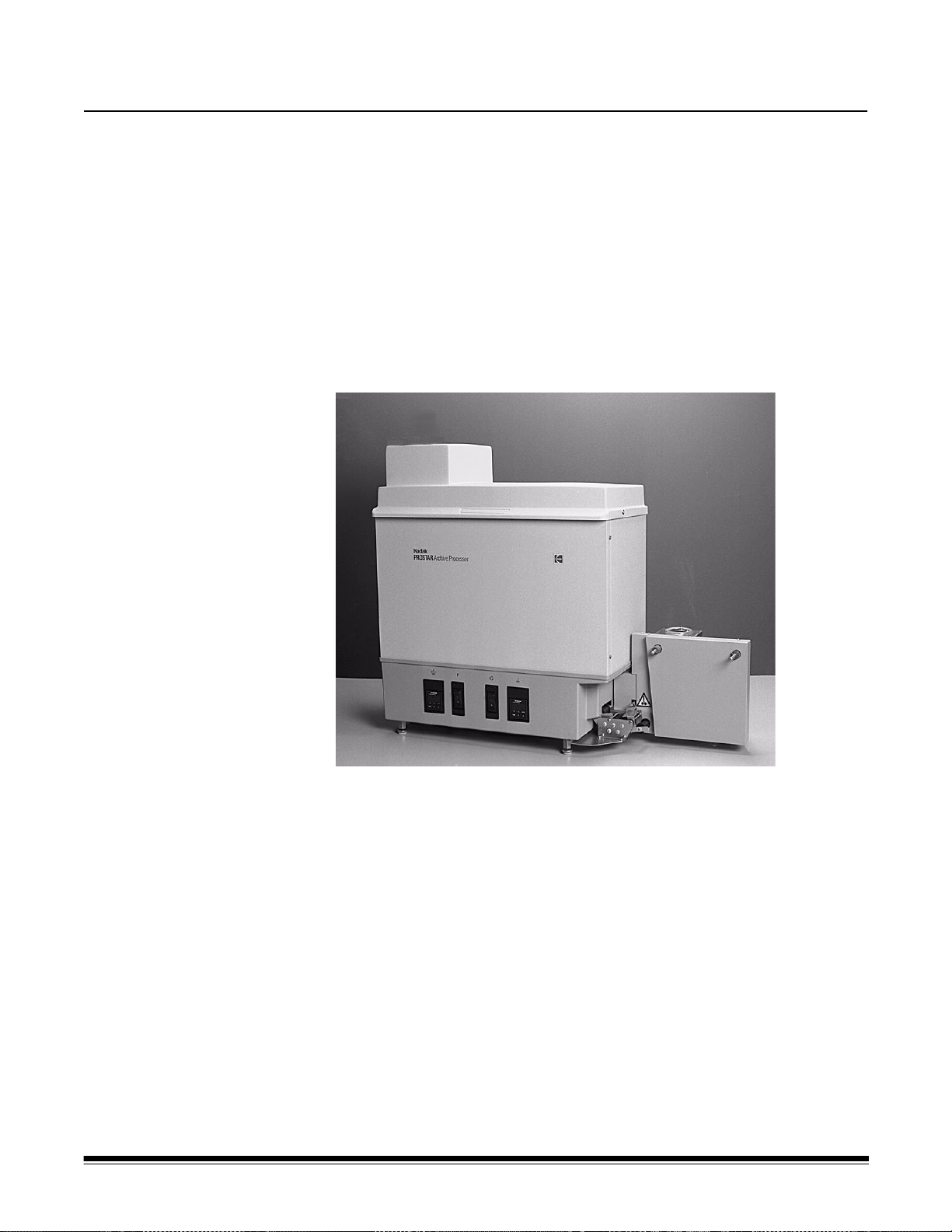
The Kodak Prostar Archive Processor 220-240 V and the Kodak
Prostar Archive Processor 120 V are room-light-loading processors that
process 16 mm and 35 mm silver halide microfilms with Kodak Prostar
Chemicals (or equivalent).
The Archive Processors are self-threading, tabletop units with roller
transport.
The Archive Processors feature an energy conservation package that
automatically turns off the film transport, rinse water, and film drying
system after processing is complete.
Kodak Prostar Archive Processor with dual-strand take-up spindles
A-62051 May 2008 1
Page 6

Specifications
Archive Processor 220-240 V Archive Processor 120 V
Power
requirements
Dimensions and
weight
220 to 240 VAC, 50 Hz, single phase,
7.5 amp
Two-prong electrical plug with ground
connection
Height: 91 cm (36 in.) with the cover open
Length: 110 cm (43 in.) with reel on take-up
spindle
120 VAC, 50 Hz, single phase, 12 amp
120 VAC, 60 Hz, single phase, 12 amp
Three-prong electrical plug with ground
connection
Height: 91 cm (36 in.) with the cover open
Length: 99 cm (39 in.) without reel on
take-up spindle
Operating
environment
Heat emissions
Noise emission
Depth: 56 cm (22 in.) with the cover open
Weight: 52.2 kg (1 15 Ib) empty
63.5 kg (140 Ib) with chemicals,
water, and processing racks
Support: Table or stand between
53 and 68 cm (21 and 27 in.) high
Ambient Temperature: 18.5 to 30°C
(65 to 86°F)
Relative Humidity: 20 to 76%
Maximum: 5100 BTU (5380 Kjoules)
Standby: 350 BTU (366 Kjoules)
Processing Film: 4100 BTU (4325 Kjoules)
Operator Position Standby Mode
• Sound Pressure Level (L
Operator Position Full System
Operating Mode
• Sound Pressure Level (L
• Instantaneous Peak Values 130 dB(C):
None
• Sound Power Level (L
• Standby: 63.4 dB(A)
• Full System: 69.6 dB(A)
): 51.2 dB(A)
A
): 59.3 dB(A)
A
)
WA
110 cm (43 in.) with large reel on
take-up spindle
Depth 61 cm (24 in.) with the cover open
Weight: 52.2 kg (115 Ib) empty
63.5 kg (140 Ib) with chemicals,
water, and processing racks
Support: Table or stand between
53 and 68 cm (21 and 27 in.) high
Ambient Temperature: 18.5 to 30°C
(65 to 86°F)
Relative Humidity: 20 to 76%
Maximum: 5100 BTU (5380 Kjoules)
Standby: 350 BTU (366 Kjoules)
Processing Film: 4100 BTU (4325 Kjoules)
Operator Position Standby Mode
• Sound Pressure Level (L
Operator Position Full System
Operating Mode
• Sound Pressure Level (L
• Instantaneous Peak Values 130 dB(C):
None
Sound Power Level (L
• Standby: 63.4 dB(A)
• Full System: 69.6 dB(A)
): 51.2 dB(A)
A
): 59.3 dB(A)
A
)
WA
2 A-62051 May 2008
Page 7

Water supply
Archive Processor 220-240 V Archive Processor 120 V
NOTE: An auxiliary hot water heater should be located within 6 m (20 ft) of the
Archive Processor to provide consistent water temperature.
Film Widths
Film Lengths and
Thicknesses
Film Transport
Speed
Film Processing
Time
Process
Duration
Film Loading
To Mixing Valve:
• Hot Water 46°C (114°F) minimum
• Cold Water 24°C (75°F) maximum
Pressure 276 to 621 kPa (40 to 90 psi)
From Mixing Valve:
• Mixed Water 34.5 to 36.5°C (94 to 98°F)
• Pressure 207 kPa (30 psi) minimum
Drain: Minimum 22.7 L/min (6 gal/min)
capacity floor drain or wall drain located a
minimum of 20 cm (8 in.) lower than the
Archive Processor to prevent wash water from
backing up
Water Consumption: 1.9 L/min (0.5 gal/min)
while processing
16 mm or 35 mm single strand
16 mm dual strand in lengths up to 65.5 m
(215 ft)
30.5 m (100 ft) of 0.14 mm/5.2 mil-thick film
38.1 m (125 ft) of 0.11 mm/4.2 mil-thick film
65.5 m (215 ft) of 0.07 mm/2.7 mil-thick film
3 m/min. (10 ft/min) 3 m/min. (10 ft/min)
30.5 m (100 ft): 11 minutes
65.5 m (215 ft): 22.5 minutes
Approximately 55 seconds for the selfthreader to exit from the Archive Processor
Room-light conditions with camera film spools
only
To Mixing Valve:
• Hot Water 46°C (114°F) minimum
• Cold Water 24°C (75°F) maximum
• Pressure 276 to 621 kPa (40 to 90 psi)
From Mixing Valve:
• Mixed Water 34.5 to 36.5°C (94 to 98°F)
• Pressure 207 kPa (30 psi) minimum
Drain: Minimum 22.7 L/min (6 gal/min)
capacity floor drain or wall drain located a
minimum of 20 cm (8 in.) lower than the
Archive Processor to prevent wash water from
backing up
Water Consumption: 1.9 L/min (0.5 gal/min)
while processing
16 mm or 35 mm single strand
16 mm dual strand in lengths up to 65.5 m
(215 ft)
30.5 m (100 ft) of 0.14 mm/5.2 mil-thick film
38.1 m (125 ft) of 0.11 mm/4.2 mil-thick film
65.5 m (215 ft) of 0.07 mm/2.7 mil-thick film
30.5 m (100 ft): 11 minutes
65.5 m (215 ft): 22.5 minutes
Approximately 55 seconds for the selfthreader to exit from the Archive Processor
Room-light conditions with camera film spools
A-62051 May 2008 3
Page 8
Archive Processor Overview
A
BC DE
G
F
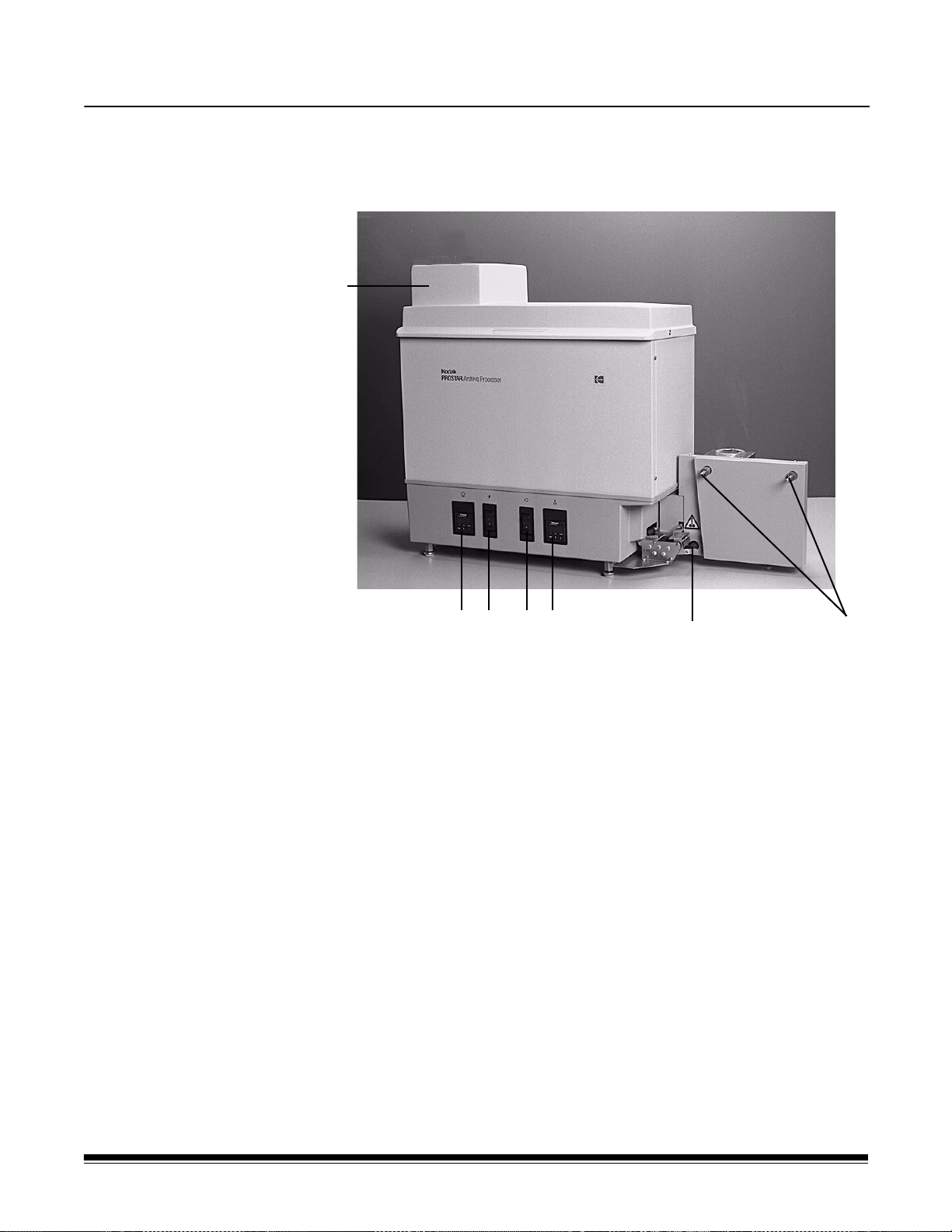
Front Shown throughout this manual is an Archive Processor equipped with
Dual-Strand Take-up Spindles
A Processing Section Cover — light-tight cover for the film
processing section.
B Developer Temperature Control and Display — controls the
developer temperature and displays a value relative to the water
temperature surrounding the developer tank.
C Power Switch — turns the power on (l) and off (O).
D Mode Switch — the standby position (O) maintains the developer
temperature. The run position (l) activates the film transport, rinse
water, and film dryer blower.
E Film Dryer Temperature Control and Display — controls the
dryer air temperature and displays the air temperature in the drying
chamber.
F Tension Roller — loss of film tension after processing causes the
tension roller to be released, initiating a time delay prior to
activating energy conservation mode. Once energy conservation is
activated, the film transport, rinse water, and film dryer blower will
all turn off.
G Take-Up Spindles — mechanisms that wind the processed film
onto the take-up reel.
4 A-62051 May 2008
Page 9
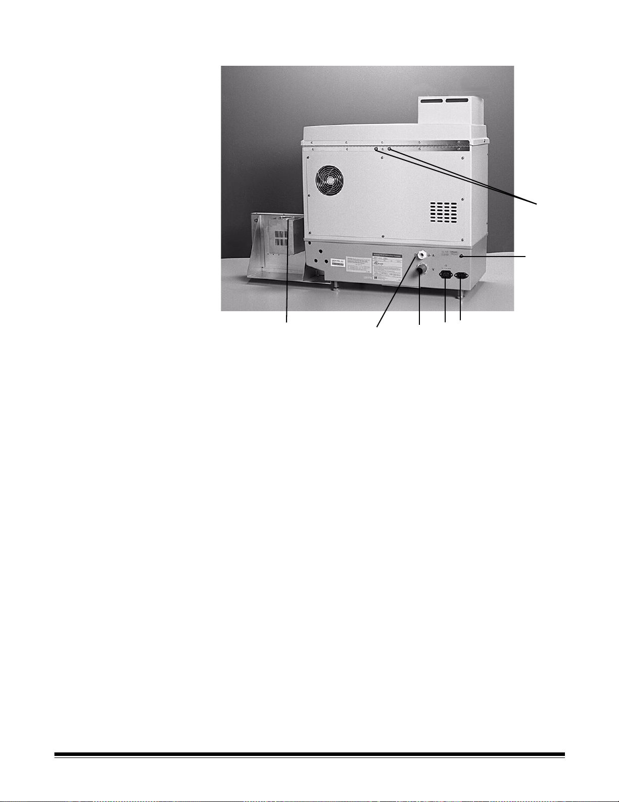
Rear
G
F
E
D
CB
A
A Usage Meter — displays the total number of hours the film
transport motors have been operating. You can use the usage
meter to determine when to change the processing chemicals.
B Water Inlet — connection to thermostatic mixing valve.
C Water Outlet — connection to drain line.
D Accessory Receptacle — supplies power to the optional
automatic Replenishment Unit accessory.
E Power Receptacle — connection for main power cord.
F Circuit Breaker — safety feature in case of electrical overload.
G Hose Input — connectors for the optional automatic
Replenishment Unit accessory hoses.
A-62051 May 2008 5
Page 10
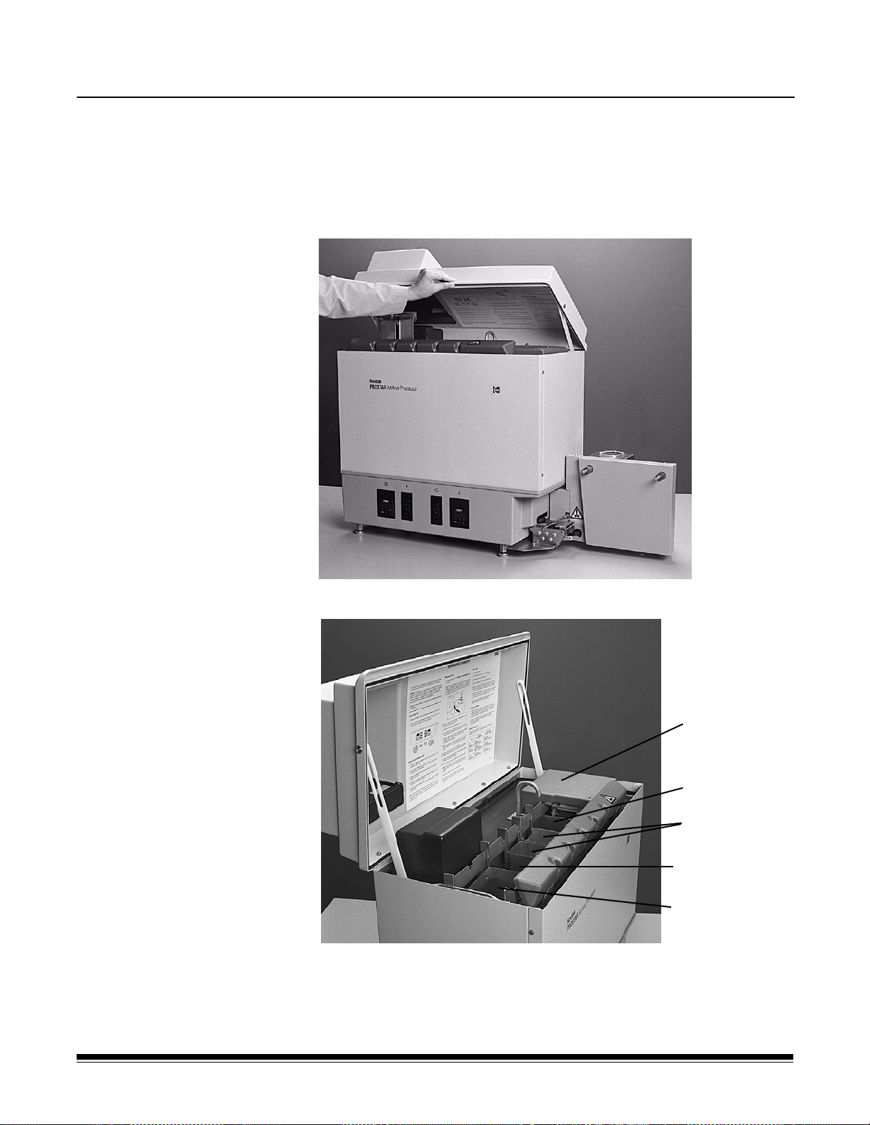
Start-up Procedures
Dryer Section
(Rack #7)
Wash (Rack #6)
Fixer Tanks
(Racks #4 and 5)
Wash (Rack #3)
Developer Tank
(Racks #1 and 2)
Daily start-up Follow these procedures when starting up the Archive Processor at the
beginning of the day, assuming that the Archive Processor was
properly shut down.
Uncovering the processing section
• Lift the processing section cover until it is in an upright position.
The inside of the Archive Processor is shown below without racks.
6 A-62051 May 2008
Page 11

Filling the fixer tanks If the Archive Processor is powered up, shut it off before you
remove the fixer tanks or turn off the water. This reduces the
possibility of water overflowing the water jacket later when you reinsert
the tanks.
NOTE: Use proper precautions when using fixer. Review the MSDS for
the fixer.
1. Pull the gear cover back and lift the fixer tanks out of the
Archive Processor. Each fixer tank is labeled with an F.
2. Fill the fixer tanks with Kodak Prostar Plus Fixer, or equivalent, until
the level reaches the fill line (approximately ¼ gallon or 0.65 liters
per tank).
3. Hold the gear cover back and slowly and carefully lower the fixer
tanks into the fourth and fifth position in the Archive Processor.
NOTE: Make sure that the tanks are fully seated and level with the
fill lines toward the rear of the Archive Processor.
A-62051 May 2008 7
Page 12

Filling the developer tank If the Archive Processor is powered up, shut it off before you remove
the developer tank or turn off the water. This prevents water from
overflowing the water jacket later when you reinsert the tank.
NOTE: Use proper precautions when using developer. Review the
MSDS for the developer.
1. Pull the gear cover back and lift the developer tank out of the
Archive Processor. The developer tank is labeled with a D.
2. Fill the developer tank with Kodak Prostar Plus Developer, or
equivalent, until the level reaches the fill line (approximately
½ gallon or 1.3 liters).
3. Wrap the overflow tubing closely around the right side of the
developer tank.
4. Hold the gear cover back and slowly and carefully lower the
developer tank into the first position in the Archive Processor.
NOTE: Make sure the tank is fully seated and level with the fill line
toward the rear of the Archive Processor.
5. Fill the squeeze bottle with developer.
The squeeze bottle will be needed later to top off the developer t ank
between processing rolls of film.
8 A-62051 May 2008
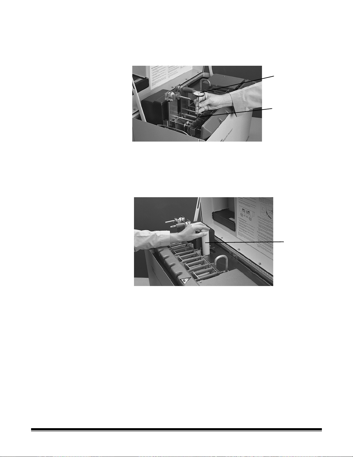
Page 13

Installing the processing
Rack #6
Gear Cover
Gear Cover
Dryer Rack (#7)
Dryer Section Cover
racks
1. Make sure that the rollers of each rack turn freely when you rotate
the drive gear.
2. Drain off any e xcess water if the ra cks were lef t submerged in water
since the last time film was processed.
3. Hold the gear cover back and lower the processing racks into the
processor (#6 rack first, then #5, #4, #3, #2, and #1).
The rack number is located just above the drive gear.
CAUTION: Lower the racks slowly and carefully into the
Archive Processor to avoid splashing any chemicals.
Installing the dryer rack 1. Lift off the dryer section cover.
2. Make sure that the rollers of the dryer rack turn freely when rotating
the drive gear.
3. Pull the gear cover back and lower the dryer rack into the dryer
section.
4. Replace the dryer section cover.
A-62051 May 2008 9
Page 14
Adjusting the inlet water
Thermometer
Thermometer
Sleeve
Standpipe
temperature
1. Turn on the water supply using the thermostatic mixing valve.
2. Turn the power switch to the On position.
3. Insert the thermometer in the thermometer fixed measuring point
sleeve located in the front right corner of the #1 rack.
4. Install the standpipe in the Archive Processor tank after the water
temperature, indicated on the mixing valve, reaches 34.5 to 36.5°C
(94 to 98°F).
Installing the standpipe after the water reaches the proper
temperature at the mixing valve enables the developer solution to
reach operating temperature sooner.
5. Route the tubing from the developer tank through the notch in the
partition.
6. Insert the tubing into the standpipe.
7. Allow the water jacket to fill up.
8. A float switch automatically turns off the water flow when the water
level is just below the top of the standpipe.
9. Close the processing section cover.
10.Allow approximately 25 minutes for the developer temperature to
stabilize before adjusting the temperature control setting.
10 A-62051 May 2008
Page 15
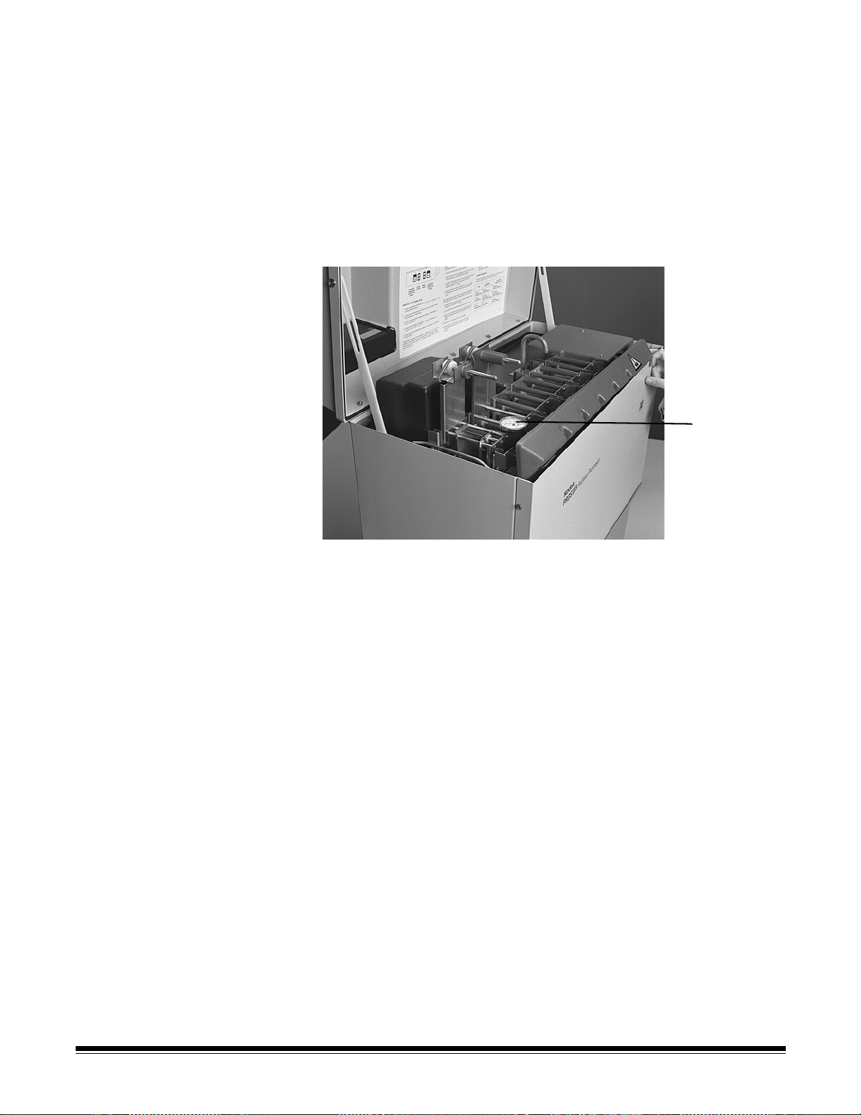
Adjusting the developer
Thermometer
temperature control
The Archive Processor’s developer temperature control is factory set to
a value of 88.0 to control the developer temperature at 37.8°C ±0.3°C
(100°F ±0.5°F). The display values and setpoint value are arbitrary
numbers and do not represent the temperature in degrees; they are
values relative to the developer temperature.
Reading the developer temperature
The developer temperature must be read on the dial thermometer.
1. Lift the processing section cover.
2. Locate the dial thermometer in the front right corner of the #1 rack.
3. Read the value on the thermometer.
If the developer temperature thermometer value is not 37.8°C
±0.3°C (100°F ±0.5°F), you must make an adjustment. Adjust the
developer temperature control setpoint value only if necessary.
Refer to the next section, “Changing the developer temperature
control setpoint value.”
4. Close the processing section cover.
A-62051 May 2008 11
Page 16

Changing the developer temperature control setpoint value
The developer temperature control is located on the left side of the
control panel.
1. Press and release the PGM button on the developer temperature
control.
The light to the left of the SP (setpoint) illuminates. The control is
now in the setpoint mode.
2. Change the developer temperature:
• Push and release the down arrow to lower the temperature.
• Push and release the up arrow to raise the temperature.
The amount of change to the setpoint is equal to the amount of
change to the developer temperature in degrees Celsius. For
example, increasing the developer temperature setpoint by 1.2 will
increase the developer temperature by approximately 1.2°C
(2.2°F).
To increase or decrease the developer temperature by 1°F,
increase or decrease the developer temperature setpoint by 0.56.
For each degree Fahrenheit (°F) of desired change, multiply by 0.56
and round to the nearest tenth.
For example, if the dial thermometer reads 98.5°F, an increase of
1.5°F is required to obtain 100°F. Multiply 1.5°F by 0.56 and you get
0.84
(1.5 x 0.56 = 0.84). Round 0.84 to the nearest tenth to get 0.8.
Therefore, to increase the developer temperature 1.5°F, you must
increase the developer temperature setpoint by 0.8.
3.Press and release the PGM button on the developer temperature
control to return to display mode.
The green light indicator to the left of the SP is no longer
illuminated. The current temperature is displayed.
The green light indictor illuminates when the temperature is at
the setpoint and flashes when the temperature is above the
setpoint. The light does not illuminate when the temperature
is below the setpoint.
This light can be used to determine when the temperature has
stabilized at the setpoint.
4. Wait 20 minutes between adjustments.
5. Lift up the processing section cover.
6. Read the developer temperature. If the temperature is not 37.8°C
±0.3°C (100°F ±0.5°F), repeat steps 1 through 6 until the
temperature stabilizes at the setpoint.
7. Close the processing section cover.
12 A-62051 May 2008
Page 17

Checking the dryer temperature
1. Turn on the drying heater and blower:
• If the water jacket is not full, fill the water jacket and press and
release the Mode switch to the Run position.
• If the water jacket is full, press and release the Mode switch to
the Run position.
2. Check the temperature reading on the dryer contr ol after it stab ilizes
(approximately 5 minutes).
If the drying temperature stabilizes (the displayed value stops
climbing) before it reaches the setpoint, the room temperature may
be too low or the specified setpoint is too high for the
Archive Processor to obtain. The green light will be off. (See
Operating Environment in the “Specifications” section.)
The Archive Processor is stabilized at the setpoint when the display
temperature cycles (decreasing, then increasing) and the indicator
light cycles (on, flashing, off).
3. Adjust the dryer temperature control (if necessary) so the dryer
temperature falls within the acceptable temperature range of 38 to
52°C (100 to 125°F).
Under most operating environments, a setting of 48°C (118°F) is
sufficient for proper drying. If the processor is operated in a high
temperature and high humidity environment, a setting as high as
52°C (125°F) may be required.
Adjusting the dryer temperature
1. Press and release the PGM button on the dryer control (located on
the right side of the control panel).
The light to the left of the SP (setpoint) illuminates. The control is
now in the setpoint mode.
2. Change the dryer temperature:
• Push and release the down arrow to lower the temperature.
• Push and release the up arrow to raise the temperature.
3. The amount of change to the setpoint is equal to the amount of
change to the dryer temperature.
For example, increasing the dryer temperature setpoint by 5 will
increase the dryer temperature by 5°C on the Archive Processor
220-240 V or 5°F on the Archive Processor 120 V.
NOTE: The Field Engineer can change the control readout to either
Fahrenheit (°F) or Celsius (°C).
A-62051 May 2008 13
Page 18

4. Press and release the PGM button on the dryer control to return to
display mode. The light to the left of the SP (setpoint) is no longer
illuminated. The current temperature is displayed.
5. Allow some time for the dryer chamber temperature to st abilize af ter
each adjustment (approximately 5 minutes).
NOTE: Film must feel dry to the touch. If the dryer temperature is too
high, film could stick to the rollers and cause a film jam. Also, a
temperature setting that is too high can cause the film to stick
together on the reel (bricking).
If the dryer temperature is too low, the film will not dry
completely, causing it to feel tacky when it exits and stick
together on the take-up reel.
Image quality defects will occur if the temperature setting is
too low or too high.
6. Turn the dryer and the transport off by lifting and releasing the
tension roller.
The dryer and transport will stop after a preset time delay has
elapsed. (The factory preset is 60 seconds. The Field Engineer can
change the time delay.)
Checking the film transport 1. Press and release the Mode switch to the Run position.
2. Feed a self-threader into the feed chute on the #1 rack to make sure
that all racks are fully seated and working properly. Allow the selfthreader to exit the processor.
3. Lift and release the tension roller to shut off the processor. The
processor will stop 60 seconds after the tension roller is released.
14 A-62051 May 2008
Page 19

Operating the Archive Processor
Film
Film Reel
Trailer Holder
Slot
Attaching film to a take-up reel
Using a trailer holder 1. Wrap the film counterclockwise around a trailer holder (snubber).
As processed film exits the Archive Processor, you must attach it to a
take-up reel. There are different ways to attach film to a take-up reel,
depending on the type of reel you are using. One way is to use a trailer
holder (snubber). Another way is to wrap the film around the center of
the reel. Both ways are described in this section.
NOTE: Kodak no longer supplies this reel with a separate trailer hold.
Kodak supplies only the integral film cinch pin as shown below.
2. Wrap the film around the trailer holder one more time.
3. Insert the trailer holder (snubber) in the core of the take-up reel.
4. Insert the film in the slot of the take-up reel.
A-62051 May 2008 15
Page 20
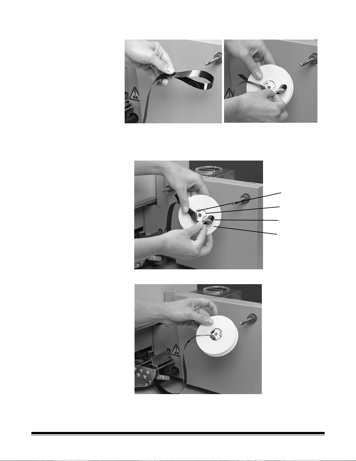
Looping the film 1. Make a loop of film about four inches long.
Pin
Slot
Film
Film Reel
2. Insert the film loop in the slot of the take-up reel.
3. Push the film around core of the take-up reel and wrap the loop
around the pin in the center of the take-up reel.
4. Pull the film gently to tighten it around the take-up reel.
16 A-62051 May 2008
Page 21

When to start processing
When the developer, film dryer, and water have reached their
acceptable operating temperatures, you may begin processing film.
Leave the dial thermometer in the developer tank; this makes it easier
to check the developer temperature before processing the next roll.
NOTE: When the Archive Processor is idle for an extended period, the
solutions may evaporate. Check the solution levels and
replenish the developer and fixer tanks as necessary.
Use the usage meter as a guide to changing chemicals. It displays the
number of hours the film drive system has run. Replace the developer
and fixer with fresh chemicals according to the frequency listed in
“Replenishing the Archive Processor,” or every two weeks, whichever
interval comes first.
NOTE: Do not restrict the movement of the tension roller. The tension
roller must be allowed to pivot freely for proper operation of the
Archive Processor.
Single-strand processing
Make sure that you have completed all of the procedures in the “Daily
start-up” section and that you have familiarized yourself with the
information in the “When to start processing” section before beginning
processing.
NOTE: To prevent film jams, remove as much curl from the self-
threader as possible by winding the self-threader in the opposite
direction from the existing curl.
1. Press and release the Mode switch to the Run position to pre-heat
the film dryer.
IMPORTANT: Always press and release the Mode switch to the Run
position, even if the transport is running. This prevents
the film transport from stopping during processing.
2. Lift the processing section cover.
3. Verify that the developer is at the proper level and add developer, if
necessary.
A-62051 May 2008 17
Page 22

To replenish the developer, place the neck of the squeeze bottle in
the developer tank and squeeze the bottle until the solution level
reaches above the middle of the first white roller located below the
feed chute.
4. Open the film box and remove the roll of exposed film.
NOTE: Do not let the film unwind.
IMPORTANT: Follow the next steps carefully to avoid film jams.
5. Using the reel flanges to guide you, line up a 16 mm self-threader (a
special leader that helps prevent film jams) with the film edges.
6. Slide the self-threader, with the black side up, under the leading
edge of the film and hold it in place with your index finger.
The film should overlap the self-threader by a minimum of 51 mm
(2 in.) with the emulsion (light-colored) side of the film contacting
the black side of the self-threader.
7. Fasten the leading end of the film to the self-threader using a
minimum of 76 mm (3 in.) of Kodak Prostar Tape, or equivalent.
NOTE: For 35 mm film, place several pieces of tape side-by-side to
fasten the leading edge of the film to the self-threader.
18 A-62051 May 2008
Page 23

8. Wind the self-threader onto the film reel.
Feed Chute
NOTE: Make sure the tape does not extend over the edges of the
film or self-threader. Avoid leaving fingerprints on the
adhesive side of the tape.
9. Verify that the temperatures of the developer, film dryer, and water
are all within specification.
NOTE: Under normal operating conditions, the dryer will have
reached the operating temperature by the time you have
attached the self-threader.
If there is high humidity, low temperature, or low line
voltage, the dryer may take longer to reach the acceptable
operating temperature. In these situations, you may want to
wait until all three operating temperatures are acceptable
before you attach the self-threader.
10.Place the roll of film on the supply spindle of the #1 rack so the film
unwinds off the right side of the reel (when you are facing the front
of the Archive Processor).
The emulsion (dull) side of the film and the gray side of the selfthreader both must face the left side of the Archive Processor.
11.Feed the self-threader down into the feed chute in the first
developer rack until the #1 rack starts to draw the self-threader into
the Archive Processor.
12.After the rollers draw the approximately 36 cm (14 in.) of the selfthreader into the rack, close the processing section cover.
After approximately 50 seconds, the self-threader exits below the
tension roller on the take-up (right) side of the Archive Processor.
IMPORTANT: As the self-threader exits the dryer, make sure
that it does not catch on anything that will cause
the film to back up and jam in the processor.
13.Grasp and keep a slight tension on the self-threader while drawing it
out until the film appears.
A-62051 May 2008 19
Page 24

14.Cut the film from the self-threader with a pair of scissors.
Take up Reel
Film
Tension Roller
15.Attach the film to a reel using one of the methods described in
“Attaching film to a take-up reel.”
16.Place the take-up reel on the spindle.
NOTE: If you pull on the self-threader or when you remove the self-
threader from the film, you may unintentionally raise and lower
the tension roller. Raising and lowering the tension roller
activates the time delay for energy conservation mode, which
causes the film transport to stop after 60 seconds (3 m or 10 ft
of film).
If approximately 2.5 m (8 ft) of film has exited from the
Archive Processor but has not yet been tensioned, lift and
release the tension roller to reset the time delay for an
additional 60 seconds.
If the film transport stops before the film is tensioned,
immediately press and release the Mode switch to the Run
position or lift and release the tension roller bracket. This will
restart the film transport. If film is left stopped in the processing
chemicals, image quality problems will result.
Remove all film ends and tape before reusing the selfthreaders. Do not use self-threaders that have been folded,
curled or shortened. Store the self-threaders by hanging them
from the prepunched hole in the end.
When the trailing end of the film leaves the dryer rack, tension is
lost and the tension roller automatically lowers. The loss of tension
activates the 60-second time delay for the energy conservation
mode. Once energy conservation mode is activated, the film
transport, rinse water, and dryer blower will all turn off.
17.Add developer to the developer tank if the Archive Processor
operates in manual replenishment mode.
Add developer after 61 m (200 ft) of 0.14 mm/5.2 mil-thick film or
65.5 m (215 ft) of 0.07 mm/2.7 mil-thick film has been processed.
20 A-62051 May 2008
Page 25

Dual-strand processing
If your Archive Processor is equipped with Dual-Strand Take-up
Spindles, follow the steps below to process two reels of film
simultaneously. Before processing, complete all of the procedures in
the “Daily start-up” section and familiarize yourself with the information
in the “When to start processing” section.
NOTE: To prevent film jams, remove as much curl from the self-
threader as possible by winding the self-threader in the opposite
direction from the existing curl.
1. Press and release the Mode switch to the Run position to pre-heat
the film dryer.
IMPORTANT: Always press and release the Mode switch to the Run
position, even if the transport is running. This prevents
the film transport from stopping during processing.
2. Lift the processing section cover.
3. Verify that the developer is at the proper level and add developer, if
necessary.
To replenish the developer, place the neck of the squeeze bottle in
the developer tank and squeeze the bottle until the solution level
reaches above the middle of the first white roller located below the
feed chute.
4. Open the film box and remove the roll of unexposed film.
NOTE: Do not let the film unwind.
IMPORTANT: Follow the next steps carefully to avoid film jams.
5. Using the reel flanges to guide yo u, line up the nar row end of a dualstrand self-threader (a special leader that helps prevent film jams)
with the film edges.
6. Slide the self-threader, with the black side up, under the leading
edge of the film and hold it in place with your index finger.
The film should overlap the self-threader by a minimum of 51 mm
(2 in.) with the emulsion (light-colored) side of the film contacting the
black side of the self-threader.
A-62051 May 2008 21
Page 26

7. Fasten the leading end of the film to the dual-strand self-threader
Self-threader
with a minimum of 76 mm (3 in.) of Kodak Prostar Tape, or
equivalent.
8. Wind the self-threader onto the film reel.
NOTE: Make sure the tape does not extend over the edges of the
film or self-threader. Avoid leaving fingerprints on the
adhesive side of the tape.
9. Verify that the temperatures of the developer, film dryer, and water
are all within specification.
NOTE: Under normal operating conditions, the dryer will have
reached the operating temperature by the time you have
attached the self-threader.
If there is high humidity, low temperature, or low line
voltage, the dryer may take longer to reach the acceptable
operating temperature. In these situations, you may want to
wait until all three operating temperatures are acceptable
before you attach the self-threader.
10.Place the roll of film on the supply spindle of the #1 rack so the film
unwinds off the right side of the reel (when you are facing the front
of the Archive Processor).
The emulsion (dull) side of the film and the gray side of the selfthreader both must face the left side of the Archive Processor.
11.Place the self-threader on top of the racks.
12.Load the second roll of microfilm on the spindle of the #2 developer
rack so that it unwinds from the right. Hold the film in place with your
index finger to prevent the film from unwinding.
22 A-62051 May 2008
Page 27

13.Place the film on top of the self-threader, overlapping it by 51 mm
Self-threader
Reel loaded
on second
spindle
Reel loaded
on first
spindle
(2 in.), and fasten the end of the film to the black side of the dualstrand self-threader with a minimum of 76 mm (3 in.) of Kodak
Prostar Tape, or equivalent.
14.Loop the leading edge of the self-threader to the left and beneath
the reels.
NOTE: Make sure the tape does not extend over the edges of the
film or self-threader.
15.Feed the self-threader down into the feed chute in the first
developer rack until the rack starts to draw the self-threa der into the
Archive Processor.
16.After the rollers draw all of the self-threader into the rack, close the
processing section cover.
After approximately 35 seconds, the self-threader exits below the
tension roller on the take-up (right) side of the Archive Processor.
IMPORTANT: As the self-threader exits the dryer, make sure that it
does not catch on anything that will cause the film to back
up and jam in the processor.
A-62051 May 2008 23
Page 28
17.Grasp and keep a slight tension on the self-threader while drawing it
The first film goes
on the reel closest
to the processor
out until the first film appears.
18.Cut the first film from the self-threader with a pair of scissors.
19.Attach the first film to a reel using one of the methods described in
“Attaching film to a take-up reel.”
20.Place the take-up reel on the spindle closest to the processor.
NOTE: If you pull on the self-threader or when you remove the self-
threader from the film, you may unintentionally raise and
lower the tension roller. Raising and lowering the tension
roller activates the time delay for energy conservation
mode, which causes the film transport to stop after 60
seconds (3 m or 10 ft of film).
If approximately 2.5 m (8 ft) of film has exited from the
Archive Processor but has not yet been tensioned, lift and
release the tension roller to reset the time delay for an
additional 60 seconds.
If the film transport stops before the film is tensioned,
immediately press and release the Mode switch to the run
position or lift and release the tension roller bracket. This
will restart the film transport. If film is left stopped in the
processing chemicals, image quality problems will result.
Remove all film ends and tape before reusing the selfthreaders. Do not use self-threaders that have been folded,
curled or shortened. Store the self-threaders by hanging
them from the prepunched hole in the end.
21.Continue to keep tension on the self-threader to keep the film
moving until the second film appears.
22.Cut the second film from the self-threader with a pair of scissors.
23.Attach the second film to a reel using one of the methods described
in “Attaching film to a take-up reel.”
24 A-62051 May 2008
Page 29

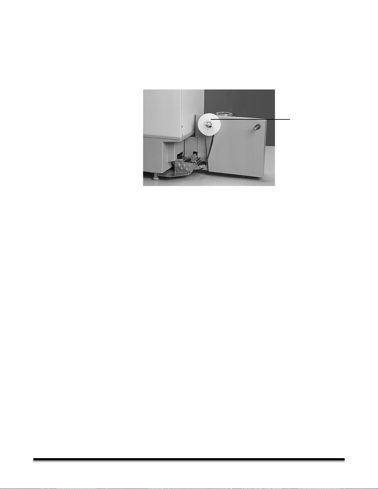
24.Insert the take-up reel onto the spindle farthest from the processor.
The second film goes
on the reel farthest
from the processor
When the trailing end of the film leaves the dryer rack, tension is
lost and the tension roller automatically lowers. The loss of tension
activates the 60-second time delay for the energy conservation
mode. Once energy conservation mode is activated, the film
transport, rinse water, and dryer blower will all turn off.
25.Add developer to the developer tank if the Archive Processor
operates in manual replenishment mode.
Add developer after 61 m (200 ft) of 0.14 mm/5.2 mil-thick film or
131 m (430 ft) of 0.07 mm/2.7 mil-thick film has been processed
while in dual-strand operation.
A-62051 May 2008 25
Page 30

Replenishing the Archive Processor
Replenishment tables Replace the developer and fixer with fresh chemicals according to the
frequency listed in the table below, or every two weeks, whichever
interval comes first.
NOTE: Change the developer and fixer at least every two weeks.
Film Manual Replenishment Automatic Replenishment
16 mm
single strand
16 mm
dual strand
35 mm
single strand
Mixed film sizes If you are processing both 16 mm and 35 mm film, use a combination of
the chemical replenishment guidelines. The chemical usage ratio for
35 mm to 16 mm film is 1:2.
5 hours
900 m (3000 ft)
2.5 hours
two strands of 450 m
(1500 ft) each
2.5 hours
450 m (1500 ft)
30 hours
5500 m (18,000 ft)
15 hours
two strands of 2750 m
(9000 ft) each
15 hours
2750 m (9000 ft)
Changing chemicals during processing
For example, with manual replenishment, you can process 457 m
(1500 ft) of 16 mm film and 230 m (750 ft) of 35 mm film before you
need to change the chemicals.
Use proper precautions when using processing chemicals. Review the
MSDS for the developer and fixer.
1. Power down the Archive Processor or turn off the water. This
reduces the possibility of the water jacket overflowing later when
you reinsert the tanks.
2. Hold the gear cover back and remove the processing racks from the
processor (#1 rack first, then #2, #3, #4, and #5).
The rack number is located just above the drive gear. Hold a
sponge under the racks when transferring them to the sink. This
avoids chemicals dripping on surrounding work areas or the floor
and possible cross-contamination of chemicals.
3. Pull the gear cover back and lift the fixer tanks out of the
Archive Processor. Each fixer tank is labeled with an F.
26 A-62051 May 2008
Page 31

4. Pull the gear cover back and lift the developer tank out of the
Archive Processor. The developer tank is labeled with a D.
5. Empty the developer tank.
6. Fill the developer tank with Kodak Prostar Plus Developer, or
equivalent, until the level reaches the fill line (approximately
½ gallon or 1.3 liters).
7. Wrap the overflow tubing closely around the right side of the
developer tank.
8. Hold the gear cover back and slowly and carefully lower the
developer tank into the first position in the Archive Processor.
NOTE: Make sure that the tank is fully seated and level with the fill
line toward the rear of the Archive Processor.
9. Route the tubing from the developer tank through the notch in the
partition.
10.Insert the tubing into the standpipe.
11.Empty the fixer tanks.
12.Fill the fixer tanks with Kodak Prostar Plus Fixer, or equivalent, until
the level reaches the fill line (approximately ¼ gallon or 0.65 liters
per tank).
13.Hold the gear cover back and slowly and carefully lower the fixer
tanks into the fourth and fifth position in the Archive Processor.
NOTE: Make sure the tanks are fully seated and level with the fill
line toward the rear of the Archive Processor.
14.Hold the gear cover back and lower the processing racks back into
the processor (#5 rack first, then #4, #3, #2, and #1).
The rack number is located just above the drive gear. Hold a
sponge under the racks when transferring them from the sink.
This avoids chemicals dripping on surrounding work areas or
the floor and possible cross-contamination of chemicals.
CAUTION: Lower the racks slowly and carefully into the
Archive Processor to avoid splashing any chemicals.
15.Close the processing section cover.
16.Power up the Archive Processor or turn the water on, depending on
the action that you performed in Step 1.
17.Allow approximately 25 minutes for the developer temperature to
stabilize before attempting to adjust the temperature control setting.
18.Press and release the Mode switch to the Run position.
19.Feed a self-threader into the feed chute on the #1 rack to make sure
that all racks are fully seated and working properly. Allow the selfthreader to exit the processor.
20.Lift and release the tension roller to shut off the processor. The
processor will stop 60 seconds after the tension roller is released.
A-62051 May 2008 27
Page 32

Replenishment unit If you prefer to use automatic replenishment rather than manual, you
must use the optional Kodak Prostar Replenishment Unit.
When using freshly mixed chemicals in the replenishment unit:
• 1300 ml (43.9 oz.) fills the tanks.
• The balance of the gallon (approximately 2400 ml) allows you to
process 915 m (3000 ft) of 16 mm microfilm.
• Each additional gallon (3785 ml) allows you to process 1525 m
(5000 ft) of 16 mm microfilm.
To avoid low film density resulting from low developer levels, change
the replenisher bottles when the solution level reaches the level
indicated in the operator's manual for the replenisher unit.
28 A-62051 May 2008
Page 33

Maintenance
Follow the recommended cleaning procedures to provide continued
quality film processing and reliable operation, and to extend the life of
the Archive Processor.
Cleaning the Archive Processor (daily)
At the end of each day's processing, clean the Archive Processor as
follows:
1. Turn off the water at the thermostatic mixing valve.
2. Turn the power switch to the Off position (O).
3. Lift the processing section cover.
4. Pull the standpipe out to drain the water jacket.
5. Hold the gear cover back and remove the processing racks from the
processor (#1 rack first, then #2, #3, #4, #5, and #6). The rack
number is located just above the drive gear. Hold a sponge under
the racks when transferring them to the sink. This avoids chemicals
dripping on surrounding work areas or the floor and possible crosscontamination of chemicals.
A-62051 May 2008 29
Page 34

6. Rinse the racks thoroughly in water while turning the drive gear.
7. Lightly rub the rollers with a clean cloth while rinsing to remove any
deposits from processing.
To remove difficult stains, use a nonabrasive cloth that will not
scratch the roller surface. Discoloration of the rollers is normal and
causes no harm.
8. Clean the developer racks (#1 and #2) thoroughly.
9. Leave the developer racks (#1 and #2) submerged in clean water
until they are needed.
Do not store the developer racks (#1 and #2) in the same water as
the fixer racks (#4 and #5).
CAUTION: When removing and rinsing the fixer racks (#4 and #5),
do not splash the developer racks with fixer or drip
fixer into the developer tanks.
Hold a sponge under the racks when transferring them
to the sink.
10.After thoroughly cleaning the remaining four processing racks, leave
them submerged in water until they are needed.
NOTE: Do not let the racks sit in water containing minerals that can
form a coating on the racks.
11.If the chemicals are exhausted, remove the developer and fixer
tanks, empty and rinse them out with water.
12.If the chemicals are not exhausted, the tanks can be left in the
Archive Processor.
13.Remove the dryer section cover and the dryer rack (#7).
14.Clean the dryer rack rollers with a clean, damp cloth. Do not rinse
the dryer rack with water.
15.Clean the recirculator cover, the area around the recirculator
assembly, and the drip tray with a damp sponge. Do not remove
the probe or pull out the wire from the recirculator.
16.Close the processing section cover and let the Archive Processor
stand as is until it is time to start it up again.
30 A-62051 May 2008
Page 35

Cleaning the Archive Processor (periodic cleaning)
Clean the developer racks with Kodak Developer System Cleaner and
Neutralizer, or equivalent, every time the chemical tanks are changed
using automatic replenishment (every third time with manual
replenishment) to remove silver and chemical deposits.
NOTE:Discharge, treatment, or disposal of spent solutions may
be subject to local, state, or federal laws. Contact
appropriate authorities to determine the requirements that
apply to the use of this product.
Cleaning the developer racks and tank
CAUTION: Follow the safe-handling instructions printed on the
bottle label.
1. Mix the Kodak System Cleaner.
• Start with 750 ml of water and add 125 ml of cleaner part “A”
concentrate and add 125 ml of cleaner part “B” concentrate then
mix until the solution is uniform.
or
• 6 parts of water add 1 p art of cleaner “A” and 1 part of clean er “B”
then mix until the solution is uniform.
NOTES:
• Do not mix developer system cleaner directly with neutralizer.
• Improper mixing and handling, such as allowing the cleaner to come
in contact with residual developer or the other processing solutions,
can form irritating sulfur dioxide fumes. Use adequate ventilation.
2. Mix neutralizer
• Start with 875 ml of water, add 125 ml of neutralizer concentrate
then mix until the solution is uniform
or
• 7 parts of water, add 1 part of neutralizer concentrate then mix
until uniform
3. Disconnect the power from the wall outlet.
4. Lift the processing section cover.
A-62051 May 2008 31
Page 36

5. Lift out the developer racks (#1 and #2).
6. Rinse the developer racks thoroughly with warm water.
7. Empty the developer tank and rinse the with warm water.
8. Fill the developer tank with mixed Kodak De veloper System Cleaner
“A” and “B” or equivalent, until the developer racks are covered,
then rotate the drive gears until the deposits are removed.
9. Allow a maximum of 30 minutes to clean heavily coated racks.
NOTE: Do not soak the racks longer than 30 minutes or at
temperatures above 32°C (90°F).
10.Remove the developer racks and rinse them thoroughly while
rotating the drive gears with warm water. There may be some
discoloration on the rollers; this is normal.
11.Empty the solution from the developer tank and rinse it with warm
water.
12.Pour the mixed neutralizer solution into the developer tank.
13.Place the developer racks into the neutralizer for 2 minutes.
14.Lift the developer racks out of neutralizer and wash them with warm
water.
Cleaning the fixer racks, wash racks, and fixer tanks
15.Empty the neutralizer from the developer tank and rinse it with warm
water.
NOTE: Do not use Kodak Developer System Cleaner and
Neutralizer on the fixer racks (#4 and #5) and wash racks
(#3 and #6) or on the dryer rack (#7). The daily
maintenance procedure is usually sufficient for these racks
(refer to “Cleaning the Archive Processor (daily)”). If
deposits have formed, refer to “Cleaning the fixer racks,
wash racks, and fixer tanks.”)
16.Close the processing section cover and let the Archive Processor
stand as is until it is time to start it up again.
1. Mix the Kodak Fixer/W ash System Cleaner , or equivalent, according
to the instructions on the bottle.
NOTE: If a smaller volume is needed, mix proportional amounts of
chemicals and water.
CAUTION: Follow the safe-handling instructions printed
on the label.
2. Lift out the fixer racks (#4 and #5) and the wash racks (#3 and #6).
3. Rinse the fixer racks and wash racks thoroughly with water and
place them in a plastic container .
4. Fill the plastic container with Kodak Fixer/Wash System Cleaner, or
equivalent, until the fixer racks and wash racks are covered. Soak
the racks until the deposits are removed.
32 A-62051 May 2008
Page 37

NOTE: Do not soak the racks longer than 30 minutes or at
temperatures above 38°C (100°F).
5. Remove the fixer racks and wash racks and rinse them thoroughly.
6. Place the fixer racks and wash racks in a container large enough to
hold them standing up and submerged; rinse them for at least 30
minutes in running water.
7. Soak the racks overnight in clean water.
8. Immerse the fixer tanks in the Kodak Fixer/Wash System Cleaner,
or equivalent.
9. Soak until the deposits have been removed.
10.Rinse the fixer tanks thoroughly with running water.
11.Close the processing section cover and let the Archive Processor
stand as is until it is time to start it up again.
A-62051 May 2008 33
Page 38

Changing the air filter Change the air filter every six months. The air filter is located under the
Air filter
Air filter housing
Archive Processor. It is accessible from the front of the processor.
1. Pull the air filter toward you and out of the air filter housing.
2. Hold a new air filter so that the air flow arrow on the edge of the filter
points up.
3. Slide the new air filter into the air filter housing.
34 A-62051 May 2008
Page 39

Troubleshooting
Clearing a film jam If a jam occurs either before or after the film is tensioned on the t ake-up
reel, follow the procedure below.
1. Turn the power switch to the off (O) position, and unplug the power
cord.
2. Lift the processing section cover.
3. Hold the supply spool to keep the film from unwinding.
4. Cut the film where it enters the first rack.
5. Remove the reel of film and immediately put it in the film box.
6. Lift off the dryer section cover.
7. In sequence, starting with the dryer rack, partially raise each rack
and cut the film where it enters the rack.
NOTE: Do not drip fixer from the fixer racks on the developer racks
or into the developer tank.
8. Lift each rack out of the Archive Processor and carefully pull the film
from the rack.
If film is wrapped around the rollers and cannot easily be pulled
from the rack, use scissors to carefully cut the film free from the
rollers. Remove all pieces of film from the rack.
NOTE: Do not scratch the rollers.
9. Thoroughly rinse all racks except the dryer rack and put them back
in the Archive Processor.
10.Turn the power switch to the On (l) position.
11.Press and release the Mode switch to the Run position.
12.Feed a self-threader through the Archive Processor two times to
check for further jamming problems.
13.If the self-threader exits from the Archive Processor without
problems, resume processing.
14.Lower the processing section cover.
A-62051 May 2008 35
Page 40

Troubleshooting chart
Problem Possible Cause Remedy
Archive Processor
does not power up
Film images are too
light or dark
Film jam
Power switch is set to the
Off (O) position
Main power supply is off Call a qualified electrician to check the power source.
Electrical plug is not firmly
connected in an outlet
or at the rear of the
Archive Processor
Circuit breaker is tripped Reset the circuit br ea ke r ( to lo ca te the circ uit br ea ke r, see
Incorrect developer
temperature
• Developer is exhausted
(light images)
• Developer tanks are not
filled to the correct level
(light images)
Self-threader is incorrectly
taped to the film
Turn the power switch to the On (l) position.
Check the electrical plug connection in the outlet and at
the rear of the Archive Processor.
the illustration at the top of Page 5).
• Adjust the thermostatic-mixing valve so that the incoming
water temperature is between 34 and 37°C
(94 and 98°F).
• Adjust the developer temperature control to a nominal
37.8°C (100°F).
Replenish the developer.
To replenish the developer, place the neck of the squeeze
bottle in the developer tank and squeeze the bottle until
the solution level reaches above the middle of the first
white roller located below the feed chute.
Clear the film jam (refer to “Clearing a film jam”). Reattach
or replace the self-threader (refer to “Operating the
Archive Processor”).
Self-threader is not
full length
Self-threader is damaged Clear the film jam (refer to “Clearing a film jam”). Replace
Self-threader is curled Clear the film jam (refer to “Clearing a film jam”). Reverse
Racks are not fully seated Clear the film jam (refer to “Clearing a film jam”). Check
Self-threader catches on
the table when exiting from
the Archive Processor
Film is loaded backward Clear the film jam (refer to “Clearing a film jam”). Place th e
Dryer chamber is too hot
Film is tacky, sticks to the
dryer rack
Clear the film jam (refer to “Clearing a film jam”). Replace
the self-threader (refer to “Operating the Archive
Processor”).
the self-threader (refer to “Operating the Archive
Processor”).
wind the self-threader until it lies flat (uncurled).
that all racks are properly seated and that all drive gears
are properly engaged.
Clear the film jam (refer to “Clearing a film jam”). Move the
Archive Processor toward the right edge of the t able so the
film clears the table edge.
film on the supply spindle so it unwinds from the right side
with the emulsion side (light color) of the film facing to the
left.
Refer to “Checking the dryer temperatur e.”
Clear the film jam (refer to “Clearing a film jam”).
Lower the dryer temperature.
36 A-62051 May 2008
Page 41

Troubleshooting Chart (continued)
Problem Possible Cause Remedy
Layers of film
(convolutions) stick
together on the
take-up reel
Film is scratched, has
digs or abrasions
Developer
temperature does not
reach 37.8°C in the
required 30 minutes
Self-threader
separates from the
film
Dryer chamber is not hot
enough to dry the film (film
feels damp)
Racks and tanks need
cleaning
Make sure that the trouble
is not caused by the
microfilming equipment in
which the film was exposed
Developer temperature
needs adjusting
Incorrect wash-water
temperature
Fingerprints on the
adhesive side of the
splicing tape
Adhesive tape is too short Reattach or replace the self-threader using a minimum of
Raise the dryer temperature.
Refer to “Maintenance.”
Adjust the developer temperature (refer to “Adjusting the
developer temperature control”).
Adjust the thermostatic mixing valve (refer to “Adjusting
the inlet water temperature”).
Reattach or replace the self-threader (refer to “Operating
the Archive Processor”). Avoid leaving fingerprints on the
adhesive side of the splicing tape.
76 mm (3 in.) of tape (refer to “Operating the
Archive Processor”).
Film quality is poor Chemicals are exhausted Change the chemicals.
Film stops before it is
tensioned on the
take-up reel.
Developer is contaminated
by system cleaner or fixer
The time delay of 60
seconds passed before the
film could be tensioned
Wash the racks and change the chemicals.
Train the operator to tension film in less than 60 seconds.
Lift the tension arm or press and release the Mode switch
to the Run position immediately to reset the 60-second
time delay for energy conservation mode (refer to
“Operating the Archive Processor”).
A-62051 May 2008 37
Page 42

Accessories and Supplies
Kodak Thermostatic Mixing Valve
Designed to control the water temperature to the
Archive Processor at a flowrate of 1.9 to 7.6 liters/
minute (0.5 to 2 gal/min).
Kodak Processor Cabinet
The top of the cabinet has space for the
Archive Processor and a chemical replenishing unit.
There is storage space inside the cabinet. The unit is
107 cm (42 in.) long, 64 cm (25 in.) deep, and 64 cm
(25 in.) high.
Kodak Prostar Replenishment Unit
Automatically replenishes the developer and fixer in
the Archive Processor.
Item Catalog
Number
142 3698
144 4256
809 0755
Supplies Catalog
Kodak Prostar Plus Developer 102 2490
Kodak Prostar Plus Fixer 102 2656
Kodak Developer System Cleaner and Neutralizer 150 0719
Kodak Fixer/Wash System Cleaner 139 5110
Kodak Solid Flange Return Reel (16 mm) case of 300 873 0715
Kodak Solid Flange Return Reel (35 mm) case of 150 144 2433
Microfilm Storage Carton, 16 mm case of 160 849 8966
Microfilm Storage Carton, 35 mm case of 80 841 8741
Kodak Prostar 16 mm Self-Threader 199 0993
Kodak Prostar 16 mm Dual-Strand Self-Threader 146 5194
Kodak Prostar 35 mm Self-Threader 199 1009
Kodak Prostar Tape and Dispenser 199 0977
Supplies Part Number
Kodak Prostar Air Filter 321984
Material Safety Data Sheets (MSDS) are available on the Kodak website at:
www.kodak.com/go/msds. When accessing the MSDSs from the website, you will be
required to provide the catalog number of the consumable you want the Material Safety
Data Sheet for. See the section entitled, “Supplies and consumables” later in this guide
for supplies and catalog numbers
Number
38 A-62051 May 2008
Page 43

New Equipment Warranty
For Installations in the United States
Kodak Prostar Archive Processor 120 V: Kodak warrants the
processor to function properly for three months from date of initial
installation, when installed within one year from date of shipment. This
warranty covers the purchaser of this equipment as well as anyone else
who owns it during the warranty period.
Warranty Repair Coverage: If this equipment does not function
properly during the warranty period, a Kodak Global Customer Service
and Support (GCSS) Field Engineer will provide on-site repair service
during Kodak’s normal working hours. Such repair service will include
any adjustments and/or replacement of parts ne cessary to maintain the
equipment in good working order. Off-hours service is available at
overtime rates.
Days and Hours of Coverage: Warranty coverage is available
Monday through Friday during Kodak’s normal working hours (usually
8:00 a.m. to 5:00 p.m.), excluding holidays celebrated locally.
How to Obtain Service: Call your nearest Kodak GCSS Office.
Limitations: Standard warranty service is limited to the contiguous
United States, the island of Oahu in Hawaii, and certain areas of
Alaska.
This warranty does not cover: circumstances beyond Kodak’s control;
service or parts to correct problems resulting from the use of
attachments, accessories, or alterations not marketed by Kodak;
service required as the result of relocation; unauthorized modifications
or service; misuse; abuse; failure to follow Kodak’s operating
instructions; or supply items (such as glass and lamps).
KODAK MAKES NO OTHER WARRANTIES, EXPRESS, IMPLIED,
OR OF MERCHANTABILITY OR FITNESS FOR A PARTICULAR
PURPOSE FOR THIS EQUIPMENT.
Repair or replacement without charge are Kodak’s only obligations
under this warranty . KODAK WILL NOT BE RESPONSIBLE FOR ANY
CONSEQUENTIAL OR INCIDENT AL DAMAGES RESULTING FROM
THE SALE, USE, OR IMPROPER FUNCTIONING OF THIS
EQUIPMENT, REGARDLESS OF THE CAUSE. Such damages for
which Kodak will not be responsible include, but are not limited to, loss
of revenue or profit, downtime costs, loss of use of the equipment, cost
of any substitute equipment, facilities, or services or claims of your
customers for such damages.
This limitation of liability will not apply to claims for injury to persons or
damage to property caused by the sole negligence or fault of Kodak or
by persons under its direction or control.
A-62051 May 2008 39
Page 44

For Installations outside the United States
For installation in countries other than the United States, the terms and
conditions of the new equipment warranty will be provided by the Kodak
company in the country in which the sale is finalized, or by a Kodakappointed distributor in those countries where Kodak does not have
direct sales representation.
40 A-62051 May 2008
Page 45

Eastman Kodak Company
343 State Street
Rochester, NY 14650 U.S.A.
© Kodak, 2008. All rights reserved.
TM: Kodak
 Loading...