

Page 1
KODAK PROFESSIONAL RP 50 LED Printer
Operator’s Guide Part No. 2J0686
Page 2

©Eastman Kodak Company, 2002
All rights reserved. Contents of this publication may not be reproduced in any form
without permission from Eastman Kodak Company.
Page 3
Regulatory Information
Radio Frequency Interference
The United States (47 CFR Part 15 Subpart B, FCC Class A, EMC)
This equipment has been tested and found to comply with the limits for a Class A
digital device, pursuant to Part 15 of the FCC Rules. These limits are designed to
provide reasonable protection against harmful interference when the equipment is
operated in a commercial environment. This equipment generates, uses, and can
radiate radio frequency energy and, if not installed and used in accordance with
the instruction manual, may cause harmful interference to radio communications.
Operation of this equipment in a residential area is likely to cause harmful
interference in which case the user will be required to correct the interference at
his own expense.
IMPORTANT:Changes or modifications to the product that are not authorized b y
Eastman Kodak Company could void the FCC Certification and
negate your authority to operate this product.
Canada (ICES-003 Issue 2 Rev1 Canada, Class A, EMC)
This Class A digital apparatus meets all requirements of the Canadian
Interference-Causing Eq uip men t Regula tio ns .
Cet appareil numerique de la classe A respecte toutes les exigences du
Reglement sur le materiel brouilleur du Canada.
European Union (EU, CE Marking, EMC)
This equipment has been type tested and found to comply with the requirements
for electromagnetic compatibility as established by European Communities
Council Directive 89/336/EEC and Low Voltage Directive (Product Safety)
73/23/EEC.
Japan (VCCI, Class 1 EMC)
The following is a translation of the above statement:
“This equipment is in the Class 1 category (information to be used in commercial
and/or industrial areas. Consequently, when used in a residential area or in an
adjacent area thereto, radio interference may be caused to radios and TV
receivers, etc. Read the instructions for correct handling”.
Page 4

Safety Regulations
IMPORT ANT : This equipment incorporates high-voltage components. Adequate safeguards and interlocks
have been designed into this equipment to reduce the risk of injury during normal operation.
As with any electrical equipment of this kind, adequate ventilation must be provided to
minimize exposure to heat, dust, ozone, and other emissions. The following labels will be
found on the product. The exclamation point symbol (A) indicates that the user should refer
to this guide for safety information. The hot symbol (B) indicates a hot surface area on the
printer that should not be touched. The electrical hazard/shock warning symbol (C)
identifies the possibility of electrical shock inside an area that should only be accessed by
Kodak CES personnel.
A B C
CAUTION: Before connecting or disconnecting the SCSI cable or terminator, turn off th e power
for the printer and the host computer. Also, if you replace the SCSI cable, remove the
Ferrite bead from the existing SCSI cable and install it on the new SCSI cable.
Page 5

Environmental Regulations
IMPORTANT: Always adhere to your local ordinances and regulations for disposal of paper, chemicals,
filters, cleaning supplies, etc.
Warranty Information
The following warranty inf or m at i on pertains to equipment that is in stalled i n th e Uni t ed States
only. For equipment installed in countries other than the United States, the terms and conditions
of the new equipment warranty will be provided by the Kodak company in the country in which
the sale is finalized, or by a Kod ak -appointed distributor in those countries where Kodak does
not have direct sales repr esentation.
Warranty Period
Kodak warrants new equipment to function properly fo r 90 days from the date of initial
installation. This warranty covers the purchaser of this equipment as well as anyone else who
owns it during the warrant y period.
Warranty Repair Coverage
If this equipment does not fu nct i on properly during the warra nt y period, a Kodak Custom er
Equipment Services Field Engineer will repair the equipment without charge during Kodak’s
normal working hours (us ua lly 8:00 a.m. to 5:00 p.m., Mond ay through Friday). Such repair
service will include any adjustments and/or replac ement of parts required to maintain yo ur
equipment in good work in g or der. Supply items are billed as required.
Off-hours services are avail able at overtime rates.
How to Obtain Service
For technical support, service, repair and fuse replacement information, contact Eastman Kodak
Company’s Technical Assistance Center at 1-800-822-1414.
Limitations
Warranty Service is limited to areas wi th in Kodak’s established marketing cen te rs in the
contiguous United States, the island of Oah u in H aw a ii, and certain areas of Alaska.
This warranty does not co ver circumstances beyond Kodak’s control; service or parts for any
attachments, accessories, or alt er at i ons not marketed by Kodak , no r to correct problems
resulting from their use.
Damaged caused by failure to meet electrical specifications in this manual will not be covered
under the warranty or servi ce agreement claim.
Damage to the imaging shoe as a result of customer misuse or abuse will not be covered under
the warranty or service agreement claim. Do no t us e sh ar p objects to clear paper in this area.
Kodak makes no other warranties, express, implied or of
merchantability, for this equipment.
Repair or replacement without charge is Kodak’s only obligation unde r this warranty. Kodak will
not be responsible for any consequential or incidental dam ages resulting from the sal e, us e or
improper functioning o f thi s eq ui pm ent, even if loss or damage is caused by the negligenc e or
other fault of Kodak.
Such damages, for which Kodak will not be responsible, include, but are not limited to, loss of
revenue of profit, downt i m e costs, loss of use of the equipm ent, cost of any substit ut e
equipment, facilities or services or claims of your customers for such damages.
Page 6

This limitation of liability will not apply to claims for injury to persons or damage to property
caused by the sole negli gence or fault of Kodak or by persons under its direction or co nt ro l.
Kodak Service Agreements
For information on Kodak Ser vice Agreements, call Kodak Serv ice M ar keting Operations
at 1-800-645-6325.
Page 7

Table of Contents
About This Guide..................................................................................................................................... xiii
Using This Guide................................................................................................................... xiv
About Other Publications ................................................ ....... ...... ....... ...... ....... ...... ....... ...... .. xiv
Software Included with the Printer ........................................................................................ xiv
Getting Help from Kodak........................................................................................................ xv
1 Introduction................................................................................................................................... ...... .. 1-1
Product Description............................................................................................................... 1-1
SCSI Interface ................................................................................................................ 1-1
KODAK PROFESSIONAL RP 50 LED Printer................................................................ 1-1
KODAK PROFESSIONAL Process or.............................. ...... ....... ...... ....... ...... ............... 1-2
Installation and Service .................................................................................................. 1-2
Equipment Overview............................................................................................................. 1-2
2 Using the System ......................................................................................................................... ...... .. 2-1
Starting up the Processor...................................................................................................... 2-1
Starting up the Printer ........................................................................................................... 2-2
Calibrating the Printer ........................................................................................................... 2-3
Obtaining Densities ........................................................................................................ 2-6
Obtaining Densities from a File ................................................................................2-6
Using the Densitometer to Read Densities ..............................................................2-6
Completing the Calibration ............................................................................................. 2-7
Making Prints ........................................................................................................................ 2-9
Shutting Down the Processor.... ...... ....... ...... ....... ...... ...... ....... ...... ....... ...... ....... ................... 2-10
Shutting Down the Printer .. ....... ...... ....... ...... ....... ...... ...... ....... ...... ....... ...... .......................... 2-11
3 System Operating Procedures ............................................................................................................. 3-1
Operating the Printer............................................................................................................. 3-2
Operator Control Panel.......................... ....... ...... ...... ....... ...... ....... ...... ....... ...... ....... ........ 3-2
OCP Key/Light Descriptions .....................................................................................3-3
Menu ........................................................................................................................3-4
Printer Offline Feature ..............................................................................................3-4
Cancelling Jobs ........................................................................................................3-4
Printing Deferred or Buffered Jobs................................................................................. 3-4
Status Messages............................................................................................................ 3-5
Loading Paper Into the Supply Cassette........................................................................ 3-6
Removing the Supply Cassette ................................................................................3-6
Loading Paper into the Supply Cassette ..................................................................3-7
Installing the Supply Cassette ........................................ ....... ...... ....... ...... ....... ...... .3-10
Reaching the End of the Roll of Paper ......................................................................... 3-13
Removing the Chad...................................................................................................... 3-14
Handling and Storing the Paper ................................................................................... 3-14
Storing Paper Using the Soft Shutdown Feature ...................................................3-14
October 2002 vii
Page 8

Accessing the Printer Features........................................................................................... 3-15
Shutdown and Restart .................................................................................................. 3-15
Shutdown ...............................................................................................................3-15
Restart ...................................... ............. ................... ................... .................... ....... 3-15
Unload Supply .............................................................................................................. 3-15
Selecting SCSI Ports .................................................................................................... 3-15
Selecting the Target Pad Read Options .................................................................3-16
Managing a Modem...................................................................................................... 3-16
Resetting the Modem Port .....................................................................................3-16
Checking for a Modem ...........................................................................................3-16
Setting the Printer Time and Date ................................................................................ 3-17
Setting the Current Time ........................................................................................3-17
Setting the Current Date ........................................................................................3-17
Setting the Current Day ..........................................................................................3-17
Setting the Paper Length.............................................................................................. 3-17
Selecting the Slug Width for the Paper......................................................................... 3-18
Setting the Page Starts Value ...................................................................................... 3-19
Producing Borderless Prints ...................................................................................3-20
Accessing the Software Version Number..................................................................... 3-22
Setting the Copyright Detection Feature ...................................................................... 3-22
Resetting the Defaults .................................................................................................. 3-23
Resetting the Parameters ......................................................................................3-23
Resetting the Printing LUTs ...................................................................................3-23
Resetting the Copyright Detection LUTs ................................................................3-23
Changing the Units of Measurement for Paper Sizes................................................... 3-24
About Printing........ ....... ...... ....... ...... ....... ...... ....... ...... ...... ....... ....................................... ...... 3-24
Image Size.................................................................................................................... 3-24
Buffered and Unbuffered Jobs (or Immediate and Deferred) ....................................... 3-24
Printing Deferred or Buffered Jobs .........................................................................3-25
Host Software Functions Supported by the Printer....................................................... 3-25
Bar Coding ........... ....... ...... ....... ...... ....... ...... ...... ....... ...... ....... ...... ....... .................... 3 -25
Pixel Doubling ........................................................................................................3-25
Operating the Processor ..................................................................................................... 3-26
Operator Control Panel................................................................................................. 3-26
View Mode .............................................................................................................3-26
Set Mode ................................................................................................................3-26
Calibrate Mode .......................................................................................................3-26
Min Max Mode ........................................................................................................3-26
OCP Key/Light Descriptions ...................................................................................3-27
Status Messages ....................................................................................................3-28
OCP On/Off Light ...................................................................................................3-29
Operational Modes ....................................................................................................... 3-30
Adjusting the Key Switch Lock ...............................................................................3-31
Processing a Control Strip............................................................................................ 3-32
Viewing/Setting the Processor Time and Date ............................................................. 3-33
Viewing the Current Time Setting ..........................................................................3-33
Setting the Current Time ........................................................................................3-33
Setting the Current Date ........................................................................................3-33
Viewing/Setting the Seven-Day Timer.......................................................................... 3-34
Viewing the On/Off Times ......................................................................................3-34
Setting the On/Off Times ........................................................................................3-34
Viewing the Software Identification............................................................................... 3-34
viii October 2002
Page 9

Viewing/Setting the Temperatures ............................................................................... 3-35
Viewing the Temperature Settings .........................................................................3-35
Setting the Temperature ........................................................................................3-35
Calibrating the Temperatures ....................................................................................... 3-35
Resetting the Min Max Temperatures........................................................................... 3-35
Viewing/Setting Replenishment Settings...................................................................... 3-36
Viewing the Replenishment Rate ...........................................................................3-36
Setting the Chemical Replenishment Rate ............................................................3-36
Setting the Wash Replenishment Rate ..................................................................3-36
Calibrating the Replenishment Flow Rate .................................................................... 3-36
Measuring the Flow Rate .......................................................................................3-36
Entering the Flow Rate ...........................................................................................3-37
Managing the Development Time................................................................................. 3-37
Viewing the Development Time .............................................................................3-37
Setting the Development Time ...............................................................................3-37
Calibrating the Development Time .........................................................................3-37
Displaying the Min Max Development Time ...........................................................3-38
Managing the Material Sensors.................................................................................... 3-38
Viewing the Material ................. ...... ....... ...... ...... ....................................... ....... ...... .3-38
Viewing the Processor Setup ............................ ....................................... ....... ...... .3-38
Selecting the Processor Setup .............................................. ...... ........................... 3 -38
Controlling the Processor Drive.................................................................................... 3-39
Turning the Drive On ..............................................................................................3-39
Returning the Drive to Normal Operation ...............................................................3-39
Computer Reset .... ...... ....... ...... ....... ...................................... ....... ...... ....... ...... ....... ...... 3-39
Resetting the Processor .........................................................................................3-39
Loading the Defaults and Changing the Configuration ..........................................3-39
Changing the Wash/Stabilizer Setup............................................................................ 3-40
Changing the Metric/Fahrenheit Mode ......................................................................... 3-40
Setting the Development Time Tolerance .................................................................... 3-41
Setting the Chemical Temperature Tolerance.............................................................. 3-41
Clearing Error Conditions ............................................................................................. 3-41
4 Maintaining the Equipment................................................................................................................... 4-1
Maintaining the Printer .......................................................................................................... 4-2
Daily Maintenance .......................................................................................................... 4-2
Removing the Chad .................................................................................................4-2
Calibrating the Printer ..............................................................................................4-2
Periodic Maintenance ..................................................................................................... 4-3
Replacing the Air Filter .............................................................................................4-3
Maintaining the Processor..................................................................................................... 4-4
Daily Maintenance .......................................................................................................... 4-4
Chemistry Levels ......................................................................................................4-4
Replenishment and Effluent Chemical Levels ..........................................................4-4
Cleaning the Crossover Assemblies ..................................... ...... ....... ...... ....... ...... ...4-5
Operational Checks ..................................................................................................4-6
Testing .....................................................................................................................4-6
October 2002 ix
Page 10

Weekly Maintenance ...................................................................................................... 4-7
Checking the Tension of the Main Drive Chain ........................................................4-7
Checking the Circulation ..........................................................................................4-7
Preventing Algae (for Wash Configuration) ..............................................................4-8
Cleaning the Crossover Assemblies and Transport Racks ......................................4-8
Cleaning the Feed Table and the Processor Entrance Sensors ..............................4-9
Replacing Chemical and Wash Filters ...................................................................4-10
Checking the Fittings for Leaks ..............................................................................4-10
Monthly Maintenance ............................ ....... ...... ...... ....... ...... ....... ...... ....... ...... ............. 4-11
Main Drive Chain ....................................................................................................4-11
Checking the Temperature of the Solutions ...........................................................4-11
Checking and Adjusting the Speed of the Processor .............................................4-11
Cleaning the Tank and Dryer Cover .......................................................................4-12
Periodic Maintenance ................................................................................................... 4-13
Cleaning Chemical Residue Buildup ........................................... ....... ...... ....... ...... .4-13
Cleaning the Processor Tanks .................... ...... ....... ...... ....... ...... ....... ...... ....... .......4-13
Adding New Chemistry ...........................................................................................4-14
Recommended Processor Settings.............................................................................. 4-15
5 Diagnostics and Troubleshooting ......................................................................................................... 5-1
Printer Error Messages ......................................................................................................... 5-2
Manual or Automatic Reinitialization............................................................................... 5-2
Printer Paper Path.................... ....... ...... ....... ...... ...... ....... ....................................... ...... .. 5-3
Printer Error Messages................................................................................................... 5-4
Miscellaneous Printer Error Messages......................................................................... 5-10
Clearing Printer Paper Jams ........................................................................................ 5-11
Troubleshooting Observable Errors.............................................................................. 5-12
Additional Troubleshooting Tips for the Printer............................................................. 5-15
Processor Error Messages.................................................................................................. 5-16
Clearing Error Messages.............................................................................................. 5-17
Clearing a Reset Message ........................................................................................... 5-17
Clearing Processor Paper Jams................................................................................... 5-18
Clearing Drive Errors.................................................................................................... 5-18
Additional Troubleshooting Tips for the Processor....................................................... 5-19
Calibration Troubleshooting ................................................................................................ 5-19
Calibration Graph ......................................................................................................... 5-19
Calibration Error Codes ................................................................................................ 5-20
Non-Numeric Error Messages ...................................................................................... 5-26
Getting Additional Help ....................................................................................................... 5-27
Appendix A: Ordering Supplies .............................................................................................................. A-1
Accessories.......................................................................................................................... A-1
Supplies ............................................................................................................................... A-1
Standard (U.S.) Paper.......................................................................................................... A-2
Metric Paper......................................................................................................................... A-2
Processor Chemicals ........................................................................................................... A-3
Publications.......................................................................................................................... A-3
x October 2002
Page 11

Appendix B: Specifications..................................................................................................................... B-1
Printer/Processor Specifications .......................................................................................... B-1
Dimensions and Weight................................................................................................. B-1
Acoustic Specifications.................................................................................................. B-1
Site Requirements................................................................................................................ B-2
Operator and Service Access.......................................... ....................................... ...... . B-2
Floor Requirements....................................................................................................... B-2
Plumbing........................................................................................................................ B-3
Electrical........................................................................................................................ B-4
Power Cords.................................................................................................................. B-5
Power Outlets................................................................................................................ B-5
Line Frequency.............................................................................................................. B-6
Power Receptacles (U.S. and Canada)......................................................................... B-6
Printer Power Receptacles (Europe) ............................................................................. B-7
Processor Power Receptacles (Europe)........................................................................ B-8
Line Voltage................................................................................................................... B-9
Operating Environment................................................................................................ B-10
Venting the Processor ........................................................................................... B-10
Processor Humidity Specifications .............................................................................. B-11
Wash Chemicals.......................................................................................................... B-11
Telephone line.................... ...... ....................................... ...... ....... ...... ....... ...... ....... ..... B-11
Densitometer ............................................................................................................... B-11
SCSI Cable.................................................................................................................. B-12
Appendix C: Additional Calibration Information ...................................................................................... C-1
Installing the Calibration Software ... ....... ...... ....... ...... ...... ....... ...... ....... ................................. C-1
System Requirements .............. ....... ...... ....... ...... ...... ....... ....................................... ...... . C-1
Installation Procedure.................................................................................................... C-2
Kodak Device Calibration Software...................................................................................... C-4
Application Window Definitions ..................................................................................... C-4
Starting the Kodak Device Calibration Software............................................................ C-6
Adding a Device ............................................................................................................ C-6
Editing the Log Settings................... ...... ....... ...... ...... ....... ...... ....... ...... ....... ...... ....... ....... C-8
Updating a Device ......................................................................................................... C-9
Deleting a Device ........................................................................................................ C-10
Advanced Features of the Calibration Software................................................................. C-11
Viewing Graphs ............................... ...... ....... ...... ...... ....................................... ....... ..... C-11
Sending LUTs. ....................................... ....... ...... ...... ....... ...... ....... ...... ....... ...... ....... ..... C-15
Sending Targets .............................. ...... ....... ...... ....................................... ...... ....... ..... C-17
Editing the Calibration Configuratio n ..................................... ....... ...... ....... ...... ....... ..... C-1 9
Editing Information on the Procedure Tab ............................................................C-22
Editing Information on the Density Source Tab ..................................................... C-24
Editing Information on the Aim Tab .......................................................................C-25
Editing Information on the History Tab ..................................................................C-26
Editing Information on the Paper Tab ....................................................................C-27
Editing Information on the DP2 (Windows NT) or KPIS (Macintosh) Tab .............C-27
Completing the Edit Configuration ........................................................................ C-31
Creating a Density File for Use with Calibration.......................................................... C-32
File Formats................................................................................................................. C-32
Installing the Densitometer........................... ....... ...................................... ....... ...... ....... ..... C-33
October 2002 xi
Page 12

Appendix D: Using the Image Print Server Software.............................................................................. D-1
Installing the IPS Software........................... ....... ...... ...... ....................................... ....... ...... . D-1
Hardware Requirements................................................................................................ D-1
Software Requirements............ ....... ...... ....... ...... ...... ....... ...... ....... ...... ....... .................... D-1
Installing the Software ..................... ...... ....... ...................................... ....... ...... ....... ...... . D-2
Using the Image Print Server............................................................................................... D-2
Inserting Images into the Print Queue........................................................................... D-2
Source Directory Insertion .......................................................................................D-2
Menu Bar Insertion ..................................................................................................D-2
Suspending and Resuming ........................................................................................... D-3
Failed Jobs .................................................................................................................... D-3
Attended Operation ....................................................................................................... D-3
Enqueue Example ......................................................................................................... D-4
Dialog Boxes and Print Options........................................................................................... D-6
Option Descriptions ....................................................................................................... D-7
Enqueue Dialog Box...................................................................................................... D-8
Option Descriptions .................................................................................................D-8
Source Directory Preferences Dialog Box..................................................................... D-9
Option Descriptions .................................................................................................D-9
Initialize Default Parameters Dialog Box ..................................................................... D-10
Description ............................................................................................................ D-10
File Format Details ...................................................................................................... D-10
Supported Tags........................................................................................................... D-10
LZW Compression....................................................................................................... D-10
Appendix E: Using the PHOTOSHOP Export Module............................................................................ E-1
Installing the Export Module...... ...... ....... ...... ....... ...... ...... ....... ...... ....... ................................. E-1
Hardware Requirements................................................................................................ E-1
Software Requirements............ ....... ...... ....... ...... ...... ....... ....................................... ...... . E-1
Installing the Software ..................... ...... ....... ...................................... ....... ...... ....... ...... . E-2
Printing Images .................................................................................................................... E-3
Dialog Boxes and Print Options........................................................................................... E-6
KODAK LED Main Dialog Box....................................................................................... E-6
Option Descriptions ................................................................................................. E-6
Other options ........................................................................................................... E-7
Punch Attributes ............................................................................................................ E-7
Option Descriptions ................................................................................................. E-7
Page Layout Attributes ................................................................................................. E-8
Option Descriptions ................................................................................................. E-8
Select an LED Printer Dialog Box.................................................................................. E-8
Option Descriptions ....................................................................................................... E-9
Printer Status Dialog Box .............................................................................................. E-9
Option Descriptions ..................................................................................................... E-10
Troubleshooting ................................................................................................................. E-10
Error messages ........................................................................................................... E-10
General error messages ....................................................................................... E-10
Other Problems ..................................................................................................... E-11
Index................................................................................................................................................ Index-1
xii October 2002
Page 13

This is an Operator’s Guide for the KODAK PROFESSIONAL RP 50 LED Printer
and Processor.
It provides step-by- step inst ructio ns for the operat ions you p erform wh ile usin g the
Printer and Processor as a system. It also includes procedures and information for
operating, maintaining, troubleshooting, and calibrating the system.
Also included in this guide are instructions for installing and using the various
software packages needed.
This guide is intended for personnel who operate this system. It assumes that you
can perform basic computer operations. MACINTOSH and
WINDOWS NT Platforms are supported in this guide.
This document also applies to the KODAK PROFESSIONAL LED II Printer 20P
and Processor.
Using This Guide
This guide is organized as follows:
Chapter 1 Introduction—describes and illustrates the K ODAK
About This Guide
PROFESSIONAL RP 50 LED Printer and Processor. This
chapter includes general and introductory information for all
of the equipment.
Chapter 2 Using the System—explains how to use the printer and
processor. It includes the step-by-step instructions for daily
operation, from startup to shutdown.
Chapter 3 System Operating Procedures—provides an overview of
the OCPs and all procedures for operating both the Printer
and the Processor.
Chapter 4 Maintaining the Equipment—includes the information that
you need to properly maintain the printer and processor. All
maintenance procedures are categorized by frequency.
Chapter 5 Diagnostics and Troubleshooting—provides an error
code listing, solutions to common operational problems for
the printer, processor and calibration. It also provides
information for obtaining additional help.
Appendix A Ordering Equipment, Accessories, and Supplies—
provides ordering information for many associated items. It
includes information such as size, quantities, and catalog
numbers.
October 2002 xiii
Page 14

About This Guide
Appendix B Specifications—provides specifications, site
requirements, and environmental information for the system.
Appendix C Calibrating the Printer—describes the calibration
functions for the KODAK Calibration Software and the
Printer Calibration Software.
Appendices D-F Software—explains how to install and use software that is
included with the system.
About Other Publications
The following publication is included with the printer:
Quick Reference Guide for the KODAK PROFESSIONAL RP 50 LED Printer
and Processor–provides quick and easily accessible information for operating
and maintaining the printer as well as answers to common printer problems and
hints for operating the processor. Keep the Quick Reference Guide close to your
printer.
Software Included with the Printer
The compact disc (CD) included with the KODAK PROFESSIONAL RP 50 LED
Printer contains the KODAK Calibration Software and the Printer Calibration
Software for WINDOWS NT and MACINTOSH Host Computers. It also includes
additional applications the printer can interface with.
This software is usually installed by a Kodak representative. However, installation
instructions are included in this Operator’s Guide.
A PDF file of this Operator’s Guide is also included on the CD.
You can find the latest software and documentation for the KODAK
PROFESSIONAL LED Printers on the Kodak Web site:
www.kodak.com.
xiv October 2002
Page 15

Getting Help from Kodak
Your Kodak sales representative is the best source for information about setting
up and operating your printer and for obtaining accessories and supplies. Please
contact your Kodak sales representative if you have any questions.
Kodak Sales Representative:___________________________
Representative’s Telephone Number: ____________________
K-Number: _________________________________________
In addition, for technical support in the U.S., call 1-800-822-1414 between
8:00 a.m. and 8:00 p.m. Eastern Standard Time on regular business days.
You can also use the technical support number for information on:
• operating the printer
• how or where to obtain supplies
• how to obtain service
• the warranty
• other Kodak products
About This Guide
If you are calling for technical support, please know your printer’s K-Number. The
K-Number label is attached to the front of the printer, next to the operator
control panel.
Product Literature
The faxback number for product literature is 1-800-508-1531. You may call this
number 7 days a week, 24 hours a day.
October 2002 xv
Page 16

Page 17

1 Introduction
This chapter includes the following information about the KODAK
PROFESSIONAL RP 50 LED Printer.
Product Description ...........................................................................................1-1
SCSI Interface .............................................................................................1-1
KODAK PROFESSIONAL RP 50 LED...................... ...... ....... ...... ................ 1-1
Processor .................................................................................................... 1-2
Installation and Service ...............................................................................1-2
Equipment Overview ..........................................................................................1-2
October 2002 1-1
Page 18

Introduction
Product Description
The KODAK PROFESSIONAL RP 50 LED Printer printing system offers a
combination of printing and processing options that produces photographic quality
output of digital images. The images are printed at a resolution of 250 dpi and at
sizes varying from 8 x 10 in. to 20 x 33 in.
Images printed with this system are comparable to images produced on an optical
printer. By using KODAK PROFESSIONAL Digital Paper with proper color
management, the 20P printer provides the “look” of VPS film on KODAK PORTRA
or SUPRA Paper, or GOLD Film on KODAK EKTACOLOR Edge Paper.
The system consists of a MACINTOSH or PC host computer to manage and
manipulate the digital source image, a SCSI interface to transfer the digital image
to the printing system, the KODAK PROFESSIONAL RP 50 LED Printer to
expose the digital image, and the Processor, to develop the image and deliver the
print.
You can use a variety of software applications (such as KODAK Image Print
Server Software) to manage and manipulate the digital images.
SCSI Interface
A SCSI cable connects the host computer to the KODAK PROFESSIONAL RP 50
LED Printer. This interface transfers the digital image data from the host computer
to the printer.
KODAK PROFESSIONAL RP 50 LED Printer
The KODAK PROFESSIONAL RP 50 LED Printer exposes digital images on
photographic quality paper using a sophisticated technology involving Light
Emitting Diodes (LEDs). The printer uses KODAK PROFESSIONAL Paper in
24.4 cm, 27.9 cm, 30.5 cm and 50.8 cm and A4 widths to create prints the size of
20.3 cm x 25.4 cm up to 50.8 cm x 83.8 cm. The printer then delivers the exposed
paper to the Processor, where RA-4 processing techniques develop the image
and deliver the print.
1-2 October 2002
Page 19
Processor
The Processor is designed as a companion processor for the KODAK
PROFESSIONAL RP 50 LED Printer. The processor uses RA-4 processing
techniques to develop the image and deliver the print. These techniques move the
exposed paper through four tanks consisting of Developer, Bleach/Fix, Stabilizer 1
and Stabilizer 2. The paper, which contains a visible color image, is dried and
output as a completed print.
Installation and Service
The KODAK PROFESSIONAL RP 50 LED Printer and Processor must be
installed and serviced by a qualified Kodak service representative.
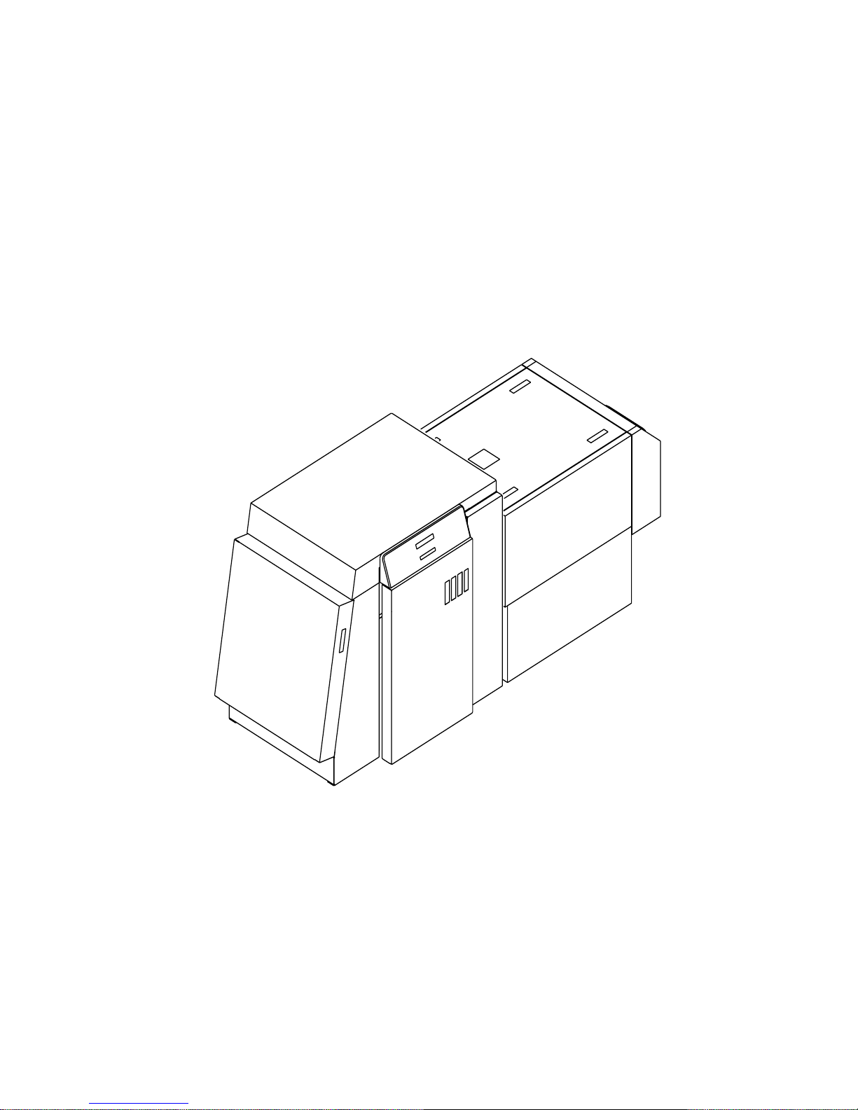
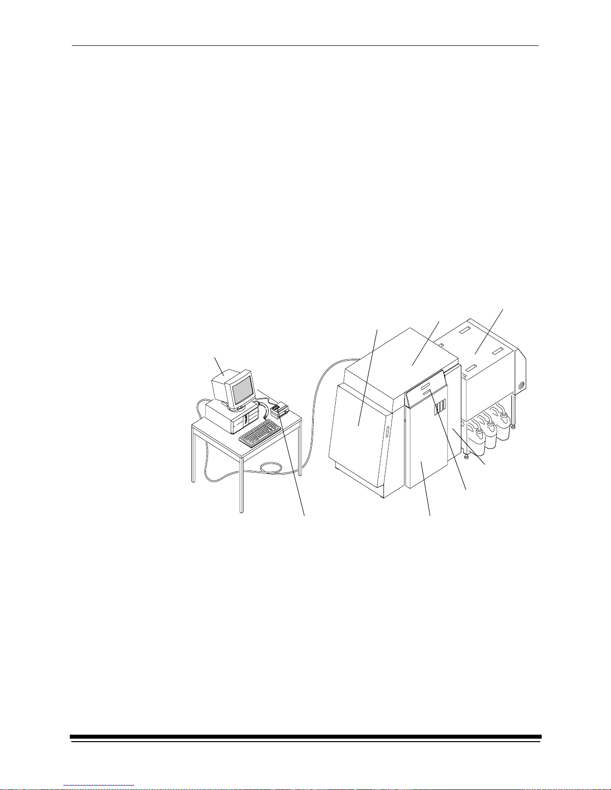
Equipment Overview
Front View
host computer and SCSI cable
(not included)
paper s upply
door
printer
Introduction
processor
sheet
transport
door (front)
densitometer (not included)
October 2002 1-3
front door
operator
control panel
for the printer
Page 20
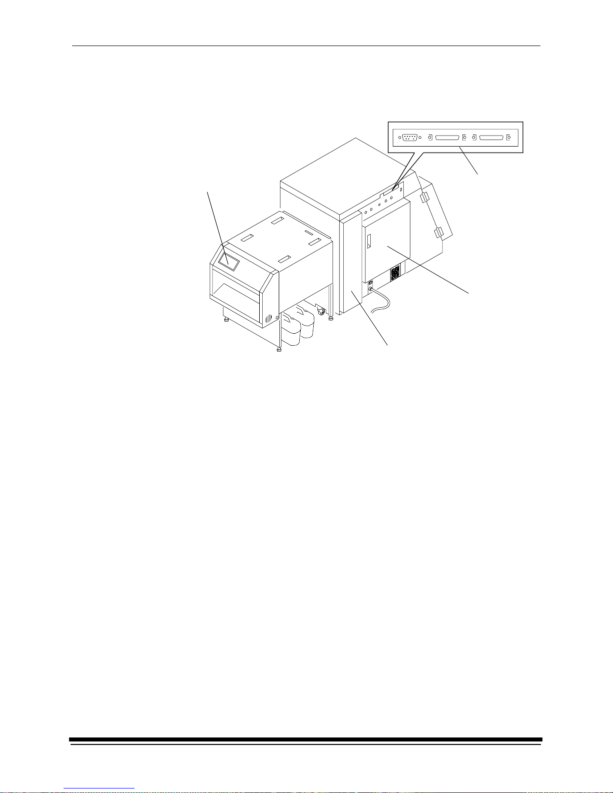
Introduction
Rear View
operator control
panel for the
processor
connector
ports
back door
sheet transport door (rear)
1-4 October 2002
Page 21
This chapter explains how to use the KODAK PROFESSIONAL RP 50 LED
Printer and Processor for daily operations. It takes you from startup to shutdown.
Topics include:
Starting up the Processor ..................................................................................2-1
Starting up the Printer ........................................................................................2-2
Calibrating the Printer ........................................................................................2-3
Obtaining Densities .....................................................................................2-6
Completing the Calibration ..........................................................................2-7
Making Prints .....................................................................................................2-9
Shutting Down the Processor ............... ...... ....................................... ....... ...... .2-10
Shutting Down the Printer .. ...................................... ....... ...... ....... ...... ....... ...... .2-11
Starting up the Processor
1. Check that the circuit breaker switch for the processor is turned on.
2 Using the System
circuit breaker
switch
2. Press On/Off on the processor’s Operator Control Panel to turn the processor
on.
The light above the On/Off key indicates the processor state. A blinking light
indicates that the processor is on but the chemicals are not yet at the correct
working temperature. A continuous light indicates that the processor is ready.
October 2002 2-1
Page 22
Using the System
WARNING:When handling or mixing chemical solutions, wear protective
eyewear, c lothing, and gloves. For safe handing practices with
all chemicals, refer to the MSDS information.
3. Check that the chemistry in each processor tank is at the top of the overflow
pipe. If necessary, add warm water to reach the correct level.
CAUTION: Use water to top off the chemical tanks. Do not use replenisher
chemistry.
overflow
pipe
4. After the temperature is up to the correct level, operate the main drive for
30 minutes. See “Controlling the Processor Drive” on page 3-39.
5. Process a control strip. See “Processing a Control Strip” on page 3-32.
Starting up the Printer
1. Verify that the processor is on, up to the correct temperature, and in control.
2. If needed, turn the circuit breaker on the back of the printer on.
When the Power and Standby LEDs on the OCP are illuminated, press the
Start key on the OCP to begin printer initialization.
If paper is loaded, when initialization is complete (in 3 to 4 minutes) the
message “
complete and the printer is ready to print. Turn the computer on; then go to
the next page and calibrate the printer.
If paper is not loaded, the message “
to load
• “Loading Paper Into the Supply Cassette” on page 3-6.
• “Installing the Supply Cassette” on page 3-10.
When “
the next page and calibrate the printer.
Status: ON LINE - Ready” appears on the OCP. Startup is
” appears on the OCP. Do the procedures below.
On-line and Ready” is displayed, turn the host computer on. Go to
Out of paper, open supply door
2-2 October 2002
Page 23
Calibrating the Printer
You need to calibrate the printer when you start the system up each day. You also
need to calibrate the printer when
• you change paper
• print quality is questionable
• the temperature at the site changes more than 5° F (2.8° C)
• if running more than one shift, at the beginning of each shift
If you are calibrating at any time other than during the daily startup procedure:
Before you begin, make sure the printer is not receiving printing commands from
the host.
NOTE: Most windows displayed in this section are from the Windows NT version
of the software. The windows for the Macintosh version of the software are
similar.
For information about editing the calibration settings (for example, you may want
to display a calibration graph only if calibration is out of tolerance), see “Editing
the Calibration Configuration” on page Appendix C:-19.
Using the System
Calibrate
icon
To calibrate the printer:
1. Check that:
• the densitometer is connected and calibrated
• the printer status is “Online and Ready”
• the processor is in control
• the calibration application is running
2. Select the icon for the LED Printer on the KODAK Device Calibration screen
and click the Calibrate icon. The calibration software needs complete control
of the printer to successfully calibrate the printer.
IMPORT ANT:If no icon appears on the KODAK Device Calibration Screen, you
will need to add a calibration device. See “Adding a Device” on
page C-6.
October 2002 2-3
Page 24
Using the System
Go icon
This icon highlights after
you select Go
The LED Calibration screen appears.
3. Click the Go icon to start the calibration cycle.
Downloading LUTs and Sending Test Print highlights.
If the configuration file specifies to Ask if processor is in control, the
Process In Control dialog box appears.
The processor is critical to printer calibration. You can calibrate the printer
only if the processor is in control. Densitometers require calibration at regular
intervals. Refer to your densitometer’s manual for instructions on how to
calibrate your densitometer.
4. Click Yes.
2-4 October 2002
Page 25
Using the System
The Send LUT to Printer screen appears.
NOTE: The highlighted LUT in the dialog box above is the most recent
calibration LUT.
5. Click either Load Selected LUT or Load Custom LUT (or Cancel to cancel
the calibration process).
If you click Load Selected LUT, the system automaticall y down lo ads the
highlighted LUT to the printer to create a test print.
When the test print has been sent, the Scanning Processed Print with
Densitometer status icon on the LED Printer Calibration screen highlights.
Go to “Obtaining Densities” on page 2-6.
6. If you selected Load Custom LUT in step 5, the Open dialog box appears.
Select or type the name of the LUT file you want and click Open.
October 2002 2-5
Page 26
Using the System
The system automatically downloads the LUT file to the printer to create a test
print. When the test print has been sent to the printer, the Scanning
Processed Print with Densitometer status icon on the KODAK LED Printer
Calibration screen highlights.
Obtaining Densities
Obtaining Densities from a File
If the configuration settings include obtaining the density data from a file, the
Waiting for Density File dialog box appears. Otherwise, go to “Using the
Densitometer to Read Densities.”
NOTE: T o create a density file, see “Creating a Density File for Use with Calibration”
on page Appendix C:-32.
1. Click OK to continue with the calibration process.
2. Go to “Completing the Calibration” on page 2-7.
Using the Densitometer to Read Densities
Do the following to scan the neutral (gray) patches on the processed test print into
the densitometer (refer to your densitometer manual for detailed instructions on
using the densitometer):
1. Slide the lever on the densitometer to position 15. Align the edge of the test
print with the lever on the densitometer. Gently feed the test print through the
densitometer to scan the patches labeled “even”.
2. Slide the lever on the densitometer to position 20. Align the edge of the test
print with the lever on the densitometer. Gently feed the test print through the
densitometer to scan the patches labeled “odd”.
2-6 October 2002
Page 27
Using the System
3. Slide the lever on the densitometer to position 30. Align the edge of the test
print with the lever on the densitometer. Gently feed the test print through the
densitometer to scan the patches labeled “both”.
Lever
Test print
If the test print is read successfully, several messages will appear in the status
bar; the final message indicates that the densitometer values have been
successfully received. Go to “Complet ing the Calibration.”
If the test print is not read successfully, refer to “Calibration Troubleshooting”
on page 5-19.
Completing the Calibration
1. If calibration is in tolerance, the LUT Attributes dialog box appears.
a. Enter a name or comment in the dialog box. The comment you enter will
appear on the Send LUT to Printer screen to identify the LUT file with a
name that is meaningful to you (up to 75 characters).
b. Click OK.
The new printing LUT is calculated and downloaded. “Calibration
Complete” appears in the status bar. The calibration is complete.
2. If calibration is out of tolerance, it may be necessary to run four or more
iterations of the calibration cycle to achieve a successful calibration.
October 2002 2-7
Page 28
Using the System
If the print densities are out of tolerance, a graph appears, allowing you to
select the type of data and planes that you want to see displayed.
a. Click OK.
The following list of options appears.
Re-read the densitometer values is the most useful when the graphs
show an unusual plot. Rereading the test print lets you validate the graph,
then returns you to the Out of Tolerance dialog box.
Iterate again using a newly calculated calibration LUT allows you to
keep printing test prints with the newly created LUT without having to save
the LUT table.
Calculate and download a printing LUT and stop: When you select this
option, the file is saved and given the same creation date and time as the
name.
2-8 October 2002
Cancel and return the printer to its original state saves nothing. Any
corrupted data created after you saved the last time is thrown away.
Page 29

Making Prints
Y ou can make prints with a wide variety of applications that run on WINDOWS NT
Computers and MACINTOSH Computers. One application that is widely used for
printing is the KODAK PROFESSIONAL Imaging System.
Two applications that you may wish to print from are included with the system.
Y ou can use the KODAK PROFESSIONAL Image Print Server for WINDOWS NT
to print TIFF images. You can use the Export Module for ADOBE PHOTOSHOP
that runs on MACINTOSH Computers to print images from the PHOTOSHOP
application.
For more information about these applications, see the appropriate Appendix in
this guide.
Using the System
b. Select one of the four options to try to complete the calibration
successfully.
• If the Out of Tolerance dialog box appears again, repeat this step until
you get a successful calibration; go to step 1.
• If you cannot get a successful calibration, request help from a system
administrator or service person.
October 2002 2-9
Page 30
Using the System
Shutting Down the Processor
To shut down the processor, press the On/Off key on the processor OCP.
Shutting down the processor for service
If you are shutting the processor down for service, turn off the processor circuit
breaker after the green light on the OCP is no longer illuminated. The exhaust fan
in the processor will continue to operate.
IMPORTANT: If the processor will not be used for longer than four days, drain,
flush, and clean the processor tanks.
1. Remove the top cover and the light tight cover from the processor.
top cover
light tight cover
2-10 October 2002
Page 31

Using the System
CAUTION: Install a splash guard over the entrance area of the processor
to prevent water and chemicals from entering the printer.
2. Pour warm water over the top of the rollers.
splash guard
top rollers
3. Reinstall the light tight cover and the top cover on the processor.
NOTE: After the processor is turned off, the recirculation pumps continue to
operate for 30 seconds.
Shutting Down the Printer
1. Check that all jobs in the print queue are printed.
2. Perform a soft shutdown:
a. Press the On/Off Line key on the OCP to take the printer offline.
b. Press the Menu button on the OCP to access the menu.
c. Select “Shutdown” in the message display.
d. Press the Start key.
e. Select “Shutdown now” in the message display.
f. Press the Select key to begin the shutdown.
NOTE: If any jobs are not complete, you will be asked if you want to delete the
remaining jobs before you can select Shutdown.
October 2002 2-11
Page 32

Using the System
CAUTION: Turn off the circuit breaker only after doing the soft shutdown.
Otherwise, you could lose printer status information and
cause dark lines to appear in the middle of the prints if paper
is loaded.
3. Turn off the circuit breaker on the back of the printer.
circuit breaker
2-12 October 2002
Page 33

3 System Operating Procedures
This section provides the information you need to operate the KODAK
PROFESSIONAL RP 50 LED Printer. Topics include:
Operating the Printer .........................................................................................3-2
Operator Control Panel ..................................... ....................................... ...3-2
Printing Deferred or Buffered Jobs...............................................................3-4
Status Messages .........................................................................................3-5
Loading Paper Into the Supply Cassette .....................................................3-7
Reaching the End of the Roll of Paper ......................................................3-13
Removing the Chad ..................................................................................3-14
Handling and Storing the Paper ................................................................3-14
Accessing the Printer Features ........................................................................3-15
Shutdown and Restart ...............................................................................3-15
Unload Supply ...........................................................................................3-15
Selecting SCSI Ports ... ...... ....... ...... ...... ....... ....................................... ...... .3-15
Managing a Modem ..................................................................................3-16
Setting the Printer Time and Date .............................................................3-17
Setting the Paper Length ..........................................................................3-17
Selecting the Slug Width for the Paper .....................................................3-18
Setting the Page Starts Value ...................................................................3-19
Accessing the Software Version Number ..................................................3-22
Setting the Copyright Detection Feature ...................................................3-22
Resetting the Defaults ...............................................................................3-23
Changing the Units of Measurement for Paper Sizes ...............................3-24
About Printing .................... ...................................... ....... ...... ....... ...... ....... ...... .3-24
Image Size ................................................................................................3-24
Buffered and Unbuffered Jobs (or Immediate and Deferred) ....................3-24
Host Software Functions Supported by the Printer ...................................3-25
Operating the Processor ..................................................................................3-26
Operator Control Panel ..................................... ....................................... .3-26
Operational Modes ...... ...... ....... ...... ...... ....... ...... ....... ...... ....... ...... ....... ...... .3-30
Processing a Control Strip ........................................................................3-32
Viewing/Setting the Processor Time and Date ..........................................3-33
Viewing/Setting the Seven-Day Timer ......................................................3-34
Viewing the Software Identification ................... ....... ...... ....... ...... ..............3 -34
Viewing/Setting the Temperatures ............................................................3-35
Calibrating the Temperatures ....................................................................3-35
Resetting the Min Max Temperatures .......................................................3-35
Viewing/Setting Replenishment Settings ..................................................3-36
Calibrating the Replenishment Flow Rate .................................................3-36
Managing the Development Time .............................................................3-37
Managing the Material Sensors ................................................................3-38
Controlling the Processor Drive ................................................................3-39
Computer Reset ................................... ....... ....................................... ...... .3-39
Changing the Wash/Stabilizer Setup ........................................................3-40
Changing the Metric/Fahrenheit Mode ......................................................3-40
Setting the Development Time Tolerance .................................................3-41
Setting the Chemical Temperature Tolerance ..........................................3-41
Clearing Error Conditions ..........................................................................3-41
October 2002 3-1
Page 34

System Operating Procedu re s
Operating the Printer
Operator Control Panel
The operator control panel (OCP) for the printer allows you to view and control:
• current status of t he printer
• current time of day
• paper specifications
• error and power status
• cancel, on/off line and menu functions
• parameters of the printer
• error messages
current status
LCD display
time of day
lights
LED indicator
Status: Initializing
Status: Initializing
Pages Waiting: Paper Width:
Paper Width:
Next Print (sec): Paper Supply:
Paper Length:Paper Length:
2:43
100Paper Width:
0
Power Error Standby
Cancel On/Off Line Menu
Start
Select
Select
key
printing information
Up, Down and Right
function keys
select keys
The display on the OCP is a 4 line by 40 character liquid crystal display (LCD). An
audible beeper is installed to the right of the LCD display. Each of the function
keys also operates as the arrow key (selector) directly below it when Menu has
been pressed. LED indicator lights illuminate to indicate power, error , and standby
statuses.
The operator control panel (OCP) displays the current status of the printer,
including the following infor mat ion :
• Pages Waiting – the number of printing jobs that are waiting in the print queue
• Next Print (sec) – the approximate amount of time (in seconds) until the next
sheet of processed paper will exit the processor
• Paper Width – the width of the current roll of paper that is installed in the
printer
• Paper Supply – the approximate amount of paper left in the paper cassette.
This information is input by you and is for your convenience only
3-2 October 2002
Page 35

OCP Key/Light Descriptions
System Operating Procedures
Key/Light
Start
Cancel
On/Off Line
Menu
Select
Key /LED
Indicator Light
Description/Function
Start Key The Start key turns on the power for the printer when the printer has
been shut down through the OCP. When using the OCP menu, the
Start key functions as a Select key to select the highlighted item
from the OCP menu.
Cancel Key Pressing Cancel causes the job that is currently printing to quit. In
addition, the printer automatically goes into the Offline mode after
the current printing job has quit.
On/Off Line Key This key toggles between the Online and Offline modes. If you press
this key when the printer is in the Online mode, the printer goes into
the Offline mode. If you press this key when the printer is in the
Offline mode, the printer goes into the Online mode.
Menu Key Pressing this ke y ac ti vat e s the menu f or th e OCP when the printer
is in the Offline mode.
Arrow Keys When using the OCP menu, the Cancel key functions as a Right
Arrow, the On/Off Line key functions as an Up Arrow and the
Menu key functions as a Down Arrow.
Select Key When using the OCP menu, the Start key functions as a Select key
to select the highlighted item from the OCP menu.
Power
Error
Standby
Power Light The power light illuminates to indicate that the main power for the
printer is on.
Error Light The error light illuminates to indicate that a printer error occurred.
Standby Light The standby light illuminates to indicate that the printer has been
shut down from the OCP and is now in the Standby mode, waiting
for Start to be pressed.
October 2002 3-3
Page 36

System Operating Procedu re s
Menu
The menu allows you to access other printer features.
NOTE: To access the menu, the print queue must not have any pages waiting to
1. Press On/Off Line to take the printer offline.
2. Press Menu.
Printer Offline Feature
This feature is useful when you need to access the printer OCP menu.
When the printer is offline, it cannot send jobs to the processor or accept jobs
from the host.
To take the printer offline, press On/Off Line on the OCP. If a job is printing when
you take the printer offline, the job will complete printing. When you put the printer
back online, the sheet will be sent to the processor.
Online Mode
The Online mode is the normal mode and must be activated for the printer to
accept print jobs from the host computer.
be printed.
Offline Mode
When the printer is in the Offline mode it cannot accept print jobs from the host
computer and will not send any sheets to the processor. When an error occurs,
the printer is automatically placed into the Offline mode.
Cancelling Jobs
To cancel the sheet currently being printed, press Cancel on the OCP. After the
sheet has been cancelled, the printer automatically toggles to the Offline mode.
To cancel all jobs waiting to be printed:
1. Press Cancel on the OCP to cancel the sheet that is currently printing.
2. Press Menu twice.
Printing Deferred or Buffered Jobs
“Pages Deferred” displays on the OCP and a number other than zero displays in
the Pages Waiting field when one or more jobs are waiting to be printed.
1. Press On/Off Line to take the printer offline.
2. Press Menu.
3. Press Start to print the jobs.
3-4 October 2002
Page 37

System Operating Procedures
Status Messages
Status messages display on the LCD display of the OCP to indicate the status or
current state of the printer.
Status Message/Printer State Definition
status: ON LINE – Ready The printer is idle and ready to accept jobs.
status: ON LINE – Processing The printer is currently downloading a job,
processing a job.
status: ON LINE – Pages Deferred Pages are waiting and nothing is being
downloaded. If jobs were sent with the “Defer
Print” or “Buffer” option, the printer is waiting
for more data to fill the frame store.
status: ON LINE – Printing The printer is currently printing and may also
be processing more jobs.
status: OFF LINE – Idle The printer is currently offline. No jobs exist in
the printer. “Idle” is used instead of “Ready”
because the printer is actually idle (not doing
anything) and will not accept jobs.
status: OFF LINE – Processing The printer is offline but a job is being
downloaded. A print cycle will not be initiated.
status: OFF LINE – Pages Deferred The printer is offline but there are jobs in the
printer that are waiting to be printed. A print
cycle will not be initiated.
status: OFF LINE – Printing The printer will complete the current print cycle
and then pause.
status: OFF LINE – Cancelling Cancel was pressed when the printer was
printing. The sheet that was printing was
immediately terminated. This message is also
displayed when you select “Yes” to the prompt
to cancel all remaining jobs when you enter
the menu.
status: Initializing The printer is powering up (after Standby has
been pressed or the printer has been turned
on).
status: ON LINE – Resetting The print engine is being reset because of an
error or operator intervention. The printer
returns to the “ON LINE – Ready” state after
the machine reset is complete (even if the
printer was offline because of an error or key
that was pressed before the reset).
status: Printer Error:
<Error Message>
October 2002 3-5
A printer error (such as a p aper jam) occu rred.
The error message is displayed on the second
line of the display. For a complete list of error
messages, see “Printer Error Messages” on
page 5-2.
Page 38

System Operating Procedu re s
Loading Paper Into the Supply Cassette
WARNING: Move the supply cassette from the printer to a table to load or
One 10 to 20 inch supply cassette is included with the printer and is designed to
hold rolls of paper that are 25.4 cm, 27.9 cm, 30.4 cm, 50.8 cm and A4 widths.
Removing the Supply Cassette
1. Open the paper supply door.
2. Unlock the cassette clamp for the supply cassette.
3. Remove the empty supply cassette.
unload paper.
supply cassette
cassette
clamp
paper supply door
3-6 October 2002
Page 39

System Operating Procedures
Loading Paper into the Supply Cassette
1. Unlock the supply cassette.
2. Open the supply cassette.
3. If necessary, remove paper scraps from the core support assembly.
4. Remove the old core and support assembly from the supply cassette.
NOTE: Keep the felt surfaces clean to prevent scratches on the paper.
old core and core support assembly
felt
5. Remove the screw lock and the old cardboard core from the core support
assembly.
6. Move the screw adjuster to the correct position for the paper size you are
loading. Pull the metal spring for the screw adjuster away from the gear and
slide the screw adjuster to the correct position until it locks into place in the
detent.
supply cassette locks
screw adjuster
felt
gear
October 2002 3-7
core support
assembly
cardboard core
screw lock
Page 40

System Operating Procedu re s
7. Position the paper so that the lead edge of the paper is away from you.
8. Insert the core support assembly into the roll of paper as shown.
9. Push the cardboard core toward the gear until it engages the detent.
TIP: Practice the following steps in the light with an empty cardboard core
before you load a new roll of paper in the dark.
CAUTION: Loading paper into the paper cassette must be completed in
a darkroom with the lights off.
cardboard core
detent
10. Install the screw lock onto the core support assembly and ensure that it is
snug.
CAUTION: Do not overtighten the screw lock.
11. Place the core support assembly with the full paper roll into the supply
cassette.
3-8 October 2002
Page 41

System Operating Procedures
IMPORT ANT :Make sure that the right and left edges of the paper on the paper
roll remain aligned. Do not allow the roll of paper to slide or
“telescope.”
screw lock
12. Feed the lead edge of the paper through the slotted opening in the paper
cassette.
lead edge of the paper
slotted opening
image or emulsion
side
core support assembly
(side without the gear)
13. Close the supply cassette and latch the supply cassette locks.
NOTE: Be sure that the core support assembly rotates freely in the supply
cassette and that the paper feeds freely.
October 2002 3-9
Page 42

System Operating Procedu re s
supply cassette lock
When the paper cassette is locked, you can turn on the room lights.
IMPORT ANT:When moving the supply cassette, pick up and carry the cassette
by both handles to prevent the paper from sliding or “telescoping”
to one side.
Installing the Supply Cassette
1. Open the sheet transport door and remove any chad. See "Removing the
Chad" on page 3-14.
2. Check the knife and, if necessary, remove the trail edge of the paper from the
previous roll through the chad area.
paper supply door
sheet transport
door
knife
chad area
chad
3. Close the sheet transport door.
4. Open the paper supply door.
3-10 October 2002
Page 43

System Operating Procedures
5. Align the slot on the bottom of the supply cassette with the plate on the bottom
of the shelf and slide the full supply cassette into place on the shelf.
Emulsion
(image) side of
paper
shelf
plate
cassette clamp
slot
6. Check that the gear on the supply cassette aligns and meshes with the gear
on the printer.
7. Lock the clamp to secure the supply cassette into place.
8. Ensure that the cut on the lead edge of the paper is straight.
CAUTION: Use scissors to cut the paper. Knives and razor blades will
shred the paper.
9. Press Start on the OCP.
10. When prompted, enter the number of feet on the roll of paper.
11. When the message “Feed paper into printer...” appears, pull the lead edge of
the paper out of the supply cassette and place it under the idler roller.
12. Feed the lead edge of the paper into the printer until you feel it being pulled.
Keep the left edge of the paper against the paper alignment guide.
IMPORT ANT:Guide the paper into the printer while pressing down each edge
to prevent slack in the paper.
October 2002 3-11
Page 44

System Operating Procedu re s
gear on the
cassette
CAUTION: If the paper does not load properly or a paper jam occurs,
press Cancel. Remove any paper from the shoe area and
repeat steps 6 through 12. Make sure the lead edge is cut
square.
paper alignment
guide
lead edge of
the paper
idler
roller
gear on the
printer
13. Close the paper supply door. The paper automatically feeds into position for
printing and the fogged section at the lead edge of the roll is trimmed off. The
message “Status: ON LINE – Ready” appears when initialization is complete.
cassette
clamp
3-12 October 2002
Page 45

System Operating Procedures
Reaching the End of the Roll of Paper
When the end of the roll of paper is reached, the OCP displays one of two
messages:
• “Out of paper, open supply door to load...” — indicates that the supply
cassette is empty. To remove the paper, open the supply door and pull the
paper out of the shoe.
• “End of roll, remove sheet from sheet transport” — indicates that the
supply cassette is empty. In this situation, the paper cannot be reversed into
the roll supply area since the trail edge of the paper has moved into the shoe.
The remaining paper is then moved forward into the sheet transport area with
the lead edge of the paper just beyond the knife. To remove the paper, grasp
its lead edge and pull it out of the shoe.
NOTE: If necessary , gently push the deflector down and use the shoe exit roller
knob to advance the paper into the chad area.
paper
shoe exit roller knob
deflector
October 2002 3-13
Page 46

System Operating Procedu re s
Removing the Chad
Chad is wasted paper that is cut from the lead edge of the paper roll by the knife.
It is deposited in the chad area of the printer.
sheet transport
door
chad area
chad
This waste is usually necessary to remove fogged paper (paper that has been
exposed to light). The waste may also be necessary to ensure a straight lead
edge on the roll of paper and accurate positioning of the lead edge in the shoe.
Chad is cut from the roll when:
• new paper is installed in the printer
• the printer is reinitialized after one of the printer doors has been opened
• the printer is reinitialized to ensure a square lead edge on the paper roll
IMPORT ANT: Open the sheet transport door and remove the chad from the chad
area every time you load a new roll of paper into the printer.
Handling and Storing the Paper
Follow the instructions included with the paper for storing and handling the paper
properly.
IMPORTANT: Avoid storing paper in low humidity conditions.
Storing Paper Using the Soft Shutdown Feature
The Soft Shutdown feature (see “Shutting Down the Printer” on page 2-11) causes
the rollers to automatically reverse to rewind the lead edge of the paper to the first
metering roller during the soft shutdown process.
3-14 October 2002
Page 47

Accessing the Printer Features
Shutdown and Restart
Shutdown
1. Select “Shutdown” from the main menu on the OCP.
2. Select “Shutdown NOW?”
This causes the printer to shut down operations and enter the standby mode.
Restart
1. Select “Restart” from the main menu on the OCP.
2. Select “Restart NOW?”
This causes the printer to immediately shutdown operations and reboot.
IMPORTANT:This shutdown is not a soft shutdown and does not save the
parameter settings that have been made since the previous
startup. Also, using this feature may cause a black line on the
paper in the shoe.
System Operating Procedures
Unload Supply
1. Select “Unload Supply” from the main menu.
2. Select “Unload Supply NOW?”
The printer enters its unload paper sequence. When the unload paper
sequence is complete, the OCP returns to the main menu.
3. Select “Exit” to return to the OCP display. You are prompted to load another
roll of paper into the printer.
Selecting SCSI Po r ts
1. Select “Setup” from the main menu on the OCP.
2. Select “Ports”.
3. Select “SCSI”.
4. Select “SCSI Target ID”.
5. Use the Up and Down Arrows to select a new SCSI ID. The allowable SCSI
IDs are 0, 1, 2, 3, 4, 5, 6, 7.
6. Press Select to select/set the new value.
7. Select “Exit” to return to the previous menu on the OCP.
October 2002 3-15
Page 48

System Operating Procedu re s
Selecting the Target Pad Read Options
1. Select “Setup” from the main menu on the OCP.
2. Select “Ports”.
3. Select “SCSI”.
4. Select “Target Pad Reads”.
5. Use the Up and Down Arrows to select “Yes” or “No” to indicate whether or
6. Press Select to select/set the new value.
7. Select “Exit” to return to the previous menu on the OCP.
Managing a Modem
Resetting the Modem Port
1. Select “Setup” from the main menu on the OCP.
not the SCSI device driver will pad initiator read requests with zeros to the
requested length or terminate the SCSI read transaction when it has sent only
the data it has to send.
2. Select “Ports”.
3. Select “Modem (Diag)”.
4. Select “Reset Port”.
5. Select “Reset Modem Port Now”.
NOTE: This causes the modem port to be set to its original factory setting.
6. Select “Exit” to return to the previous menu on the OCP.
Checking for a Modem
NOTE: This causes the printer to query the modem port for the presence of a
modem.
1. Select “Setup” from the main menu on the OCP.
2. Select “Ports”.
3. Select “Modem (Diag)”.
4. Select “Check Presence”.
5. Select “Check Modem Presence Now”.
6. Select “Exit” to return to the previous menu on the OCP.
3-16 October 2002
Page 49

System Operating Procedures
Setting the Printer Time and Date
Setting the Current Time
1. Select “Setup” from the main menu on the OCP.
2. Select “Time”.
3. Select “Current Time”.
4. Use the Up and Down Arrows to select a new time.
5. Press Select to save the new value.
6. Select “Exit” to return to the previous menu on the OCP.
Setting the Current Date
1. Select “Setup” from the main menu on the OCP.
2. Select “Time”.
3. Select “Current Date”.
4. Use the Up and Down Arrows to select a new date.
5. Press Select to save the new value.
6. Select “Exit” to return to the previous menu on the OCP.
Setting the Current Day
1. Select “Setup” from the main menu on the OCP.
2. Select “Time”.
3. Select “Day”.
4. Use the Up and Down Arrows to select a new day.
5. Press Select to save the new value.
6. Select “Exit” to return to the previous menu on the OCP.
Setting the Paper Length
The value displayed is the length of paper (in feet) that remains on the supply roll.
This number should be edited when a new or partially used paper roll is installed
in the printer. You receive a prompt to enter this number when a new roll is being
loaded into the printer. The range for paper is 0 to 999.
1. Select “Setup” from the main menu on the OCP.
2. Select “Paper”.
3. Select “Current Length”.
4. Use the Up and Down Arrows to select a new length for the paper.
5. Press Select to select/set the new value.
6. Select “Exit” to return to the previous menu on the OCP.
October 2002 3-17
Page 50

System Operating Procedu re s
Selecting the Slug Width for the Paper
You can determine the width of the lead and trail edge borders on the prints by
selecting the slug width. The slug width is the total width of the lead and trail edge
borders (white space) of the paper that remains between the sheets of paper.
1. Select “Setup” from the main menu on the OCP.
2. Select “Printer”.
3. Select “Slug Width”.
4. Use the Up and Down Arrows to select a new slug width.
5. Press Select to select/set the new value.
6. Select “Exit” to return to the previous menu on the OCP.
Example: image size=20 inches, slug width=0.25 inches (total for lead/trail edge)
The slug width range is 0 to 250 pixels (0 to 1 inch).
IMPORTANT :The lead and trail edge cannot be borderless. The slug width
should be at least 32 pixels (0.125 inches).
0.125 inches 0.125 inches
Example: image size=four 8 inch images printed during one print cycle
___________
_ _ _ _ _ _ _ _ _ _
represents the image boundary
represents the cut edge
3-18 October 2002
Page 51

System Operating Procedures
Setting the Page Starts Value
The value for “page starts” indicates the number of pixels between the back wall
of the printer and the edge of the image. For example, when the printer begins to
print, it moves the print head to the back wall of the printer and then advances it
toward the front of the printer by the number of pixels specified in the “page starts”
parameter (value).
The “page starts” value is set so that the image edge closest to the back of the
printer will print off the paper and will then be borderless on the back edge of the
print.
NOTE: If the image size is wider than the paper, the front edge of the image will
also be borderless.
1. Select “Setup” from the main menu on the OCP.
2. Select “Printer”.
3. Select “Page Starts”.
4. Select the page start you wish to modify.
5. Use the Up and Down Arrows to select a new page start value.
6. Press Select to select the new value.
7. Select “Exit” to return to the previous menu on the OCP.
October 2002 3-19
Page 52

System Operating Procedu re s
Producing Borderless Prints
To achieve borderless prints on both the front and back edges of the paper, you
must set the Page Starts value to adjust the location of the image so that both
edges of the image print off the paper.
NOTE: The image width should be at least 76 pixels wider than the width of the
paper to ensure a borderless print.
Paper Size Image Width in Pixels
10 inch 2576
11 inch 2826
12 inch 3076
20 inch 5076
A4 3000
outline of the paper
outline of the image
page start
back edge
front edge
If white borders are present on either the front or back edge of the print:
1. Measure the white border at both the lead (distance A) and the trail edge
(distance B) and determine its average width.
2. Convert the average width of the white border to a pixel value. To do this,
multiply the width by 250 and add 76.
3-20 October 2002
Page 53

System Operating Procedures
3. Adjust the page starts value to the calculated pixel value. If the white border is
on the:
• back edge: reduce the page start value by the pixel value
• front edge: increase the page start value by the pixel value
distance A
cut edge
distance B
cut edge
IMPORTANT:The page start value for each paper width is different.
October 2002 3-21
Page 54

System Operating Procedu re s
Accessing the Software Version Number
To view the software version of the FEE, PEC and OPC circuit boards:
1. Select “Setup” from the main menu on the OCP.
2. Select “Printer.”
3. Select “More.”
4. Select “Version” to view the version number for the FEE, PEC and OPC
5. Select “Exit” to return to the previous menu on the OCP.
Setting the Copyright Detection Feature
The Copyright Detection feature is designed to protect the copyrighted images of
professional photographers. This feature is applied to prevent images from being
duplicated.
1. Select “Setup” from the main menu on the OCP.
2. Select “Printer.”
circuit boards.
3. Select “Copyright Detection.”
4. Use the Up and Down Arrows to select “Always On”, “Always Off” or “Host
Select.”
5. Press Select to select/set the setting for the new option.
6. Select “Exit” to return to the previous menu on the OCP.
Host Select Always On Always Off
Copyright Detection
can be enabled or
disabled by the host on
a print by print basis
for each image that is
downloaded to the
printer.
Copyright Detection is
enabled for every
image that is
downloaded to the
printer.
Copyright Detection is
disabled for every
image that is
downloaded to the
printer.
3-22 October 2002
Page 55

System Operating Procedures
Resetting the Defaults
Resetting the Parameters
This procedure resets the parameters of the printer to the factory setup (default)
values. T o indicate that the values have been reset to the factory setup values, the
word “done” is displayed in parenthesis after “Reset Parameters To Factory” on
the menu.
NOTE: Diagnostic parameters are not reset by this action.
1. Select “Setup” from the main menu on the OCP.
2. Select “Defaults”.
3. Select “Reset Parameters to Factory”.
4. Select “Exit” to return to the previous menu on the OCP.
Resetting the Printing LUTs
This procedure resets the Printing LUTs stored in nvram to the factory setup
(default) values. To indicate that the values have been reset to the factory setup
values, the word “done” is displayed in parenthesis after “Reset Printing LUTs To
Factory” on the menu.
1. Select “Setup” from the main menu on the OCP.
2. Select “Defaults”.
3. Select “Reset Printing LUTs to Factory”.
4. Select “Exit” to return to the previous menu on the OCP.
Resetting the Copyright Detection LUTs
This procedure resets the Copyright Detection LUT s stored in nvram to the factory
setup (default) values. To indicate that the values have been reset to the factory
setup values, the word “done” is displayed in parenthesis after “Reset Copyright
LUTs To Factory” on the menu.
1. Select “Setup” from the main menu on the OCP.
2. Select “Defaults”.
3. Select “Reset Copyright LUTs to Factory”.
4. Select “Exit” to return to the previous menu on the OCP.
October 2002 3-23
Page 56

System Operating Procedu re s
Changing the Units of Measurement for Paper Sizes
1. Select “Setup” from the main menu on the OCP.
2. Select “Printer”.
3. Select “More”.
4. Select “Units”.
5. Select “Units” again.
6. Use the Up and Down Arrows to select either “English” or “Metric”.
7. Press Select to select/set the new value.
About Printing
• A print job is not printed until it is completely downloaded to the printer.
• Print jobs are printed in the order they are received.
• If multiple copies of a print job are requested, they are positioned next to each
• It takes the same amount of time to print (expose the paper) a length of 6.5
IMPORTANT:Select “Exit” to return to the previous menu on the OCP.
other down the length of the roll, regardless of the width of the image.
inches as it does to print 33 inches.
Image Size
The minimum image length is 6.5 inches (1625 pixels). White space is
automatically added to images smaller than 6.5 inches to increase the image size
to this minimum.
The minimum sheet length is 8 inches. A sheet that is cut for an image less than
this size will have white space added to it to increase it to this minimum length.
The maximum image length is approximately 33 inches (8248 pixels).
Buffered and Unbuffered Jobs (or Immediate and
Deferred)
Jobs can be stored in memory when downloaded from the host until enough jobs
are downloaded to maximize the printing that occurs during the print cycle.
Most host applications have an option to indicate whether to print the job as soon
as it completes downloading to the printer or to wait until the printer has a full
buffer to print.
If the print job is sent to the printer with the Unbuffered/Immediate option, the job
will be printed as soon as it completes downloading to the printer. Regardless of
the number of (or size of) the jobs in the printer waiting to print, jobs sent with this
option are printed separately.
3-24 October 2002
Page 57

System Operating Procedures
If the print job is sent to the printer with the Buffered/Deferred option, this indicates
to the printer to wait until it has a full buffer before printing. A full buffer is 26.5 to
33 inches. A print job sent with this option is printed when:
• the buffer is full
• the next print job received will not fit within the full buffer length
• the next print job received is requested to be printed unbuffered/immediate
(the job received this way is printed by itself)
• the buffer is forced to be printed (see “Printing Deferred or Buffered Jobs” on
the next page)
• the buffer is full and the next print job has started downloading to the printer
NOTE: If your host application needs to wait until a print job has been completely
downloaded to the printer before it can begin processing the next print job,
this option should not be used with larger width paper. It will slow down the
productivity of your system.
Printing Deferred or Buffered Jobs
“Pages Deferred” displays on the OCP and a number other than zero displays in
the Pages Waiting field when one or more jobs are waiting to be printed.
1. Press On/Off Line to take the printer offline.
2. Press Menu.
3. Press Start to print the jobs.
Host Software Functions Supported by the Printer
The printer supports bar coding and pixel doubling, which may be available
through your host software. Check the documentation for your host software to
see if these functions are available and how to use them.
Bar Coding
The bar coding function can be used for order tracking, package cutting (for
example: Type 208), etc.
Pixel Doubling
The pixel doubling function can be used to double the size of an image.
October 2002 3-25
Page 58

System Operating Procedu re s
Operating the Processor
Operator Control Panel
The operator control panel (OCP) for the processor allows you to view and
control:
• chemical and dryer temperatures
• development time
• chemical replenishm ent rate
• current day and time
• automatic startup and shutdown times
• equipment status checks
• error messages
LCD display
Set key
current mode
current
feature
information
SET
LED indicator
lights
blue function keys
The keypad on the OCP is covered with a plastic overlay and can be easily wiped
clean using a damp cloth. The display is a two-line liquid crystal display (LCD).
The top line indicates whether the processor is in the View, Set, Calibrate or Min
Max mode. The bottom line indicates the current feature information, menu
selections, etc. and is called the working line.
- - - SET - - -
MON OFF 15:00
Reset keys
Up and
Down
Arrows
View Mode
The View mode is the normal screen mode. In this mode current processing
conditions, device settings and messages from the processor can be viewed.
Set Mode
The Set mode is used to change the operation settings of the processor.
Calibrate Mode
The Calibrate mode is used to calibrate devices and ensure that the processor is
accurately tracking and displaying equipment conditions.
Min Max Mode
The Min Max mode is used to view the minimum and maximum readings for the
device that is current.
3-26 October 2002
Page 59

OCP Key/Light Descriptions
System Operating Procedures
Key/Light
SET
Key /LED
Indicator Light
Description/Function
Set Key Pressing Set causes the screen to change from View mode to either
Set mode, Calibrate mode, or Min Max mode. In Set mode, a device
can be set to “ON”, “OFF” or “AUTO” or a new operating parameter
can be entered. In Calibrate mode, an adjustment offset for the
device can be entered. In Min Max mode, the maximum and
minimum readings for the device can be viewed or reset.
Up Arrow The Up Arrow has two functions depending on the keyboard mode.
In View mode, this key is used to scroll the viewing screen that
displays additional devices or information. In Set or Calibrate
modes, this key increases the displayed value.
Down Arrow The Down Arrow has three functions depending on the keyboard
mode. In View mode, this key is used to scroll the viewing screen to
display additional devices or information. In Set or Calibrate modes,
this key decreases the displayed value. In Min Max mode, this key
resets the values to the current measured temperature.
On/Off Key and
On/Off Light
Pressing On/Off turns the processor on and off. The light above
On/Off illuminates continuously when the processor is ready. If the
chemistries are not all at their set temperature when the processor
is on, the light blinks on and off. When the processor is off, the light
is not illuminated.
Time Key and
Time Light
Temperature
Key and
Temperature
Light
Replenishment
Key and
Replenishment
Light
Pressing Time accesses the Time screen. The light above the key
illuminates when the Time screen is active.
Pressing Temperature accesses the Temperature control screen.
The light above the key illuminates when the screen is active.
Pressing Replenishment accesses the Chemical Replenishment
and Wash Control screen. The light above the key illuminates when
the screen is active.
October 2002 3-27
Page 60

System Operating Procedu re s
Key/Light
Key /LED
Indicator Light
Drive Key and
Drive Light
Material Key and
Material Light
Description/Function
Pressing Drive accesses the drive motor control system. The light
above the key illuminates when the Drive key is active.
The Material key is used to access the Material Transport screen.
The Material key can also be used to view the processor setup
parameters, select the control strip screen, and start the control strip
procedure (see “Processing a Control Strip” on page 3-32). The light
above the Material key illuminates when the Material Transport
screen is active. If paper is present at the feed table, the LCD
display on the OCP indicates the size of the paper currently at the
entrance of the processor or at the exit. For example:
NOTE: Moving dots illuminate under the size indicators to indicate
that paper is movin g through the processor.
Reset Keys The Reset keys are the two embossed unmarked keys below the
Power and Material keys. Pressing both Reset keys simultaneously
puts the processor in Reset mode.
Status Messages
Status messages display on the LCD display of the operator control panel to
indicate the status or current state of the processor.
3-28 October 2002
Page 61

System Operating Procedures
OCP On/Off Light
The on/off light switch for the OCP illuminates or deilluminates the entire OCP.
on/off light switch
October 2002 3-29
Page 62

System Operating Procedu re s
Operational Modes
There are three operational modes for the processor:
• Operator
• Key Operator
• Service
To access the features of the processor, it must be in the correct operational
mode. The table below will help you determine the correct operational mode for
each feature.
Feature
Dryer Temperature Yes Yes Yes
Material Mode (A or B) Yes Yes Yes
Clear Jam or Stopped Yes Yes Yes
Control Strip Yes Yes Yes
Current Time/Day Clock Yes Yes Yes
Development Time Yes Yes
Chemical Temperatures Yes Yes
Replenishment Rates Yes Yes
Seven Day Timer On/Off Times Yes Yes
Manual Override of Devices Yes
Calibration Settings Yes
Calibration Cycles Yes
Display of Minimum and Maximum Readings Yes
Memory Dump Yes
Setup Menu Yes
Operator
Mode
Key
Operator
Mode
Service
Mode
3-30 October 2002
Page 63

System Operating Procedures
Adjusting the Key Switch Loc k
The key switch lock is behind the front panel on the side of the OCP.
The following key switch positions determine the operational mode and the
available feature:
key switch lock
• Locked—Operato r mode
• Unlocked—Key Operator mode
• Service—Service Technician mode
Key and Key Switch lock Key Positions
(side view)
key switch
lock
key
Operator Mode
(locked)
(key rotates left and right)
October 2002 3-31
Key Operator Mode
(unlocked)
Service Mode
Position
Page 64

System Operating Procedu re s
Processing a Control Strip
CAUTION: Loading the control strip feed box must be done in a darkroom in
IMPORT ANT: In the next step, make sure the emulsion side of the control strip is
1. With the label on the control strip feed box facing up, feed one control strip
2. Turn the knob on the control strip feed box counterclockwise until the strip is
3. Loosen the spring-loaded knob on the processor and pull it toward the
4. Insert the control strip feed box into the bypass slot and release the spring
5. Tighten the knob to lock the control strip feed box into place. Make sure the
complete darkness.
facing up.
into the box.
completely inside of the box.
NOTES: – If the control strip is fed too far into the box, it jams in the box.
– The control strip feed box holds only one control strip at a time
– The lead edge of the control strip will be fogged.
processor’s OCP.
loaded knob.
box is flush with the processor top cover.
control
strip feed
box
bypass
slot
6. Press Material to select the Material screen.
7. Press Down to select the control strip option.
8. Press Set to acces s the Control Strip screen in Set mode.
NOTE: If the processor is not at the proper temperature, a control strip cannot
be run. The message “TEMP WAIT STRIP” appears until the chemistry
reaches the proper temperature.
spring
loaded
knob
9. Press Material to start the control strip procedure and cancel the Set mode.
3-32 October 2002
Page 65

System Operating Procedures
10. Turn the knob on the control strip feed box clockwise with a steady slow
motion until the processor pulls the control strip or the knob moves freely.
1 1. After the control strip has been processed, loosen the spring loaded knob and
pull it toward the processor’s OCP.
12. Remove the control strip feed box from the bypass slot and release the knob.
13. Push the spring loaded knob toward the printer until the slot is completely
covered and tighten the knob.
NOTE: The processor will operate for two complete dry-to-dry cycles to allow
adequate time for the control strip to load. Replenishment is calculated
for 42 square inches of material.
Viewing/Setting the Processor T ime and Date
Viewing the Current Time Setting
1. Press Time on the OCP to access the Time screen.
NOTE: All times have been entered using a 24-hour clock notation. For
example, 3:12 a.m. is entered and displayed as “3:12”; 3:12 p.m. is
entered and displayed as “15:12”.
2. Press a different blue function key to return to View mode.
Setting the Current Time
1. Press Time.
2. Press Set to enter the Time Set mode. Change the time of day by using the
Up and Down Arrows.
NOTE: The timing selections increase or decrease in increments of one minute
each for the first 10 minutes in either direction. Thereafter the timing
selections increase (or decrease) in 10 minute increments.
3. Press Set twice or press a different blue function key to return to View mode.
Setting the Current Date
1. Press the blue Time key on the OCP.
2. Press Set twice to enter the Day Set mode. Change the day by using the Up
and Down Arrows.
3. Press Set once or press a different blue function key to return to View mode.
October 2002 3-33
Page 66

System Operating Procedu re s
Viewing/Setting the Seven-Day Timer
The seven-day timer allows the processor to turn itself on and off automatically
throughout the week. If the processor is off and the day and time are the same as
an activate time setting, the processor automatically turns on. If the processor is
on and the current day and time match an off time setting, the processor turns off.
If a time is replaced with “not set”, that on/off time is ignored for that day.
The processor does not automatically turn on if the exit end circuit breaker has
been used to turn the processor off.
Viewing the On/Off Times
1. Press Time on the OCP to access the Time screen.
2. Use the Up Arrow to select the seven-day timer.
3. Use either the Up or Down Arrow to select the desired day and its on or off
Setting the On/Off Times
1. Press Time on the OCP.
2. Press Set to put the Time screen in Set mode. Use the Up and Down Arrows
time.
to change the on or off time. Press On/Off to toggle between an active or “not
set” mode.
3. Press a different blue function key to return to View mode.
Viewing the Software Identification
1. Press Time on the OCP to access the Time screen.
2. Press the Down Arrow to select the software identification screen.
3. Press Set once or press a different blue function key to return to View mode.
3-34 October 2002
Page 67

System Operating Procedures
Viewing/Setting the Temperatures
Viewing the Temperature Settings
1. Press Temperature on the OCP to access the Temperature screen.
2. Press the Up or Down Arrow to select the desired heater.
Setting the Temperature
1. View the temperature settings and select the desired heater.
2. Press Set.
3. Use the Up or Down Arrow to change the operating temperature.
4. Press Set to enter the Calibrate mode.
5. Press Set three times or press a different blue function key to return to View
mode.
NOTE: Press Temperature to toggle the heater between Manual Off and
Automatic mode.
Calibrating the Temperatures
IMPORTANT : Before calibrating a temperature sensor, make sure the
temperature has stabilized. The temperature near the probe is not
necessarily the same as the average temperature of the tank or
dryer.
1. View the temperature settings and select the heater.
2. Press Set twice to put the Temperature screen in Calibrate mode.
3. Use the Up or Down Arrows to enter an offset. Changing the offset causes
the displayed temperature to change. Adjust the offset until the displayed
temperature matche s the actual temperature, as measured in the tank.
NOTE: Record and save the calibration value so it can be re-entered if the
memory is cleared.
4. Press Set twice or press a different blue function key to return to View mode.
Resetting the Min Max Temperatures
1. View the temperature settings and select the desired heater.
2. Press Set three times to enter the Min Max mode.
3. Press the Down Arrow to reset the values for the minimum and maximum
temperatures.
4. Press Set once or press a different blue function key to return to the View
mode.
October 2002 3-35
Page 68

System Operating Procedu re s
Viewing/Setting Replenishment Settings
Viewing the Replenishment Rate
1. Press Replenishment to access the Replenishment screen.
2. Press the Up or Down Arrow to select the desired replenishment pump or the
Setting the Chemical Replenishment Rate
1. Select the desired replenishment pump.
2. Press Set to access the Set mode.
3. Use the Up or Down Arrow to change the replenishment needed for each
4. Press Set twice or press a different blue function key to return to View mode.
Setting the Wash Replenishment Rate
wash/stabilizer tank s.
square foot of paper processed.
NOTE: Press Replenishment to toggle the pump to Manual on, Manual off or
Per-Square-Foot mode.
1. Select the desired wash/stabilizer tank.
2. Press Set to access the Set mode.
3. If the wash is in per-square-foot mode, use the Up or Down Arrow to change
the amount of wash solution needed for each square foot of paper processed.
NOTE: In Automatic mode, the wash solution is on whenever material is in the
processor.
4. Press a different blue function key to return to View mode.
NOTE: Press Replenishment to toggle the pump to Manual on, Manual off,
Per-Square-Foot, or Automatic mode.
Calibrating the Replenishment Flow Rate
NOTE: Turn the key switch to the service position before you calibrate the
replenishment flow rate.
IMPORTANT: Before calibrating a flow rate, position the desired replenishment
tube into a beaker to catch the pump’s output or the wash tank’s
overflow. Make sure the beaker is large enough to catch the output
of the pump for at least 10 replenishment bursts of one second
duration. The pump may make more than one revolution during a
single burst period.
Measuring the Flow Rate
1. Select the desired replenishment pump.
2. Press Set twice to access the Replenishment screen in the Calibrate mode.
3. Press Replenishment to initiate a 10-second auto calibrate cycle for the
selected pump. After the cycle has completed, measure the output and divide
it by ten. This is the actual flow rate.
3-36 October 2002
Page 69

System Operating Procedures
Entering the Flow Rate
1. Measure the flow rate. See “Measuring the Flow Rate” above.
2. Press Set twice to enter the Calibrate mode.
3. Use the Up or Down Arrow to enter the measured flow rate.
4. Record and save the calibration values so they can be reentered if the
memory is cleared.
5. Press Set once or press a different blue function key to return the screen to
View mode.
Managing the Development Time
IMPORTANT : To prevent paper jams or image artifacts, operate the processor
development time within the recommended RA–4 specification—
45 seconds.
Viewing the Development Time
Press Drive to access the Drive Motor screen.
NOTE: If the drive is running, the current development time appears on the bottom
line. It is displayed in minutes and seconds. If not, the screen shows a
developm ent time of “zero-00:00.”
Setting the Development Time
1. Select the Drive Motor screen.
2. Press Set to access the Drive screen in Set mode.
3. Use the Up or Down Arrow to change the set development time.
4. Press Set three times or press a different blue function key to return the
screen to View mode.
NOTE: Press Drive to toggle the drive motor between Manual on, Manual
off or Automatic mode.
Calibrating the Development Time
1. Run a cleanout sheet through the processor and use a stopwatch to
determine the actual time taken from entering the developer tank to entering
the bleach tank. If necessary, calibrate the processor.
2. Select the Drive screen.
3. Press Set twice to access the drive screen in the Calibrate mode.
4. Use the Up or Down Arrow to change the offset. As the offset changes, the
displayed development time changes. Increase and decrease the offset until
the displayed time matches the actual time. If necessary, choose an average
value for the offset.
5. Record and save the calibration value.
6. Press Set twice or press a different blue function key to return to View mode.
October 2002 3-37
Page 70

System Operating Procedu re s
Displaying the Min Max Development Time
NOTE: The fastest and slowest development times, as recorded from the last time
1. Select the Drive screen.
2. Press Set three times to access the Drive screen in Calibrate mode.
3. Press the Down Arrow to reset the Min Max values.
4. Press Set twice or a different blue function key to return to View mode.
Managing the Material Sensors
Material sensors are represented on the Material screen by solid or hollow circles.
There are four sensors at the feed end of the processor and one sensor at the exit
end of the processor. If a sensor detects material, its corresponding circle on the
material screen becomes solid. If no material is detected, the circle on the
material screen remains hollow. If there is material in the processor, shifting dots
are displayed at the bottom of the material screen, next to the circles that
represent the feed end sensors.
Viewing the Material
the screen was reset, can be seen from this screen.
Press Material to access the Material screen.
Viewing the Processor Setup
1. Press Material to select the Material screen.
2. Press the Up Arrow to select the Processor Setup screen.
NOTE: The processor is currently operating using the development time,
replenishment rate and dryer setting for setup A, KODAK Digital.
Selecting the Processor Setup
1. Press Material to select the Material screen.
2. Press the Up Arrow to select the Processor Setup screen.
3. Press Set to access the Setup screen in the Set mode.
4. Use the Up or Down Arrow to change the operating setup.
NOTE: Changing the setup resets the development time, replenishment rates
and dryer setting to the values in the selected setup. The calibrations
are not affected.
5. Press Set or a blue function key to cancel the Set mode.
3-38 October 2002
Page 71

Controlling the Processor Drive
Turning the Drive On
1. Press Drive.
2. Press Set.
3. Press Drive.
The drive is on.
Returning the Drive to Normal Operation
1. Press Drive.
2. Press Set.
3. Press Drive twice.
The speed value is displayed.
Computer Reset
Resetting the Processor
System Operating Procedures
NOTE: Before resetting the processor, make sure you record the current settings.
You may need to reenter them.
1. Press both Reset keys simultaneously.
2. Press any blue function key to clear the machine reset message.
Loading the Defaults and Changing the Configuration
This procedure allows you to:
• change the settings for the processor to metric values
• change the tolerance specifications for temperature and development time
• return all setting to their default values
IMPORTANT : Before loading defaults and change the processor configuration:
• Record all processor settings and calibrations.
• Turn the key switch to the service position.
Press and hold Set and both Reset keys. Release the Reset keys and then
release the Set key.
NOTE: The light above the left Reset key illuminates when both keys are pressed.
To save any changes and return to normal operation, reset the processor by
pressing both Reset keys simultaneously. Do not press Set.
October 2002 3-39
Page 72

System Operating Procedu re s
Loading the Default Values
IMPORTANT: Record all processor settings before using this procedure.
Press both Reset keys to save any changes to default settings and to return to
normal operation.
Changing the Wash/Stabilizer Setup
IMPORTANT: Record all setpoint and calibration data prior to using this
1. Press and hold Set and both Reset keys. Release the Reset keys and then
2. Use the Up or Down Arrow to select the wash-stabilizer.
3. Press Set to acces s the sc reen in Set mode.
Reloading the defaults causes the processor to be configured as
washless. The following settings and their calibrations return to
their original values.
• development time
• temperature settings
• replenishment rates
procedure.
release Set.
NOTE: The light above the left Reset ke ys illu mi nat e s.
4. Use the Up or Down Arrow to change the operating setup.
5. Press Set to exit the Set mode.
6. To save the values, press both Reset keys simultaneously. Do not press Set.
NOTE: To make other changes, select the desired screen and enter new
values.
Changing the Metric/Fahrenheit Mode
IMPORTANT: Record all setpoint and calibration data for the processor prior to
using this procedure.
1. Press and hold Set and both Reset keys. Release the Reset keys and then
release Set.
2. Use the Up or Down Arrow to toggle to “Metricon”.
3. Press and hold the two black Reset keys.
4. When the processor begins to make a “beeping” sound, press the blue key.
The “beeping” sound will stop.
5. Press Set to reenter all setpoint and calibration data into the processor.
NOTE: Check that the temperature calibration is correct.
3-40 October 2002
Page 73

System Operating Procedures
Setting the Development Time Tolerance
A “DRIVE ERROR” message appears on the OCP when the development time is
slower or faster than the set speed by more than its set tolerance. The information
in this procedure enables you to change the tolerance.
1. Use the Up or Down Arrow to select the desired setup (A or B) and the
tolerance screen.
2. Press Set to acces s the sc reen in Set mode.
3. Use the Up or Down Arrow to adjust the acceptable tolerance range. The
adjustments are in one second increments.
4. Press Set to cancel the Set mode.
5. To save any changes and return to normal operation, press both Reset keys
simultaneously.
NOTE: To make other changes, select the desired screen and enter new
values.
Setting the Chemical Temperature Tolerance
This must be done by a qualified Kodak service person.
Clearing Error Conditions
Refer to the following procedures to clear error conditions:
• “Clearing Drive Errors” on page 5-18
• “Clearing Processor Paper Jams” on page 5-18
• “Clearing a Reset Message” on page 5-17
October 2002 3-41
Page 74

Page 75

4 Maintaining the Equipment
This chapter includes information you will need to maintain the KODAK
PROFESSIONAL RP 50 LED Printer and Processor. The topics are as follows:
Maintaining the Printer .......................................................................................4-2
Daily Maintenance .......................................................................................4-2
Removing the Chad ..............................................................................4-2
Calibrating the Printer ...........................................................................4-2
Periodic Maintenance ..................................................................................4-3
Replacing the Air Filter .........................................................................4-3
Maintaining the Processor .................................................................................4-4
Daily Maintenance .......................................................................................4-4
Chemistry Levels ..................................................................................4-4
Replenishment and Effluent Chemical Levels ......................................4-4
Cleaning the Crossover Assemblies ........... ....... ...... ....... ...... ....... ...... ...4-5
Operational Checks ........... ...... ...... ....................................... ....... ...... ...4-6
Testing ............................... ................................................................... 4-6
Weekly Maintenance ...................................................................................4-7
Checking the Tension of the Main Drive Chain ....................................4-7
Checking the Circulation .......................................................................4-7
Preventing Algae (for Wash Configuration) ..........................................4-8
Cleaning the Crossover Assemblies and Transport Racks ..................4-8
Cleaning the Feed Table and the Processor Entrance Sensors ...........4-9
Replacing Chemical and Wash Filters ............................................... .4-10
Checking the Fittings for Leaks ..........................................................4-10
Monthly Maintenance ..................... ....................................... ...... ....... ...... .4-11
Main Drive Chain ................................................................................4-11
Checking the Temperature of the Solutions .......................................4-11
Checking and Adjusting the Speed of the Processor .........................4-11
Cleaning the Tank and Dryer Cover ...................................................4-12
Periodic Maintenance ................................................................................4-13
Cleaning Chemical Residue Buildup .................................... ....... ...... .4-13
Cleaning the Processor Tanks . ...... ....... ...... ....... ...... ....... ...... ....... ...... .4-13
Adding New Chemistry .......................................................................4-14
Recommended Processor Settings ...........................................................4-15
October 2002 4-1
Page 76

Maintaining the Equipment
Maintaini ng the Printer
Daily Maintenance
Removing the Chad
Chad is the waste (fogged paper) that is cut from the lead edge of the paper roll by
the knife and deposited in the chad area of the printer.
Open the sheet transport door and remove the chad from the chad area several
times each day to prevent paper jams and ensure the proper movement of paper
from the printer to the processor. Also, check the knife and remove any small
strips of chad.
IMPORT ANT: The chad should also be removed from the chad area every time a
new roll of paper is loaded into the printer.
chad area
sheet transport
door
chad
Calibrating the Printer
Calibrate the printer after every 8 to 10 hours of operation or when you change
paper emulsions.
NOTE: If the environmental temperature changes more than 5
o
(3
Celsius) since the printer was last calibrated, a calibration will be
necessary to maintain the image quality of the prints.
Follow the instructions for calibrating the printer. See “Calibrating the Printer” on
page 2-3.
4-2 October 2002
o
Fahrenheit
Page 77

Maintaining the Equipment
Periodic Maintenance
Replacing the Air Filter
The air filter under the shoe should be replaced approximately every 3 months.
1. Open the front door of the printer.
2. Pull back the spring fingers.
3. Remove the air filter.
4. Install a new air filter. For parts ordering information, see
“Supplies” on page A-1.
front door
air filter
spring finger
shoe
October 2002 4-3
Page 78

Maintaining the Equipment
Maintaining the Processor
Daily Maintenance
Chemistry Levels
Check that the chemistry in the each of the processor tanks is up to the top of the
overflow pipe.
NOTE: If necessary, add warm water to the processor tanks to bring the fluid level
in the tank to the proper level.
chemistry
overflow
pipe
Replenishment and Effluent Chemical Levels
Before each run, check that the replenishment chemicals for the processor are at
a sufficient level to complete the run. Also, check the levels of the effluent (waste)
chemicals in the effluent bottles. If necessary, dispose of the effluent chemicals.
replenishment
and effluent
chemical bottles
4-4 October 2002
Page 79

Maintaining the Equipment
CAUTION: To avoid having chemicals overflow from the effluent bottles, be
sure that the volume of chemicals in the replenishment bottles
does not exceed the remaining capacity of the effluent bottles.
Cleaning the Crossover Assemblies
Clean the crossover assemblies in the processor with a soft cloth to remove any
chemical residue on them. Install the splash guard see “Preventing Algae (for
Wash Configuration)” on page 4-8. Rinse the gears and socks with warm water
from a squirt bottle to dissolve deposits.
Operate the drive for the processor for at least 30 minutes before making prints or
running a control strip. This will ensure that the socks are thoroughly soaked with
chemistry.
October 2002 4-5
Page 80

Maintaining the Equipment
Operational Checks
Check that the crossover assemblies and transport assemblies in the processor
are installed correctly and operating smoothly.
After performing all daily maintenance and before you begin to print jobs, run a
control strip to ensure that the processor is calibrated. See “Processing a Control
Strip” on page 3-32.
Testing
Before running the daily production jobs, run a control strip through the processor
and plot a graph of the results to determine if the equipment is operating properly.
See “Processing a Control Strip” on page 3-32.
If mottle (roller sock images) appears on the prints:
1. Check the levels of the chemicals in the processor tanks. If necessary, adjust
the levels of the chemistry.
2. Operate the processor drive for 30 minutes to allow the roller socks to
become saturated with chemistry.
4-6 October 2002
Page 81

Maintaining the Equipment
Weekly Maintenance
Checking the Tension of the Main Drive Chain
WARNING: Turn off the main powe r for the processor on the operator control
panel and at the circuit breaker to prevent injury from moving
parts and high voltage electricity and to prevent losing the
processor parameters.
Check that the tension on the main drive chain and all of the drive chains in the
transport assemblies of the processor is correct. If any drive chain has more than
0.50 in. of movement in the up and down direction, adjust the chain tension or
remove a link from the drive chain. To adjust the tension of the main drive chain,
change the position of the idler roller.
idler roller
main drive
chain
Checking the Circulation
Observe the circulation of the chemicals in the tanks to be sure that the chemical
pumps are working properly . If the chemicals are not circulating, replace the wash
and chemical filters. If necessary, call for service.
chemicals
October 2002 4-7
Page 82

Maintaining the Equipment
Preventing Algae (for Wash Configuration)
Add hot water to the top rollers in the wash area of the processor to prevent algae
from forming and causing chemical and transport problems.
CAUTION: Install a splash guard over the entrance area of the processor to
prevent water and chemicals from entering the printer.
splash guard
top rollers
Cleaning the Cro ssover Assemblies and Transport Racks
WARNING: Always use two people to lift the transport rack (one person at
each end.)
Remove the crossover assemblies and the transport racks and wash them in
warm water. Be sure to wash the socks thoroughly using a soft bristle brush.
CAUTION: To prevent installing the transport racks in the wrong tank,
remove, wash, and replace each transport rack, one at a time.
crossover assembly
sock
4-8 October 2002
transport rack
Page 83

Maintaining the Equipment
Cleaning the Feed Table and the Processor Entrance Sensors
WARNING: Turn off the main power to the processor on the ope rator control
panel and at the circuit breaker to prevent injury from moving
parts and high voltage electricity and to prevent losing the
processor parameters.
1. Remove:
• top cover
• light tight cover
• developer entrance guide
top cover
light tight cover
developer entrance guide
feed table
entrance sensors
2. Clean the feed table and the processor entrance sensors with a clean damp
cloth or sponge.
October 2002 4-9
Page 84

Maintaining the Equipment
Replacing Chemical and Wash Filters
Check the condition of the filters in the processor tanks. If necessary, replace
the filters.
NOTE: The filter for the developer is different than the filters for the other chemicals
and for the wash. It can be identified by a gray ring on its end. See “Supplies”
on page A-1.
chemical/
wash
filter
Checking the Fittings for Leaks
Check all fittings for leaks. If necessary, tighten the fitting. Use a screwdriver to
tighten tube clamps.
CAUTION: Do not use tools to tighten the compression fittings. Use your
fingers to “finger tighten” these fittings.
4-10 October 2002
Page 85

Maintaining the Equipment
Monthly Maintenance
Main Drive Chain
WARNING: Turn off the main power to the processor on the ope rator control
panel and at the circuit breaker to prevent injury from moving
parts and high voltage electricity and to prevent losing the
processor parameters.
Grease the main drive chain in the processor with lithium grease.
main drive
chain
Checking the Temperature of the Solutions
After the warm-up period is complete, check that the temperatures of the solutions
in the processor are correct. If necessary, calibrate the temperature settings for
the solutions in the processor. See “Calibrating the Temperatures” on page 3-35.
Checking and Adjusting the Speed of the Processor
To determine if the processor is operating at the correct speed, run a cleanup
sheet through the processor while checking the elapsed time. If needed, adjust
the development time. See “Setting the Development Time Tolerance” on
page 3-41.
October 2002 4-11
Page 86

Maintaining the Equipment
Cleaning the Tank and Dryer Cover
Clean the inside and outside of the tank and dryer cover with water and a soft
cloth to prevent corrosion and chemical contamination.
tank and dryer
cover
4-12 October 2002
Page 87

Maintaining the Equipment
Periodic Maintenance
Cleaning Chemical Residue Buildup
The processor should be cleaned regularly to prevent corrosion and chemical
residue buildup, media transport problems, and contamination of the processing
baths.
The frequency of cleaning depends upon the operating environment. We
recommend that you include periodic cleaning in your workload schedule.
Always use warm water and a soft cloth to clean all surfaces.
Cleaning the Processor Tanks
The processor tanks need to be cleaned only when the residue buildup becomes
unacceptable to the operator and/or service personnel.
To clean the processor tanks:
1. Turn off the processor.
2. Insert the drainage hose for the tank into an empty effluent bottle.
3. Open the valve to drain the chemicals from the processor tanks.
top cover
empty
effluent
bottle
4. Remove the top cover from the processor.
5. Rinse the processor tanks with water.
valve
drainage
hose
October 2002 4-13
Page 88

Maintaining the Equipment
Adding New Chemistry
The following information is a guideline for mixing new chemistry for chemical
tanks in the processor.
IMPORTANT: To avoid oxidation, do not use PRIME Developer or Bleach/Fix.
Developer: (FRESH START EKTACOLOR RA Developer RT)
1. Pour 8 litres of water in a 10 litre mixing bottle (bottle #1).
2. Follow the mixing instructions for parts A, B and C provided with the
3. Transfer 2000 ml of the pre-mixed developer replenisher to the developer
4. Add 125 ml of developer starter to the mixing bottle (bottle #1).
5. Add water to the mixing bottle (bottle #1) until the mixture reaches the 10 litre
6. Add the mixture to the developer tank.
7. Repeat steps 1 through 3. Use a separate bottle (bottle #3).
8. Transfer 6 litres of developer from bottle #3 to bottle #2.
developer. Add water until you reach the 10 litres mark.
replenisher bottle (bottle #2).
mark.
9. Add 63 ml of developer starter to bottle #3.
10. Add 937 ml of water to bottle #3 and then stir the mixture gently.
11. Add the mixture to the developer tank.
NOTE: If the developer in the tank reaches the top of the overflow pipe before you
finish adding all of the developer starter, save the remainder of the
developer starter. Add the remaining developer starter to the developer tank
when the processor begins to operate. Air is purged from the circulation
lines and the level of developer in the developer tank drops. Discard any
remaining developer starter.
Developer/Replenisher: (EKTACOLOR RA Developer/Replenisher RT)
1. Pour 8 litres of water in a 10 litre mixing bottle.
2. Follow the mixing instructions for parts A, B and C provided with the
developer.
3. Add water until you reach the 10 litres and then stir the mixture gently.
Bleach Fix/Replenisher: (EKTACOLOR RA Bleach Fix/Replenisher)
1. Pour 5 litres of water in a 10 litre mixing bottle.
2. Follow the mixing instructions for parts A and B that are provided with the
bleach fix.
3. Add water to the mixing bottle until the mixture reaches the 10 litre mark and
stir the mixture gently.
4. Add the mixture to the bleach fix tank or to the replenisher.
4-14 October 2002
Page 89

Maintaining the Equipment
Stabilizer: (EKTACOLOR PRIME Stabilizer and Replenisher)
1. Pour 9 litres of water in a 10 litre mixing bottle.
2. Add stabilizer [10 litre mix) to the water in the mixing bottle.
3. Add water to the mixing bottle until the mixture reaches the 10 litre mark and
stir the mixture gently.
4. Add the mixture to the stabilizer tank or to the replenisher.
Replenisher Additives:
1. Follow the instructions provid ed w ith the devel ope r/ reple nis he r add iti ve.
2. Follow the instructions provided with the bleach fix/replenisher additive.
Recommended Processor Settings
Normal Paper Utilization (Under 120 sq/ft per day)
and
Low Paper Utilization (Under 72 sq/ft per day)
Tank/Dryer Temperature Replenishment Rate
Developer
Bleach/Fix
Stabilizer
Dryer
37.20
(99
35.00
(95
35.00
(95
40.55
(105
0
C
0
F)
0
C
0
F)
0
C
0
F)
0
C
0
F)
High Paper Utilization (Over 300 sq/ft per day)
Tank/Dryer Temperature Replenishment Rate
Developer
Bleach/Fix
Stabilizer
37.20
(99
35.00
(95
35.00
(95
0
C
0
F)
0
C
0
F)
0
C
0
F)
25 ml per sq/ft
20 ml per sq/ft
90 ml per sq/ft
NA
23 ml per sq/ft
20 ml per sq/ft
90 ml per sq/ft
Dryer
NOTE: A minimum of 72 sq/ft of paper must be processed each day for process
October 2002 4-15
control.
40.55
(105
0
C
0
F)
NA
Page 90

Page 91

5 Diagnostics and Troubleshooting
This chapter describes the error messages for the KODAK PROFESSIONAL
RP 50 LED Printer and Processor and offers information for troubleshooting. The
information in this chapter includes:
Printer Error Messages ......................................................................................5-2
Manual or Automatic Reinitialization ...........................................................5-2
Printer Paper Path .......................................................................................5-3
Printer Error Messages ...............................................................................5-4
Miscellaneous Printer Error Messages .....................................................5-10
Clearing Printer Paper Jams .....................................................................5-11
Troubleshooting Observable Errors ..........................................................5-12
Additional Troubleshooting Tips for the Printer .........................................5-15
Processor Error Messages ..............................................................................5-16
Clearing Error Messages ..........................................................................5-17
Clearing a Reset Message ........................................................................5-17
Clearing Processor Paper Jams ...............................................................5-18
Clearing Drive Errors .................................................................................5-18
Additional Troubleshooting Tips for the Processor ...................................5-19
Calibration Troubleshooting .............................................................................5-19
Calibration Graph ......................................................................................5-19
Calibration Error Codes .............................................................................5-20
Non-Numeric Error Messages ...................................................................5-26
Getting Additional Help ....................................................................................5-27
October 2002 5-1
Page 92

Diagnostics and Troubleshooting
Printer Error Messages
The following messages appear on the printer’s OCP when an equipment
problem occurs:
• Error Messages–indicate an error condition that needs to be corrected
or resolved before you can resume operating the equipment.
(For example: “OUT OF PAPER”, “SU PPLY DOOR OPEN”)
Some error conditions may be easily corrected and some may require the
attention of a high level operator or even a service person.
• Miscellaneous Error Messages–indicates a problem with the printer has
occurred that may or may not require you to call your service person.
More than one problem can occur at a time, however, only the message for the
first error will appear.
Manual or Automatic Reinitialization
The printer will reinitialize when you correct the problem that caused the error
code and press the Start key on the OCP within 30 seconds after closing the
printer door(s).
If you do not press the Start key within 30 seconds after closing the printer
door(s), the error message will disappear and the printer will automatically
reinitialize when you begin to print.
The reinitialization process includes:
• Fogged Paper Cut—Fogged paper is cut from the lead edge of the paper roll
if the printer door was opened to correct an error.
• Mechanical Self Check—A self-check of all mechanical systems in the
printer occurs.
• Paper Check—A cut is made across the lead edge of the paper roll to ensure
a clean straight cut. The paper is then repositioned in the shoe.
5-2 October 2002
Page 93

Diagnostics and Troubleshoo tin g
Printer Paper Path
The paper path through the printer is illustrated below. Use this information when
troubleshooting the printer.
WARNING: Do not touch the carriage. Use the translator knob to move the
carriage.
CAUTION: Do not use sharp objects on the shoe.
Rotate the flop preventer knob to move the flop preventer out of
the way before moving the carriage with the translator knob.
translator knob
metering roller
metering
roller
knob
SOL
(start of line)
carriage
paper cassette
shoe exit roller knife assembly
flop preventer knob
EOL
(end of line)
deflector
shoe exit
motor knob
shoe
shoe exit nip
transport roller
rotor
October 2002 5-3
Page 94

Diagnostics and Troubleshooting
Printer Error Messages
If the error message continues to occur after implementing the possible solutions
from the table below, call your service person.
Error
Code
1 not initialized Attempting to perform a function
2 initializing err Attempting to perform a function
3 busy Attempting to perform a function
4 out of paper Paper cassette is empty and the
5 end of roll at supply Printer has ru n out of p aper a nd the
6 paper already loaded “Load Paper” was selected when
7 supply door open,
8 front door open, please
Error Message Possible Cause Possible Solution
before the printer has initialize d.
during the initialization process.
while the printer is bu sy pe rform in g
another function.
paper path sensors do not detect
paper.
tail end of the paper has been
rewound to the paper supply area.
paper was already loaded.
The paper supply door was left
please close
close
open.
The front door was left open. Close the front door.
Reinitialize the printer.
Wait for initi alization to complete and
try the function again.
Wait for the previous function to
complete and try the function again.
Load a full paper cassette into the
printer.
Remove the tail end of the paper at
the supply door and load a full supp ly
cassette into the printer.
Solution not required.
Close the pap er supply door.
9 back door open, please
close
11 sheet detected in sheet
xport
12 motor busy A low level motor move command
13 motor setup invalid A low level motor move command
14 bad printer state The printer cannot execute the
The back door was left open. Close the back door.
• The processor is not ready to
accept paper.
• A paper jam has occurred.
• The printer was reinitialized
while paper was being fed into
the processor.
was issued while the timer motor
was in use.
was issued while the timer motor
was in use.
requested command.
• Check that the processor fully
takes a sheet of paper and
reinitialize the printer.
• Check for a paper jam in the sheet
transport area.
CAUTION: Always pull the
sheet of paper out
processor to avoid bringing
chemicals into the printer.
• If problem continues, call for
service.
Wait for the motor move to complete
or stop the motor and reissue the
command.
Wait for the motor move to complete
or stop the motor and reissue the
command.
Reinitialize the printer.
from the
5-4 October 2002
Page 95

Diagnostics and Troubleshoo tin g
Error
Code
15 timers busy A low level motor move command
16 timer spurious interrupt
17 command not
18 unexp ec ted OCP r epl y The 300 board sent a n un ex pec ted
20 pec service mode The service switch for the 200
21 opc service mode The service switch for the 300
22 end of roll, remove
23 in error sta te A previous error has not been
Error Message Possible Cause Possible Solution
was issued while the timer motor
was in use.
A spurious (false) timer interrupt
code
implemented
paper at sht xprt
has occurred.
The function requested is not
supported in this software release.
message to the 200 board.
board is on, enabling on-board
LEDs that ca n cause fogg ing.
board is on, enabling on-board
LEDs that ca n cause fogg ing.
The paper cassette is empty and
tail of the paper has been fed into
the sheet transport area.
cleared.
Wait for the motor move to complete
or stop the motor and reissue the
command.
No solution required.
No solution required.
Call for service.
Call for service.
Call for service.
Pull the paper tail out of the sheet
transport area near the knife.
Reinitialize the printer.
24 middle of load Attempting to perform a function
while paper is being loaded.
25 wait proc Attempting to perform a function
while the printer detects a problem
with the processor.
26 xport back door open The back sheet transport door was
left open.
27 xport front door open The front sheet transport door was
left open.
28 unit does not fit The sum of all th e unit se tup s sin ce
the last print start exceeds 33
inches.
29 sheet fogg ed in sheet
xport
30 unexp ec ted kni fe
neither limit
31 door opened briefly The door was opened and closed. Reinitialize the printer.
64 bad msg che cksu m A problem with a prom has
A door was opened while s ending a
sheet from the printer to the
processor.
Knife not detected at either end. Call for service.
occurred.
Wait until paper loading is complete
and perform the function again.
Turn on the processor. Wait for the
processor to warm up and then
reinitialize the printer.
Close the b ack sheet transport door.
Close the front sheet transport door.
Begin printing.
Reprint.
Call for service.
October 2002 5-5
Page 96

Diagnostics and Troubleshooting
Error
Code
65 proc stopped taking
66 paper jam in shoe Jam detect sensor detected
67 rotor not up to speed An obstruction in the shoe area
68 xltr hard limit detected Either the front or back hard limit
69 unexp ec ted xla tor fron t
Error Message Possible Cause Possible Solution
The paper did not disappear from
sheet
limit
the sheet transport area within the
expected amount of time. An error
may have occurred in the
processor.
jammed paper at the shoe
entrance.
prevented the rotor from achieving
the correct speed in the expected
amount of time.
switch was actuated.
The translator front limit switch was
detected unexpect edl y.
• Clear a paper jam f rom sheet
transport (chad) area. See
"Clearing Printer Paper Jams" on
page 5-11.
• Wait a few minutes for the error
condition to be corrected.
• Reinitialize the printer and call for
service.
Remove jammed paper and reload
the paper.
Wait for at least 1 minute, then clear
the obstruction in the shoe and
confirm that all doors are closed.
• Move the translator off the front or
back hard limit switch. Use the
translator knob.
• Call for service.
Confirm that all do ors are cl osed and
reinitialize the printer.
70 xlator front limit not
detected
71 unexp ec ted xla tor bac k
limit
72 xlator bac k limit not
detected
74 paper present not
detected
75 unexp ec ted 11 inch
paper
76 11 inch paper not
detected
79 unexp ec ted p ap er at
shoe entr
77 unexp ec ted 20 inc h
paper
The translator front limit switch was
not detected after moving translator
to the front of the printer.
The translator back limit swit ch was
detected unexpect edl y.
The translator back limit swit ch was
not detected after moving translator
to the back of the printer.
Paper was detected at the
11 and 20 inch paper sensors but
not at the 10 inch paper sensors.
Paper was detected at the
11 inch paper sensor but not at the
10 or 20 inch paper sensors.
Paper was detected at the
10 inch paper, 20 inch paper, shoe
entrance and the knife sensors but
not at the 11 inch paper sensor.
Paper was detected at the shoe
entrance sensor but not at the
paper width sensor.
Paper was detected at the
20 inch paper sensor but not at the
10 inch or 11 inch paper sensors.
Confirm that all do ors are cl osed and
reinitialize the printer.
Confirm that all do ors are cl osed and
reinitialize the printer.
Confirm that all do ors are cl osed and
reinitialize the printer.
Check that the paper is loaded and
threaded properly.
Check that the paper is loaded and
threaded properly.
Check that the paper is loaded and
threaded properly.
Remove any paper from the shoe.
Check that the paper is loaded and
threaded properly.
5-6 October 2002
Page 97

Diagnostics and Troubleshoo tin g
Error
Code
80 paper at shoe entr not
81 unexp ec ted p ap er at
82 paper at knife not
83 unexp ec ted p ap er at
Error Message Possible Cause Possible Solution
detected
knife
detected
sheet xport
During paper loading, the lead
edge of the paper was not det ected
at the shoe entrance sensor within
the expected amount of time.
• Paper jam occurred as paper
was being reversed from the
knife to the end of rol l a nd paper
was detected at the knife inst ead
of at the shoe entrance.
• Paper sensor at knife or shoe is
not functioning correctly.
• Paper was not detected at the
knife when it should have been.
• Paper jam occurred.
• Paper sensor at knife or shoe is
not functioning correctly.
Paper is detected in the sheet
transport area when not expected.
Load the pape r in less time.
Check that the paper is loaded and
threaded properly. Check for a paper
jam at the knife area.
Check that the paper is loaded and
threaded properly. Check for a paper
jam at the knife area.
• Remove any paper from the sheet
transport area.
• Check that the processor input
sensor is not blocked. If
necessary remo ve the paper from
the processor entrance.
84 paper at sheet xport not
detected
85 slack loop err, takeup
paper cinched?
86 slack loop high not
detected
87 timeout waiting to cinch
takeup
89 unexp ec ted defl ec tor
nip up not detected
90 knife front not detected The front switch for the knife was
91 deflector nip up not
detected
Paper was fed into the sheet
transport area but was not detected
by the sheet transport sensor.
The printer was unable to takeup
the slack loop because the paper
was not properly cinched.
Unable to detect slack loop. Check that the paper is properly
The printer door was not closed
within the normal amount of time.
The deflector nip up switch was
detected after moving the deflec tor
to the down position.
not detected after mov ing from front
to back.
The deflector nip up switch was not
detected after moving the deflec tor
from the down position to the up
position.
Check that the paper is loaded and
threaded properly. Check for a paper
jam in the sheet transport area.
Check that the paper is pr operly
attached to the cardboard core in th e
takeup casset te.
attached to the cardboard core in th e
takeup casset te.
Open the takeup door, attach the
paper to the cardboard core in the
takeup cassette and close the
takeup door.
• Check for a paper jam at the
sheet transport area.
• Reinitialize the printer.
Check for a paper jam at the knife
area.
• Check for paper at the sheet
transport area.
• Reinitialize the printer.
• Call for service.
October 2002 5-7
Page 98

Diagnostics and Troubleshooting
Error
Code
92 knife back not detected Knifeback switch was not detected
93 transla tor powe r fault
95 unexp ec ted sho e exi t
96 shoe exit nip made not
97 unexp ec ted defl ec tor
98 deflector nip made not
99 timeout clearing data
Error Message Possible Cause Possible Solution
after moving knife from front to
back.
A power fault was detected by the
error
nip detected
detected
nip made
detected
patch
translator puck.
The shoe exit nip ma de s w itc h w a s
detected after moving the s hoe ex it
nip to the nip unmade position.
The shoe exit nip ma de s w itc h w a s
not detected after moving the shoe
exit nip to the nip made position.
The deflector nip made switch was
detected after moving the deflec tor
to the up position.
The deflector nip made switch was
not detected after moving the
deflector to the up position.
The rotor was not able to be
properly started.
Check for a paper jam at the knife
area.
Close all doors and reinitialize the
printer.
Check for a paper jam in the shoe
exit nip area.
Check for a paper jam in the shoe
exit nip area.
Check for a paper jam in the
deflector nip area.
Check for a paper jam in the
deflector nip area.
Call for service.
100 xlator start failed The translator failed to start. Call for service.
101 shoe exit nip start failed The shoe exit nip failed to start. Call for service.
102 deflector start failed The deflector failed to start. Call for service.
109 sheet xport ready
timeout
110 paper detected in
machine
111 xlator home failed The translator could not find its
112 invalid paper width
sensor coverage
128 back checksum 0 ROM test failed at powerup. Reinitialize the printer and call for
129 bad checksum 1 RAM test failed at powerup. Call for service.
130 rotor not stopping Rotor will not turn off. Turn off the printer and call for
The sheet transport area remains
busy or initializing proc ess is tak ing
longer than expected.
Paper was detected in the printer
while attempting to load a new roll
of paper.
home position after several
attempts.
The paper is n ot l ayi ng flat over the
paper width sensors or the end of
roll has been reached.
Call for service.
Remove all paper from the printer
and reload the new roll of paper.
Call for service.
Open the supply door and move the
paper to the correct position.
service.
service.
131 xlator at both limits Both the front and back translator
5-8 October 2002
Call for service.
soft limit switches are actuated.
Page 99

Diagnostics and Troubleshoo tin g
Error
Code
132 knife at both limits Both the front and back knife limit
133 timeout sheet xport
134 duart self test failed Duart test failed when the printer
192
–
219
Error Message Possible Cause Possible Solution
switches are actuated.
The 300 board does not rep ly to the
reply
Various software error
messages.
200 board within the expected
amount of time.
was turned on.
A software problem has occurred. Shut down and restart the printer.
Call for service.
Call for service.
Call for service.
Call for service.
October 2002 5-9
Page 100

Diagnostics and Troubleshooting
Miscellaneous Printer Error Messages
Miscellaneous error messages indicate that a problem with the printer has
occurred that may or may not require you to call your service person.
Error
Code
256 door open, please close The paper supply door was left
257 machine control initialize
258 machine control initialize
259 machine control reply
260 proc stopped taking
261 time out waiting to feed
262 bad communications -
Error Message Possible Cause Possible Solution
open.
The printer did not initialize. Reinitialize the printer and call for
error
The printer did not initialize in
timeout
timeout
sheet
paper
call service
time.
A machine control
communications error oc curred.
The paper did not disappear from
the printer in the ex pected amount
of time. An error may have
occurred in the processor.
• Paper did not feed in time
during loading.
• Paper was loaded incorrectly.
A communications error has
occurred.
Close all doors.
service.
Reinitialize the printer and call for
service.
Reinitialize the printer and call for
service.
• Clear a jam from sheet transport
(chad) area. See "C learing Printer
Paper Jams" on page 5-11.
• Wait a few minutes for the error
condition to be corrected.
• Reinitialize the printer and call for
service.
• Reload the paper.
• Reinitialize the printer and call for
service.
Reinitialize the printer and call for
service.
263 DMA timeout Data being sent to the printhead
did not arrive in the specified
amount of time.
264 FIFO empty interrupt Data was sent to the printhead too
quickly.
265 machine control state
timeout
266 failure creating test
image
267 paper/width mismatch,
end of roll
A message from machine control
did not arrive in time.
The test image could not be
created.
The paper insta lled is not w ide
enough for the job(s) waiting in
the printer to be printed.
Reinitialize the printer and call for
service.
Reinitialize the printer and call for
service.
Reinitialize the printer and call for
service.
Follow the instructions on the OCP.
Install the correct paper cassette
with the correct width paper or
cancel all waiting jobs.
5-10 October 2002
 Loading...