

Page 1

KODAK MIN-R EV Mammography Film Conversion Guide and Processing Recommendations
KODAK MIN-R EV Mammography Film Conversion Guide
• MIN-R EV has a novel double emulsion design, for use with standard, green-emitting single
screen cassettes.
• MIN-R EV is identified by a spaced double V-notch. The primary emulsion is up when the
notch is on the right hand side at the top edge of the film. The primary emulsion must be in
contact with the screen during imaging.
• Kodak has added an orientation layer to the film to aid in the identification of the primary
emulsion side; the dull side identifies the primary emulsion side of the film (the side which is
to be placed against the screen during imaging).
• KODAK MIN-R EV Film is designed for optimal results in standard cycle processing
o The film may be processed in Rapid cycle when used with KODAK X-OMAT EX II or
KODAK RP X-OMAT Developer and KODAK RP X-OMAT LO Fixer.
•
In documentation that refers to the emulsion side of the film, this should be considered a
reference to the primary emulsion of MIN-R EV film.
prima ry emulsio n
sup p ort : blue
secondary emulsion
antihalation layer
not to scale
orientation layer
OBJECTIVES OF THE CONVERSION GUIDE
• Establish/verify correct processing parameters for KODAK MIN-R EV Film
• Establish quality control aims
• Establish initial image quality parameters
• Verify other Quality Control tests
Tools Required:
• Sensitometer capable of producing 21 steps
• Densitometer capable of spot reading greater than optical density of 4.5
• Thermometer
• Curve plotting paper (KODAK Publication # M3-58, Cat # 841 2843) or scanning
densitometer
• 4-5 cm Lucite or BR 12 tissue equivalent phantom (RMI 156, Nuclear Associates 18-220)
Reference Material:
• KODAK MIN-R EV Film System User Guide (KODAK Publication #, Cat #)
• MIN-R EV Film Demonstration Guidelines
• MIN-R EV Film Q&A Guide
• Service Bulletin No. 30, revised 2003
• Mammography Quality Control Manual 1999, American College of Radiology
Not to scale
0. Before you begin
Benchmark the facility using the mammography benchmarking form.
o Compare sensitometry (current film versus MIN-R EV)
o Compare accreditation phantom (current film versus MIN-R EV)
© Eastman Kodak Company 9/03 Page 1
Page 2

KODAK MIN-R EV Mammography Film Conversion Guide and Processing Recommendations
o Perform the optical density and kVp series with MIN-R EV
1. Processors
KODAK MIN-R EV Film is designed for optimal results in standard cycle processing. All KODAK
X-OMAT Processors should be adjusted to comply with the standard cycle processing
parameters listed in the film processing instructions for that specific processor. If using KODAK
X-OMAT EX II or KODAK RP X-OMAT Developer and KODAK RP X-OMAT LO Fixer, the film
may be processed in the Rapid cycle. If using the rapid cycle, all KODAK X-OMAT Processors
should be adjusted to comply with the rapid cycle processing parameters listed in the film
processing instructions for that specific processor.
KODAK MIN-R EV Film should be processed primary emulsion side down in the KODAK
MIN-R Mammography and KODAK X-OMAT M35A-M / M35-M processors. Best results will be
obtained using the KODAK MIN-R Mammography processor.
Processor Process Min-R EV Primary Emulsion
Up/Down
Min-R Mammography, M35A-M, M35M Down
3000 RA, 270 RA, M7 series Up
M6 B, M6R, 5000 RA, 480 RA, 460 RA Up
Note: The KODAK Medical X-Ray, X-OMAT M43, M43A, Clinic 1, X-OMAT 1000, M35A, M35
and X-OMAT 2000 and 2000 A Processors are not recommended for processing KODAK
MIN-R EV Film (or other KODAK Mammography Films). Other manufacturers’ processors
with shallow developer tanks or short developer racks may not produce optimum results if
used to process KODAK MIN-R EV Film. Consult the processor manufacturer
recommendations for standard/rapid cycle processing set-up.
2. Chemicals
• Drain, clean, and refill the Developer and Fixer Tanks.
• If using an automated specific gravity based mixer and converting to KODAK X-OMAT
EX II Developer and Replenisher (or KODAK RP X-OMAT Developer and Replenisher)
and KODAK RP X-OMAT LO Fixer and Replenisher, ensure that the specific gravity is
set as follows:
Processing Chemistry Specific Gravity
Range*
KODAK X-OMAT EX II Developer and Replenisher 1.070 to 1.080
KODAK RP X-OMAT Developer and Replenisher 1.081 to 1.091
KODAK RP X-OMAT LO Fixer and Replenisher 1.080 to 1.100
*Specific Gravity measured at 77º F.
KODAK MIN-R EV Film requires 25 ml/l (3 fluid ounces per gallon) of KODAK RP
•
X-OMAT Developer Starter. See the attached General Processor Information for
recommended starter volumes for a specific KODAK processor
Optimum results are obtained using KODAK X-OMAT EX II and RP X-OMAT Developer
Replenishers. Kodak does not recommend the use of KODAK Medical X-ray Developer
Replenisher with KODAK MIN-R EV Film. The United States Food and Drug Administration (FDA)
Mammography Quality Standards Act (MQSA) Final Regulations, effective April 28, 1999, states
that processing solutions be capable of developing films in a manner equivalent to the minimum
requirements specified by the film manufacturer. To determine if another manufacturer's
developer is within Kodak's acceptable range for KODAK MIN-R EV Film, please refer to the
.
© Eastman Kodak Company 9/03 Page 2
Page 3

KODAK MIN-R EV Mammography Film Conversion Guide and Processing Recommendations
KODAK MIN-R EV Film System Mammography User Guide. If attempting to use another
manufacturer’s developer, contact the developer manufacturer for recommended replenishment
rates.
Optimum results are obtained using KODAK RP X-OMAT LO Fixer and Replenisher.
For best results, processing solutions should be mixed with 70°F to 80°F (21.1°C to 26.6°C)
water.
Warning: KODAK Medical X-ray Developer and Replenisher is not recommended for
KODAK Mammography Film. KODAK Medical X-ray Fixer is not optimized for KODAK
Mammography Film.
3. Adjust the Developer and Fixer Replenishment Rates.
Dedicated Processing: KODAK MIN-R EV Film requires specific replenishment rates for
developer and fixer. These recommendations are guidelines for KODAK X-OMAT EX II
Developer and Replenisher, KODAK RP X-OMAT Developer and Replenisher and KODAK RP
X-OMAT LO Fixer and
adjustment for specific processing environments.
If attempting to use other manufacturer’s developers and fixers, contact the manufacturer for
recommended replenishment rates.
Replenisher. Developer and fixer replenishment rates may require
Recommended Replenishment Rates
Dedicated Mammography
A processor is considered dedicated if only mammography or single-emulsion film such as
ultrasound is processed.
General purpose (non-dedicated) processors should use the replenishment rates listed for
general radiography.
Note: These guidelines should be used as initial starting points only. If adjustments are made
from these it is recommended that only 10% change be made at any one time.
For Area Processors with Smart Replenishment
KODAK X-OMAT Processor Models 270 RA, 3000 RA, M6RA, 460 RA, 480 RA, 5000 RA
KODAK X-OMAT Multiloader 7000, KODAK X-OMAT Multiloader 300/300 Plus
• Smart Replenishment is enabled by default. It is recommended that smart
replenishment be disabled for Min-R EV film. Consult service.
• The equivalent area of a 35 x 43 cm (14 x 17 in.) film is 1505 cm sq. (238 sq. in.).
• Replenishment takes place after the equivalent area of a 35 x 43 cm (14 x 17 in.) film
has been fed; therefore, replenishment rates must be set for a 35 x 43 cm (14 x 17
in.) film feed.
• Additional replenishment occurs automatically during low film usage. This feature
can be overridden by using software version 3.0 or higher. Note: X-OMAT 3000 RA
and X-OMAT 5000 RA Processors have the ability to override this feature without
installing new software.
© Eastman Kodak Company 9/03 Page 3
Page 4
KODAK MIN-R EV Mammography Film Conversion Guide and Processing Recommendations
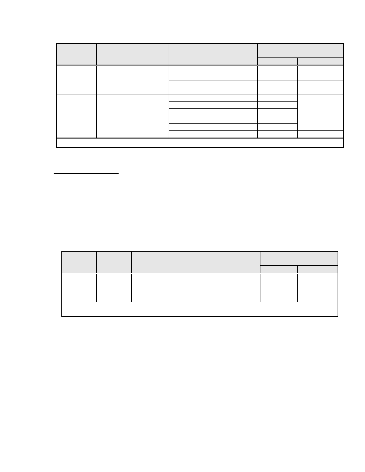
Average Number of Replenishment Rates*
Film Use Films per 8 hrs (ml per 35 x 43 cm)
Processed Condition Of Processor Operation Developer Fixer
MIN-R EV Smart Replenishment
60 sheets or more 90 105
disabled (recommended)
Less than 60 sheets Flooded Flooded
MIN-R EV Smart Replenishment
enabled
260 sheets or more 90
200 sheets 80
150 sheets 70
100 sheets 65
70 sheets 60
Less than 60 sheets Flooded Flooded
* Flooded replenishment is available if needed to maintain sensitometry for very low use conditions.
Smart replenishment should be turned off (refer to Service Bulletin No. 30)
For Length Processors
KODAK X-OMAT Processor Models M35-M, M35A-M, M7B, M7B-E, M6A-N, M6AW , M6B,
M6R
KODAK MIN-R Mammography Processor
• Replenishment takes place whenever film is in the entrance rollers.
• Replenishment rates must be set according to usage and film size(s) fed.
• MIN-R EV Film is fed primary emulsion side down in M35-M, M35A-M, and MIN-R
Mammography Processors.
• For the KODAK Multiloader 700 docked to length replenished processors, mammography
rates are set using 18 cm film travel.
Average Number of Replenishment Rates
Film Film Use Films per 8 hrs (ml per 18 x 24 cm)**
Processed Feeding Condition Of Processor Operation Developer Fixer
MIN-R EV
Single Medium - High
Low
Double Medium - High
Low
60 sheets or more
60 sheets or less*
60 sheets or more
60 sheets or less *
25
Flooded
50
Flooded
Flooded
Flooded
* If flooded replenishment is not used, sensitometry may not stay within control limits.
** Use a single 18 x 24 cm film to set the replenishment rates listed.
Recommended Replenishment Rates
Non-Dedicated Mammography
Non-Dedicated Processing: KODAK MIN-R EV Film can be processed with most current
traditional medical x-ray film. Kodak does not recommend processing Helium Neon and IR films
with KODAK MIN-R EV Film. Use 25 ml/l (3 fl oz per gallon) of KODAK RP X-OMAT Developer
Starter for non-dedicated processing environments. KODAK MIN-R EV Film requires specific
replenishment rates for developer and fixer. These recommendations are guidelines for KODAK
X-OMAT EX II Developer and Replenisher, KODAK RP X-OMAT Developer and Replenisher,
and KODAK RP X-OMAT LO Fixer and Replenisher. Developer and fixer replenishment rates
may require adjustment for specific processing environments. If attempting to use other
manufacturers’ developers and fixers, contact the manufacturer for recommended replenishment
rates.
105
30
60
© Eastman Kodak Company 9/03 Page 4
Page 5
KODAK MIN-R EV Mammography Film Conversion Guide and Processing Recommendations
For Area Processors with Smart Replenishment
KODAK X-OMAT Processor Models 270 RA, 3000 RA, M6RA, 460 RA, 480 RA, 5000 RA
KODAK X-OMAT Multiloader 7000, KODAK X-OMAT Multiloader 300/300 Plus
• Smart Replenishment is enabled by default.
• Replenishment takes place after the equivalent area of a 35 x 43 cm (14 x 17 in.) film has
been fed; therefore, replenishment rates must be set for a 35 x 43 cm (14 x 17 in.) film feed.
•
Additional replenishment occurs automatically during low film usage.
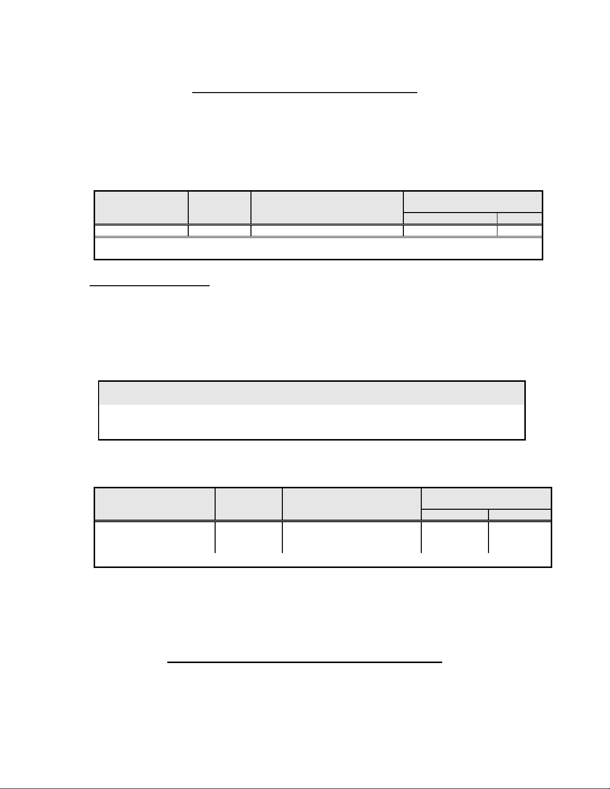
Average Amount of 35 x 43 cm Replenishment Rates
Film Size Use Equivalent Films per (ml per 35 x 43 cm)
Processed Condition 8 hrs of Processor Operation Developer Fixer
All Any Any number * 60 85
* Flooded replenishment should not be needed due to the automatic compensation for use, but it is available if
needed to maintain sensitometry for very low use conditions (fewer than the equivalent of 25 35x43 cm films).
For Length Processors
KODAK X-OMAT Processor Models M35-M, M35A-M, M7B, M7B-E, M6A-N, M6AW , M6B,
M6R
KODAK MIN-R Mammography Processor
• Replenishment takes place whenever film is in the entrance rollers.
• Replenishment rates must be set according to usage and film size(s) fed.
• Film should be fed as recommended in the processor Operator Manual/User Guide.
. Processor Process Min-R EV Primary Emulsion
Up/Down
Min-R Mammography, M35A-M, M35M Down
3000 RA, 270 RA, M7 series Up
M6 B, M6R, 5000 RA, 480 RA, 460 RA Up
• X-OMAT M35M, M35A-M and MIN-R Mammography Processors are not recommended for
roll film
Average Number of Replenishment Rates
Film Size Use Films per 8 hrs (ml per 35 x 43 cm)
Processed Condition Of Processor Operation Developer Fixer
Average size intermix High
Medium
Low
115 sheets or more
40 - 115 sheets
40 sheets or less *
50
65
80
70
85
100
* If flooded replenishment is not used, sensitometry may not stay within control limits.
Flooded Replenishment:
processor quality control with low volume processing. For KODAK MIN-R EV Film, it requires
25 ml/l (3 fl oz per gallon) of KODAK RP X-OMAT Developer Starter in the external
developer replenishment tank.
Flooded replenishment can be used to help maintain stable
Flooded Replenishment Rate Recommendations
• For low use rates, if sensitometry does not stay within control limits, flooded replenishment
may be needed to maintain the developer solution at a continuously fresh chemical activity.
This is accomplished by replenishing not only when film is fed or area accumulated, but also
© Eastman Kodak Company 9/03 Page 5
Page 6
KODAK MIN-R EV Mammography Film Conversion Guide and Processing Recommendations
on the basis of additional replenishment added during the processor on time with an
automatic replenishment timing system.
• When in the flooded mode, developer starter is added to the replenishment tanks at a rate of
89 ml per gallon or 25 ml per liter (3 fl oz per gallon) for MIN-R EV film.
• For detailed information on how to set up each processor for flooded replenishment, see the
appropriate service publication for that processor.
• Qualified service personnel should do the processor setup.
• When filling the developer replenishment or processor tank, add starter according to the table
below.
KODAK Flooded Add Starter?
Developer Mode Replenishment Tank Processor Tank
X-OMAT EX II
RP X-OMAT No No Yes
Yes Yes No*
* Fill the processor tank with chemistry that was mixed in the replenishment tank.
No
Yes
No
Yes
Yes
No*
4. Dryer
Dedicated processors converted to Min-R EV film may be able to reduce the dryer temperature.
An uneven density pattern may be noted if the dryer temperature is too high. Please refer to
Section 7.
• Set the Dryer temperature to the minimum required to produce dry film. Tacky or wet films
occurring even with adjusted Dryer temperatures may indicate that additional service is
required.
• Check that the Dryer Air Tubes are in the correct positions. Remove any dirt from the Dryer
Rollers and Air Tubes, especially the slots.
• Check the settings for correct replenishment.
• Check the replenishment system for kinks in the Tubing, the operation of the Recirculation
and Replenishment Pumps, and the Detector Switches. Change any chemicals that were not
mixed correctly, are exhausted, or are contaminated.
• Check that the Dryer air exhaust is free from any obstructions and is installed correctly
according to the specifications in the installation instructions.
• You may be able to decrease the dryer temperature.
• Should uneven density be noticed, refer to Section 7, evaluating the Imaging Chain for
Uniformity.
© Eastman Kodak Company 9/03 Page 6
Page 7

KODAK MIN-R EV Mammography Film Conversion Guide and Processing Recommendations
General Processor Information
NC = Not Controlled (temperature)
NR = Process Not Recommended for this film type
Processor
Model
gal
M35-M
M35A-M
MIN-R
Mammo
M7B
M7B-E
3000 RA
270 RA
XML300
XML300+
XML7000
M6A-N
M6AW
M6B
M6R
M6RA
460 RA
480 RA
5000 RA
* Fixer temperature may exceed value listed due to internal ambient temperatures in the processor.
** Drop Time is defined as the time from the Lead Edge In (LEI) to the Trail Edge Out (TEO) for a 35 x 43 cm film. (Represents 18 x 24 cm
LEI/TEO)
Approx
Cycle
S 2.25
S 92° F
R
S 2.25
S 94° F
R
S 2.8
S 95° F
R
Devl
Tank
Volume
(L)
(8.3)
2.25
(8.3)
(8.3)
2.25
(8.3)
(10.7)
2.8
(10.7)
Starter
Volume
MIN-R EV
fl oz
(ml)
6.5
(190)
6.5
(190)
6.5
(190)
6.5
(190)
Molded:
8.5 (250)
Stainless
8 (237)
:
8.5
(250)
Dev
°F
(°C)
92° F
(33.3°
C)
(33.3°
C)
94°F
(34.4°
C)
94° F
(34.4°
C)
(34.4°
C)
99° F
37.2°
C
95° F
(35°
C)
(35°
C)
101°
F
(38.3°
C)
Temperature
Fixer*
°F
(°C)
NC 40° - 85° F
NC 40° - 85° F
NC 40° - 85° F
90° F
(32° C)
95° F
(35° C)
NC M6A-N
95° F
(35° C)
Water
°F
(°C)
(4° - 29.4°
C)
(4° - 29.4°
C)
(4° - 29.4°
C)
40° - 85° F
(4° - 29.4°
C)
85° - 90° F
(30°-32.2°C)
M6AW,
:
M6B
40° - 90° F
(4° - 32.2°
C)
40° - 85° F
(4° - 29.4°
C)
:
Transport
Speed
in./min
(cm/min) films/hr seconds seconds
30
(76.2)
30
(76.2)
42
(106.7)
42
(106.7)
57
(144.8)
66
(167.6)
66
(167.6)
99
(251.5)
Capacity
35 x 43
cm (18 x
24 cm)
94
(145)
(145)
146
(250)
148
(250)
201 19 82
229
(393)
233
(393)
351 16 60
Approx
Devl
Time
33 150
33 150
25 112
27 120
26 111
25 90
24 95
Approx
Drop Time**
35cm length
(24cm
length)
(135)
(135)
(101)
(116)
(104)
(86)
(89)
5. Processor Quality Control Operating Levels
The following instructions are recommendations for the control of the processor quality. Different
sensitometric parameters will be monitored (MD: mid-density/speed, DD: density
difference/contrast, B+F: base+fog/gross fog). You can modify these different parameters based
on local regulations or guidelines.
Processor Control Aims
a. Using a Sensitometer, expose and process a Sensitometric strip. Repeat this exposure
and processing once each day for five consecutive days. For large volume processing
tanks or very low film volume a 10 day average may be used. For the
Control Sensitometer and X-rite models 394 and 396, the following Dip Switch settings
are recommended for KODAK MIN-R EV Film:
• SINGLE and GREEN settings at Exposure Setting No. 4
• 1-down, 2-down, 3-up, 4-down
© Eastman Kodak Company 9/03 Page 7
KODAK Process
Page 8

KODAK MIN-R EV Mammography Film Conversion Guide and Processing Recommendations
− Using a lower exposure setting will decrease the optical density, using a
higher exposure setting will increase the optical density.
For other manufacturers, follow the recommendations for optimum mammographic results
(optimized green, single emulsion).
b. Read and record the densities of each step of the sensitometric strip using the
densitometer, including an area of processed film that has not been exposed.
c. From the five strips, determine the average of the densities for each step using the
respective densities for each step.
d. Determine which step has an average density closest to 1.20 but above 1.0. Designate
this step as the mid-density (MD)/speed step. Tolerance +/- 0.10-0.15
e. Determine which step has a density closest to 2.20 and which step has a density closest
to but not less than 0.45. The difference in densities between these two steps should be
designated as the density difference (DD)/contrast. Tolerance +/- 0.10-0.15
f. Determine the average of the densities from the unexposed area of the five strips. This
density will be designated as the base-plus-fog level (B+F)/gross fog of the film.
Tolerance < 0.25
g. Start a new Processor quality control chart and record the numerical values of the MD
(speed), DD (contrast) and B+F (gross fog) on the centerline of the appropriate areas of
the control chart.
Baseline Operating Level (on the day of conversion)
a. Using a Sensitometer, expose and process five (5) sensitometric strips at the same time
and on the same side of the processor.
b. Read and record the densities of each step of the sensitometric strip using the
densitometer, including an area of processed film that has not been exposed.
c. Determine the average of the densities for each step using the densities for that step
from the five strips.
c. Determine which step has an average density closest to 1.20. Designate this step as the
mid-density (MD)/speed step.
e. Determine which step has a density closest to 2.20 and which step has a density closest
to but not less than 0.45. The difference in densities between these two steps should be
designated as the density difference (DD)/contrast.
f. Determine the average of the densities from the unexposed area of the five strips. This
density will be designated as the base-plus-fog level (B+F) of the film.
g. Start a new Processor quality control chart and record the numerical values of the MD
(speed), DD (contrast) and B+F on the centerline of the appropriate areas of the control
chart.
These can be used as the baseline operating aims until the five-day averaging has been
completed.
6. Automatic Exposure Control (AEC)
The desired optical density and operating kVp preference should be established. Refer to the
KODAK MIN-R EV Film System Mammography User Guide (KODAK Publication # , Cat # )
for a procedure to establish kVp and optical density for MIN-R EV Film.
Auto AEC/Phototimer recalibration is recommended after processing has stabilized
Customers should consult their x-ray equipment manufacturer to ensure proper recalibration. If
this is not performed at the time of conversion, then an interim AEC photo-timer adjustment
should be determined. Using the appropriate tissue equivalent phantom, adjust the density
control setting to achieve the desired optical density for the new screen/film system.
significant difference in the curve shape of Min-R EV film, optimum results for all breast
types may not be achieved if the mammography x-ray unit is NOT calibrated for Min-R EV.
.
Due to the
Note: aims of the phantom QC should be adjusted once the calibration is performed if optical
density or density difference change
.
© Eastman Kodak Company 9/03 Page 8
Page 9

KODAK MIN-R EV Mammography Film Conversion Guide and Processing Recommendations
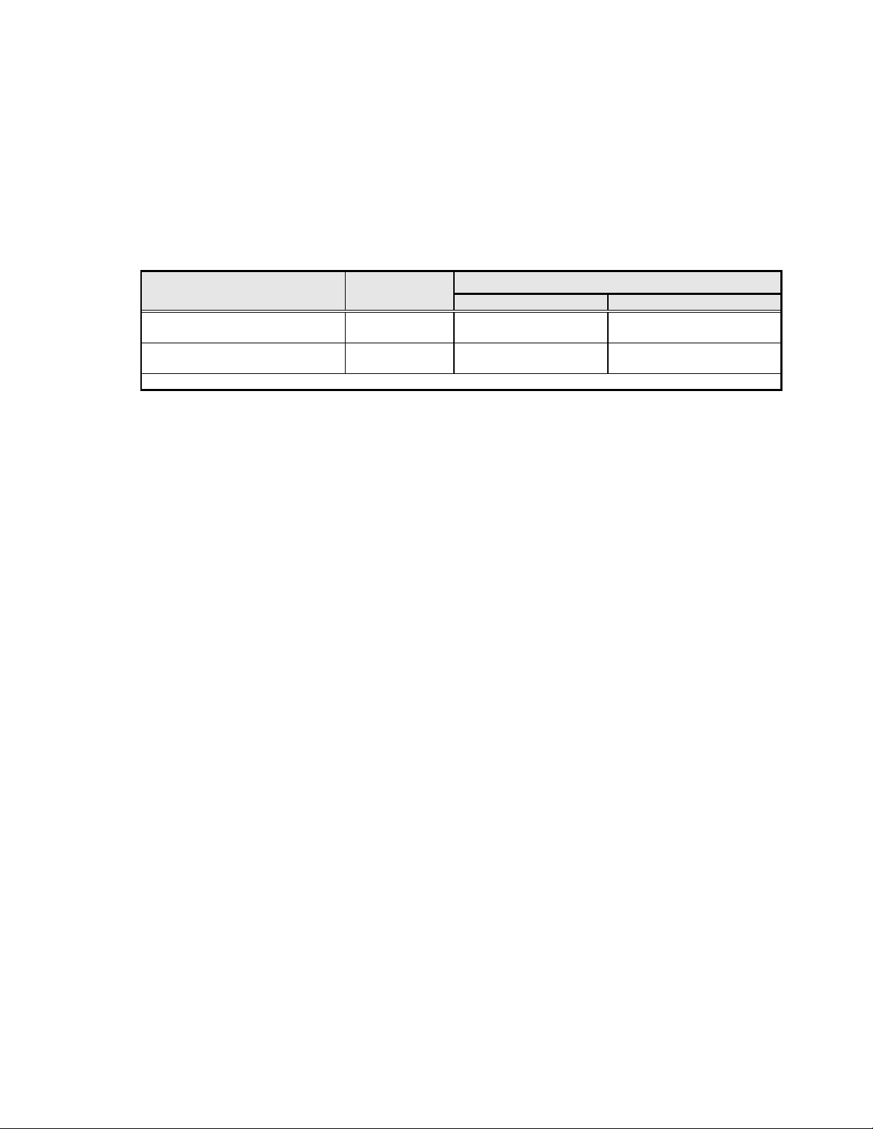
The following table shows system speeds for KODAK MIN-R EV Film with KODAK MIN-R EV
Screens, and may be useful in determining an interim AEC adjustment.
Speed Contrast Comparisons for KODAK Mammography Film
Relative
Cycle
MIN-R EV EV 150 Standard/Rapid 150 4.5 4.7 >4.5
MIN-R EV EV 190 Standard/Rapid 190 4.5 4.7 >4.5
MIN-R 2000 2000 Standard 150 3.60 3.80 >4.0
MIN-R 2000 2190 Standard 190 3.60 3.80 >4.0
MIN-R 2000 MIN-R Standard 100 3.60 3.80 >4.0
MIN-R L 2000 Standard 150 3.40 3.60 >4.0
MIN-R L 2190 Standard 190 3.40 3.60 >4.0
MIN-R L MIN-R Standard 100 3.40 3.60 >4.0
1 Relative speed determined from matched-density radiographs of a mammography phantom. KODAK MIN-R M Film and
MIN-R Screen arbitrarily assigned a relative speed of 100.
2 Contrast was measured as the average gradient between densities 0.25 and 2.00 above gross fog using inverse square
sensitometry
Speed
Contrast Film Screen Processing
RP EX II
D-Max
While system speeds may be similar, screen absorptions are different. Equipment
adjustment will be necessary.
7. Evaluating the Imaging Chain for Uniformity
Description:
• Pattern of plus or minus density
• May appear either as a band or a diffuse region
• Readily seen on a flat field or phantom, rarely in the clinical image
• Can appear across the image, but seen most often in a uniform phantom along the chest
wall side of the image
Picture:
Probable Cause or Causes:
The density pattern may be caused by a combination of factors in the exposing and processing of
the film.
• Grid/cassette holder
o Grid motor
o Grid artifact/defect
o Carbon fiber top damage
• Dryer
© Eastman Kodak Company 9/03 Page 9
Page 10

KODAK MIN-R EV Mammography Film Conversion Guide and Processing Recommendations
o Dryer temperature too high
o Air tubes blocked or obstructed
o Buildup on dryer rollers
o Squeegee rollers
o Dryer venting
• Processor
o Hesitation in developer rack
o Stubbing in developer rack
o Processor type
Some processors have a better path through the developer, wash and
dryer (e.g. Min-R Mammography or X-OMAT 5000 RA processor)
Note: In deep tank processors, test films should be processed emulsion
up and down to determine best orientation for uniformity.
Films must be processed emulsion down in X-OMAT M35M, M35A-M
and Min-R Mammography processors.
• Chemistry
o Type and/or quality of the chemistry
Mixed and replenished properly
Note: High contrast developers may increase the visualization of breast structure.
Consequently, they may also enhance the visualization of any anomalies present in
the imaging chain. The visualization of grid and dryer patterns may be more
pronounced with these developers.
Isolating Non-Uniformity
Step 1. Determine if the artifact is coming from the processor or the X-ray exposure
equipment
Equipment Needed
• 1 inch (2cm) thick uniform sheet of acrylic or Lucite
• Cassette with known good screen-film contact
The following procedure may be used to make this evaluation:
• Expose films to an optical density of 1.10 to 1.50, using the same cassette and the uniform
sheet of acrylic.
—The exposure time used should be at least 0.5 seconds or longer to eliminate grid
artifacts caused by too short an exposure time.
—The cassette must be known to have good screen-film contact.
• Process one film so that the narrowest dimension of the film is the leading edge; process
a second film so that the widest dimension of the film is the leading edge.
• Once processed, view the film pairs (or single films) in the same orientation as
processed.
• Artifacts that are parallel to each other on a film pair occurred in the processor
(artifacts may be parallel or perpendicular to film travel).
Artifacts that are perpendicular to each other on a film pair occurred during exposure from the
x-ray unit.
© Eastman Kodak Company 9/03 Page 10
Page 11

KODAK MIN-R EV Mammography Film Conversion Guide and Processing Recommendations
Artifacts that are parallel to each other are caused by
the processor; artifacts that are perpendicular are
caused during exposure.
If the artifact is processor caused:
• Lay the film on the film feed tray in the
darkroom, and mark an arrow (↑) on
the corner of the film with a lead pencil
immediately before processing to
indicate the direction of film travel.
• It is also helpful to mark the emulsion
orientation (up [U] or down [D]), as
well as which side of the processor
feed tray (right [R] or left [L]) is being
used, when feeding the film into the
processor, e.g., ↑UR (emulsion up,
Note that processors in which MIN-R EV Mammography film will be processed should be
evaluated initially to determine whether films should be processed emulsion side up or emulsion
side down--which orientation provides the best uniformity and the fewest artifacts--before
processing clinical and quality control films.
• To thoroughly evaluate the entire processor, up to ten films should be exposed and
processed as described above: one pair emulsion side up on the right side of the film
right side feed tray)
© Eastman Kodak Company 9/03 Page 11
Page 12

KODAK MIN-R EV Mammography Film Conversion Guide and Processing Recommendations
feed tray, one pair emulsion up on the left side of the feed tray, one pair emulsion side
down on the right side of the film feed tray, and one pair emulsion side down on the left
side of the film feed tray.
• Expose the first two film pairs that will be processed as described above (emulsion side
up on right, emulsion side up on left) using the small moving grid device (18 x 24 cm
bucky) and use to evaluate whether artifacts are being generated by the x-ray unit in
conjunction with the small bucky.
• Careful analysis of all of the films will indicate whether emulsion side up or down gives the best
overall processing results.
• the protocol should subsequently be posted in the darkroom so all films are processed
consistently.
• All clinical images, sensitometric strips, and phantom images emulsion side
up or all emulsion side down.
• Determine which side of the processor and which orientation (emulsion up or down)
gives the best uniformity.
Film must be processed emulsion side down in the MIN-R Mammography, X-OMAT M-35AM,
and X-OMAT M-35M Processors. (Multiloaders may be excluded as film orientation during
processing is fixed.)
• Quality control films (phantom images and sensitometric strips) should also be
processed in a specific location with respect to the film feed tray (right side or left side,
with the edge of the film butted against the guide of the film feed tray).
Determine how much of the non-uniformity pattern is coming from the grid. Changes made to
the processor will not be able to improve upon this.
• Expose with and without the grid.
o Expose one film as normal and process emulsion side down on the non-gear
side of the processor.
o Make a table top exposure (set the loaded cassette on top of the table, place the
Lucite on top and make the exposure) and process emulsion side down on the
non-gear side of the processor.
Please contact the equipment manufacturer if the pattern is noticeable.
© Eastman Kodak Company 9/03 Page 12
Page 13

KODAK MIN-R EV Mammography Film Conversion Guide and Processing Recommendations
With grid—note non-uniform
pattern
Without grid
Please record your results in Section 1 of the Troubleshooting Non-Uniformity worksheet.
Step 2. Test the ventilation of the processor by following the procedure outlined below
Failure to properly vent the processor or multiloader exhaust can cause corrosion inside the
equipment (and any interfaced equipment) and can increase the probability of film artifacts.
Venting according to the specifications outlined in this bulletin will help minimize these problems.
Some equipment (like the KODAK X-OMAT 5000 RA Processor) may have different procedures
and specifications for exhaust measurement. Service documentation for a particular piece of
equipment always takes precedence over these recommendations.
Items Needed
1. Air Meter (TL-2431).
The above item can be ordered through Service Parts Management at 800-431-7278 (U.S.) or
585-724-7278 (Outside U.S.).
STEP ACTION
Make sure the processor/multiloader exhaust hose is connected to the building
1
exhaust system. Disposal of effluent air must comply with prevailing environmental
codes.
2 Power down the processor/multiloader.
3 Disconnect the exhaust hose from the rear of the equipment.
4
Connect the rubber hose on the Air Meter’s center connector.
5 Connect the L Tube to the rubber hose.
6
7
Make a 6.4 mm (1/4 in.) hole approximately 30.5 cm (12 in.) from the end of the
exhaust hose that will be connected to the processor.
Insert the L Tube into the hole (Step 6) so the end of the L Tube is flush with the
inside of the exhaust hose and perpendicular to the wall of the exhaust hose.
Important: Do not connect the exhaust hose to the processor when checking negative static
pressure.
© Eastman Kodak Company 9/03 Page 13
Page 14

KODAK MIN-R EV Mammography Film Conversion Guide and Processing Recommendations
Procedure: Measuring the Static Pressure
Step Action
1 Hold the air meter vertically to assure the greatest accuracy. Make sure the meter tubing
is not kinked.
2 Record the average of several readings.
3 Compare the average reading with the information in the table below (Measuring the
Static Pressure).
Important: The negative airflow in the processor exhaust duct must remain constant
when the processor is in the run, standby, and shut-down mode; therefore, the building
exhaust system must be on 24 hours a day and have the same negative airflow
throughout the day.
4 If the average reading is not within the tolerances specified in the table, adjust the Air Gap
Assembly to obtain the tolerances. If the tolerances still cannot be obtained and you must
exceed the maximum in order to obtain the correct negative static pressure, contact site
management personnel to have the building exhaust corrected.
Important: There must be an adequate air gap (maximum 5.08 cm / 2 inches) between
the processor exhaust hose and the building exhaust to prevent positive airflow from
flowing back into the processor. If the building exhaust venting system cannot meet
specifications, an Auxiliary Ventilation Fan Kit can be ordered through Service Parts
Management.
5 Reconnect the exhaust hose to the processor.
Measuring the Static Pressure
Negative Static Pressure of Water Head Duct Diameter
Minimum Maximum
76 mm (3 in) 0.76 mm (0.03 in.) 1.02 mm (0.04 in.)
102 mm (4 in.) 0.25 mm (0.01 in.) 0.51 mm (0.o02 in.)
© Eastman Kodak Company 9/03 Page 14
Page 15

KODAK MIN-R EV Mammography Film Conversion Guide and Processing Recommendations
(
Additional Notes
If the processor/multiloader is installed in a darkroom wall opening, the darkroom air pressure
must exceed the air pressure of the area outside the darkroom. This will:
• Prevent air from cascading through the processor and into the darkroom area.
• Assure correct dryer venting.
• Minimize chemical fume and vapor containment inside the processor and its dryer exhausting
system.
• Reduce film artifacts in the out-of-solution transport roller sections.
• Reduce corrosion of the processor/multiloader.
Room Ventilation
The room must have a minimum of 10 air exchanges each hour
Record your results in Section 2 of the Troubleshooting Non-Uniformity worksheet.
Step 3. Having ruled out the x-ray unit and grid and the ventilation as causes of the uneven
density, look at the films by reflected light to see if the uneven density pattern is visible.
To rule out the dryer as a cause, expose several additional flat field films, following the procedure
above. Process the first film in the orientation that gave you the best results in step 1 and catch it
as it exits the wash rack prior to entering the dryer section. Let it air dry.
.
The dryer pattern exhibited on the left is
visible by both reflected and transmitted light.
It may be minimized by following the
recommendations on pages 15-16 of this
document.
Examine the film to see if the non-uniformity changes. If it does, then follow the corrective actions
for dryer pattern. Record your results in Section 3 of the Troubleshooting Non-Uniformity
Worksheet.
Step 4. If the uneven density pattern does not change in step 3, try to isolate which rack in
the processor it may be occurring.
Record your results in Section 4 of the Troubleshooting Non-Uniformity worksheet.
Corrective Action (according to cause):
Symptom Cause Corrective Action
Grid non-uniformity
Shoreline Artifacts
visible in both transmitted
Dryer Temperature too high Turn down dryer temperature as
Contact your x-ray equipment
manufacturer.
low as possible to dry the film.
© Eastman Kodak Company 9/03 Page 15
Page 16

KODAK MIN-R EV Mammography Film Conversion Guide and Processing Recommendations
and reflected light)
Hesitation Marks/stub lines
(visible in transmitted light)
As per the guidance on page 255 of the ACR’s Mammography Quality Control Manual 1999 “If
significant film processor artifacts are detected, contact the person maintaining the processor or
the film processor service organization or dealer. Contact the X-ray equipment service person for
suggestions on additional testing procedures and for help in correcting X-ray equipment artifacts.
Gentle cleaning may be able to eliminate cassette or screen artifacts. Not all artifacts can be
totally eliminated. It may be helpful to use the concept of ALARA (as low as reasonably
achievable) when attacking artifacts. If they can be easily eliminated, they should. If the artifact is
difficult or expensive to eliminate and is subtle (not mimicking or obscuring clinical information), it
Air tubes blocked or obstructed Clean air tubes (Check at each
PM or as needed)
Try rotating several air tubes by
180 degrees
Wash rack squeegee rollers Squeegee rollers must be clean
and in good working order.
(Check imperfections, spring
pressure, smooth rotation, etc.)
Poor ventilation Check the ventilation as per
procedure in Service Bulletin
No. 101.
Improperly mixed, underreplenished developer and fixer
Change in velocity of the film
travel resulting from interference
within the film path
Malfunctioning rack or drive
component (roller, gear, chain,
drive motor or sprocket)
Incorrectly assembled or
damaged guide shoes
Guide Shoes out of adjustment
or out of alignment
Chemical buildup on rollers Inspect all rollers for dirt and
Warped or rough rollers
Worn roller bearings, shafts and
sideplates
Idler rollers not turning Adjust rack chains
Damaged gear or gudgeon
Improperly mixed or depleted
developer and/or fixer
Review mixing procedures
Verify that the replenishment
rates are set appropriately (as
per Service Bulletin No. 30
recommendations).
Repair or replace rollers,
bearings, shafts, sideplates,
gears, gudgeons and guide
shoes
Check that the guide shoes are
not loose and are positioned in
the correct direction
Check that the developer rack
and developer/fixer crossover
are assembled correctly
buildup of dried chemicals.
Clean the rollers according to
manufacturer’s
recommendations.
Check that the sideplates of the
guide shoes are correctly
oriented
Review mixing procedures
Verify that the replenishment
rates are set as per Service
Bulletin No. 30
recommendations.
© Eastman Kodak Company 9/03 Page 16
Page 17

KODAK MIN-R EV Mammography Film Conversion Guide and Processing Recommendations
may be tolerable. The medical physicist should consult with the interpreting physician as to
whether the artifact is tolerable.”
Troubleshooting Non-Uniformity Worksheet
Section 1). Determine if the artifact is coming from the processor or the X-ray exposure
equipment
After completing the tests on pages 10-12, please compare the test films and record your
results below:
Grid versus non bucky comparison: ________________________________________________
Emulsion Up versus Emulsion Down comparison: _____________________________________
Non-gear versus gear side of processor: _____________________________________________
Section 2). Determine the ventilation of the processor
Record your results and compare to Kodak’s recommendations on page 14:
Negative static pressure: _________ Results within Kodak’s recommendations? Y N
Section 3) Ruling out the dryer as a cause of the uneven density pattern
Perform the test as outlined on page 15.
Examine the resulting films to see if the uneven density pattern changes.
Record your results:
Did the dryer pattern change? Yes No
If it does, then follow the corrective action for dryer pattern on page.
Section 4) If the uneven density pattern does not change, try to isolate which rack in the
processor in which it may be occurring.
Results:
Pattern was isolated in the: developer rack fixer rack wash rack
Could not isolate pattern.
If you cannot isolate the cause of the pattern, please send a copy of this form, your test films and
the completed Information Needed by Kodak to Facilitate Troubleshooting form to:
Eastman Kodak Company
Health Imaging Technical Support
343 State Street
Rochester, NY 14650-1131
© Eastman Kodak Company 9/03 Page 17
Page 18

KODAK MIN-R EV Mammography Film Conversion Guide and Processing Recommendations
8. Other Mammography Quality Control Tests
• Emulsion Log
See KODAK MIN-R EV Film System User Guide (KODAK Publication #, Cat #).
• Phantom Image Evaluation
Perform the test as described in the Mammography Quality Control Manual for
Radiologists, Medical Physicists, and Technologists, American College of Radiology
1999 (ACR QC Manual) page 258.
• Note any changes in the number of test objects seen. Re-establish the baseline
numbers.
• The density difference on the phantom may be significantly higher due to the high
contrast of KODAK MIN-R EV Film.
• Darkroom Fog Test
Perform the test as described in the KODAK MIN-R EV Film System User Guide
(KODAK Publication # , Cat # ). Please note that a 7.5 watt bulb is recommended with
KODAK mammography film.
• Analysis of Fixer Retention in Film
Perform the test as described in the KODAK MIN-R EV Film System User Guide
(KODAK Publication # , Cat # ).
The conversion to MIN-R EV Film includes a conversion to new KODAK MIN-R EV
Screens. The following tests should be performed:
• Screen-Film Contact
Perform the test as described in the KODAK MIN-R EV Film System User Guide.
• Uniformity of Screen Speed
Perform the test as described in the KODAK MIN-R EV Film System User Guide
(KODAK Publication #, Cat # ).
For More Information:
Outside U.S. please contact your local Kodak representative.
U.S. Distributors Contact:
Health Imaging
Technical Support
1-800-328-2910 (option 1 for faxback)
CES Personnel Contact:
Film Handling TAC
U.S.: 1-800-328-2910
Canada: 1-800-433-1414
Kodak, MIN-R, and X-OMAT are trademarks.
Eastman Kodak Company, 2003
© Eastman Kodak Company 9/03 Page 18
 Loading...