

Kodak I810 - Scanner Firmware - PC, Scanners i800 Series, I820, I830, I840 User Manual
...
i800 Series Scanners
A-61169
Part No. 9E3959
CAT No. 129 5237
User’s
Guide
Safety and Installation Information for the Kodak i800 Series Scanners
IMPORTANT: Equipment shall be installed by qualified personnel.
WARNING: Dangerous voltage. Disconnect the main power before installation.
WARNING: Before changing a lamp, always power down the scanner and let it cool a minimum
of 10 minutes before proceeding (see Warning Labels below).
CAUTION:
POZOR: Horký povrch -- nedotýkat se
DIKKAT:
CAUTION
POZOR:
DIKKAT: Sicak yüzey, dokunmayin
Hot surface, avoid contact
Hareketli parçalar, dokunmayin
: Moving parts, avoid contact
Pohybující sečástie -- nedotýkat se
User Precautions
Users and their employer need to observe the common sense precautions applicable to the operation of
any machinery. These include, but are not limited to, the following:
• Do not wear loose clothing, unbuttoned sleeves, etc.
• Do not wear loose jewelry, bracelets, bulky rings, long necklaces, etc.
• Hair length should be kept short, using a hair net if needed, or tying long hair up in a bundle.
• Remove all other loose objects from the area that could be drawn into the machine.
• Take sufficient breaks to maintain mental alertness.
• Follow the recommended Kodak cleaning procedures. Do not use air, liquid or gas spray cleaners.
These cleaners only displace the dust, dirt or debris to another location within the scanner, which
could cause the scanner to malfunction.
Supervisors should review their practices and make compliance with these precautions a part of the job
description for operation of the Kodak i800 Series Scanners or any mechanical device.
ElectroMagnetic Compatibility Statements
European Union
This is a Class A product. In a domestic environment this product may cause radio interference in which
case the user may be required to take adequate measures.
United States
This equipment has been tested and found to comply with the limits for a Class A digital device, pursuant
to part 15 of the FCC rules. These limits are designed to provide reasonable protection against harmful
interference when the equipment is operated in a commercial environment. This equipment generates,
uses and can radiate radio frequency energy and, if not installed and used in accordance with the
instruction manual, may cause harmful interference to radio communications. Operation of this equipment
in a residential area is likely to cause harmful interference in which case the user will be required to
correct the interference at their own expense.
January 2005 1

Taiwan
Japan Class A
This equipment is in the Class A category (Information Technology Equipment to be used in commercial
and/or industrial areas) and conforms to the standards set by the Voluntary Control Council for Interference
by Information Technology Equipment aimed at preventing radio interference in commercial and/or
industrial areas.
Consequently, when used in a residential area or in an adjacent area thereto, radio interference may be
caused to radio and TV receivers, etc.
Read the instructions for correct handling.
Peoples Republic of China Class A
January 2005 2

Table of Contents
1 Introduction ......................................................................1-1
Product description ............................................................ 1-2
Standard features ..............................................................1-2
Standard configurations..................................................... 1-3
Transport speed................................................................. 1-3
Speeds and resolutions .....................................................1-3
Scanner specifications....................................................... 1-4
Dimensions ..................................................................1-4
Minimum clearances .................................................... 1-4
Acoustic noise.............................................................. 1-4
Electrical ......................................................................1-4
Power system connection ............................................ 1-4
Environmental .............................................................. 1-4
External components ......................................................... 1-5
Back of scanner ................................................................. 1-5
Environmental information and equipment disposal ..........1-6
2 Using the Scanner ...........................................................2-1
Turning on the scanner...................................................... 2-1
Document preparation .......................................................2-2
Acceptable document materials.........................................2-3
Recommended paper weights ...........................................2-3
Acceptable document sizes ............................................... 2-3
Maximum document batch height for automatic feeding ...2-4
Downward and upward curl documents.............................2-4
Adjusting the side guides on the input tray ........................ 2-4
Adjusting the output tray .................................................... 2-5
Scanning documents .........................................................2-6
Loading long documents in the feeder............................... 2-7
Continuous and manual feeding ........................................ 2-7
Feeding thick documents................................................... 2-8
A-61169 January 2005 i

3 Operator Control Panel Functions .................................3-1
Enabling and disabling the scanner................................... 3-2
Enabling the scanner ...................................................3-2
Disabling the scanner ..................................................3-3
Navigating through the functions on the control
panel menu ..................................................................3-4
Accessing information........................................................ 3-5
Lowering the elevator tray..................................................3-5
Using the Diagnostics Settings menu ................................ 3-5
Performing a self-test or extended self-test .................3-6
Running in count-only mode ........................................3-6
Performing a print test.................................................. 3-7
Performing a patch test................................................ 3-8
Using the Settings menu....................................................3-9
Changing the alarm volume ......................................... 3-9
Changing the display contrast.................................... 3-10
Changing the SCSI ID................................................ 3-10
Changing the SCSI termination .................................3-11
Setting the elevator tray position................................ 3-12
Calibrating the scanner.................................................... 3-13
Jogging the transport ....................................................... 3-14
Programmable key assignments......................................3-14
4 Document Printer and Patch Reader .............................4-1
The Document Printer........................................................4-1
Printing information ...................................................... 4-1
Horizontal print position ...............................................4-3
Purging the ink cartridge ..............................................4-4
Replacing the ink cartridge ..........................................4-5
Replacing the ink blotter strips..................................... 4-7
Setting the printer position ...........................................4-9
The Patch Reader............................................................4-10
Patch types ................................................................4-10
Patch code placement ...............................................4-11
Setting the Patch Reader position .............................4-12
ii A-61169 January 2005

5 Maintenance ..................................................................... 5-1
Cleaning the paper path.....................................................5-1
Cleaning the upper transport area ..................................... 5-2
Cleaning the vertical transport area ................................... 5-5
Cleaning the transport area ...............................................5-6
Cleaning the printer and patch head.................................. 5-9
Cleaning the imaging guides............................................5-10
Maintenance and replacement procedures......................5-11
Replacing the feed module and feed module tires...........5-12
Replacing the feed module ........................................5-13
Replacing the feed module tires ................................5-13
Separation roller and tires................................................5-15
Replacing the separation roller ..................................5-15
Replacing the separation roller tires ..........................5-16
Changing the separation pad........................................... 5-16
Cleaning the feed module tires and separation roller
roller tires ...................................................................5-17
Replacing lamps ..............................................................5-17
Replacing the imaging guides..........................................5-20
Customizing the side guides for self-centering feeding ...5-21
Changing the output tray side guides ..............................5-23
Ordering supplies.............................................................5-25
6 Troubleshooting/Messages ............................................ 6-1
Clearing the document path...............................................6-1
Message Listing................................................................. 6-5
Document sensor location ...............................................6-10
Problem solving chart ......................................................6-11
A-61169 January 2005 iii

1 Introduction
This User’s Guide provides information and operator procedures for the
Kodak i800 Series Scanners. The information in this guide is for use with
all of the i800 Series Scanners unless otherwise noted.
Chapter 1, Introduction provides general information about the i800
Series Scanners including a product description, features and benefits,
specifications, an overview of external components and user precautions.
Chapter 2, Using the Scanner includes information on how to
prepare your documents for scanning, elevator tray and output tray
adjustments, turning the scanner on and off and how to scan documents.
Chapter 3, Operator Control Panel Functions provides a list of the
icons found on the Operator Control Panel and what functions can be
performed using the Operator Control Panel.
Chapter 4, Document Printer and Patch Reader provides
instructions for using and changing the location of the Document Printer 1
and the Patch Reader. This chapter also instructs how to change and
purge the ink cartridge.
Chapter 5, Maintenance provides complete maintenance procedures
for the i800 Scanner, including replacement procedures for the feeder
module and tires, separation roller and tires, exposure lamps and imaging
guides.
Chapter 6, Troubleshooting/Messages provides a message listing, a
problem solving chart and how to clear a document jam.
A-61169 January 2005 1-1

Product description
Standard features
The Kodak i800 Series Scanners are ideal for operation with bi-tonal
and/or color/grayscale documents, documents with shaded backgrounds
or foregrounds, and mixed document sets. These scanners offer a new,
user interface and Kodak-patented technologies that produce high quality
production images.
The following features are standard on the Kodak i800 Series Scanners.
• Simultaneous output of color/grayscale and bi-tonal images (i820 and
i840 scanners only)
• SurePath paper handling, featuring:
– 1,000-sheet QuickSet elevator that automatically returns to the
batch level you set
– Automatic feeder with single-sheet feeding and operator-assisted
document stacks. Allows you to set the elevator level to
accommodate 25-, 250- 500-, 750- 1000-document stacks
– 3D Multi-feed Detection, using ultrasonic technology, offering
outstanding reliability
– Flexible document feeding center- and edge-aligned
– An adjustable output tray that handles documents of varying sizes
• The Tri-Color Plus Array provides, in one pass, true color and bi-tonal
images
• Zone Processing allows operator selection of a fixed subsection or
zone (i820 and i840 scanners only)
• PerfectPage, now with iThresholding (color/grayscale and bi-tonal)
• Built-in iThresholding, Adaptive Threshold Processing (ATP), image
compression, despeckle, error diffusion, and dithering for bi-tonal
scanning
• Electronic Color Dropout
• Color on-the-fly
• Accepts custom color tables
• A wide variety of image output resolutions in bi-tonal and
color/grayscale are available
• Easily upgradeable models, at your site, with minimal downtime
• Bundled ISIS and TWAIN drivers
• Friendly operator interface only seven operator control buttons
• Ease-of-use easy replacement of consumables
• Illumination tracking with calibration alert
• Diagnostics and modular design simplify service and minimize
downtime
• Image address with Patch Reader support
• Document Printer 1 imprinting on scanned documents
1-2 A-61169 January 2005

Standard
configurations
Transport speed
Four models of the Kodak i800 Series Scanners are available:
• Kodak i810 Scanner (bi-tonal) provides bi-tonal scanning with
throughput speeds up to 120 ppm
• Kodak i820 Scanner provides color/grayscale and bi-tonal
scanning simultaneously with throughput speeds up to 120 ppm
• Kodak i830 Scanner (bi-tonal) provides bi-tonal scanning with
throughput speeds up to 160 ppm
• Kodak i840 Scanner provides color/grayscale and bi-tonal
scanning simultaneously with throughput speeds up to 160 ppm
Following is the minimum and maximum paper transport speed and
capacity of the scanner:
Dimension Minimum Maximum Operational Mode
Length 6.4 cm (2.5 in.) 27.9 cm (11 in.) Auto-feed
Length 27.9 cm (11 in.) 43.2 cm (17 in.) Auto-feed with extensions
Length 43.2 cm (17 in.) 76.1 cm (30 in.) Operator assistance
Width 6.4 cm (2.5 in.) 8.9 cm (3.5 in.) Operator assistance
Speeds and
resolutions
Scanner Throughput
Width 8.9 cm (3.6 in.) 30.5 cm (12 in.)* Auto-feed
* The scanner transport will allow feeding a 30.5 cm (12-inch)-wide
document but will only scan an area of 29.7 cm (11.7 inches) in width.
The chart below provides speeds and resolutions for the i800 Series
Scanners:
Speed (ips) Bi-tonal
(ppm)
i810 120
80
45
i820 120
80
45*
i830 160
106
60
i840 160
106
60*
21
14
14
21
14
14
28
18.67
18.67
28
18.67
18.67
Resolution (dpi)
200
300, 240
400
200
300, 240
400
200
300, 240
400
200
300, 240
400
Color/Grayscale
Resolution (dpi)
N/A
200, 150, 100
200, 150
200
N/A
N/A
N/A
200, 150, 100
300*, 200, 150, 100
300, 200
* Throughput at these settings may vary based on system limitations.
A-61169 January 2005 1-3

Scanner specifications
Dimensions
Minimum clearances
Front Rear Right Side Left Side Top
Normal
Operation
Maintenance
N/A 4 in.
40 in.
102 cm
Following are the dimensions and clearances for the Kodak i800 Series
Scanners:
Height: 124 cm (49 in.)
Width: 66 cm (26 in.)
Depth: 127 cm (50 in.)
Weight: 204 kg (450 lbs) including packaging
188 kg (414 lbs) without packaging
The table below provides the minimum clearances for normal operation
and maintenance of the i800 Series Scanners:
10 cm
4 in.
10 cm
4 in.
10 cm
24 in.
61 cm
4 in.
10 cm
4 in.
10 cm
10 in.
25 cm
24 in.
61 cm
Acoustic noise
Electrical
Power system
connection
Environmental
• Operator position standby mode:
– Sound Pressure Level (L
): 39.8 dB(A)
A
• Operator position full system operating mode:
– Sound Pressure Level (L
– Instantaneous Peak Values >
• Sound Power Level (L
WA
): 65.4 dB(A)
A
):
130 dB(C) None
– Standby 56.4 dB(A)
– Full System 72.0 dB(A)
NOTE: All data was measured in accordance with DIN 45635, ANSI
S12.10-1985, and ISO 7779 in a hemi-anechoic chamber.
100 – 127 V, 6.5 A, 50/60 Hz
200 – 240 V, 3.5 A, 50/60 Hz
This product is also designed for Norwegian IT power system with phaseto-phase voltage 230V.
Temperature: 15 to 35°C (59 to 95°F)
Humidity: 15 to 76% (dry bulb)
Altitude: up to 8000 feet (2438 meters)
1-4 A-61169 January 2005
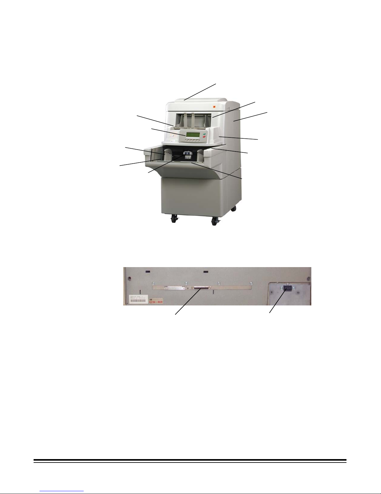
External components
Operator control panel
Side guides
Elevator tray
See the illustration below for the location of the external components of
the scanner.
Top cover
Swing out door
Output tray
Feed module
Feeder extensions
Bi-fold door
Power switch
Gap release lever
Back of scanner
SCSI Connector
Power cord
connector
A-61169 January 2005 1-5

Environmental
information and
equipment disposal
• The Kodak i800 Series Scanners are designed to meet worldwide
environmental requirements.
• Guidelines are available for the disposal of consumable items that are
replaced during maintenance or service; follow local regulations or
contact Kodak locally for more information
• The product packaging is recyclable.
• Parts are designed for reuse or recycling.
• The Kodak i800 Series Scanners contain lead in the circuit boards
and mercury in the lamps. Disposal of these materials may be
regulated due to environmental considerations. For disposal or
recycling information, please contact your local authorities or visit the
Electronics Industry Alliance website: www.eiae.org.
1-6 A-61169 January 2005
2 Using the Scanner
This chapter provides the following operational procedures:
• Turning on the scanner
• Document preparation
• Adjusting the input tray, side guides and output tray
• Scanning documents
• Feeding long documents
• Continuous and manual feeding
Other functions, such as calibration, using the programmable keys, using
multi-feed detection, setting the elevator level, etc. can be performed
using the Operator Control Panel. See Chapter 3, Operator Control Panel
Functions for procedures.
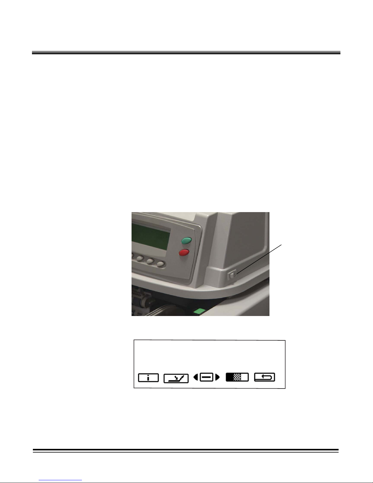
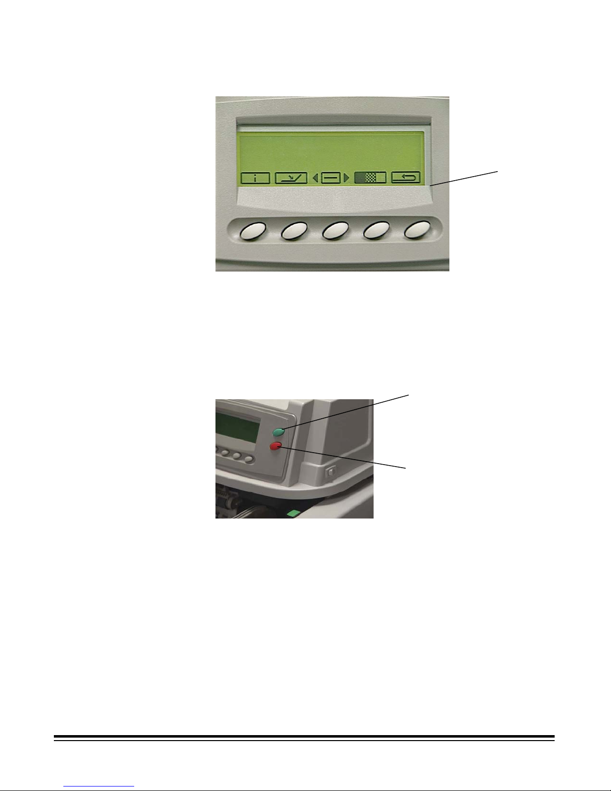
Turning on the scanner
To turn on the scanner:
• Toggle the power switch to the On position.
On/Off switch
When the menu bar is displayed on the Operator Control Panel, the
scanner is Ready.
IMPORTANT: Always power-up the scanner to its Ready state before
A-61169 January 2005 2-1
powering-up the host computer.
Document preparation
Kodak scanners have been tested with a range of documents that
represent the broad spectrum of document types found in the most
common business applications. Optimal scanner performance is
achieved when you scan documents within the recommended document
specifications listed below. Scanning documents that are outside of these
specifications may lead to undesirable results in terms of scanner
reliability, image quality, and/or consumable life.
Before you start scanning, make sure the documents can be fed through
the scanner easily. Best performance is obtained by feeding a good,
clean lead edge. This means the side of the paper which enters the
feeder first should be in the best possible condition.
Use the guidelines below when preparing your documents for scanning.
• Remove staples, rubber bands, loose mending tape or paper clips.
• Straighten wrinkled edges and tape any torn documents.
• Trim ragged edges (steno paper, perforated edges, tractor feed
edges). If ragged edges cannot be trimmed, it is suggested that you
try different feeding orientations to determine which orientation feeds
best.
• A batch of documents to be fed into the scanner must be arranged to
have a common leading edge. Documents may be left-, right-, or
center-aligned in the elevator tray allowing the documents to be fed
into the scanner one at a time.
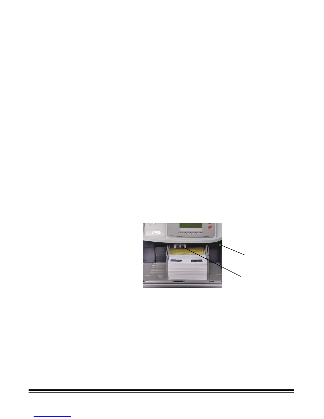
IMPORTANT: Proper alignment of documents is very important.
Documents must be fed under both feed module tires.
Gap release lever
Feed module tires
• Torn, damaged, or crushed pages can be transported successfully
through the scanner. However, no scanner can transport every
possible type of damaged paper. If damaged documents do not feed
through the transport automatically, feed the documents manually.
Use of the gap release lever may be required.
2-2 A-61169 January 2005

• For heavily damaged documents, a clear document protector can be
used with the following limitations:
– Manual feeding is recommended when using a clear document
protector.
– The document in the clear document protector must be fed under
both feed module tires.
– Multi-feed detection must be disabled when manually feeding a
document in a clear document protector.
NOTE: When using a document protector, feed the fold of the
document protector first rather than the open end.
The correct document preparation when using a document protector
is illustrated below:
Small or damaged
Clear
Document
Protector
document
Acceptable document
materials
Recommended paper
weights
Acceptable document
sizes
• Original and recycled papers
• Photographic papers
• Bond (i.e., laser, inkjet, etc.)
• Carbonless paper (some types of carbonless papers contain
chemicals that may react with feed module and separation tires
possibly requiring more frequent tire changes)
• Offset printing papers (i.e., newspapers, magazine pages)
The elevator tray handles a broad range of paper weights, from 50g
(13 lb.) bond paper to 200g (110 lb.) index paper. Heavier documents
may be fed up to 0.76 mm (0.030 in.). Manual feeding mode, using the
gap release lever, may be required to feed heavier paper weights.
• Length:
– Maximum of 76.2 cm (30 in.) with operator-assisted document
feeding and stacking. 43.2 cm (17 in.) is the maximum length for
unattended document feeding.
– Minimum of 6.4 cm (2.5 in.).
• Width:
A-61169 January 2005 2-3
– Maximum of 29.7 cm (11.7 in./image capture – 12 in./transport)
(A3 width)
– Minimum for automatic feeding of 8.9 cm (3.5 in.)
– Minimum for manual feeding of 6.4 cm (2.5 in.)

Maximum document
batch height for
automatic feeding
Downward and upward
curl documents
Adjusting the side
guides on the input
tray
When feeding batched documents, the maximum height of the batched
documents is 10.2 cm (4 in.), approximately 1000 sheets of 75g (20 lb.)
paper. The elevator tray can be set to accommodate 25-, 250- 500-, 7501000-document stacks.
The elevator tray can handle some amount of lead edge curl, but to
ensure reliable feeding the curl should be at a minimum. It is suggested
that you try and minimize the curl before scanning by stacking the
documents on a flat surface for a period of time to help flatten the
documents.
To accommodate multiple applications with variable feeding
requirements, the side guides can be adjusted for center- or edgefeeding. Center-feeding is recommended for best paper handling
performance. The side guides can be moved together or independently.
1. Pull the guides all the way out and then push them together (toward
the center) to reset.
2. Open the side guides slightly wider than the documents you will be
feeding.
3. Place the documents in the elevator tray.
4. Adjust the side guides to fit the documents.
2-4 A-61169 January 2005

Adjusting the output
tray
Different paper types stack differently. The output tray can be set with
either the front or the rear higher for best stacking.
To angle the output tray so the back of the output tray is higher:
1. Lift the output tray up and pull it out of its current slot.
2. Reset it in the slot that matches the desired height.
To angle the output tray so the front of the output tray is higher:
• Lift the front of the output tray up, swing the height adjustment leg out
and insert it into the groove below the output tray.
NOTE: Short side guides are standard on the output tray. However, tall
side guides and self-centering parts are included and can be
changed by you. See Chapter 5, Maintenance for procedures.
A-61169 January 2005 2-5
Scanning documents
Before you scan documents, be sure the menu bar is displayed on the
Operator Control Panel.
Operator Control
panel
Documents must be fed under both feed module tires. For faster
throughput, feed documents into the elevator tray in landscape orientation
(longer side as the leading edge).
To start scanning:
1. Enable the scanner from the host.
2. Place the documents to be fed in the elevator tray.
3. Press Start/Resume.
Start/Resume
Stop/Pause
NOTES:
• Documents must be fed under both feed module tires.
• Do not lean on the elevator tray and/or document extenders while the
scanner is running. If this happens, the elevator tray may make some
noise and stop in position. See the Problem Solving Chart in Chapter
6, Troubleshooting/Messages for procedures on recovery from this
situation.
• Use caution when feeding small documents; small documents may fall
through the slots of the elevator tray and cannot be easily retrieved.
To stop scanning:
• Press Stop/Pause.
2-6 A-61169 January 2005
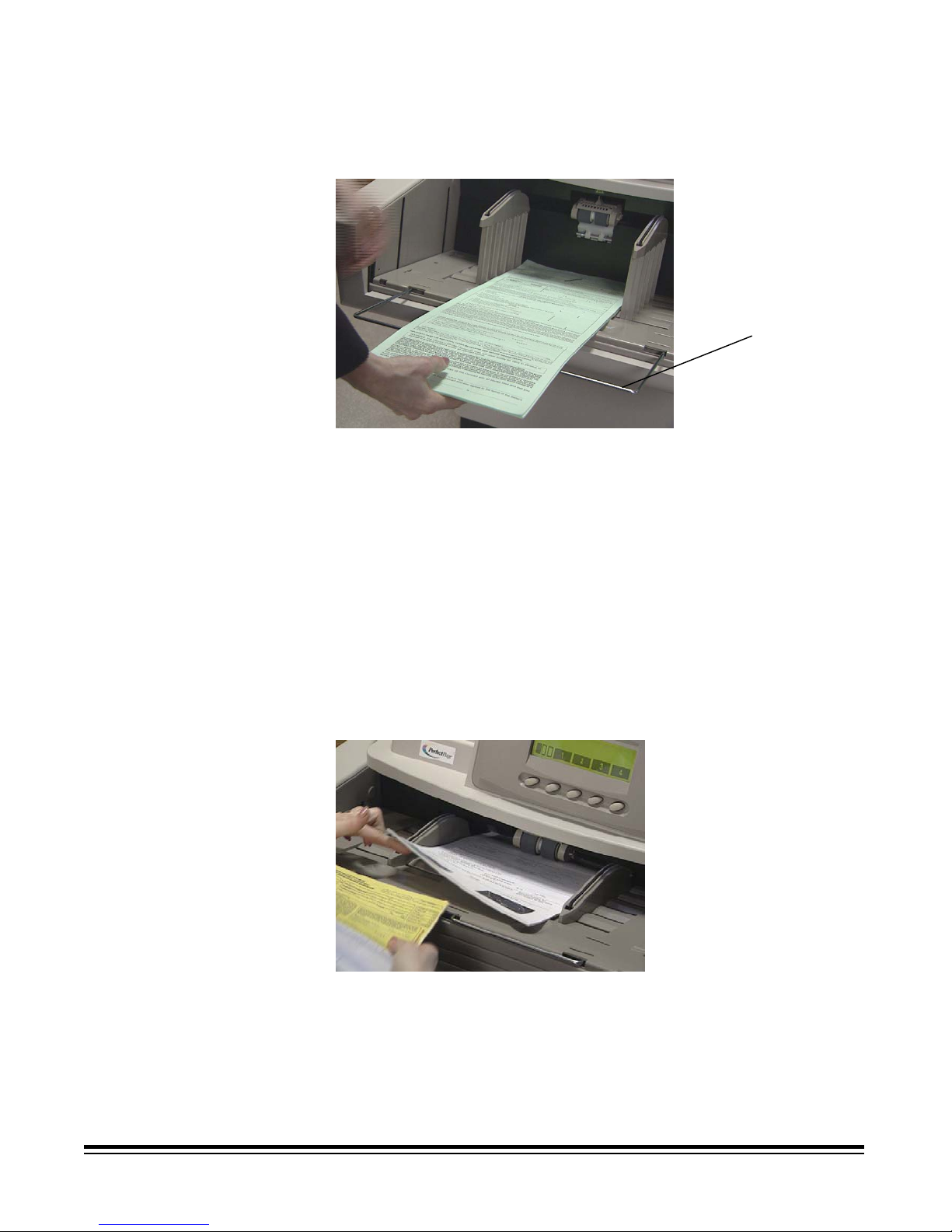
Loading long
documents in the
feeder
Continuous and
manual feeding
The feeder accommodates documents up to 76.2 cm (30 in.) in length. To
feed documents longer than 30.5 cm (12 inches):
1. Pull out the document extenders.
Document
extenders
2. Place the documents in the elevator tray.
NOTE: Operator assistance is required when feeding documents longer
than 43.2 cm (17 in.).
Continuous feeding allows you to place additional batches of documents in
the elevator tray (with operator assistance). Any time during continuous
scanning, additional documents can be added at the bottom of the input
stack. The elevator position must be set to 25 for continuous and manual
feed operations.
To add to a batch of documents:
• Add a small stack of documents to the bottom of the batch in the
elevator tray, by gently lifting the corner of the stack and adding the
documents underneath the last document.
Manual feeding is recommended when you have a heavily damaged
document, envelope or other thick documents, which may require
additional clearance. Follow the guidelines for document size, weight,
quantity, etc. outlined in the section entitled, “Document preparation”
earlier in this chapter.
A-61169 January 2005 2-7

Feeding thick
documents
To feed thick documents:
1. Press and hold the gap release lever this provides more clearance
to ease document feeding.
Gap release lever
2. Push the envelope/thick document into the transport. If more than one
document is to be scanned, feed them into the transport one at a time.
3. After the documents have been fed into the transport, release the gap
release lever.
NOTE: Before feeding envelopes:
− Disable multi-feed detection via the host or programmable
button (if the scanner is set up for multi-feed detection.)
− Be sure the envelope is empty and unsealed.
− When using the gap release lever, the maximum thickness
allowed for a document is 0.76 mm (.030 inches).
2-8 A-61169 January 2005

3 Operator Control Panel Functions
There are a variety of functions available from the Operator Control
Panel. This chapter provides procedures and information for:
• Enabling and disabling the scanner
• Control Panel functions overview
• Navigating through the functions on the Control Panel menu
• Accessing information
• Lowering the elevator tray
• Using the Diagnostics Settings menu
• Performing Diagnostic functions:
− Performing a self-test or extended self-test
− Running in count-only mode
− Performing a print test
− Performing a patch test
• Using the Setting menu:
− Changing the alarm volume
− Changing the display contrast
− Changing the SCSI ID
− Changing the SCSI termination
− Setting the elevator tray position
• Calibrating the scanner
• Jogging the transport
• Programmable key assignments
A-61169 January 2005 3-1
Enabling and disabling
the scanner
Enabling the scanner
The five buttons at the bottom of the Control Panel correspond to the
icons above the buttons To activate the icons, press the corresponding
button.
Icons
Control panel
buttons
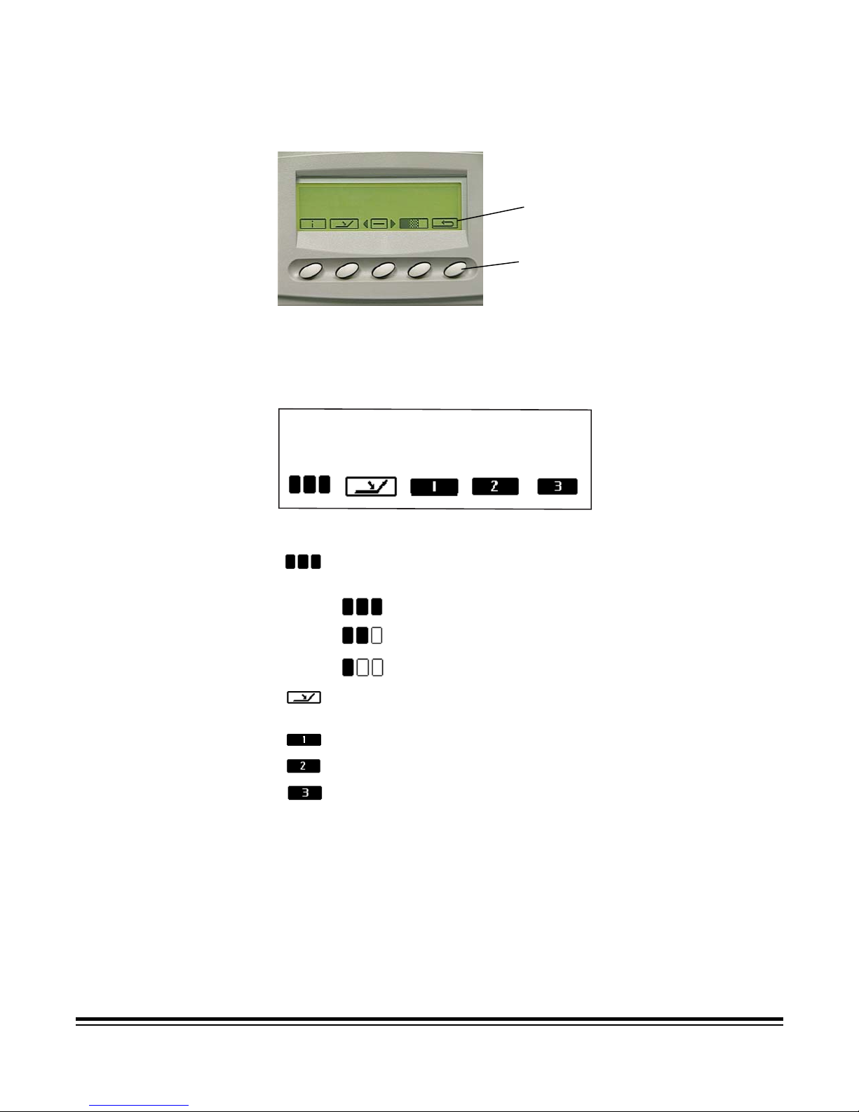
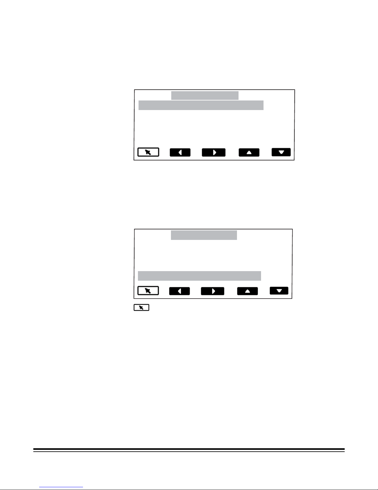
The scanner can only be enabled from the host computer. When the
scanner is enabled, you can change the image address level, override
the elevator setting and use the programmable keys. When enabled, the
icons on the Operator Control Panel will look like this:
These functions can be performed when the scanner is enabled:
Increments the image address level. Depending on the image
address level the icon may appear as follows:
Lowers the elevator tray if it is not already in the lowest
indicating the next image address is level 3
indicating the next image address is level 2
indicating the next image address is level 1
position.
Performs the first programmable function.
Performs the second programmable function.
Performs the third programmable function.
NOTE: Programmable keys are set-up during application setup. Check
with your system administrator for the function of each
programmable key. Possible programmable key assignments
are as follows:
• No scanner functionality (default)
• Scanner End-of-Job
• Terminate Batch
• Omit Multi-feed Detection on Next Document
• Omit Printing on Next Document
• Omit Patch Reading on Next Document
3-2 A-61169 January 2005
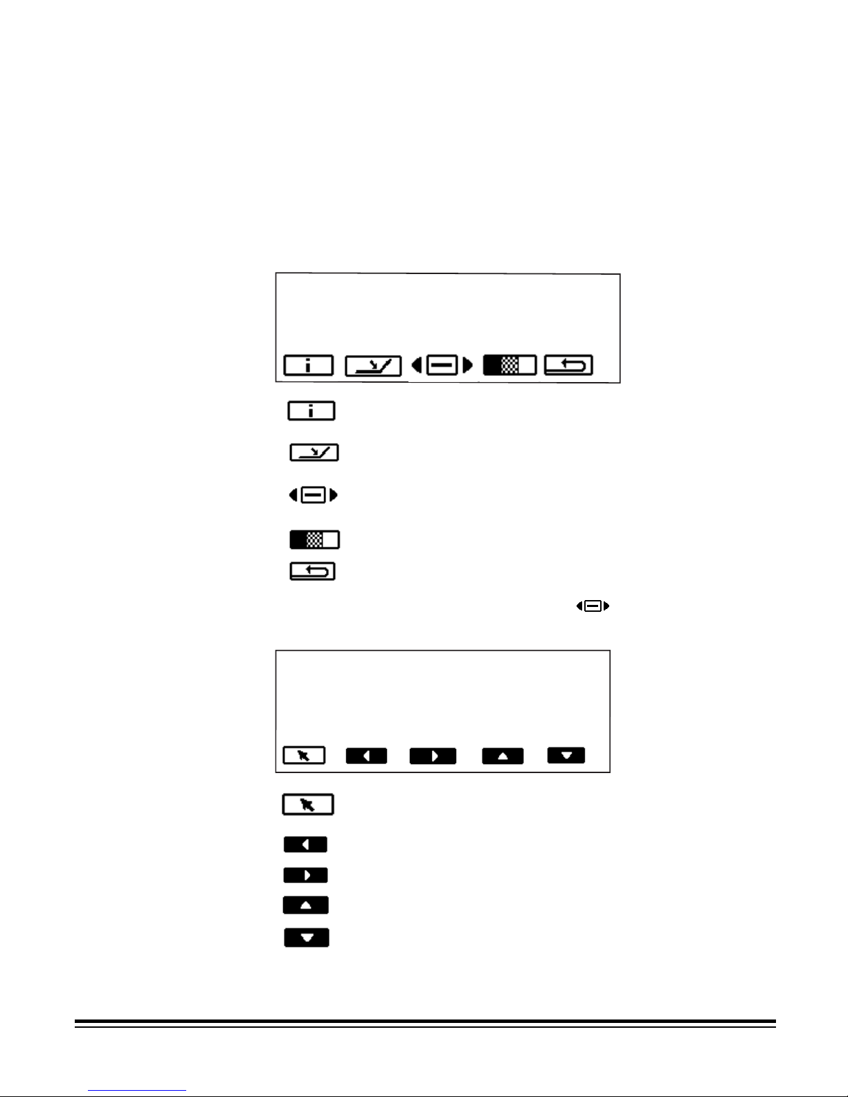
Disabling the scanner
The scanner can be disabled from the host computer or the scanner, if
the end-of-job function is assigned to one of the programmable keys.
When the scanner is disabled, you can display scanner information, lower
the elevator tray, use the Diagnostics Settings menu, calibrate the
scanner and jog the transport.
Disabled scanner functions
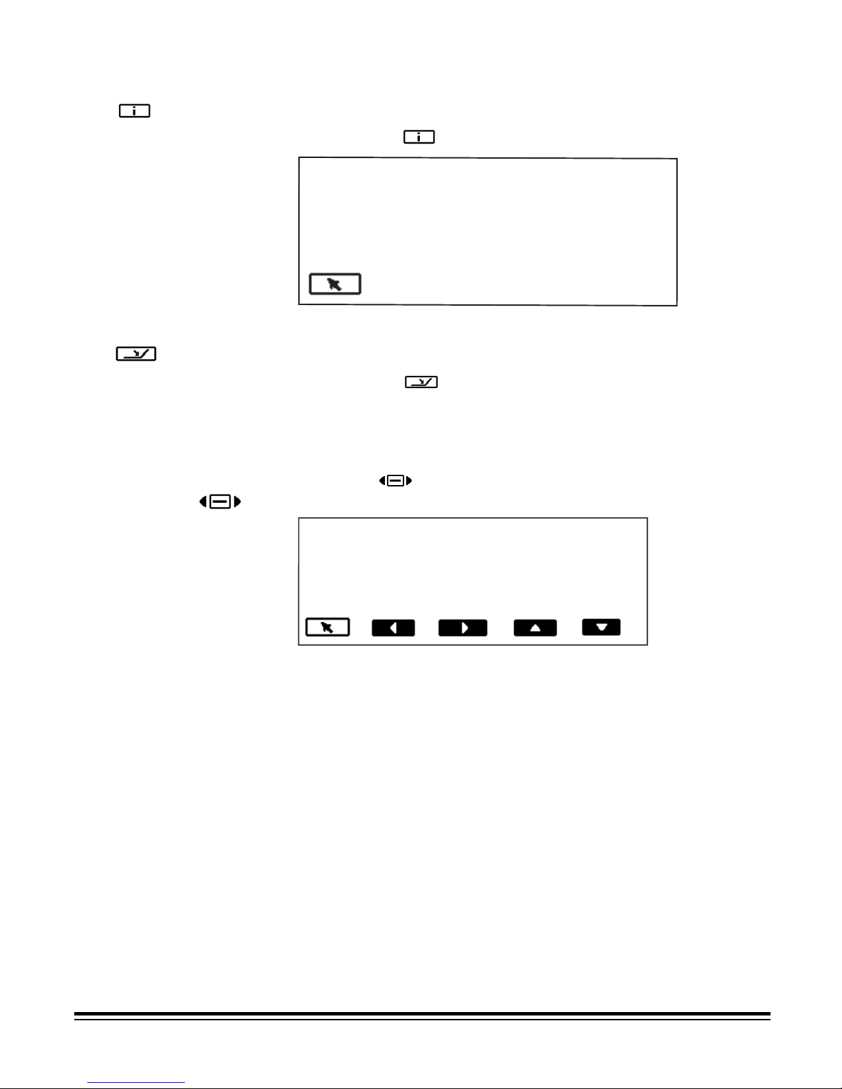
When the scanner is first powered on and disabled, the following icons
will be displayed. These functions can only be performed when the
scanner is disabled.
Displays information: including the last image address,
meter values, scanner serial number.
Lowers the elevator tray if it is not already in the lowest
position.
Displays the Diagnostics Settings menu, which allows
you to perform additional functions.
Calibrates the scanner.
Temporarily turns on the transport to help clear a
document jam.
When the Diagnostics Settings menu button
is selected, these
functions are available:
Exit Diagnostics Settings
Performs the selected function. This button is referred
to as Return.
Moves left to the next selectable item (left arrow).
Moves right to the next selectable item (right arrow).
Moves up to the next selectable item (up arrow).
Moves down to the next selectable item (down arrow).
A-61169 January 2005 3-3
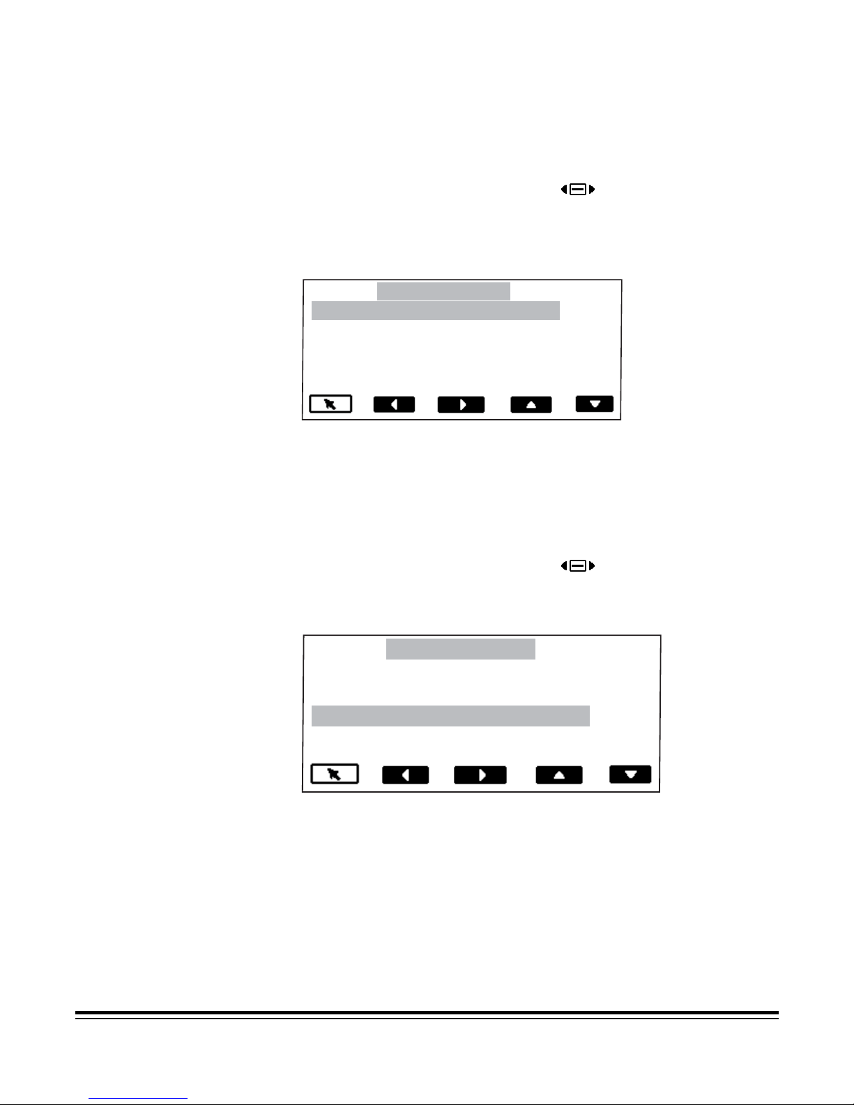
Navigating through the
functions on the
control panel menu
The left and right arrows navigate along the top of the menu bar.
In this example, the left and/or right arrow will rotate through the options
of Exit, Diagnostics and Settings.
Exit Diagnostics Settings
Run self test
Run extended self test
Run count only
Run print test
The up and down arrows navigate through the menu selections.
In this example, the up and/or down arrow will rotate through the options
of Run self test, Run extended self test, Run count only, Run print test,
Run patch test.
NOTE: Only four options can be displayed at a time. Selecting the down
arrow will display additional options.
Exit Diagnostics Settings
Run self test
Run extended self test
Run count only
Run print test
• The Return arrow performs the selected function. In the
example above, after you select Run print test, select the Return
arrow to perform a print test.
3-4 A-61169 January 2005
Accessing information
Lowering the elevator
tray
Using the Diagnostics
Settings menu
The information icon will display information including the last image
address, meter values, and scanner serial number.
• Select this icon
to display information.
0.0.0.1
Pages: 22453
Hours on: 447
Hours feeding: 32
S/N: 76858463
The level of the elevator tray can be set to accommodate various sizes of
document batches.
• Select this icon
NOTE: This will temporarily override the setting, which is configured for
elevator position from the Settings menu. The next time the
scanner is enabled from the host the menu setting will resume.
The Menu icon displays the Diagnostics Settings menu.
to lower the elevator tray to its lowest position.
Exit Diagnostics Settings
The following Diagnostics functions are available:
• Performing a self-test
• Performing an extended self-test
• Running in count-only mode
• Performing a print test
• Performing a patch test
A-61169 January 2005 3-5
Performing a self-test or
extended self-test
Running in count-only
mode
You can perform a self-test or an extended self-test on the scanner. The
self-test is the same test performed when the scanner is powered-up; the
extended self-test is a more thorough test.
To perform a self-test or extended self-test:
1. Select the Diagnostics Settings menu
2. Use the right or left arrow to navigate to the Diagnostics function.
3. Use the down arrow to select Run self-test or Run extended self-
test.
icon.
Exit Diagnostics Settings
Run self-test
Run extended self-test
Run count only
Run print test
4. Select Return. The scanner will run the self-test and report the
results on the display.
You may want to count the number of documents entering the scanner
without actually scanning.
To run in count-only mode:
1. Select the Diagnostics Settings menu
2. Use the right or left arrow to navigate to the Diagnostics function.
3. Use the down arrow to select Run count only.
icon.
Exit Diagnostics Settings
Run self-test
Run extended self-test
Run count only
Run Print test
4. Place the documents in the elevator tray.
5. Select Return. The message Counting Pages will be displayed.
6. Press Start/Resume. The page count will be displayed.
3-6 A-61169 January 2005
 Loading...