

Kodak i800 Series, i810, i820, i830, i840 User Manual

i800 Series Scanners
Image Processing Guide
User’s Guide
A-61510

ISIS is a registered trademark of Pixel Translations, a division of Input
Software, Inc.
Windows and Windows NT are either registered trademarks or
trademarks of Microsoft Corporation in the United States and/or other
countries.
A-61510 January 2005 1-1
1 Introduction
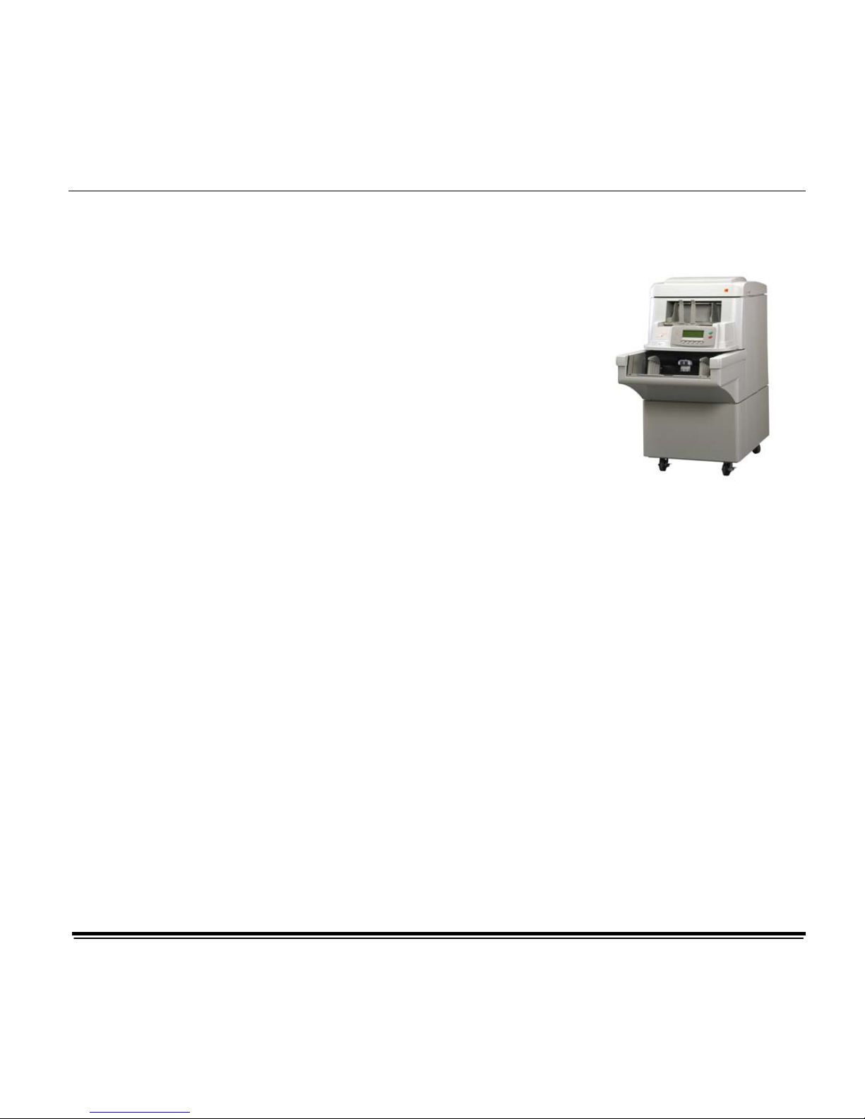
Kodak i800 Series Scanners
The i800 Scanners are high-volume
production scanners which include
image processing technology that
can improve image quality and
sometimes make the reproduction
better than the original.
You can use the ISIS Driver or
TWAIN Data source (both are
available on the CD that is included
with the scanner) or Kodak Digital
Science Capture Software to enable
image processing.
Other popular scanning applications are also compatible with these
scanners, however, these applications may not be able to access all of
the image processing options. Please refer to your application vendor’s
documentation for specific information.
The features
Four configurations of the i800 Series Scanners are available.
♦ Kodak i810 Scanner (bi-tonal) provides bi-tonal scanning with
throughput speeds up to 120 ppm.
♦ Kodak i820 Scanner provides both color/grayscale and bi-tonal
scanning simultaneously with throughput speeds up to 120 ppm.
♦ Kodak i830 Scanner (bi-tonal) provides bi-tonal scanning with
throughput speeds up to 160 ppm.
♦ Kodak i840 Scanner provides both color/grayscale and bi-tonal
scanning simultaneously with throughput speeds up to 160 ppm.

A-61510 January 2005 1-2
About this manual
This manual provides the following:
Chapter 1, Introduction – includes a brief summary of the Kodak i800
Series Scanners, a list of features available for each scanner and the
support drivers.
Chapter 2, Best Practices – includes information to use when setting up
applications, recommendations on how to handle jam recoveries, image
addressing information, controlling print streams, electronic color
drop-out and much more.
Chapter 3, Using the TWAIN Data source – information on using the
dialog boxes presented by the TWAIN Data source and an explanation
of the fields on each tab.
Chapter 4, Using the ISIS Driver – information on using the dialog boxes
presented by the ISIS driver and an explanation of fields on each dialog
box.
Appendix A – provides a list of differences between the traditional
high-volume Kodak scanners vs. the Kodak i800 Series Scanners.
Appendix B – provides information about what type of setups are
allowed and how they can be mixed and matched.
NOTE: The scanned images used in this guide were selected for the
challenges presented to a typical scanner due to the
low-contrast characteristics of the images.
A-61510 January 2005 1-3
Image outputs
i800 Series Scanners can return bi-tonal, grayscale or color images to
the host. Below is a description of the valid combinations.
All i800 Scanners are duplex scanners. This means both the front and
the rear side of each document may be captured. For each side
captured, the scanner creates a bi-tonal/binary only (i810/i830) or a
bi-tonal/binary and color/grayscale (i820/i840) image. The host
application controls which of these images is transferred to the host to
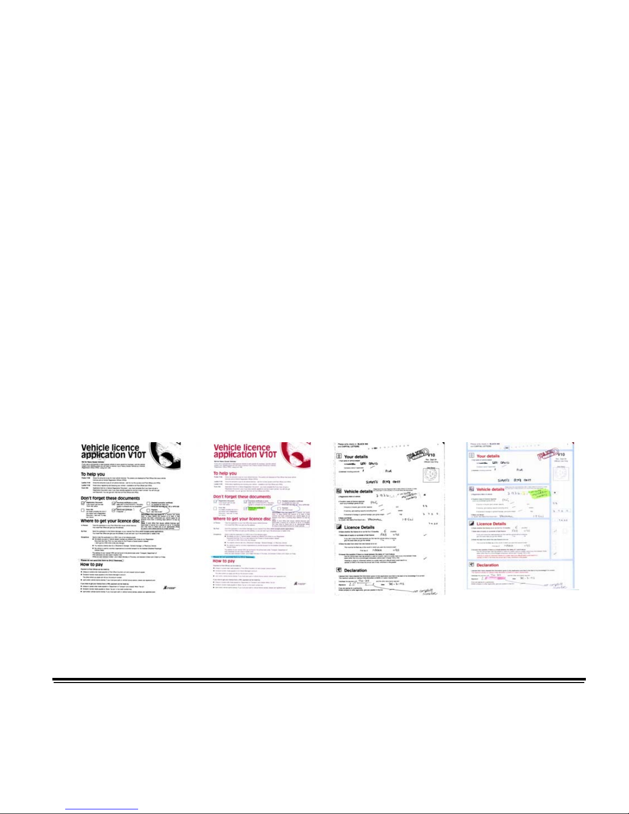
be stored as an image file. For example, for an i840 Scanner if all four
images are returned to the host, the following four files could be created:
• Front bi-tonal/binary: FB.tif. This image file represents the
contents of the front side of the document using one-bit per pixel.
• Front color: FC.jpg. This image file represents the contents of the
front side of the document using 24-bits per pixel.
• Rear bi-tonal/binary: RB.tif. This image file represents the contents
of the rear side of the document using one-bit per pixel.
• Rear color: RC.jpg. This image file represents the contents of the
rear side of the document using 24-bits per pixel.
NOTE: Actual file formats are determined by the host application.
Through the application these image files can be controlled
independently.
FB.tif (front bi-tonal) FC.jpg (front color) RB.tif (rear bi-tonal) RC.jpg (rear color)
A-61510 January 2005 1-4
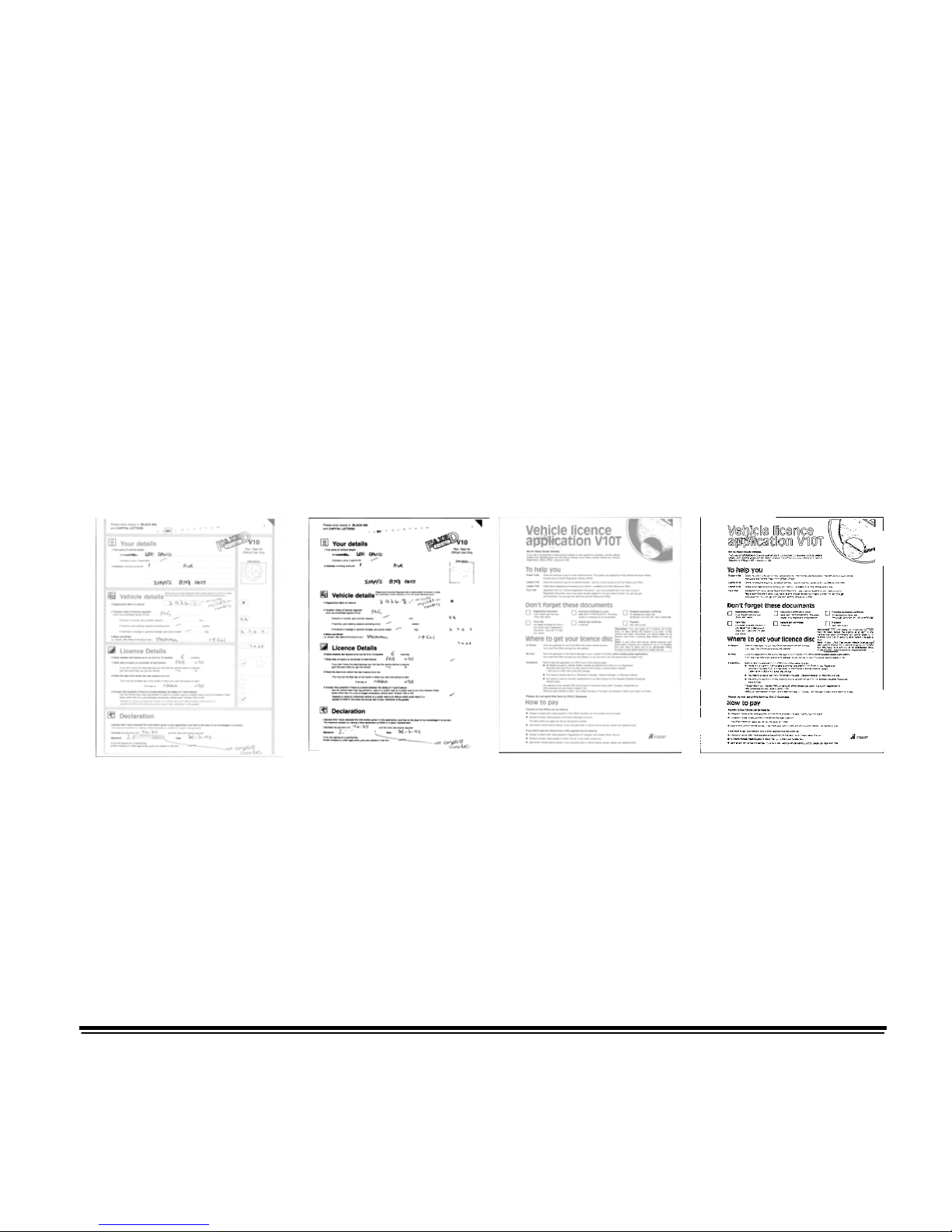
Another example of a simultaneous output where all four images are
returned to the host would create the following four files:
• Front grayscale: FG.jpg. This image file represents the contents of
the front side of the document using 8-bits per pixel.
• Front bi-tonal/binary: FB.tif. This image file represents the
contents of the front side of the document using 1-bit per pixel.
• Rear grayscale: RG.jpg. This image file represents the contents of
the rear side of the document using 8-bits per pixel.
• Rear bi-tonal/binary: RB.tif. This image file represents the contents
of the rear side of the document using 1-bit per pixel.
NOTE: Actual file formats are determined by the host application.
These image files can be controlled through the application
independently.
FG.jpg (front
grayscale)
FB.tif (front
bi-tonal/binary)
RG.jpg (rear
grayscale)
RB.tif (rear
bi-tonal/binary)

A-61510 January 2005 2-1
2 Best Practices
This chapter provides you with recommendations for program
logic, which will allow you to interact efficiently with the i800
Scanner. This high-level information is not intended to be used
as a coding guide. The following information is provided in this
chapter:
• Basic image capture
• Controlling image transfer order – switching between
color/grayscale and bi-tonal
• Jam recovery
• Image file storage locations
• Bar code recognition
• Starting image addresses
• Controlling print strings
• Electronic Color Dropout (form design, drop-out colors)
• Available image header information and its uses
• Zone processing (recombining images, especially for viewing)
• Programmable keys
• Patch reading
• Batching
NOTE: The term host in the sections that follow refers to either the
driver or application depending on code logic.
Basic image capture
Basic image capture is the high-level logic flow for retrieving images
from the scanner.
Follow this sequence to scan documents: set up the scanner,
enable scanning, initiate polling, feed documents and disable
scanning.

A-61510 January 2005 2-2
Scanner setup
To set up the scanner:
1. Set up your scanner operating conditions:
• simplex/duplex
• starting image address
• image order
• lamp timeout
• transport timeout
• transport timeout response
• length detection status and response
• multi-feed detection status and response
• page-on-demand or batch count mode
• starting document count
• batching parameters (batch level, count, start and
end-of-batch functions)
• patch parameters (patch types to recognize, transfer patch
definition)
• printing parameters (printing status, print font, orientation
and strings)
• programmable keys
• level to follow level rules
• confirmation tone
• image address formats
For information on programming these conditions, see Chapters
3 or 4 (depending on your driver). For other vendor tool kits, refer
to their documentation.
2. Select your Color table as appropriate for color document
scanning. See Chapters 3 or 4 (depending on your driver).
For other vendor tool kits, refer to their documentation.

A-61510 January 2005 2-3
3. Determine if any changes to the Image Processing
parameters need to be made for the current application.
NOTE: This check needs to occur for up to four separate images
from the six available options depending on your
application: Front Color, Front Bi-tonal, Front Grayscale,
Rear Color, Rear Bi-tonal, Rear Grayscale.
Image Processing parameter changes remain in effect until
one of the following conditions occur:
• The scanner is powered down using the power switch.
• A SCSI bus device Reset command is executed.
• New imaging parameters are sent from the host.
4. It is recommended that you calibrate the scanner. For
procedures on how to do this, see the Kodak i800 Series
Scanners, User’s Guide.
5. Prepare documents according to the instructions found in the
Kodak i800 Series Scanners, User’s Guide.
Enable scanning
The host must issue a Scan command to enable scanning before
documents can be transported through the scanner. If scanning has
not been enabled, the feeder and transport system will not turn on.
Initiate polling
Initiate host system polling of the scanner to ensure scanned
document images are transferred from the image buffer to the host
system. Polling should continue until scanning is disabled.
For more information see the sections entitled, “Controlling
image transfer order” and “Image header information” later in this
chapter.
Feed documents
Feed documents according to the instructions found in the Kodak
i800 Series Scanners, User's Guide.

A-61510 January 2005 2-4
Disable scanning
Scanning is disabled to allow the host to download configuration/
setup changes between jobs and to handle certain types of errors.
Scanning is also disabled when one of the following conditions
occur:
• The scanner is first powered on using the power switch.
• A SCSI bus device Reset command is executed.
• An End-of-Job indicator is sent by the operator from the operator
control panel.
• A scanner-unique End-of-Job command is issued by the host
computer.
• An error occurs requiring fault recovery.
NOTE: When scanning is disabled, documents cannot be scanned
until the host enables scanning.
Error handling
The scanner recognizes and reports a variety of error conditions.
Some errors are reported to either the host (via the SCSI interface) or
the operator control panel, while others are reported to both the host
and the operator control panel.
An error (via the SCSI interface) is defined as either a current or
deferred error.
A current error results from a problem in processing the current
SCSI command. This can include sending an invalid command,
trying to read from an empty image buffer, or an end-of-job
condition. Since one or more errors may be pending at any time,
current errors are reported first.
A deferred error results from an error condition within the scanner,
such as a document jam. Deferred errors that may have occurred
are reported after current errors.
NOTE: Low level SCSI commands and information will be handled
by your device driver. The following information is provided
for reference only.

A-61510 January 2005 2-5
When an error occurs, the host will receive a SCSI Check
Condition Status. This indicates to the host that there may be one
current error and potentially one or more deferred errors. The
host must follow a Check Condition Status with a SCSI Request
Sense command. The Sense data will indicate the type of error
that has occurred.
To receive subsequent pending errors, the host must execute a
SCSI Test Unit Ready command. If a deferred error is pending,
the Test Unit Ready command will terminate with a Check
Condition Status. The host follows with a SCSI Request Sense
command. The combination of Request Sense followed by Test
Unit Ready must be repeated until a "good" status is returned on
the Test Unit Ready command. A "good" status indicates no
errors (current or deferred) are pending.
IMPORTANT: If at any point the host receives a Check Condition
for a command and fails to issue a subsequent
Request Sense command, the scanner will clear all
(current and deferred) Sense data.
Some error conditions disable scanning and cause the document
transport to stop. These errors are reported on the operator
control panel. This is done to prevent additional images from
entering the image buffer while allowing the host to perform fault
recovery activities.
NOTE: The scanner cannot determine exactly which images were
affected by the error and which images were not.
If an error occurs that disables the scanner, the host can continue
to read images from the image buffer without enabling the
scanner. However, when the image buffer has been emptied, an
error will be generated indicating fault recovery is required. This
differentiates between an end-of-job disable and a disable
caused by an error. The operator may continue scanning
documents after the host enables the scanner.

A-61510 January 2005 2-6
Controlling image
transfer order
This section provides job stream examples which can be used in
scanning applications.
The host application is responsible for determining the order in
which the scanner returns images. Front images must always be
retrieved before rear images.
Bi-tonal only duplex
This job stream is available for all i800 Series Scanners.
1. Prepare documents.
2. Start the scanner to do bi-tonal duplex scanning (front bi-tonal
and rear bi-tonal).
3. Setup the scanner to retrieve bi-tonal images.
4. Enable the scanner and start polling.
Loop
Read front bi-tonal image header
Read bi-tonal image
Read rear bi-tonal image header
Read bi-tonal image
End loop
Color only duplex
This job stream is available for i820 and i840 Series Scanners.
1. Prepare documents.
2. Start the scanner to do color duplex scanning (front color and
rear color).
3. Setup the scanner to retrieve color images.
4. Enable the scanner and start polling.
Loop
Read front color image header
Read color image
Read rear color image header
Read color image
End loop

A-61510 January 2005 2-7
Grayscale only duplex
This job stream is available for i820 and i840 Series Scanners.
1. Prepare documents.
2. Start the scanner to do grayscale duplex scanning (front
grayscale and rear grayscale).
3. Setup the scanner to retrieve grayscale images.
4. Enable the scanner and start polling.
Loop
Read front grayscale image header
Read grayscale image
Read rear grayscale image header
Read grayscale image
End loop
Dual stream simplex
This job stream is available for i820 and i840 Series Scanners.
1. Prepare documents.
2. Start the scanner to do dual stream simplex scanning (front
bi-tonal and front color).
3. Setup the scanner to retrieve bi-tonal images first.
4. Enable the scanner and start polling.
Loop
Read front bi-tonal image header
Read bi-tonal image
Read front color image header
Read color image
End loop

A-61510 January 2005 2-8
Dual stream duplex
This job stream is available for i820 and i840 Series Scanners.
1. Prepare documents.
2. Start the scanner to do dual stream duplex scanning (front
bi-tonal, front color, rear bi-tonal and rear color).
3. Setup the scanner to retrieve bi-tonal images first.
4. Enable the scanner and start polling.
Loop
Read front bi-tonal image header
Read bi-tonal image
Read front color image header
Read color image
Read rear bi-tonal image header
Read bi-tonal image
Read rear color image header
Read color image
End loop

A-61510 January 2005 2-9
Single-stream duplex
alternating between bi-tonal
and color/grayscale using
the scanner Toggle patch
This job stream is available for i820 and I840 Series Scanners.
The Toggle patch is a type 4 patch that is used to trigger the scanner
to switch from the current image stream (bi-tonal) to the alternative
image stream (color/grayscale).
The example illustrates using patch type 4 in the same way
which the “color patch” is utilized on the Kodak Digital Science
Scanner 3590C where it starts using bi-tonal.
1. Prepare documents with a patch Type 4 before and after any
color/grayscale documents.
2. Configure image processing parameters for all four images.
Before initiating the scanner, select only the front and rear
bi-tonal images to be retrieved.
3. Select both sides from the Toggle Patch drop-down box.
4. Start scanning.
Images will begin in bi-tonal and will change to color/grayscale
when the first toggle patch is detected. Images will remain
color/grayscale until the next toggle patch is detected. Images of
the toggle patch sheet will not be returned to the host unless you
also enable patch reading and select the Type 4 patch.

A-61510 January 2005 2-10
Jam and Fault recovery
This section provides recommendations for application logic
associated with scanner jam and fault recovery.
If your scanner is enabled and you are polling when a document jam
or other fault occurs, use the following procedure to restart
scanning.
IMPORTANT: Before beginning fault recovery, make sure all the
headers and images have been transferred from the
image buffer to the host system.
When a document jam or other fault occurs, the feeder and the
transport will stop and the scanner will be disabled.
1. When all images have been retrieved from the scanner
(image buffer empty), display the last image retrieved for
operator viewing.
2. Use the image header of the last image retrieved to
determine the image address and sequential counter.
3. Use the information above +1 to seed the next image
address and sequential counter before re-enabling the
scanner.
4. Instruct the operator to sort through the stack of documents
being scanned to find the document that produced the last
successfully scanned image. They must rescan all of the
documents that follow the last successfully scanned
document.
5. Enable the scanner.

A-61510 January 2005 2-11
Image file storage
locations
This section provides general recommendations regarding the impact
of image file storage locations on the overall throughput of the scanner.
Depending upon the model of your scanner, you can receive up
to four image files per document. Decisions about where to write
these files when retrieving them from the scanner could impact
the overall throughput of the scanner. In order to prevent
overwriting data the scanner stops feeding paper when the
internal image buffer reaches two-thirds capacity. Scanning will
not resume until buffer memory reaches one-third. In order to
minimize the number of times this condition might occur, it is
recommended that image files are written to a local hard drive in
order to avoid the potential overhead of transferring files across
the network to remote drives during scanning.
Bar code recognition
This section provides general information about bar code recognition
and read rates.
Unlike previous high-volume scanners from Kodak, the i800
Series Scanners do not include a bar code accessory. Bar code
functionality is now the responsibility of the host system. The
main imaging parameter, which may affect bar code read rates, is
resolution. Depending upon your scanner model, either bi-tonal,
grayscale or color images may be used for bar code applications.
Refer to your software documentation for their recommendations
and/or requirements for image file quality to achieve desired read
rates.

A-61510 January 2005 2-12
Image addressing
Unlike previous high-volume scanners from Kodak, the i800 Series
Scanners moved all image address functionality to the host. This
includes index format, starting image address, image address format
and level rules.
Image address format
The image address format can be from one to four fields. Each field
may be up to 9 characters. Total image address length with delimiters
is 30 characters. Each field may use level 1, level 2, level 3, and fixed
fields, and must be explicitly defined by the application. Image address
format is flexible and includes the ability to define four fixed fields. See
Chapter 3 or 4 (depending on your driver) for more information.
The order of importance for the fields (from highest to lowest) is
fixed, level 3, level 2, level 1. When defining an image address,
the field with the highest importance must always be to the left.
For example, F321 is a valid format. F123 is not a valid format.
You are not required to use all four fields. If you chose to use
fewer than four fields, you must specify a field width of 0 for any
unused field. 0 width fields may not be between two non-zero
width fields.
When defining fields, you can only have one field assigned to
each individual level. For example, FF21 is a valid format. FF11
is not a valid format.
When defining more than one fixed field the fixed field values
must be to the left of any index value. Fixed fields may not be
between level fields. For example, FFF1 is a valid format. FF1F
is not a valid format.
Starting image address/
next image address
The host application must always seed the scanner with the starting
image address. It is no longer controlled within the scanner. The
scanner will return the image address associated with each image in
the image header. The application can track this image address for use
in setting the next image address when restarting the scanner.

A-61510 January 2005 2-13
Indexing schemes
Documents are scanned to record the information in an easily
accessible form. The scanner offers the following indexing schemes:
• Single level
• Two level
• Two level offset
• Three level
• Three level offset
Single level indexing
When using single level indexing, the image address assigned to
each document is defined as follows:
• Field D is defined as a Level 1 field having a field length greater
than 0.
• Fields C, B and A may be defined as fixed fields if desired.
For example, if you scan a book with 50 pages and do not want a
fixed field in the image address, the image address is defined as
follows:
• Field D has a field length of 2 characters and is defined as a
Level 1 field.
• Fields A, B and C have 0 characters.
Image Address 01
Image Address 02
Image Address 03
Image Address 05
0
Page 50
…
Page 3
Page 2
Page 1
The first page is assigned image address 01. The second page is
assigned image address 02, and so on, through the remainder of
the book.
Any one of the 50 pages may later be located and retrieved using
its unique image address.

A-61510 January 2005 2-14
Two level indexing
When using two level indexing, the image address assigned to
each document is defined as follows:
• Field D (Level 1) defined as having a field length greater than 0.
• Field C (Level 2) defined as having a field length greater than 0.
• Fields B and A may be defined as fixed fields if desired.
For example, if you scan a book with 2 chapters (Chapter 1 has
40 pages and Chapter 2 has 60 pages) the image address has
been defined:
• Field D has 3 characters
• Field C has 2 characters
• Field B has 0 characters
• Field A has 0 characters
Chapter 1
Header
Page 1-1
Page 1-2
Page…
Page 1-40
Chapter 2
Header
Page 2-1
Page 2-2
Pa
g
e…
Page 2-60
Image Address 01.000
Image Address 01.001
Image Address 01.002
Image Address 01.040
Image Address 02.000
Image Address 02.001
Image Address 02.002
Image Address 02.060
The header page for Chapter 1 is assigned image address
01.000. The first page of Chapter 1 is assigned image address
01.001; the second page is assigned image address 01.002, and
so on through Chapter 1.
The header page for Chapter 2 is assigned image address
02.000. The first page of Chapter 2 is assigned image address
02.001; the second page is assigned image address 02.002, and
so on through Chapter 2.
Any one of the pages may later be located and retrieved using its
unique image address.

A-61510 January 2005 2-15
Two level offset indexing
When using two level offset indexing, the image address
assigned to each document is defined as follows:
• Field D (Level 2) defined as having a field length greater than 0.
• Fields C, B and A may be defined as fixed fields if desired.
For example, if you scan a book with 2 chapters (Chapter 1 has
40 pages and Chapter 2 has 60 pages), the image address has
been defined:
• Field D has 2 characters
• Field C has 0 characters
• Field B has 0 characters
• Field D has 0 characters
Chapter 1
Header
Page 1-1
Page 1-2
Page…
Page 1-40
Chapter 2
Header
Page 2-1
Page 2-2
Pa
g
e…
Page 2-60
Image Address 01
Image Address 01
Image Address 01
Image Address 01
Image Address 02
Image Address 02
Image Address 02
Image Address 02
The header page for Chapter 1 is assigned image address 01.
The remaining pages of Chapter 1 are also assigned image
address 01.
The header page for Chapter 2 is assigned image address 02.
The remaining pages of Chapter 2 are also assigned image
address 02.
Either one of the chapter header pages may later be located and
retrieved using its unique image address. Pages within a chapter
may be located and retrieved by first finding the chapter header
and then manually scrolling through the remaining pages of the
chapter.

A-61510 January 2005 2-16
Three level indexing
When using three level indexing, the image address assigned to
each document is defined as follows:
• Field D (Level 1) defined as having a field length greater than 0.
• Field C (Level 2) defined as having a field length greater than 0.
• Field B (Level 3) defined as having a field length greater than 0.
• Field A may be defined as fixed field if desired.
For example, if you scan a book with two sections (Section 1
contains 2 chapters, each having 40 pages; Section 2 contains
only 1 chapter, having 120 pages) the image address has been
defined:
• Field D has 3 characters
• Field C has 2 characters
• Field B has 1 character
• Fixed field has 0 characters
Section1
Header
Chapter 1
Header
Page 1-1
Page…
Page 1-40
Chapter 2
Header
Page 2-1
Pa
g
e…
Page 2-40
Image Address 1.00.000
Image Address 1.01.000
Image Address 1.01.001
Image Address 1.01.040
Image Address 1.02.000
Image Address 1.02. 001
Image Address 1.02.040
Section 2
Header
Chapter 1
Header
Page 1-1
Page…
Page 1-120
Image Address 2.00.000
Image Address 2. 01.000
Image Address 2.01.0 01
Image Address 2.01.1 20
The header page for Section 1 is assigned image address
1.00.000. The header page for Chapter 1 of the section is
assigned image address 1.01.000. The pages within the Chapter
are assigned image address(es) 1.01.001 through 1.01.040. The
header page for Chapter 2 of the section is assigned image
address 1.02.000. The pages within the chapter are assigned
image address(es) 1.02.001 through 1.02.040.

A-61510 January 2005 2-17
The header page for Section 2 is assigned image address
2.00.000. The header page for Chapter 1 of the section is
assigned image address 2.01.000. The pages within the chapter
are assigned image address(es) 2.01.001 through 2.01.120.
Any one of the pages may later be located and retrieved using its
unique image address.

A-61510 January 2005 2-18
Three level offset indexing
When using three level offset indexing, the image address
assigned to each document is defined as follows:
• Field D (Level 2) defined as having a field length greater than 0.
• Field C (Level 3) defined as having a field length greater than 0.
• Fields B and A may be defined as fixed fields if desired.
For example, if you scan a book with two sections (Section 1
contains 2 chapters, each having 40 pages; Section 2 contains
only 1 chapter, having 120 pages) the image address has been
defined:
• Field D has 2 characters
• Field C has 1 characters
• Field B has 0 character
• Field A has 0 characters
Section1
Header
Chapter 1
Header
Page 1-1
Page…
Page 1-40
Chapter 2
Header
Page 2-1
Page…
Page 2-40
Image Address 1.00
Image Address 1.01
Image Address 1.01
Image Address 1.01
Image Address 1.02
Image Address 1.02
Image Address 1.02
Section 2
Header
Chapter 1
Header
Page 1-1
Page…
Page 1-120
Image Address 2.00
Image Address 2.01
Image Address 2.01
Image Address 2.01
The header page for Section 1 is assigned image address 1.00.
The header page for Chapter 1 of the section is assigned image
address 1.01. The remaining pages of Chapter 1 are also
assigned image address 1.01. The header page for Chapter 2 of
the section is assigned image address 1.02. The remaining
pages of Chapter 2 are also assigned image address 1.02.

A-61510 January 2005 2-19
The header page for Section 2 is assigned image address 2.00.
The header page for Chapter 1 of the section is assigned image
address 2.01. The remaining pages of Chapter 1 are also
assigned image address 2.01.
Either one of the section header or chapter header pages may
later be located and retrieved using its unique image address.
Pages within a chapter may later be located and retrieved by first
finding the chapter header and then manually scrolling through
the remaining pages of the chapter.
Controlling document level changes
The previous Indexing Scheme examples have illustrated how
document levels change within a single group of documents.
There are four document image levels: 3, 2, 1, and 0.
There are a number of ways in which you can set or change the
document level:
• You can change image address level via the Level icon
on
the Operator Control Panel. Selecting the Level icon increments
the image address level to Level 1, Level 2 or Level 3.
• You can send a new image address from the host PC.
• You may use the Patch Reader; feeding a document containing a
particular type of patch can change document levels.
• Starting a new batch can cause the image address level to
change depending on the application.
If you do not set or change the document level using one of the
methods listed, the document level will be set automatically
based upon the level rules (i.e., Level 2 is followed by Level 1,
etc.) defined during scanner setup.
A-61510 January 2005 2-20
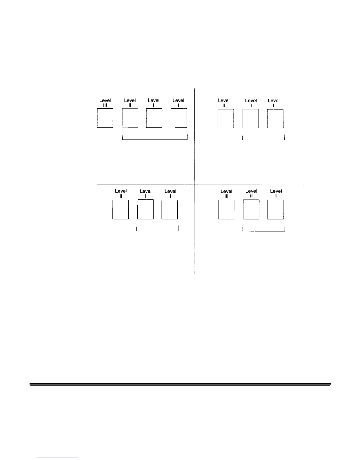
The following diagram illustrates how document levels are set or
changed:
Generated Automatically
Generated Automatically
Generated Automatically
Generated Automatically
Document level information is transmitted in each image header.
Level Instruction:
Operator selects Level II using the Level icon on
the OCP or uses a patch II document (Level 1
documents are generated automatically using the
level to follow level rules).
Level Instruction:
Operator selects Level III using the Level icon on the
OCP a (Level II and I documents are generated
automatically using the level to follow level rules).
Level instruction:
Operator selects Level III using the Level icon on the
OCP or uses a patch III document (Level II and I
documents are generated automatically using the
level to follow level rules).
Level Instruction:
Operator selects Level II using the Level icon on the
OCP (Level I documents are generated automatically
using the level to follow level rules).
1
2
3
4
1
2
3
1 2 3 1
2
3

A-61510 January 2005 2-21
Level rules
Unlike previous high-volume scanners from Kodak, the i800 Series
Scanners moved the responsibility for defining and controlling level
rules to the host. Level rules are an automated way to control
document image addressing based on the level of the previous
document. The application must define the Level to Follow Level
scheme. For example:
For a 3 level indexing scheme the application must define the
Level to Follow Level rules for level 3, level 2, and level 1.
Level Level to Follow
Level
3 2
2 1
1 1
Level to follow level rules are used to automatically drop to a
lower level. Returning to a higher level is generally done through
patch or application control of the next image address.

A-61510 January 2005 2-22
Controlling print
strings
Full control and access to the scanner’s print string functionality is
available from the host application. In addition the print string
information is returned to the host in the image header.
Print String formatting
• Maximum character length 40.
• Character set full alphanumeric, including special characters.
NOTE: To view Japanese characters correctly you must get the
MS Gothic font set by installing the Microsoft Global IME
5.01 for Japanese – with Language Pack, English
Language Version which can be found at
http://www.microsoft.com/ms
download/iebuild/ime5_win32/en/ime5_win32htm.
• Distance from lead edge a minimum of a ¼-inch.
• Can print to within ½-inch of the trial edge.
Electronic color
dropout
The i800 Series Scanners provide the ability to create dropout images
without changing lamps. The application has the ability to select red,
green and blue dropout functionality. Only one color can be dropped
out at a time. This dropout performance is equivalent to color dropout
functionality when using the traditional color lamp technique.
Electronic color dropout is used with OCR and ICR applications.
See your vendor’s documentation for recommendations on
image quality characteristics.
Electronic color dropout is applied to bi-tonal image chain only.
There are four imaging parameters, which effect electronic color
dropout: Threshold Value/Filter Threshold, Background
Value/Background, Contrast %, and Threshold.
The tables that follow provide Pantone colors that may be used
with the red, green and blue dropout option.

A-61510 January 2005 2-23
Two categories of performance are provided or each color:
Colors that can be completely dropped out and colors that are
very close to complete dropout. These values were established
by using standard Pantone
Matching System® Colors guide
(uncoated, 175-line screen). If the background of the document
you are using is not bright white the results may vary. The default
settings are:
Contrast% = 50
Threshold = 90
Color Filter = 175
Background = 245 this value should be set to match
background color of your document.
Resolution = 200 dpi
If the values above do not give you the desired results, you may
need to vary these values accordingly.

A-61510 January 2005 2-24
Red dropout
Following is a list of Pantone
colors which may be used with the red
dropout option.
Red Dropout Complete Dropout
100 U 114 U 1225 U 1365 U 169 U 210 U 2562 U 395 U
101 U 115 U 1235 U 141 U 176 U 217 U 372 U 3935 U
102 U 116 U 127 U 148 U 1765 U 223 U 379 U 3945 U
Yellow U 120 U 128 U 149 U 1767 U 230 U 380 U 3955 U
106 U 121 U 129 U 150 U 182 U 236 U 386 U 3965 U
107 U 122 U 134 U 1485 U 189 U 2365 U 387 U
108 U 123 U 135 U 155 U 1895 U 243 U 388 U
109 U 1205 U 1345 U 1555 U 196 U 250 U 393 U
113 U 1215 U 1355 U 162 U 203 U 256 U 394 U
Red Dropout Near Complete Dropout
130 U 1505 U 165 U 177 U 184 U 199 U 225U 2395 U
136 U
Orange
021 U
166 U 178 U 185 U 204 U
Rubine
Red U
Rhodamine
Red U
137 U 156 U 1625 U 179 U 190 U 205 U 226 U 244 U
138 U 157 U 1635 U 1775 U 191 U 206 U 231 U 245 U
1375 U 158 U 1645 U 1785 U 192 U 211 U 232 U 246 U
142 U 1565 U 1655 U 1788 U 1905 U 212 U 237 U 251 U
143 U 1575 U 1665 U 1777 U 1915 U 213 U 238 U 252 U
144 U 1585 U 170 U 1787 U 1925 U 218 U 239 U 257 U
151 U 163 U 171 U Red 032 U 197 U 219 U 2375 U 365 U
1495 U 164 U 172 U 183 U 198 U 224 U 2385 U 396U
Green Dropout Complete Dropout
100 U 109 U 1215 U 318 U 352 U 375 U 388 U 3945 U
101 U 113 U 127 U 324 U 358 U 379 U 389 U 3955 U
102 U 114 U 134 U 3245 U 365 U 380 U 393 U 3965 U
Yellow U 115 U 135 U 331 U 366 U 381 U 394 U
106 U 120 U 1345 U 332 U 372 U 382 U 395 U
107 U 121 U 148 U 3375 U 373 U 386 U 396 U
108 U 1205 U 317 U 351 U 374 U 387 U 3935 U
 Loading...