

Kodak i5x50 User Manual


3rd Party Licenses
This software is based in part on the work of the Independent JPEG Group
Copyright (C)2009-2013 D. R. Commander. All Rights Reserved.
Redistribution and use in source and binary forms, with or without modification, are permitted provided that the
following conditions are met:
- Redistributions of source code must retain the above copyright notice, this list of conditions and the following
disclaimer.
- Redistributions in binary form must reproduce the above copyright notice, this list of conditions and the
following disclaimer in the documentation and/or other materials provided with the distribution.
- Neither the name of the libjpeg-turbo Project nor the names of its contributors may be use d to endorse or
promote products derived from this software without specific prior written permission.
THIS SOFTWARE IS PROVIDED BY THE COPYRIGHT HOLDERS AND CONTRIBUTORS "AS IS", AND ANY
EXPRESS OR IMPLIED WARRANTIES, INCLUDING, BUT NOT LIMITED TO, THE IMPLIED WARRANTIES OF
MERCHANT ABILITY AND FITNESS FOR A PARTICULAR PURPOSE ARE DISCLAIMED. IN NO EVENT SHALL
THE COPYRIGHT HOLDERS OR CONTRIBUTORS BE LIABLE FOR ANY DIRECT, INDIRECT, INCIDENTAL,
SPECIAL, EXEMPLARY, OR CONSEQUENTIAL DAMAGES (INCLUDING, BUT NOT LIMITED TO,
PROCUREMENT OF SUBSTITUTE GOODS OR SERVICES; LOSS OF USE, DATA, OR PROFITS; OR
BUSINESS INTERRUPTION) HOWEVER CAUSED AND ON ANY THEORY OF LIABILITY, WHETHER IN
CONTRACT, STRICT LIABILITY, OR TORT (INCLUDING NEGLIGENCE OR OTHERWISE) ARISING IN ANY
WAY OUT OF THE USE OF THIS SOFTWARE, EVEN IF ADVISED OF THE POSSIBILITY OF SUCH DAMAGE.

OVERVIEW 1-1
INSTALLATION 2-1
SCANNING 3-1
DOCUMENT PRINTING 4-1
DUAL CONTROLLED STACKING 5-1
PATCH READING 6-1
MAINTENANCE 7-1
TROUBLESHOOTING 8-1
APPENDICES
Specifications
Warranty
A & B

Safety
User Precautions
• Place the desktop scanner on a sturdy, level work surface capable of supporting 57.6 kg (127 lbs) and leave adequate
clearance on all sides of the scanner.
• When relocating the desktop scanner, it is recommended that at least two people lift the scanner and use safe lifting
techniques.
• Do not install the scanner in a location subject to dust, humidity or steam. This may cause electrical shock or a fire. Only use
the scanner indoors in a dry location.
• Make sure the electrical power outlet is located within 1.52 meters (5 feet) of the scanner and is easily accessible.
• When disconnecting equipment from the electric socket, be sure to grasp the plug, not the cord.
• Be sure the power cord is securely plugged into the wall outlet.
• Do not damage, knot, cut or modify the power cord or use a damaged power cord.
• The scanner requires a dedicated and properly grounded power outlet. Do not use an extension cord or power strip with the
scanner.
• Leave sufficient space around the power outlet so it can be easily unplugged in case of an emergency.
• Do not use the scanner if it becomes inordinately hot, has a strange odor, emits smoke, or makes unfamiliar noises.
Immediately stop the scanner and disconnect the power cord from the power outlet. Contact Service.
• Do not disassemble, service or modify the scanner except as explained in the User’s Guide.
• Do not move the scanner with the power cord and interface cable attached. This may cause damage to the cord/cable.
Remove the power cord from the wall outlet before moving or relocating the sca nner.
• Follow the Kodak Alaris recommended cleaning procedures. Do not use air, liquid or gas spray cleaners. These cleaners
displace dust, dirt and debris to other locations within the scanner, which may cause the scanner to malfunction.
• Material Safety Data Sheets (MSDS) for chemical products are available on the Kodak Alaris website at:
www.kodakalaris.com/en-us/about/ehs. When accessing the MSDSs from the website, you will be required to provide the
catalog number or keyword of the consumable you want the Material Safety Data Sheet for. See the section entitled,
“Supplies and consumables” later in this guide for supplies and catalog numbers.
• This device is not intended for use in the direct field of view at visual display workplaces. To avoid incommoding reflexions at
visual display workplaces, this device must not be placed in the direct field of view.
• Users and their employers need to observe the common sense precautions applicable to the operation of any machinery.
These include, but are not limited to, the following:
• Do not wear loose clothing, unbuttoned sleeves, etc.
• Do not wear loose jewelry, bracelets, bulky rings, long necklaces, etc.
• Hair length should be kept short, using a hair net if needed, or tying long hair up in a bundle.
• Remove all other loose objects from the area that could be drawn into the machine.
• Take sufficient breaks to maintain mental alertness.
• Use only the recommended cleaning supplies.
• Do not use canned/compressed air.
Supervisors should review their employee practices and make compliance with these precautions a part of the job description
for operation of the scanner or any mechanical device.
Warning labels
CAUTION: Moving parts, avoid contact.
CAUTION: Hot surface, avoid contact.
Environmental information
•The Kodak i5x50 Series Scanners are designed to meet worldwide environmental requirements.
• Guidelines are available for the disposal of consumable items that are replaced during maintenance or service; follow local
regulations or contact Kodak Alaris locally for more information.
• For recycling or reuse information, contact your local authorities, or in the USA, go to:
www.kodakalaris.com/go/scannerrecycling.
• The product packaging is recyclable.
• Kodak i5x50 Scanners are Energy Star compliant and shipped from the factory with the default time set to 15 minutes.
Battery Information
This product contains a battery that is not user-serviceable. This battery can only be removed or replaced by a
qualified Service Engineer.
European Union
This symbol indicates that when the last user wishes to discard this product, it must be sent to appropriate
facilities for recovery and recycling. Please contact your local Kodak Alaris representative or refer to
www.kodakalaris.com/go/recycle for additional information on the collection and recovery programs available for
this product.
Please consult http://www.kodakalaris.com/en-us/about/ehs/product-declarations for information about the
presence of substances included on the candidate list according to article 59(1) of Regulation (EC) No. 1907/2006 (REACH).
Acoustic emission
Maschinenlärminformationsverordnung – 3, GSGV
Der arbeitsplatzbezogene Emissionswert beträgt <70 dB(A).
[Machine Noise Information Ordinance — 3, GSGV
The operator-position noise emission value is <70 dB(A).]
EMC statements - for Kodak i5250/i5650/i5250V/i5650VScanners
United States: This equipment has been tested and found to comply with the limits for a Class B digital device pursuant to Part
15 of the FCC rules. These limits are designed to provide reasonable protection against harmful interference in a residential
installation. This equipment generates, uses, and can radiate radio frequency energy and, if not installed and used in
accordance with the instruction manual, may cause harmful interference to radio communications. However, there is no
guarantee that interference will not occur in a particular installation. If this equipment does cause harmful interference to radio or
television reception, which can be determined by turning the equipment off and on, the user is encouraged to try to correct the
interference by one or more of the following measures:
• Reorient or relocate the receiving antenna.
• Increase the separation between the equipment and receiver.
• Connect the equipment into an outlet on a circuit different from that to which the receiver is connected.
• Consult the dealer or an experienced radio/TV technician for additional suggestions.
Any changes or modifications not expressly approved by the party responsible for compliance could void the user’s authority to
operate the equipment. Where shielded interface cables have been provided with the product or specified additional
components or accessories elsewhere defined to be used with the installation of the product, they must be used in order to
ensure compliance with FCC regulation.
Korea: As this equipment has obtained EMC registration for household use, it can be used in an area including residential
areas.
Japan: This is a Class B product based on the standard of the Voluntary Control Council for interference by information
Technology Equipment (VCCI). If this is used near a radio or television receiver in a domestic environment, it may cause radio
interference. Install and use the equipment according to the instruction manual.
EMC statements - for the Kodak i5850 Scanner
声明,该产
此为A级产品,在生活环境中品可能会造成无线电干扰。在这种情况下,可能需要
用户对其干扰采取切实可行的措施
United States: This equipment has been tested and found to comply with the limits for a Class A digital device pursuant to Part
15 of the FCC rules. These limits are designed to provide reasonable protection against harmful interference when the
equipment is operated in a commercial environment. This equipment generates, uses, and can radiate radio frequency energy
and, if not installed and used in accordance with the instruction manual, may cause harmful interference to radio
communications. Operation of this equipment in a residential area is likely to cause harmful interference in which case the user
will be required to correct the interference at his own expense.
European Union: WARNING: This is a Class A product. In a domestic environment this product may cause radio interference
in which case the user may be required to take adequate measures.
Japan: This is a Class A product based on the standard of the V oluntary Control Council for interference by information
Technology Equipment (VCCI). If this is used in a domestic environment, radio disturbance may aris e. When such troub le
occurs, the user may be required to take corrective actions.
Taiwan: WARNING: This is a Class A product. In a domestic environment this product may cause radio interference in which
case the user may be required to take adequate measures.
Peoples Republic of China: WARNING: This is a Class A product. In a domestic environment this product may cause radio
interference in which case the user may be required to take adequate measures.
Korea: Please note that this equipment has obtained EMC registration for commercial use. In the event that it has been
mistakenly sold or purchased, please exchange it for equipment certified for home use.
1 Overview
Contents Supporting documentation.........................................................................1-2
Accessories................................................................................................1-2
What’s in the box........................................................................................1-3
Scanner components........................................ .... ... ... ... .... ........................1-4
Front view: all models ............................................................................1-4
Front view: i5850 Scanners ...................................................................1-6
Front printer access view: all models.....................................................1-7
Rear printer access view: i5850 Scanner ..............................................1-7
Inside view: all models...........................................................................1-8
Rear view: i5250/i5650/i5250V/i5650V Scanners...................... .... ...... ..1-9
Rear view: i5850 Scanners..................................................................1-10
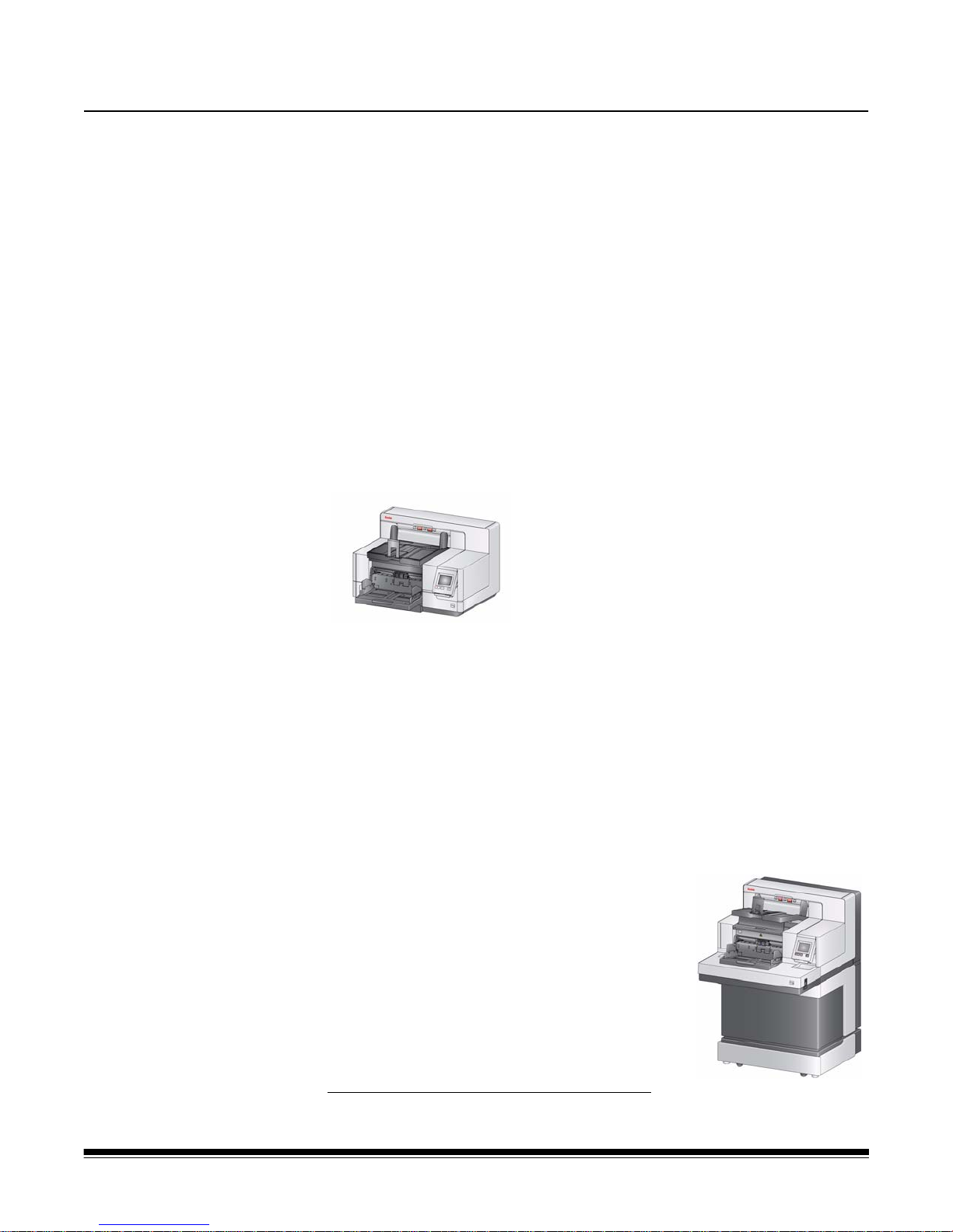
The Kodak i5x50 Scanners include the following models:
Kodak i5250 Scanner — desktop duplex color
scanner that scans up to 150 pages per minute
(200/300 dpi, black and white/color/grayscale,
landscape orientation) A4 size documents with
Kodak Perfect Page technology.
Kodak i5650 Scanner — desktop duplex color
scanner that scans up to 180 pages per minute
(200/300 dpi, black and white/color/grayscale,
landscape orientation) A4 size documents with Kodak Perfect Page
technology.
Kodak i5250V Scanner — desktop duplex color scanner that scans up to 150
pages per minute (200/300 dpi, black and white/color/grayscale, landscape
orientation) A4 size documents, with Kofax VRS
CGA hardware.
Kodak i5650V Scanner — desktop duplex color scanner that scans up to 180
pages per minute (200/300 dpi, black and white/color/grayscale, landscape
orientation) A4 size documents, with Kofax VRS
CGA hardware.
Kodak i5850 Scanner — floor-standing duplex
color scanner that scans up to 210 pages per
minute (200/300 dpi, black and white/color/
grayscale, landscape orientation) A4 size
documents with Kodak Perfect Page technology.
This User’s Guide provides information and
procedures for using and maintaining the Kodak
i5x50 Scanners. The information in this guide is for
use with all models unless otherwise noted.
VRS is a registered trademark of Kofax.
®
Professional with built-in
®
Professional with built-in
A-61845 January 2016 1-1

NOTES:
• Most of the illustrations in this guide show the Kodak i5250/i5650 Scanner.
• Kodak i5250V/i5650V Scanners are intended to work with Kofax VRS
enabled applications. Kodak Perfect Page technology is not supported on
these models.
Supporting
documentation
In addition to this User’s Guide, the following documentation is also available:
• Installation Guide — provides a step-by-step procedure for installing the
scanner.
• Scanning Setup Guides — the TWAIN Datasource and ISIS Driver are
included with the Kodak i5x50 Scanners. VRS is included with the Kodak
i5250V/i5650V Scanners only. Each Scanning Setup Guide explains how to
use basic image processing features. All Scanning Setup Guides are
provided on the Installation CD/DVD in PDF format and are also available to
download from the Kodak Alaris website:
www.kodakalaris.com/go/scanners.
• Reference Guide — provides easy visual steps for cleaning your scanner.
Keep this guide close to the scanner so you can use it as an easy re ference.
Accessories See the section entitled, “Supplies and consumables” in Chapter 7 for catalog
numbers for the following accessories.
Kodak Enhanced Printer Accessory (Front and Rear) — provides an
effective way to apply information to the scanned document. It operates at full
scanner speed. The printer can add a date, time, document sequential cou nter
and custom messages. See Chapter 4, Document Printing for more
information.
Kodak Manual Feed Shelf — when the need arises to manually feed
documents, the Manual Feed Shelf provides a flat work surface to aid in
single-sheet feeding. The Manual Feed Shelf can be easily installed and
removed. The Kodak Manual Feed Shelf comes with the shelf and two side
guides which can be adjusted to the desired position for scanning.
Kodak Lead Edge Alignment Exit Tray Accessory— use this accessory
when you want the edges of your documents to align against the outp ut tray
document stop after scanning.
1-2 A-61845 January 2016
Document Extenders — document extenders are available fo r scanning
documents longer than 43.2 cm (17 inches). These extenders are available in
66.04 cm, 76.2 cm and 86.36 cm (26-, 30-, and 34-inch) lengths.
Kodak Feeder Kit for Ultralightweight Paper — allows you to feed
2
lightweight paper from a paper weight ra nge of 25 g/m
(7 to 20 lbs). The Kodak Feeder Kit for Ultralightweight Paper includes a feed
module and separation roller that are specially designed to feed lightweight
paper through the scanner transport.
Kodak Dual Controlled Stacking Accessory (for i5850 only) — allows
physical stacking of the scanned document s, based on size or the presence o f
a patch code on a document. It also chooses the stacking location of a
document that is triggered by a multifeed event.
Kodak Rear Exit Tray for the i5250 and i5650 Scanners — attaches to the
rear of the scanner and allows documents to be deposited directly into this
tray.
to 80 g/m
2

What’s in the box Before you begin open the box and check the contents:
• Kodak i5250, i5650, i5250V, i5650V or i5850 Scanner
• Output tray
• Short document adapter
• USB cable
• AC power cord bundle
• Replacement tires and pre-separation pads
• Rear exit tray (for i5850 Scanner only)
• Welcome Folio which includes:
- Installation CD/DVD
- Application CDs/DVD
- Dangler extensions
- Printed User’s Guide, English
- Printed Reference Guide (multi-languages)
- Printed Installation Guide
- Sample Cleaning Kit
- Miscellaneous flyers/Safety sheets
NOTE: The purchase of a Kodak i5850 Scanner includes unpacking and
installation by a field service representative. Customers should not
unpack/install the Kodak i5850 Scanner. For more information
regarding installation of the i5850 Scanner, go to:
www.kodakalaris.com/go/IMcontacts.
A-61845 January 2016 1-3
Scanner components
9
8
7
6
5
4
3
2
1
10
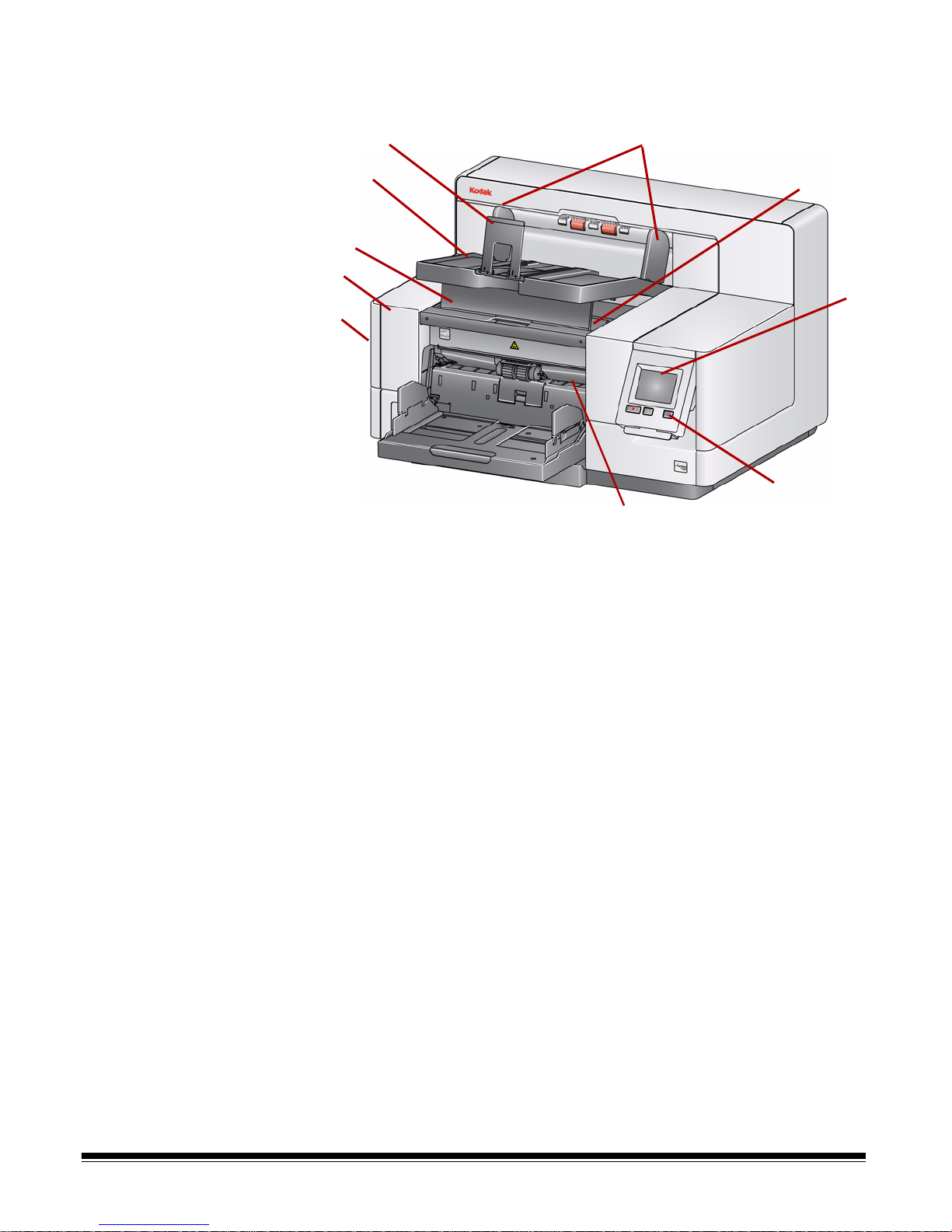
Front view: all models
1 Scanner cover release latch (not shown in this illustration) — located on
the left side of the scanner; pull the lever forward to open the scanner
cover.
2 Scanner cover — provides access to the internal components.
3 Output tray height adjustment tab — this tab should be pulled out to
raise the front of the output tray when scanning for improved document
stacking. When the output tray is lifted, this tab automatically releases
and rests on the printer access cover.
4 Output tray — collects the scanned documents.
5 Document stop — aids in document stacking. You can slide this stop in
or out to accommodate the size of documents you are scanning or it can
be folded flat on the output tray.
6 Output tray side guides — can be moved in and out to accommodate
document size or folded flat on the output tray.
7 Front printer access cover — (located underneath the output tray) lift
this cover to access the feed module release knob and the optional
Enhanced Printer for changing printer positions and maintenance. The
scanner serial number and K number are also located in this area.
8 Touchscreen/Operator Control Panel — a variety of functions can be
performed using the touchscreen. See Chapte r 3 for procedur es on using
these functions.
9 Power button — press to turn the scanner on or press and hold for two
seconds to put the scanner into low power mode.
1-4 A-61845 January 2016
10 Feed module release lever — push this lever to the right to release the
feed module for cleaning or replacement. When using this release lever,
the scanner cover must be open.
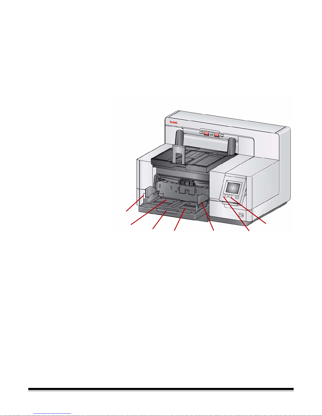
11 Start/Resume button — press to start or resume scanning.
17
11
12
1314
15
16
12 Stop/Pause button — press once to temporarily pause scanning (the
Star t/Resume button can then be used to resume scanning). Press twice
to stop scanning.
13 Input Elevator side guide s — slide the guides in or out to accommo date
the document size you want to scan. Side guides can be left-, cente r- and
right-adjusted to accommodate documents of various widths. The side
guides can also be locked into position.
Fold the side guides down when you want to close the input elevator
when the scanner is not in use.
A-61845 January 2016 1-5
14 Input Elevator — holds up to 750 documents (20 lb./80 g/m
2
) in place.
The input elevator can be set to accommodate stacks of 25, 100, 250,
500 or 750 documents. The input ele vator can be folded up when it is n ot
in use.
15 Input Eleva tor extender — pull this extender out to accommodate
documents longer than 35.6 cm (14 inches).
16 Front print loca tion indicators — if you ar e using the Enhanced Pr inter
Accessory, use the detents at the edge of the input elevator as a visual
guide to see where the printing position will be on the document.
17 Gap release toggle switch (i5250/i5650/i5250V/i5650V Scanners) —
push the “+“ button to increase the space between the feed module and
separation roller for documents that require special handling.
NOTE: The gap release toggle switch is located in a different position on
the i5850 Scanner. See the next section, “Front view: i5850
Scanner” for more information.
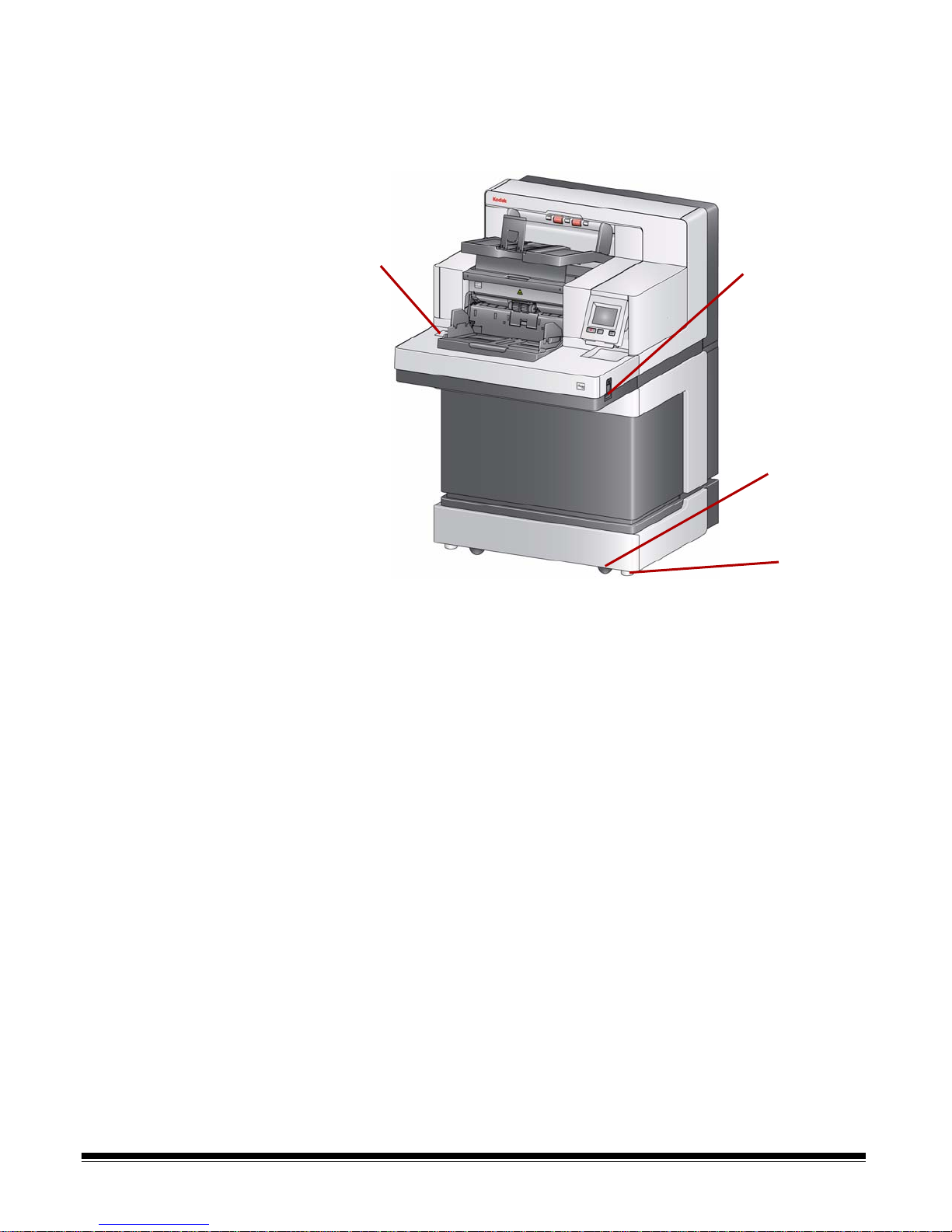
Front view: i5850 Scanner In addition to the components listed previously, the Kodak i5850 Scanner also
Height adjustment
switch
Leveling
Gap release
toggle switch
feet
Castors
has a workspace height adjustment switch which is used to raise and lower the
workspace table on the scanner. The workspace table can be raised or
lowered approximately 10 inches up or down.
There are four castors and four leveling feet on the bottom of the scanner. If
you need to move the scanner, the leveling feet must be raised. Contact
Technical Support before attempting to relocate the scanne
r.
1-6 A-61845 January 2016
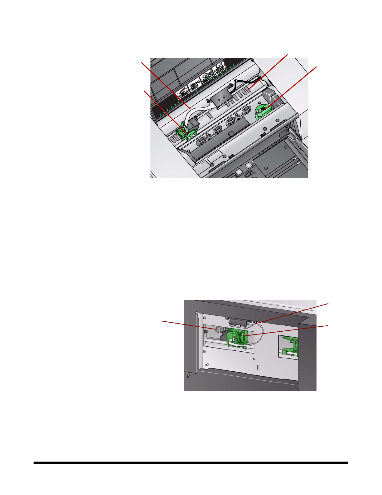
Front printer access view:
3
2
4
1
1
2
3
all models
Even if you do not have the Kodak Enhanced Printer Accessory, you will still
need to access this area of the scanner. The feed module release knob is
located in this area.
1 Feed module release knob — turn this knob to release the feed module
from it’s position for cleaning or replacement. Turn the arrow to right to
disengage the feed module.
The following components are for front printing and are only present if the
Enhanced Printer Accessory is installed.
2 Enhanced Printer carrier/cartridge — allows printing on documents.
3Printer cable — this cable connects directly to the printer carrier to allow
communication to the Enhanced Printer.
4 Print positions — the i5x50 Scanners allow front printing on your
documents. Up to 39 positions are available when using the front printer.
Rear printer access view:
i5850 Scanner only
The following components are for rear printing and are only present if the
Enhanced Printer Accessory is installed.
A-61845 January 2016 1-7
1Printer cable — this cable connects directly to the printer carrier to allow
communication to the Enhanced Printer.
2 Enhanced Printer carrier/cartridge — allows printing on documents.
3 Print positions (located on the underside of the rail) — the i5850
Scanner has the capability of front and rear printing. Up to 24 print
positions are available when using the rear printer . Only one printer (front
or rear) can be used at a time.
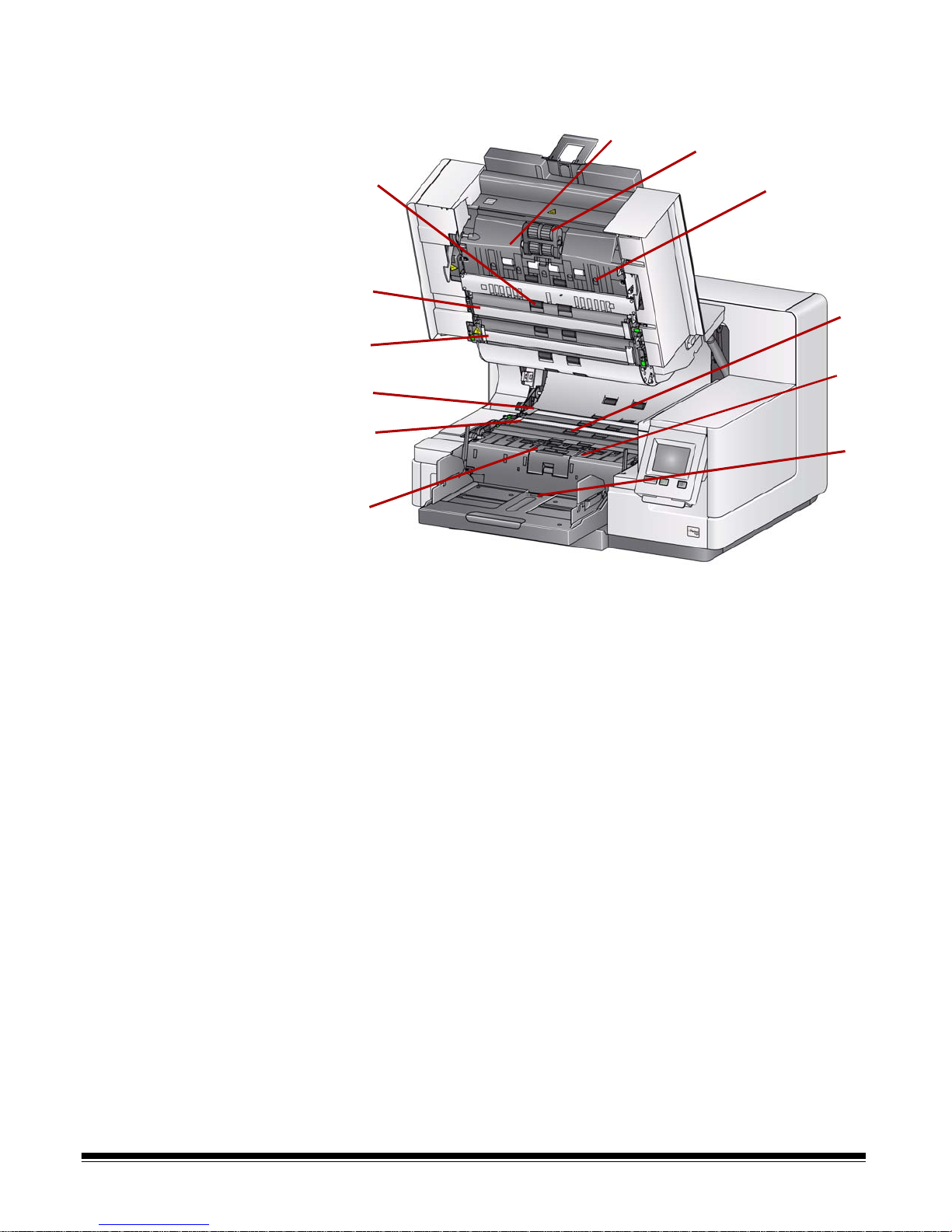
Inside view: all models When you pull the scanner cover release latch forward to open the scanner
1
2
3
3
2
4
6
8
10
5
7
9
cover, the following internal components are visible.
1 Separation roller and pre-separation pad — provides smooth
document feeding and separation of various sizes, thicknesses and
textures of documents.
2 Black/White background — using your scanning application, this
background can be changed to White or Black. Under normal scanning
conditions you would use the black background. If you are scanning
lightweight or thin paper with printing on one side, you can use the white
background to help eliminate bleed-through in the final image. See the
Scanning Setup Guides for TWAIN and ISIS for more information.
NOTE: VRS does not support scanning with a white background.
3 Imaging guides — keep imaging guides clean to obtain optimum image
quality.
4Rollers — provides smooth transport of documents through the scanner.
5 Intelligent document protection sensors — these sensors determine
how aggressively the scanner detects documents that enter the scanner
incorrectly.
6 Feed module — provides smooth document feeding and separ ation of
various sizes, thicknesses and textures of documents.
1-8 A-61845 January 2016
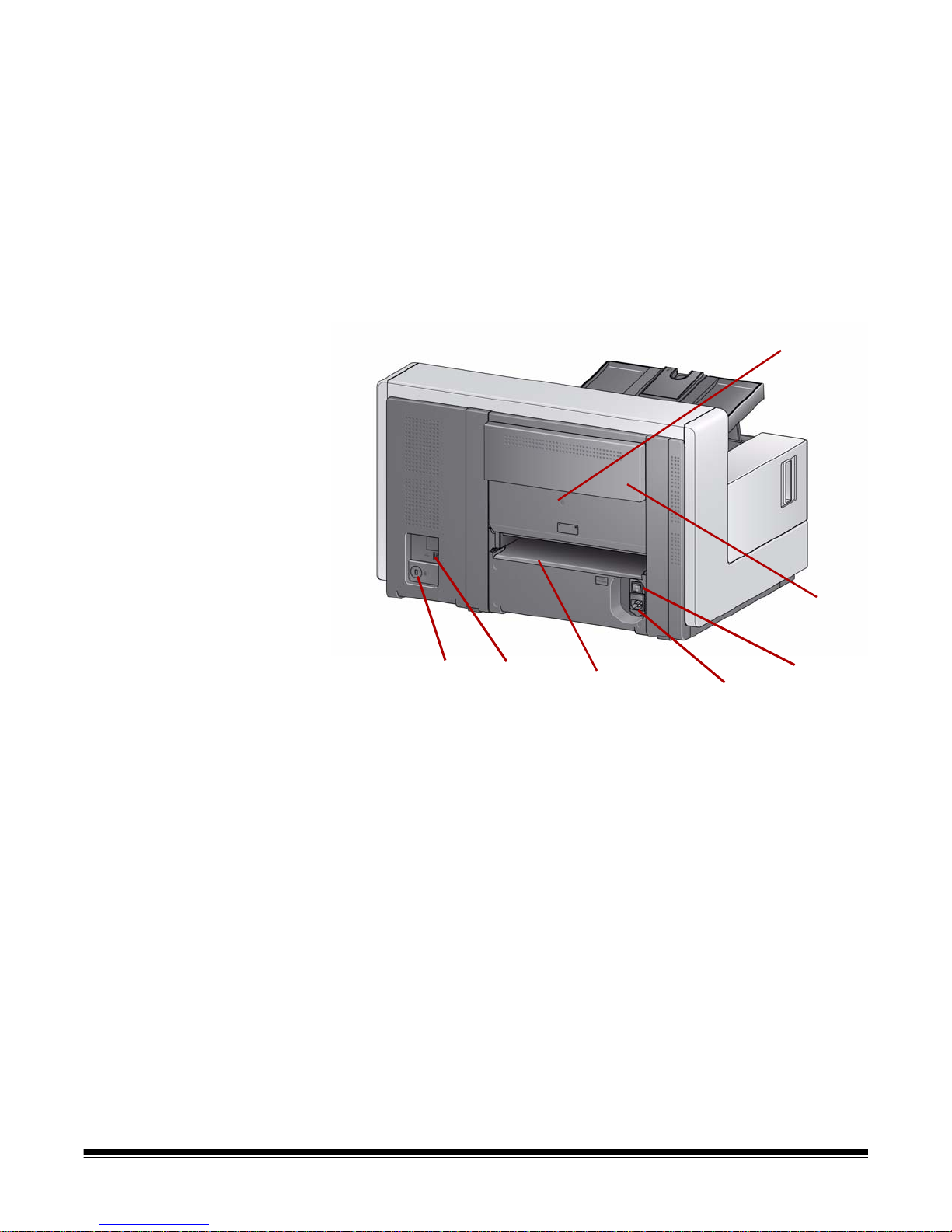
Rear view: i5250/i5650/
4
1
2
3
5
6
7
i5250V/i5650V Scanners
7Sensors — these five ultra son ic se ns or s cove r th e width of the paper
path which aid in detecting multifed documents.
8 Ink blotter channels and ink blotters (located underneath the dr ainage
strip) — the ink blotters which are placed in these channels, collect ink
residue from the optional Enhanced Printer Accessory.
9 Metal detectors — detects any metal (e.g. staples, etc.) before e ntering
the scanner.
10 Paper present se nsor — detects the pr esence of docu ments in the in put
elevator. Documents must be covering this sensor in order for the
scanner to begin scanning.
1 Security lock port — connects a security lock to the scanner. You can
purchase a standard security lock at an office supply store. Refer to the
instructions provided with the security lock for installation procedures.
2USB port — connects the scanner to the PC.
3 Rear document exit — allows you to exit exception documents from the
rear of the scanner.
4 Power port — connects the power cord to the scanner.
5 Main power switch — this switch must be On (I) to activate the power to
the scanner.
6 Rear printer access door — provides access to the rear printer.
7Screw — using a flat-head screwdriver, loosen this screw to rem ove the
rear cover which provide access to the rear printer.
A-61845 January 2016 1-9
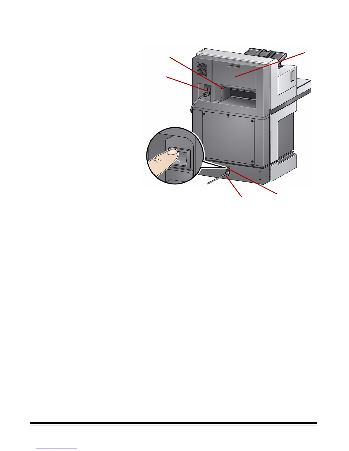
Rear view: i5850 Scanner
1
2
3
4
5
1 Rear document exit — allows you to exit exception documents from the
rear of the scanner.
2 USB port — connects the scanner to the PC.
3 Power port — connects the power cord to the scanner.
4 Main power switch — this switch must be On (I) to activate the power to
the scanner.
5 Rear printer access door — provides access to the rear printer.
1-10 A-61845 January 2016

2Installation
Contents Installing the scanner.................................................................................2-1
Installing the Kodak Driver Software .....................................................2-1
Attaching the output tray........................................................................2-2
Connecting the power cord and USB cable: i5250/i5650/
i5250V/i5650V Scanners...... ... ... .... ... ... ... ... .... ... ... ... .... ... ... ... ... ............2-2
Connecting the power cord and USB cable: i5850 Scanner .................2-3
Turning the scanner on............................................ ... ... .... ... ... ..................2-4
Power modes.............................................................................................2-6
If desired, Kodak Alaris Professional Services provides professional
installation and user training. Contact Technical Support for more details at
www.kodakalaris.com/go/IMsupport.
The following installation procedures are for the Kodak i5250/i5650/i5250V/
i5650V Scanners. Installation by a field service representative is included with
the purchase of a Kodak i5850 Scanner.
Installing the scanner This section provides detailed information supporting the Installation Guide
that is provided with your scanner. Follow these steps in the order they are
provided to install your scanner.
NOTES:
• Before you begin, verify that your host PC meets the system requirements
that are provided in Appendix A, Specifications.
• If you have already performed all of the steps in the Installation Guide, skip
this section.
• Updated drivers may be available at www.kodakalaris.com/go/scanners.
Installing the Kodak Driver
Software
Do not install the USB cable before installing the Driver Software.
1. Insert the Kodak i5x50 or i5x50V Scanner Installation disk in the disk drive.
The installation program starts automatically.
NOTE: If the disk does not start automatically, open the My Computer
icon on your desktop. Double-click the icon indicating your disk
drive, then double-click on setup.exe.
2. Follow the prompts that are displayed until the installation is complete.
3. Remove the Installation disk from the disk drive.
A-61845 January 2016 2-1
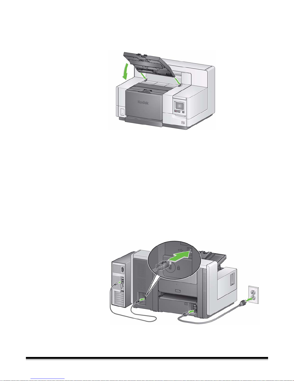
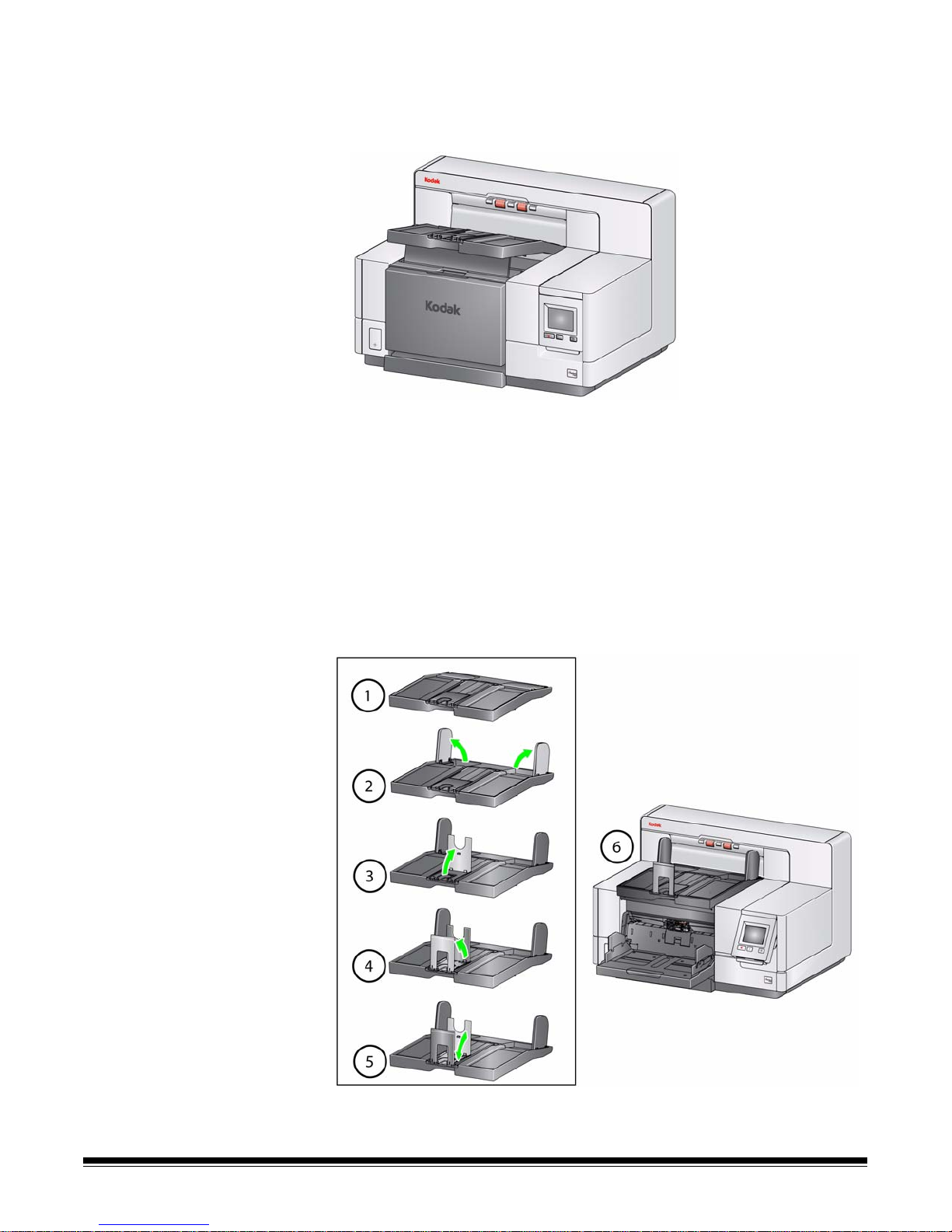
Attaching the output tray When you unpack the Kodak i5x50/i5x50V Scanner, the output tray is packed
in a separate box.
• Locate the output tray slots on the scanner. Angle the output tray and align
the output tray with the slots, slide it into place and lower it into position.
NOTE: Be sure to lift the output tray up to the scanning position before
feeding documents. See the section entitled, “Adjusting the output
tray” in Chapter 3.
Connecting the power cord
and USB cable: i5250/i5650/
i5250V/i5650V Scanners
After the drivers have been installed, connect the power cord and USB cable
to the scanner. Refer to the illustration below for making proper connections.
Make sure the power outlet is located within 1.52 meters (5 feet) of the
scanner and is easily accessible.
1. Select the appropriate AC power cord for your region from the supply of
power cords packed with your scanner.
2. Plug the output power cord into the power port on the scanner. Be sure it is
securely attached.
3. Plug the other end of the power cord into the wall outlet.
4. Attach the USB cable (either USB 2.0 or 3.0) to the scanner USB port.
5. Attach the other end of the USB cable to the proper USB port on your PC.
2-2 A-61845 January 2016
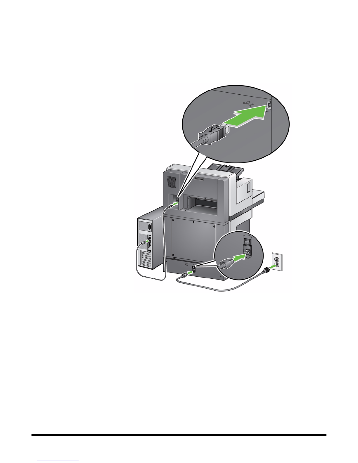
Connecting the power cord
and USB cable: i5850
Scanner
In the event that you need to relocate or move the i5850 Scanner, refer to the
illustration below for making proper connections. Make sure the power outlet is
located within 1.52 meters (5 feet) of the scanner and is ea sily accessible.
1. Select the appropriate AC power cord for your region from the supply of
power cords packed with your scanner.
2. Plug the output power cord into the power port on the scanner. Be sure it is
securely attached.
A-61845 January 2016 2-3
3. Plug the other end of the power cord into the wall outlet.
4. Attach the USB cable (either USB 2.0 or 3.0) to the scanner USB port.
5. Attach the other end of the USB cable to the proper USB port on your PC.
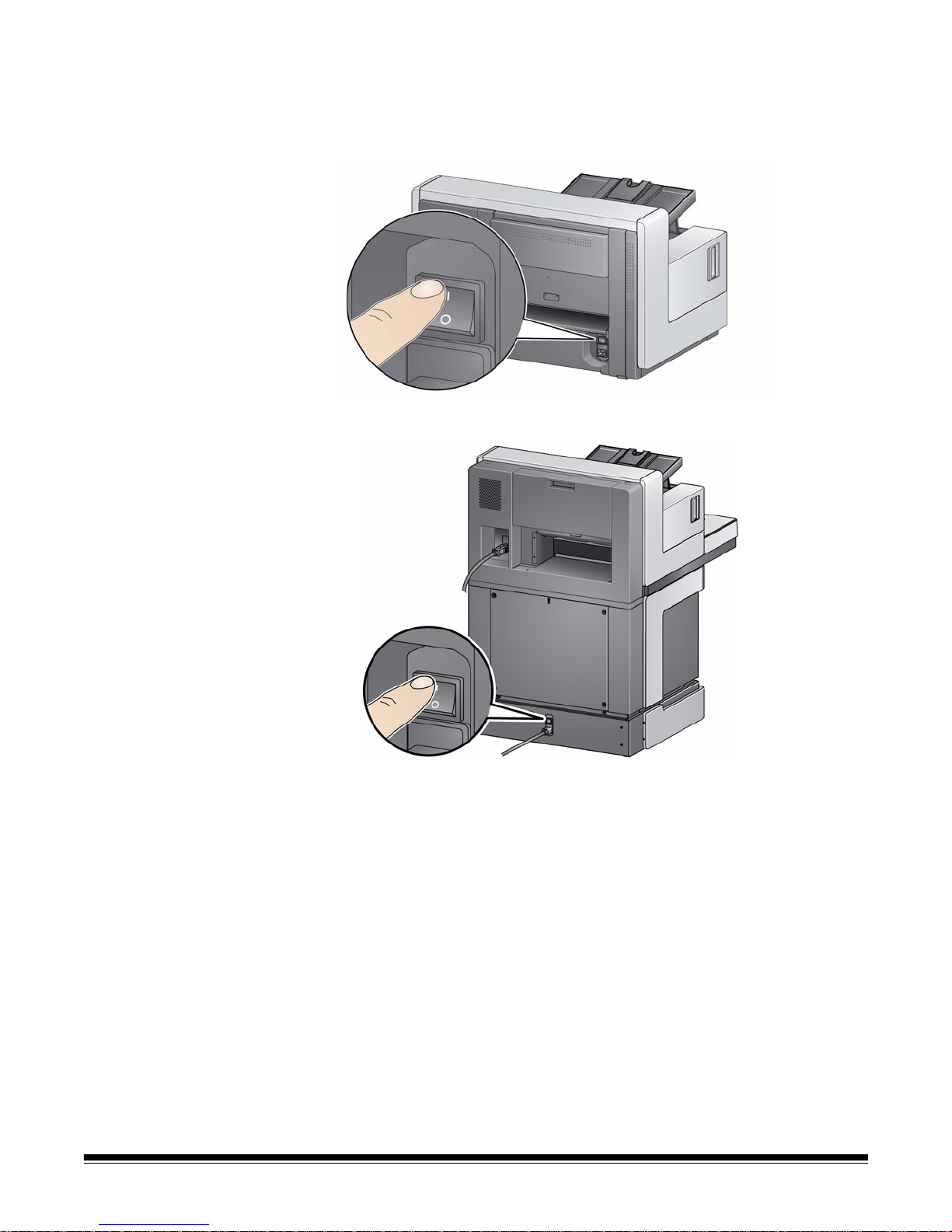
Turning the scanner
i5850 Scanner
i5250/i5650/i5250V/i5650V Scanners
on
1. Press the main power switch on the back of the scanner to the On (I)
position. The LED on the front of the scanner will be a steady yellow and
nothing will be displayed on the Operator Control Panel (this is low power
mode).
2-4 A-61845 January 2016
NOTES:
• It is not necessary to turn the main power switch off unless you are not
going to use the scanner for a prolonged period of time, you are
performing maintenance, you are going to move the scanner or are
directed to turn the power off by a field service representative.
• For the Kodak i5850 Scanner only: There are four leveling feet on the
bottom of the scanner. If you need to move the scanner, these leveling
feet must be raised. Contact a field service representative before
attempting to relocate the scanner.
• Damages incurred when moving a scanner will not be covered by the
Equipment Service Agreement. Kodak Alaris Professional Services
provide relocation services. Go to www.kodakalaris.com/go/IMcontacts
for more information.
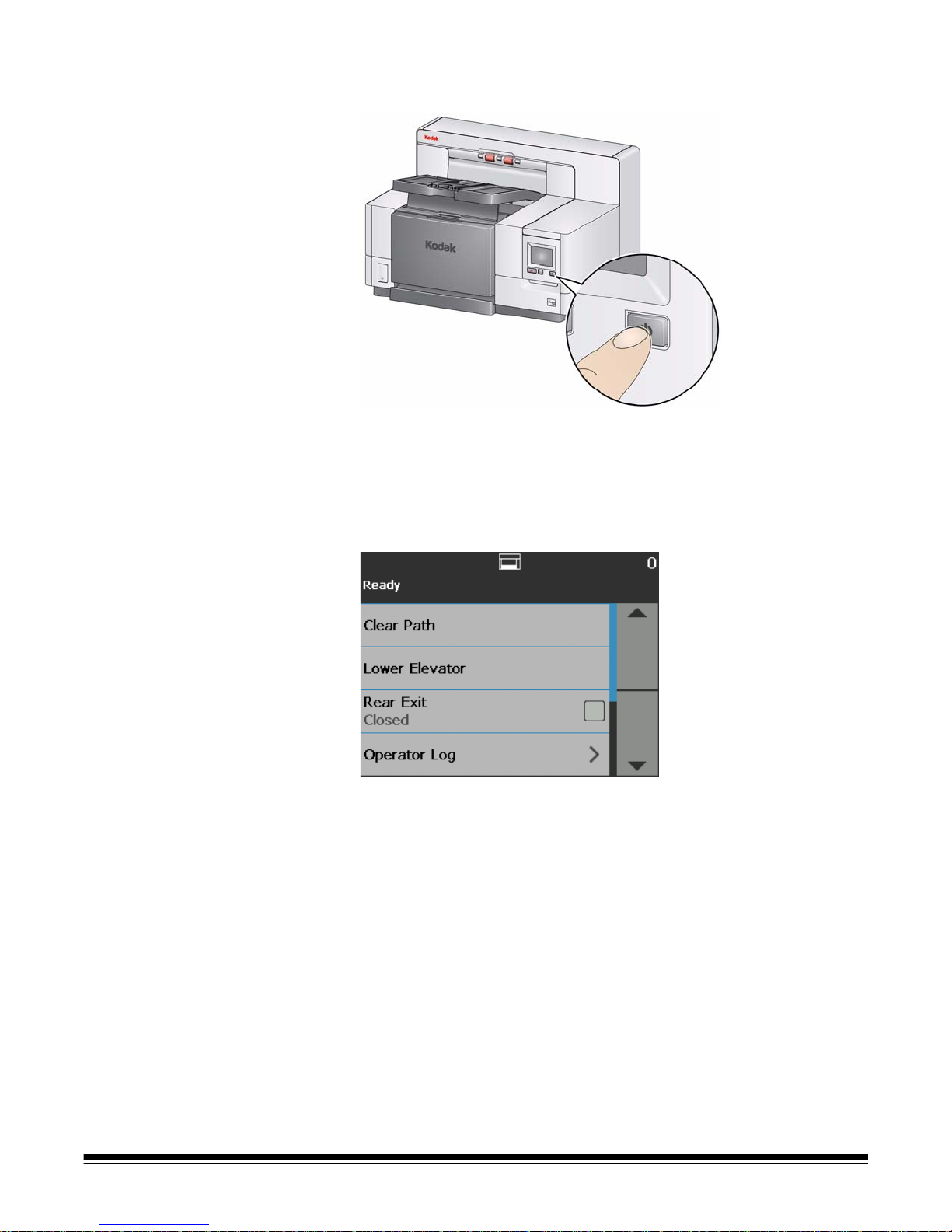
2. Press the Power button on the front of the scanner . The Power butto n LED
will temporarily go off and the Operator Control Panel will remain blank.
After a few seconds the initialization screen will be displayed, and the
Power LED will be a steady yellow.
During the initialization process, if the scanner input elevator is closed, it
will automatically open. When the scanner goes to the Ready mode, the
Power LED will turn a steady green, the scanner will sound an alert (if your
Volume setting is not set to Off) and the Ready screen will be displayed.
A-61845 January 2016 2-5

Power modes The following chart provides information regarding the power modes of the
scanner, LED status and the manual or automatic action that will put the
scanner into a given power mode.
Mode LED Power consumption Action
Scanner off Off 0 watts
Standby Steady yello w < 1 watt
Low Power
Flashing
yellow
< 4 watts
< 115 watts
not scanning
(all models)
< 215 watts
scanning
(i5250/i5650)
Turn the power switch on the back of the scanner to
the Off position (O).
This is the mode the scanner is in when the power is
first turned on (the power switch on the back of the
scanner is in the On position [I]).
The scanner goes from Low Power mode to Standby
mode by pressing the Power button for more than 2
seconds.
The scanner goes from Ready mode to Low Power
mode by pressing the Power button for more than 2
seconds.
The scanner goes from Standby mode to Ready
mode by:
• Pressing the Power button, or
• placing paper in the input elevator.
The scanner goes from Low Power mode to Ready
mode by:
Ready Steady green
< 250 watts
scanning
(i5850)
< 350 watts
scanning and lift
operation
(i5850)
• Pressing the Power button, or
• placing paper in the input elevator, or
• pressing the Start/Resume button, or
• receiving a host command.
2-6 A-61845 January 2016

3Scanning
Contents Getting your scanner ready to scan...........................................................3-2
Adjusting the input elevator....................................................................3-2
Installing the optional document extender..............................................3-4
Adjusting the output tray ........................................................................3-4
Changing the dangle extensions............................................................3-6
Installing the short document adapter....................................................3-6
Adjusting the height of the scanner (i5850 Scanner only)......................3-7
Using the rear document exit .................................................................3-8
Installing the rear document exit tray accessory....................................3-9
Getting your documents ready to scan .................................................... 3-11
Scanning documents............................................. ... ... ... .... ... ... ... ... ..........3-12
Pausing and resuming scanning..........................................................3-13
Using the Operator Control Panel touchscreen .......................................3-13
Ready screen....................................... ... ... ... .... ...................................3-14
Clearing the Paper Path...................................................................3-15
Lowering the Elevator.......................................................................3-15
Toggle Counter .................................................................................3-15
Rear Exit...........................................................................................3-16
Viewing the Operator Log.................................................................3-16
Viewing Scanner Information............................................................3-17
Diagnostics.......................................................................................3-17
Ready screen when Indexing is enabled in the scanning
application......................................................................................3-26
Settings screen ....................................................................................3-29
User Counter....................................................................................3-30
Automatic Elevator ...........................................................................3-30
Staple/Metal Protection.....................................................................3-31
Changing the alarm volume..............................................................3-31
Selecting the sound..........................................................................3-32
Units .................................................................................................3-32
Misfeed OCP Control........................................................................3-33
Dual Stacking Toggle Patch....... .... ... ... ... ... .... ... ... .............................3-33
Overrides..............................................................................................3-34
Application Overrides .......................................................................3-36
Reset All Settings.............................................................................3-44
A-61845 January 2016 3-1

Getting your scanner
ready to scan
1. Be sure the scanner is on and in Ready mode (Power button LED is green
and constant).
2. Adjust the input elevator to meet your scanning needs. See the next
section entitled, “Adjusting the input elevator”.
3. Adjust the output tray to meet your scanning needs. See the section
entitled, “Adjusting the output tray” later in this chapter.
4. Select your scanning application.
NOTE: The illustrations in this chapter show the i5250/i5650/i5250V/i5650V
Scanner. All adjustm ents are the same for the i5850 Scanner unless
otherwise noted.
Adjusting the input
elevator
You can adjust the side guides and input elevator height to accommodate your
scanning needs. When the scanner is not in use, the input elevator can be
folded up against the scanner.
NOTE: The input elevator must be in the lowest position and the elevator side
guides must be folded down before closing it.
• Adjusting the side guides — the side guides can be adjusted for right-
edge, left-edge or center feeding. The side guides can be moved together
for center feeding or independently for offset feeding (right-edge or left-
edge). Before moving the side guides, be sure th e lo cking switch is not in
the locked position (see below).
NOTE: When using the optional Enhanced Printer, documents should be
placed in the input elevator in a manner that will align the print
string in the proper location. See Chapter 4, Document Printing for
more information.
3-2 A-61845 January 2016
• Locking the side guides — side guides may be locked into position after
they are adjusted. This is helpful when the placement of a print string is
important.
To lock the side guides remove any documents from the input elevator and
move the lock switch to the left (the locked position).
• Adjusting the height of the input elev ator — the input elevato r can be set
to accommodate stacks of 25 or less, 100, 250, 500 or 750 documents of
20 lb./80 g/m2 bond paper. Input elevator settings are made through your
scanning application software (i.e., TW AIN Data source, ISIS Driver or VRS).
If the input elevator is set to ADF mode (using the TWAIN Data source or the
ISIS Driver), or the Feed Source is set to Manual (VRS), then the input
elevator will remain in the up position (i.e., 25 documents or less). When set
to more than 25, the input elevator will automatically raise to feed
documents and lower after the last document in your stack has been fed.
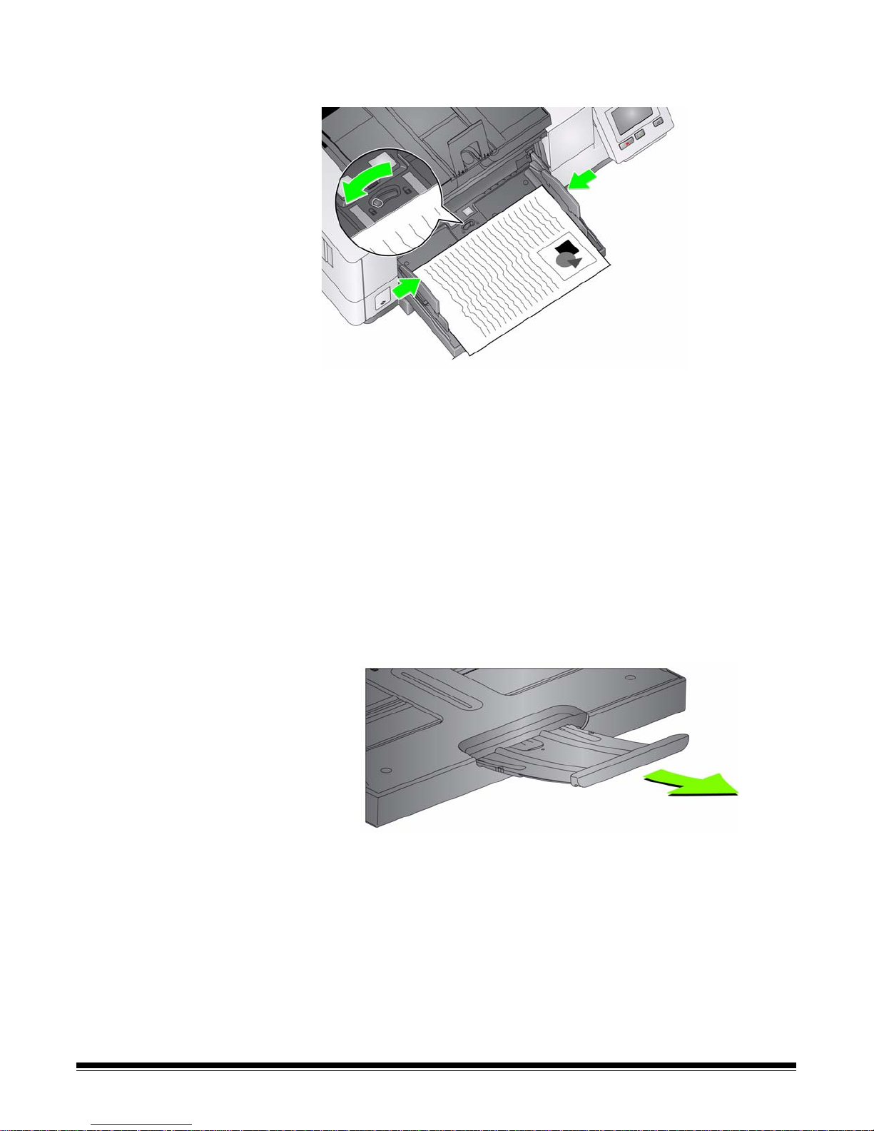
• Adjusting the input elevator
- Document lengths up to 35.6 cm (14 inches) — no adjustments are
required.
- Document lengths from 35.6 to 43.2 cm (14 to 17 inc hes) — slowly pull
out the document extender.
- To push the extend er back into place, positio n your fingers on the sides of
the extender (at the arrows on the extender) and squeeze and slide the
extender back into place.
NOTES:
• Operator assistance may be required for scanning documents greater
than 43.2 cm (17 inches).
A-61845 January 2016 3-3
• If you are scanning documents longer than 43.2 cm (17 inches), the
scanning application must be set to accommodate these long
documents. Be sure to verify that the Maximum Length option on the
Device-General tab (TWAIN Datasource) or the Longest Document
option on the Scanner tab (ISIS Driver) is set to slightly longer than the
longest document being scanned. Setting a length longer than needed
may impact throughput.
• For i5250V and i5650V Scanners: these scanners have a set
maximum Document Length of 40 inches; therefore, no adjustment is
necessary.
• It is recommended that you use a document extender if you are
scanning documents longer than 43.2 cm (17 inches). Thre e sizes of
document extenders are available for scanning documents from
43.2 cm (17 inches) to 86.36 cm (34 inches). See the section entitled,
“Supplies and consumables” in Chapter 7 for ordering information.
• Document weights — the maximum document weight for the input
elevator is the approximate weight of a 500-sheet ream of A3 (11 x 17inch) paper or a 750-sheet ream of A4 (8.5 x 11) paper. If you are
scanning documents larger than A3 (11 x 17-inch), the recommended
weight capacity should not exceed 4.5 kg (10 pounds). If the documents
you are scanning are larger than A3 (11 x 17-inch), scan less than 100
sheets at a time.
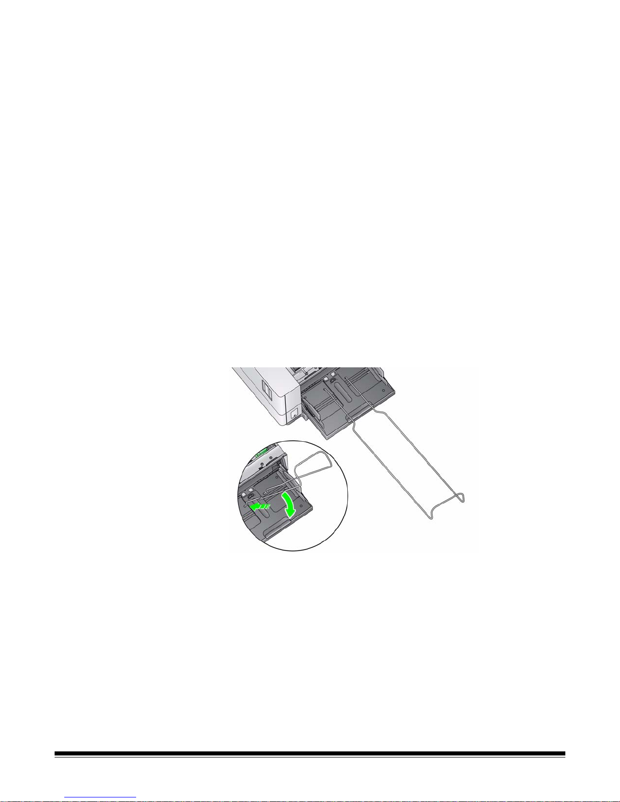
Installing the optional
document extender
• Insert the ends o f the document extender into the holes on the in put elevator
and the output tray and lower the extender into position.
Adjusting the output tray Various document handling settings are available to adjust the way that
documents are placed into the output tray (via the TWAIN Datasource, ISIS
Driver or VRS). The highest throughput can be obtained by scanning
documents of similar size using the output tray side guides and end stop with
Normal document handling.
3-4 A-61845 January 2016
Other document handling options are ava ilab l e fo r bette r ha nd lin g whe n
scanning documents of varying size and thickness.
• Adjusting the angle of the output tray — it is strongly recommended that
you scan documents with the angle of the output tray in the “up” position to
achieve best stacking performance. Just lift the front of the output tray and
the height adjustment tab will release from underneath the output tray.
To lower the output tray , gently push the height adjustment tab underneath
the output tray while lowering the output tray on to the front printer access
cover.
• Adjusting the side guides and document st op — the side guides and
document stop can be adjusted in a variety of ways. Open and adjust the
side guides on the output tray to match the position of the side guides on the
input elevator. The side guides can also be folded flat against the output
tray.
Adjust the output tray document stop to slightly longer than the longest
document being fed. If you are scanning documents longer than the output
tray will accommodate, fold the document stop flat on the output tray.
A-61845 January 2016 3-5
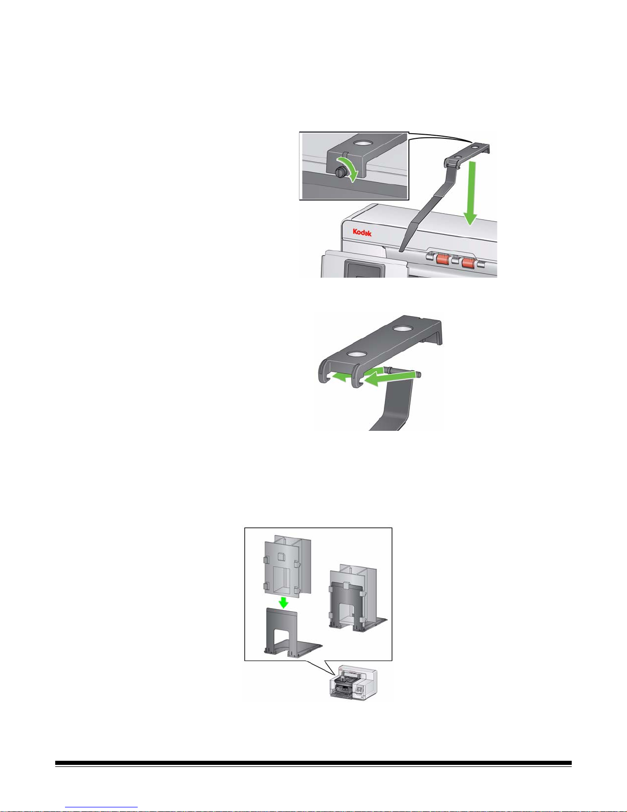
Changing the dangler
extensions
The scanner comes with a mount and danglers, which can easily be changed
based on the document set you are scanning.
If desired, attach the mount to the top of the scanner. The dangler helps align
the documents as they are deposited in the output tray. Three sizes of the
danglers are available. Depending on the document set you are scanning,
attach the size of the dangler that meets your needs.
NOTE: T o change the dangler remove th e mount, unclip the dangler and sna p
the desired dangler into the slots as shown.
Installing the short
document adapter
The short document adapter can be used when scanning small documents
(e.g., checks). This adapter aids in better document stacking.
1. Open the document stop on the output tray as shown in the illustration.
2. Slide the short document adapter over the document stop and push it all
the way down.
3. Adjust the sides guides if necessary.
3-6 A-61845 January 2016
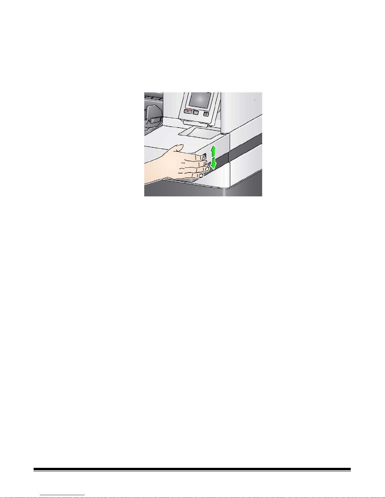
Adjusting the height of the
scanner (i5850 Scanner
only)
The workspace table can be raised approximately 25.4 cm (10 in.) from its
lowest position for your comfort when you are sitting or standing at the
scanner. When you are raising or lowering the workspace table, be sure that
there is nothing close to the scanner that would interfere with the upward and
downward movement (e.g., chair, table, etc.).
• Press the upper portion of the button on the side of the scanner to raise to
workspace table.
• Press the lower portion of the button on the side of the scanner to lower the
workspace table.
If the workspace table will not move up or down from its position, check the
following:
• Be sure the workspace table is not already in its highest or lowest position.
• Be sure the scanner is on and is not in Low Po wer mode.
A-61845 January 2016 3-7
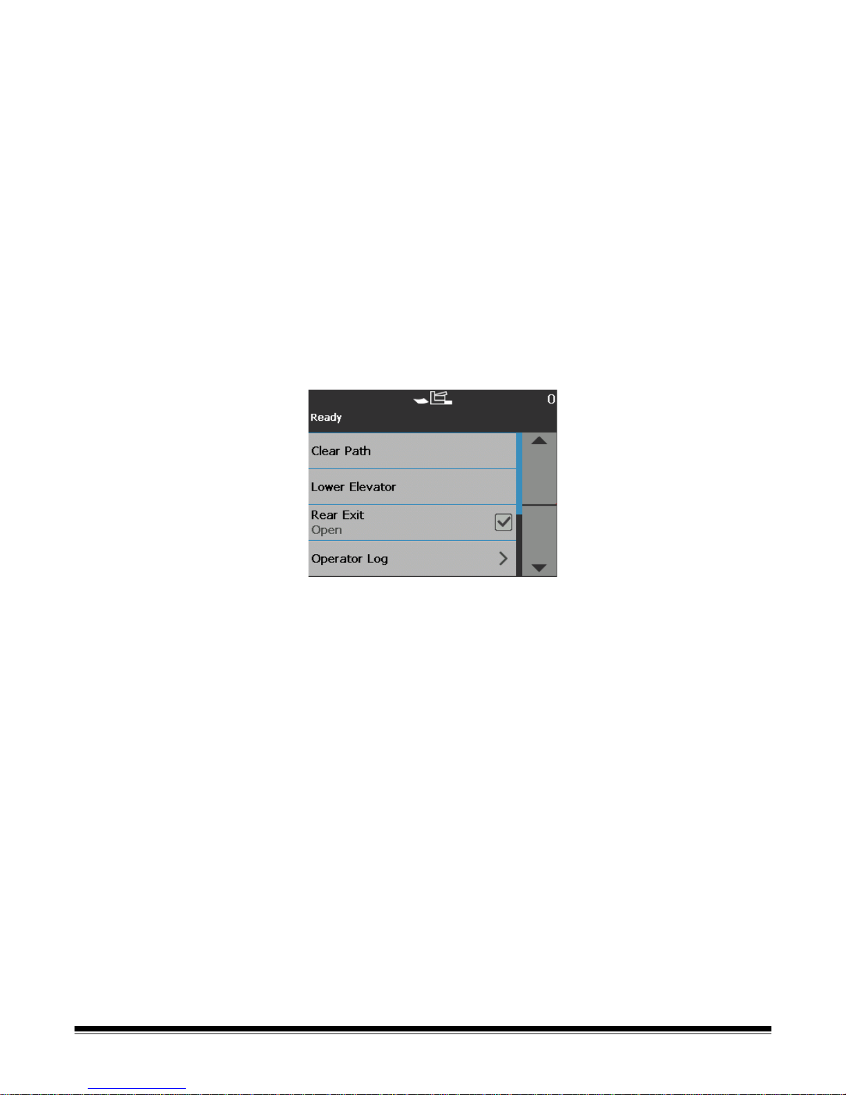
Using the rear document
exit
Documents that require special handling (e.g., fragile documents, shipping
envelopes, etc.) can be output using the rear document exit. This exit provides
the straight-through paper p ath option that allows an exception document(s) to
pass straight through the transport, thus reducing the possibility of a document
jam.
Use the rear document exit when:
• documents are too stiff (e.g., rigid) to make the turn in the transport and are
jamming.
• documents are fragile and you do not want to bend them.
• output stacking order is not important.
• scanning directly into the recycle bin when documents are no longer needed
after scanning.
• scanning photographs.
NOTES:
•Select Rear Exit from the Operator Control Panel.
• Be sure that you have adequate clearance behind the scanner to feed the
document(s) through when using this option.
• When scanning several documents through the rear document exit, the
documents will be output in the reverse scanning order.
• If you have the Rear Exit Tray Accessory, be sure it is attached. See
“Accessories” in Chapter 1 for more information.
3-8 A-61845 January 2016
 Loading...