

Kodak i4250, i4850, i4650 User Manual


3rd Party Licenses
This software is based in part on the work of the Independent JPEG Group
Copyright (C)2009-2013 D. R. Commander. All Rights Reserved.
Redistribution and use in source and binary forms, with or without modification, are permitted provided that the
following conditions are met:
- Redistributions of source code must retain the above copyright notice, this list of conditions and the following
disclaimer.
- Redistributions in binary form must reproduce the above copyright notice, this list of conditions and the
following disclaimer in the documentation and/or other materials provided with the distribution.
- Neither the name of the libjpeg-turbo Project nor the names of its contributors may be use d to endorse or
promote products derived from this software without specific prior written permission.
THIS SOFTWARE IS PROVIDED BY THE COPYRIGHT HOLDERS AND CONTRIBUTORS "AS IS", AND ANY
EXPRESS OR IMPLIED WARRANTIES, INCLUDING, BUT NOT LIMITED TO, THE IMPLIED WARRANTIES OF
MERCHANT ABILITY AND FITNESS FOR A PARTICULAR PURPOSE ARE DISCLAIMED. IN NO EVENT SHALL
THE COPYRIGHT HOLDERS OR CONTRIBUTORS BE LIABLE FOR ANY DIRECT, INDIRECT, INCIDENTAL,
SPECIAL, EXEMPLARY, OR CONSEQUENTIAL DAMAGES (INCLUDING, BUT NOT LIMITED TO,
PROCUREMENT OF SUBSTITUTE GOODS OR SERVICES; LOSS OF USE, DATA, OR PROFITS; OR
BUSINESS INTERRUPTION) HOWEVER CAUSED AND ON ANY THEORY OF LIABILITY, WHETHER IN
CONTRACT, STRICT LIABILITY, OR TORT (INCLUDING NEGLIGENCE OR OTHERWISE) ARISING IN ANY
WAY OUT OF THE USE OF THIS SOFTWARE, EVEN IF ADVISED OF THE POSSIBILITY OF SUCH DAMAGE.

Safety
User Precautions
• Place the scanner on a sturdy, level work surface capable of supporting 30.4 kg (67 lbs) and leave adequate clearance on all
sides of the scanner.
• When relocating the scanner, it is recommended that two people lift the scanner and use safe lifting techniques.
• Do not install the scanner in a location subject to dust, humidity or steam. This may cause electrical shock or a fire. Only use
the scanner indoors in a dry location.
• Make sure the electrical power outlet is located within 1.52 meters (5 feet) of the scanner and is easily accessible.
• When disconnecting equipment from the electric socket, be sure to grasp the plug, not the cord.
• Be sure the power cord is securely plugged into the wall outlet. Failure to do so may cause electrical shock or fire.
• Do not damage, knot, cut or modify the power cord or use a damaged power cord. This may cause electrical shock or fire.
• The scanner requires a dedicated and properly grounded power outlet. Do not use an extension cord or power strip with the
scanner.
• Leave sufficient space around the power outlet so it can be easily unplugged in case of an emergency.
• Do not use the scanner if it becomes inordinately hot, has a strange odor, emits smoke, or makes unfamiliar noises.
Immediately stop the scanner and disconnect the power cord from the power outlet. Contact Service.
• Do not disassemble, service or modify the scanner except as explained in the User’s Guide.
• Do not move the scanner with the power cord and interface cable attached. This may cause damage to the cord/cable.
Remove the power cord from the wall outlet before moving or relocating the sca nner.
• Follow the cleaning procedures recommended by Kodak Alaris. Do not use air, liquid or gas spray cleaners. These cleaners
displace dust, dirt and debris to other locations within the scanner, which may cause the scanner to malfunction.
• Material Safety Data Sheets (MSDS) for chemical products are available on the Kodak Alaris website at:
www.kodakalaris.com/go/msds. When accessing the MSDSs from the website, you will be required to provide the catalog
number of the consumable you want the Material Safety Data Sheet for. See the section entitled, “Supplies and
consumables” later in this guide for supplies and catalog numbers.
Users and their employers need to observe the common sense precautions applicable to the operation of any machinery. These
include, but are not limited to, the following:
• Do not wear loose clothing, unbuttoned sleeves, etc.
• Do not wear loose jewelry, bracelets, bulky rings, long necklaces, etc.
• Hair length should be kept short, using a hair net if needed, or tying long hair up in a bundle.
• Remove all other loose objects from the area that could be drawn into the machine.
• Take sufficient breaks to maintain mental alertness.
• Use only the recommended cleaning supplies.
• Do not use canned/compressed air.
Supervisors should review their employee practices and make compliance with these precautions a part of the job description
for operation of the scanner or any mechanical device.
Warning labels
CAUTION: Moving parts, avoid contact.
CAUTION: Hot surface, avoid contact.

Environmental information
•The Kodak i4250, i4650 and i4850 Scanners are designed to meet worldwide enviro nmental requiremen ts.
• Guidelines are available for the disposal of consumable items that are replaced during maintenance or service; follow local
regulations or contact Kodak Alaris Inc. locally for more information.
• Disposal of this equipment may be regulated due to environmental considerations. For disposal or recycling information,
contact your local authorities or, in the USA, visit: www.kodakalaris.com/go/scannerrecycling.
• The product packaging is recyclable.
• Kodak i4000 Series Scanners are Energy Star compliant and shipped from the factory with the default time set to 15 minutes.
European Union
This symbol indicates that when the last user wishes to discard this product, it must be sent to appropriate
facilities for recovery and recycling. Please contact your local Kodak Alaris representative or refer to
www.kodakalaris.com/go/recycle for additional information on the collection and recovery programs available for
this product.
Please consult www.kodakalaris.com/go/REACH for information about the presence of substances included on the candidate
list according to article 59(1) of Regulation (EC) No. 1907/2006 (REACH).
Acoustic emission
Maschinenlärminformationsverordnung – 3, GSGV
Der arbeitsplatzbezogene Emissionswert beträgt <70 dB(A).
[Machine Noise Information Ordinance — 3, GSGV
The operator-position noise emission value is <70 dB(A).]
EMC statements
United States: This equipment has been tested and found to comply with the limits for a Class B digital device pursuant to Part
15 of the FCC rules. These limits are designed to provide reasonable protection against harmful interference in a residential
installation. This equipment generates, uses, and can radiate radio frequency energy and, if not installed and used in
accordance with the instruction manual, may cause harmful interference to radio communications. However, there is no
guarantee that interference will not occur in a particular installation. If this equipment does cause harmful interference to radio or
television reception, which can be determined by turning the equipment off and on, the user is encouraged to try to correct the
interference by one or more of the following measures:
• Reorient or relocate the receiving antenna.
• Increase the separation between the equipment and receiver.
• Connect the equipment into an outlet on a circuit different from that to which the receiver is connected.
• Consult the dealer or an experienced radio/TV technician for additional suggestions.
Any changes or modifications not expressly approved by the party responsible for compliance could void the user’s authority to
operate the equipment. Where shielded interface cables have been provided with the product or specified additional
components or accessories elsewhere defined to be used with the installation of the product, they must be used in order to
ensure compliance with FCC regulation.
Korea: As this equipment has obtained EMC registration for household use, it can be used in an area including residential
areas.
Japan: This is a Class B product based on the standard of the Voluntary Control Council for interference by information
Technology Equipment (VCCI). If this is used near a radio or television receiver in a domestic environment, it may cause radio
interference. Install and use the equipment according to the instruction manual.

OVERVIEW 1-1
INSTALLATION 2-1
SCANNING 3-1
DOCUMENT PRINTING 4-1
MAINTENANCE 5-1
TROUBLESHOOTING 6-1
APPENDICIES
1 Overview
Contents Supporting documentation.........................................................................1-1
Accessories................................................................................................1-2
What’s in the box........................................................................................1-2
Scanner components........................................ .... ... ... ... .... ........................1-3
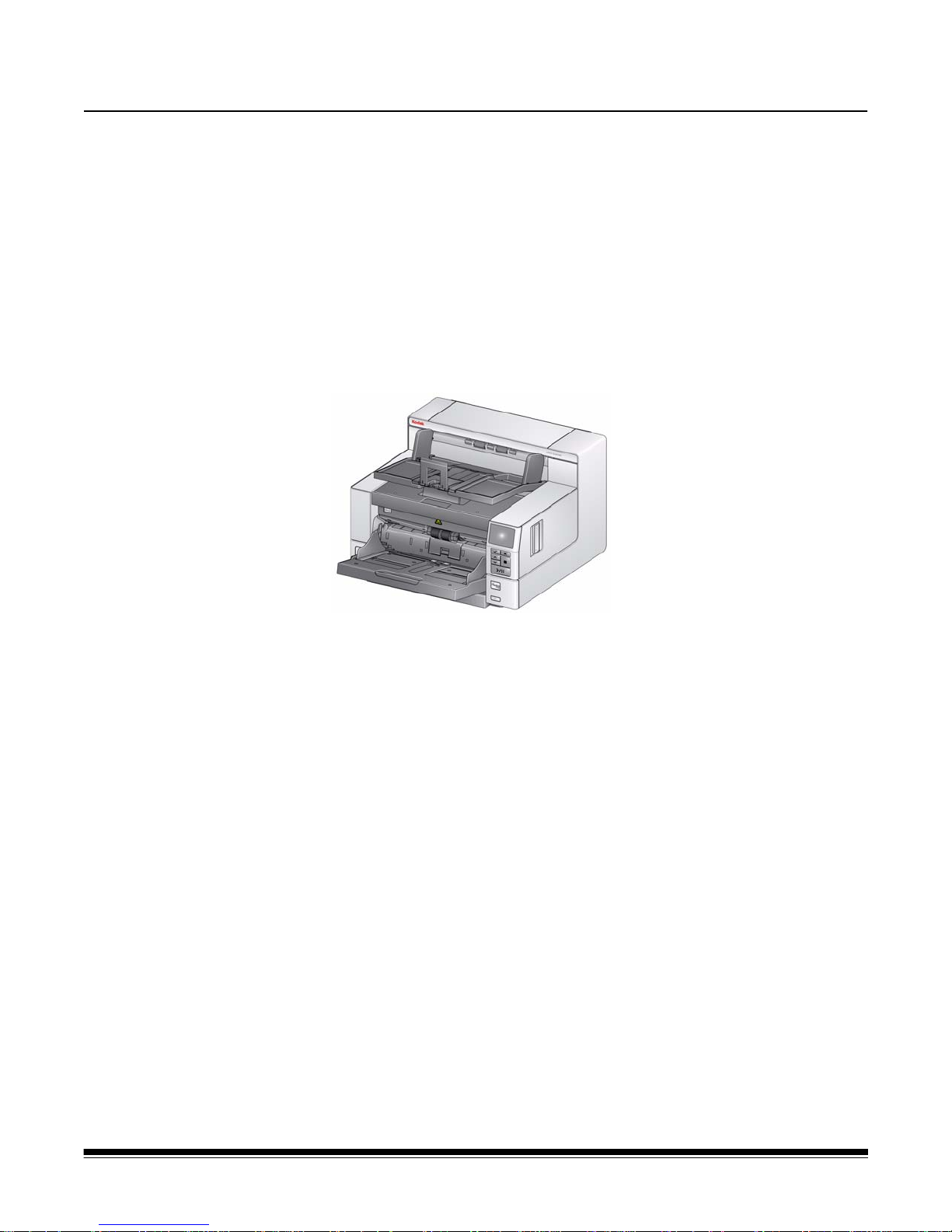
This User’s Guide provides information and procedures for using and
maintaining the Kodak i4250, i4650 and i4850 Scanners. The information in
this guide is for use with all models unless otherwise noted.
Kodak i4250 Scanner — desktop
duplex color scanner that scans up
to 110 pages per minute (200/300
dpi, black and white, grayscale and
color, landscape orientation)
lettersize documents.
Supporting
documentation
Kodak i4650 Scanner — desktop
duplex color scanner than scans up
to 130 pages per minute (200/300
dpi, black and white, grayscale and
color, landscape orientation)
lettersize documents.
Kodak i4850 Scanner — desktop duplex color scanner than scans up to 150
pages per minute (200/300 dpi, black and white, grayscale and color,
landscape orientation) lettersize documents.
In addition to this User’s Guide, the following documentation is also available:
• Installation Guide — provides a step-by-step procedure for installing the
scanner.
• Scanning Setup Guides — the TWAIN Datasource and ISIS Driver are
included with the Kodak i4250, i4650 and i4850 Scanner. Each Scanning
Setup Guide explains how to use basic image processing features. Both
guides are provided on the Installation CD in PDF format. You can also
download these guides from the website.
• Reference Guide — provides easy visual steps for cleaning your scanner.
Keep this guide close to the scanner so you can use it as an easy re ference.
A-61837 June 2015 1-1
Website: www.kodakalaris.com/go/docimaging

Accessories Kodak Enhanced Printer Accessory — the Kodak Enhanced Printer
Accessory provides an effective way to apply information to the scanned
document. It operates at full scanner speed. The printer can add a date, time,
document sequential counter and custom messages. All printer controls and
functions are accessible through the TWAIN Datasource or ISIS Driver.
Document Extenders — document extenders are available for scanning
documents longer than 43.2 cm (17 inches). These extenders are available in
66.04 cm, 76.2 cm and 86.36 cm (26- 30- and 34- inch ) leng th s.
Kodak Feeder Kit for Ultra-Lightweight Paper — allows you to feed
lightweight paper from a paper weight range of 25 g/m
(7 to 20 lbs). The Kodak Feeder Kit for Ultra-Lightweight Paper includes a feed
module and separation roller that are specially designed to feed light-weight
paper through the scanner transport.
Kodak A3 Flatbed Accessory — the Kodak A3 Flatbed adds scanning
capability for exception documents up to 11 x 17-inch (A3) size paper to your
Kodak i4250, i4650 or i4850 Scanner.
Kodak Legal Flatbed Accessory — the Kodak Legal Flatbed adds scanning
capability for exception documents up to: Legal / 8.5 x 14 in. / 216 x 356 mm.
2
to 80 g/m2 kg
What’s in the box Before you begin open the box and check the contents:
• Kodak i4250, i4650 or i4850 Scanner
• Output tray
• Three danglers for document stacking
• USB 3.0 cable
• AC power cord bundles
• Welcome Folio which includes:
- Installation CD
- Application CDs
- Warranty/Registration sheets
- Printed User’s Guide, English
- Printed Reference Guide
- Printed Installation Guide
- Miscellaneous flyers
1-2 A-61837 June 2015
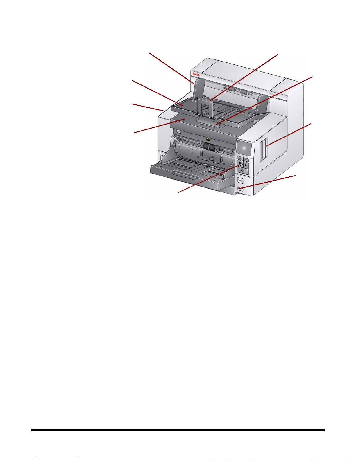
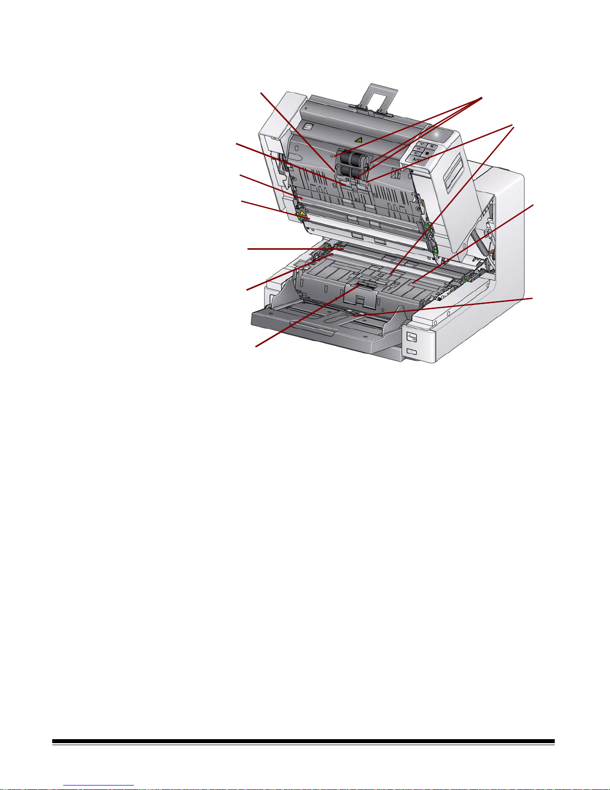
Scanner components
6
54
3
2
1
7
8
9
Front view
1 Printer access cover — lift this cover to access the feed module release
knob and the optional Enhanced Printer for changing printer positions
and maintenance. The scanner serial number and K number are also
located in this area.
2 Scanner cover — provides access to the internal components.
3 Output tray — collects the scanned documents.
4 Output tray side guides — can be moved in and out to accommodate
document size or folded flat on the output tray.
5 Document stop — aids in document stacking. You can slide this stop in
or out to accommodate the size of documents you are scanning or it can
be folded flat on the output tray.
6 Output tray height adjustment tab — this tab should be pulled out to
raise the front of the output tray when scanning for improved document
scanning. When the output tray is lifted, this tab automatically releases
and rests on the print access cover.
7 Scanner cover release latch — pull the lever forward to open the
scanner cover.
8 Power button — press to turn the scanner on or press and hold for one
second to turn the scanner off.
9 Operator Control Panel — allows you to view scanner status information
and use document handling features; the buttons on the Operator Control
Panel allow you to perform scanner actions. See the section entitled,
“Using the Operator Control Panel” in Chapter 3 for a description of each
these buttons.
A-61837 June 2015 1-3
.
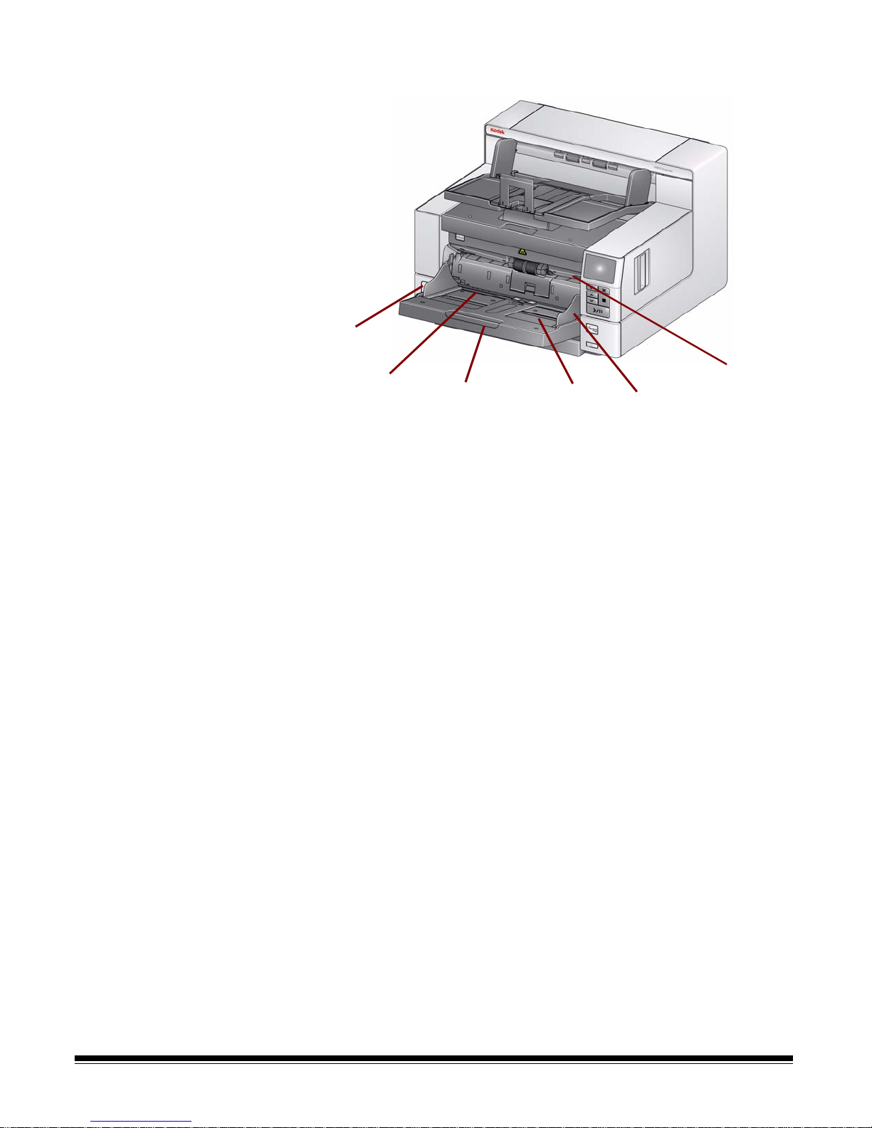
14
13
12
11
10
15
10 Gap release toggle switch — push in to adjust the space between the
feed module and separation roller for documents that require special
handling.
11 Print location indicators — these detent positions (at the edge of the
input elevator) make is easier to see where the print positioning will be on
the paper.
12 Input elevator extender — pull this extender out to accommodate
documents longer than 27.9 cm (11 inches).
13 Input elevator — holds up to 500 documents (20 lb / 80g/m
2
). The input
elevator can be set to accommodate stacks of 25-, 100-, 250- or 500documents. The input elevator can be folded up when it is not in use.
14 Input e levator side g uides — slide the guides in or o ut to accommodate
the document size you want to scan. Side guides can be left-, cente r- and
right-adjusted to accommodate documents of various widths. The side
guides can also be locked into position.
115 Feed module release lever — push this lever to the right to release the
feed module for cleaning or replacement. When using this release lever,
the scanner cover must be open.
1-4 A-61837 June 2015
Printer access view
1
2
3
4
1Printer cable — this cable connects directly to the printer carrier to allow
communication to the Enhanced Printer.
2 Enhanced Printer carrier/cartridge — allows front printing on
documents. This is only present if the Enhanced Printer Accessory is
installed.
3 Print positions — 8 print positions are available.
4 Feed module release knob — turn this knob to release the feed module
from it’s position for cleaning or replacing. Th e ar row on the r elease knob
should be pointing to the left when the feed module is engaged; and ri ght
when the feed module is disengaged.
A-61837 June 2015 1-5
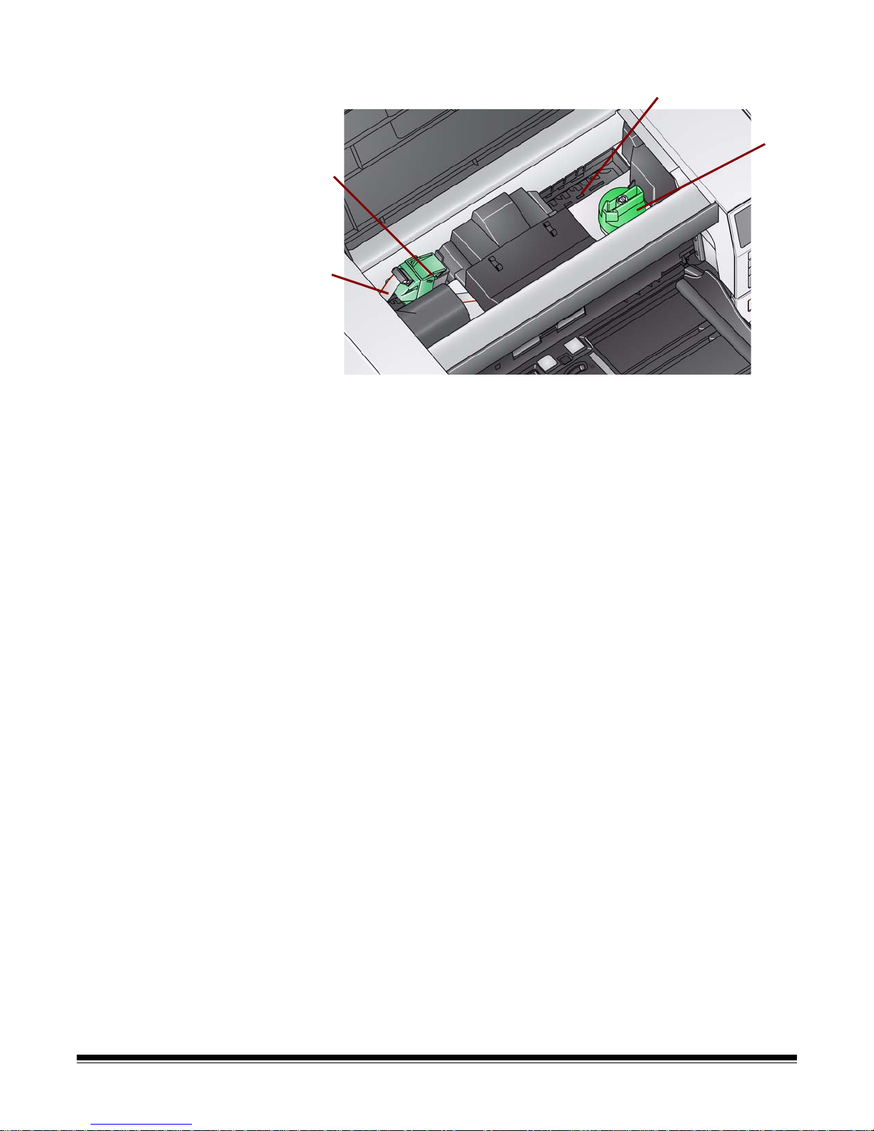
Inside view When you pull the scanner cover release latch fo rwa rd, the follo win g int er na l
1
2
2
4
5
7
8
3
9
6
3
components are visible.
1 Separation roller — provides smooth document feed in g an d separatio n
of various sizes, thicknesses and textures of documents.
2 Black/White background — this background can be changed to white or
black via your scanning application. Under normal scanning conditions,
you would use the black background. If you are scanning lightweight or
thin paper with printing on one side, you can use the white backg round to
help eliminate bleed-through in the final image. See the Scanning Setup
Guide - TWAIN Datasource/ISIS Driver for more information.
3 Imaging guides — keep imaging guides clean to obtain optimum image
quality.
4Rollers — provide smooth transport of documents through the scanner.
5 Feed module — provides smooth document feeding and separ ation of
various sizes, thicknesses and textures of documents.
6 Intelligent Document Protection Sensors — these sound sensors can
protect your documents from being damaged (e.g., the scanner will
detect the sound of a document being crunched as it enters the
transport).
7 Ink blotter channels and ink blotters — the ink blotters which are
placed in these channels, collect ink residue from the optional Enhanced
Printer Accessory.
8Sensors — these three ultrasonic se ns or s cover the width of the paper
path which aid in detecting multifed documents.
1-6 A-61837 June 2015
9 Paper present sensor — detects the presence of documents in the input
elevator. Documents must be covering this sensor in order for the
scanner to begin scanning.
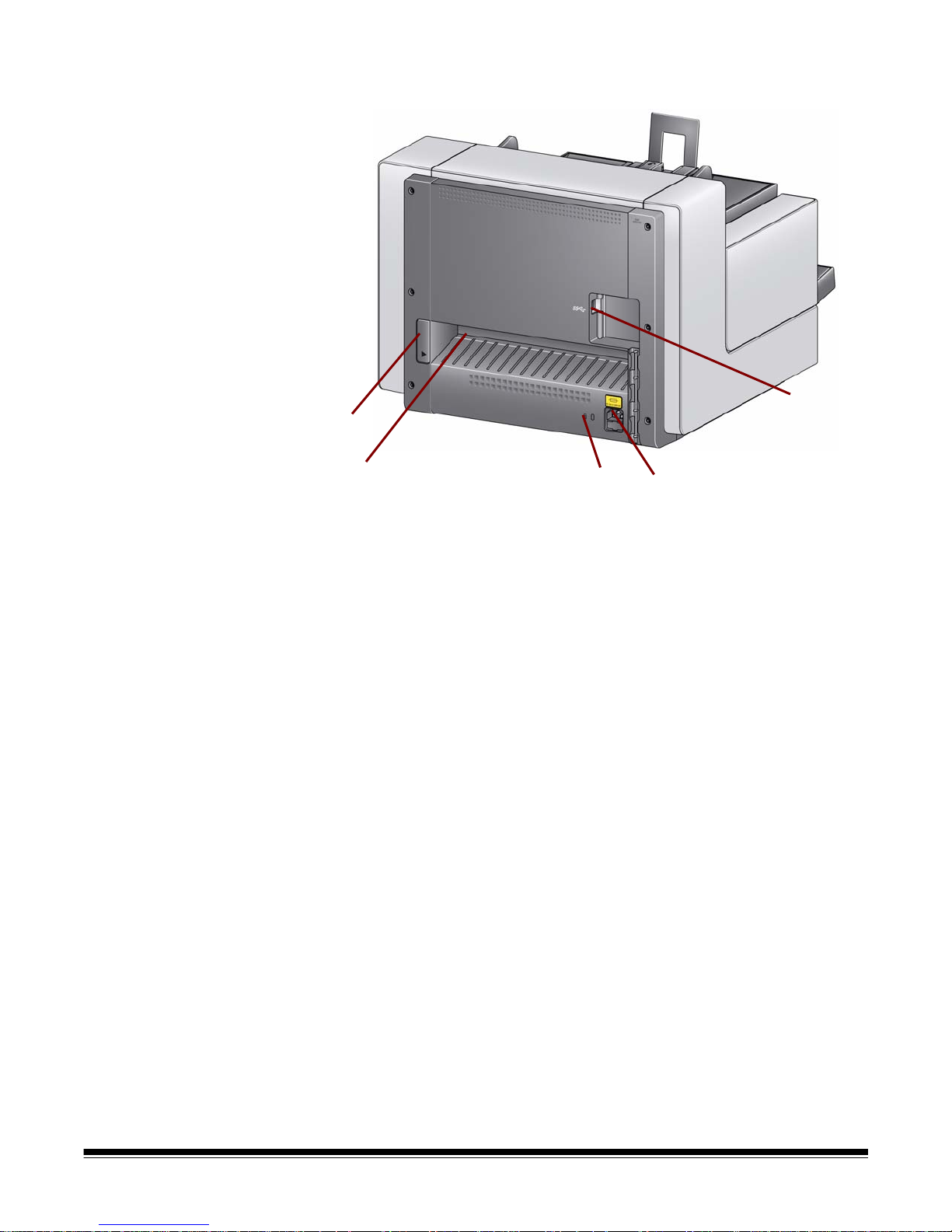
Rear view
4
3
2
1
5
1 Rear document exit — allows you to exit exception documents from the
rear of the scanner.
2 Rear document exit toggle — toggle this switch to enable the straight-
through paper path option of the scanner allowing exception documents
to be output through the rear document exit.
3 USB port — connects the scanner to the PC.
4 Power port — connects the power cord to the scanner.
5 Security lock port — connects a security lock to the scanner. You can
purchase a standard security lock at an office supply store. Refer to the
instructions provided with the security lock for installation procedures.
A-61837 June 2015 1-7

2 Installation
Contents Installing the scanner.................................................................................2-1
Installing the Driver Software.................................................................2-1
Attaching the output tray........................................................................2-2
Connecting the power cord and USB cable...........................................2-2
Turning the scanner on............................................ ... ... .... ... ... ..................2-3
Standalone mode...................................................................................2-4
Turning the scanner off............................................ ... ... .... ... .....................2-4
Power modes.............................................................................................2-5
Installing the scanner This section provides detailed information supporting the Installation Guide
that is provided with your scanner. Follow these steps in the order they are
provided to install your scanner.
NOTES:
• If you have already performed all of the steps in the Installation Guide, skip
this section.
Installing the Driver
Software - Windows
operating systems
• When positioning the scanne r, be sure to provide adequate clearance at the
back of the scanner if you will be using the rear document exit. For more
information on the rear document exit, see the section entitled, “Using the
rear document exit” in Chapter 3.
Do not install the USB cable before installing the Driver Software.
1. Insert the Kodak i4250, i4650 and i4850 Scanner Installation disk in the
disk drive. The installation program starts automatically.
NOTE: If the disk does not start automatically, open the My Computer
icon on your desktop. Double-click the icon indicating your disk
drive, then double-click on setup.exe.
2. Follow the prompts that are displayed until the installation is complete.
A-61837 June 2015 2-1
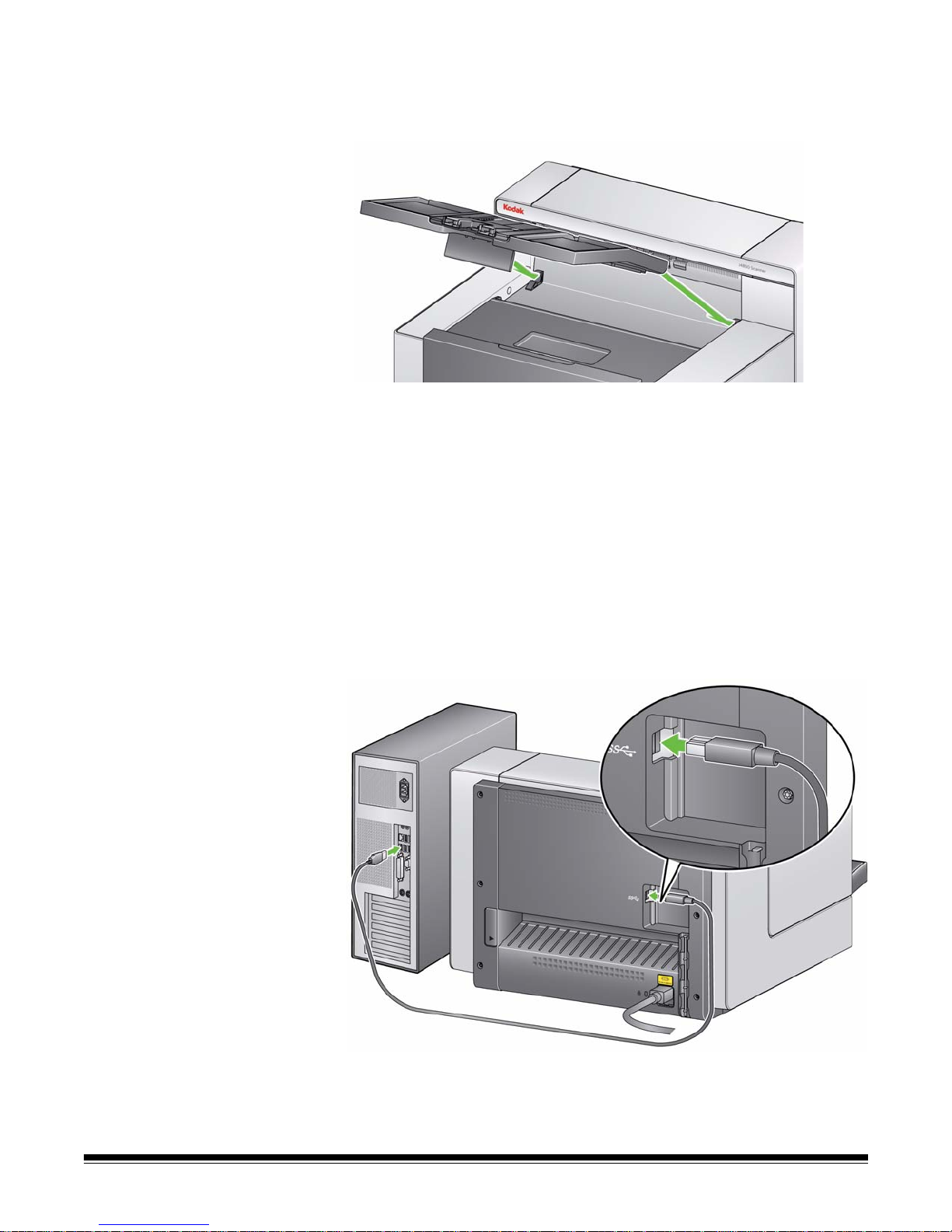
Attaching the output tray When you unpack the scanner, the output tray is packed in a separate box.
• Locate the output tray slots on the scanner, align the output tray with the
slots and set the output tray in place.
Connecting the power cord
and USB cable
When the drivers have been installed, connect the power cord and USB cable
to the scanner. Refer to the illustration below for making proper connections.
Make sure the power outlet is located within 1.52 meters (5 feet) of the
scanner and is easily accessible.
1. Select the appropriate AC power cord for your region from the supply of
power cords packed with your scanner.
2. Plug the output power cord into the power port on the scanner. Be sure it is
securely attached.
3. Plug the other end of the power cord into the wall outlet.
4. Attach the USB cable to the scanner USB port.
5. Attach the other end of the cable to the Super Speed “SS” port on your
computer. If this port not available, use any USB port.
2-2 A-61837 June 2015
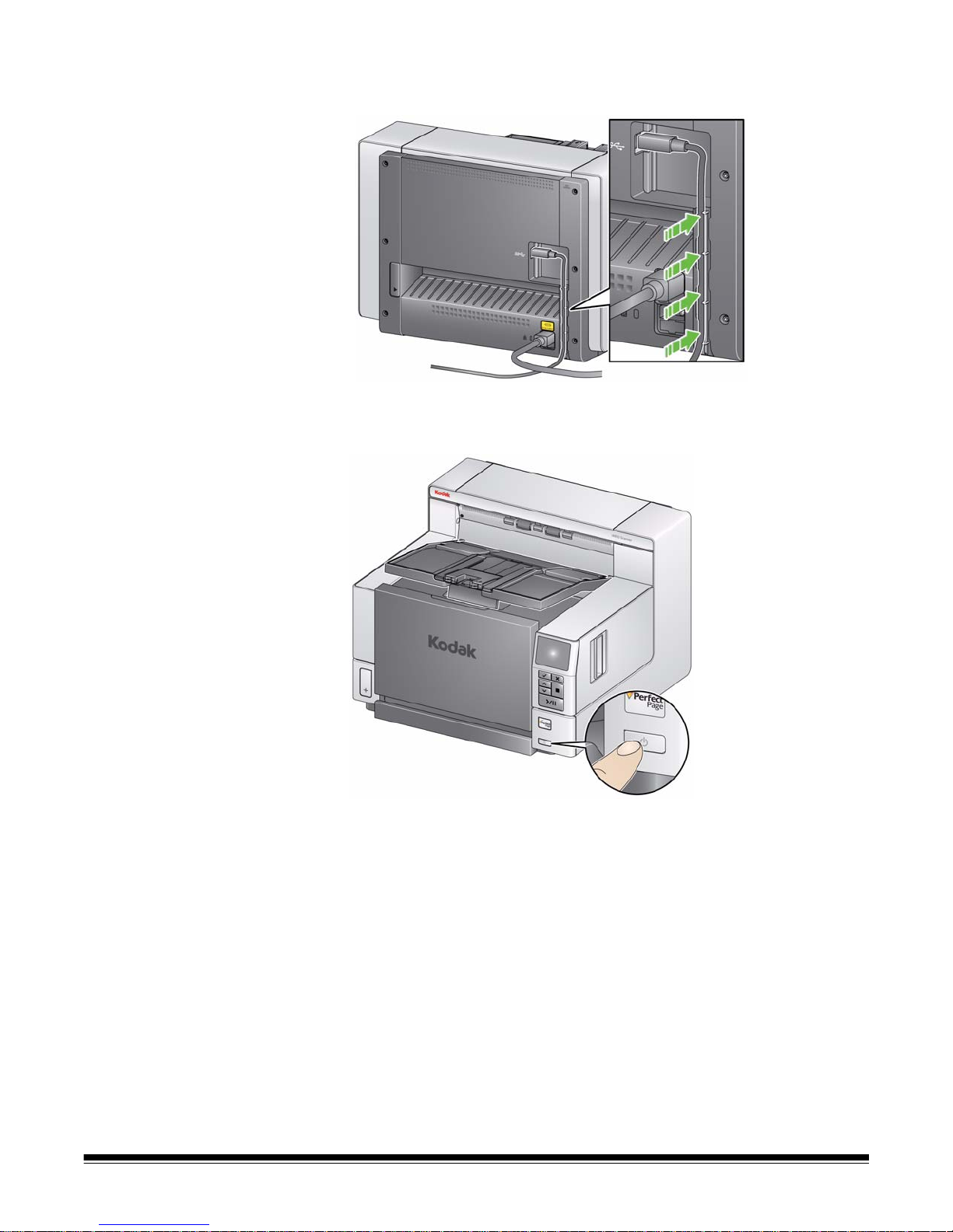
6. Secure the USB cable into the cable routing channel on the back of the
scanner.
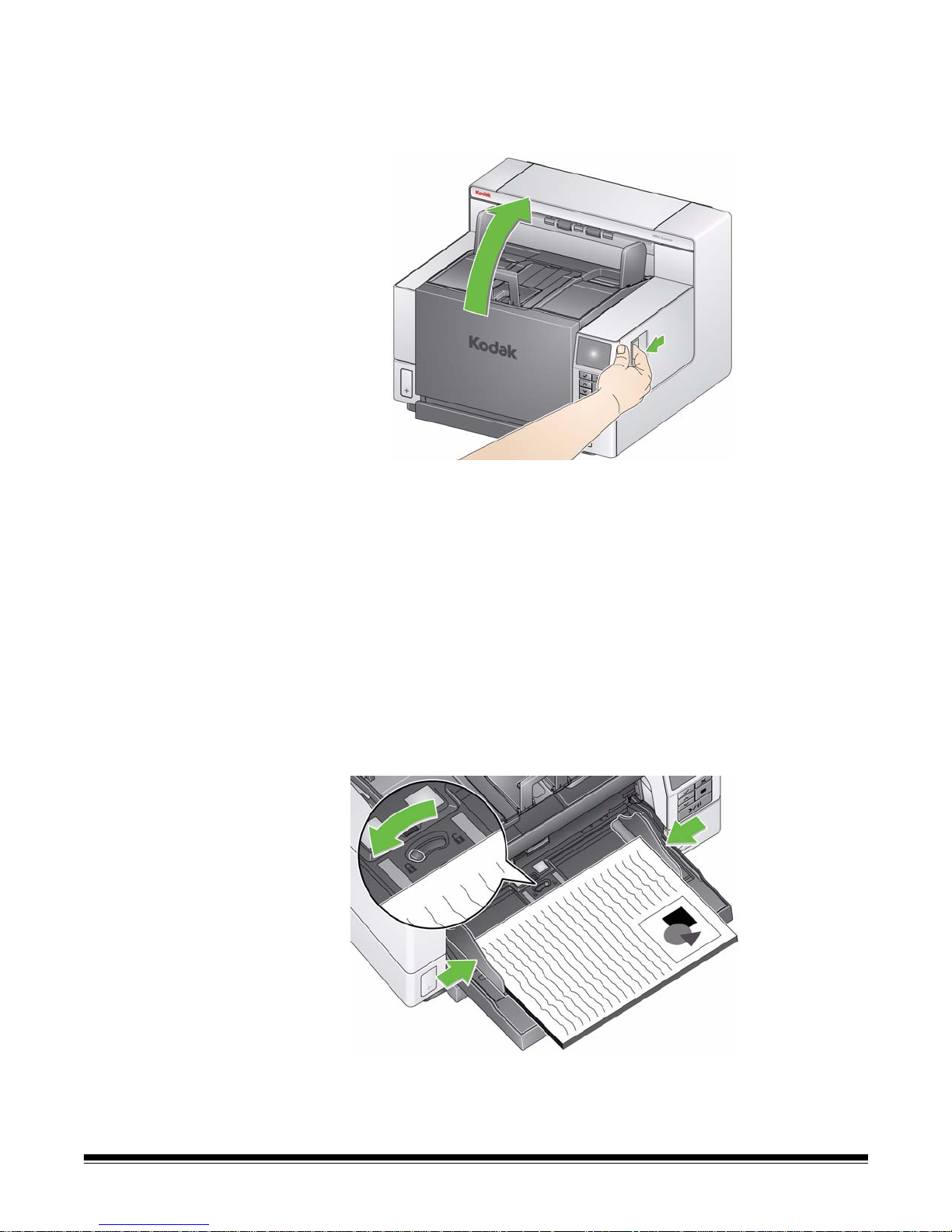
Turning the scanner
on
• Press the Power button.
When you turn on the scanner, the input elevator will open if it is not already
opened and the green indicator on the St art/Pause button will flash as the
scanner goes through a series of self tests.
A-61837 June 2015 2-3
The scanner takes less than 20 seconds to complete the power-up sequence
and be ready to scan. When the installation process is complete and ready to
scan, the green LED on the Start/Pause button will stop flashing and remain
constant and the Ready screen will be displayed.
Standalone mode The i4x50 Scanners can be used in standalon e mode and can be powered on
without connecting to a host PC. When the scanner is in standalone mode, the
following functions are available in Diagnostics mode:
• Count only
• Count only with multi-feed
• UDDS calibration
Turning the scanner
off
•Print test
• Patch test
• Press the Power button for one second.
• If the scanner has a critical error, you can press and hold the Power button
for 5 seconds to turn the scanner off.
2-4 A-61837 June 2015
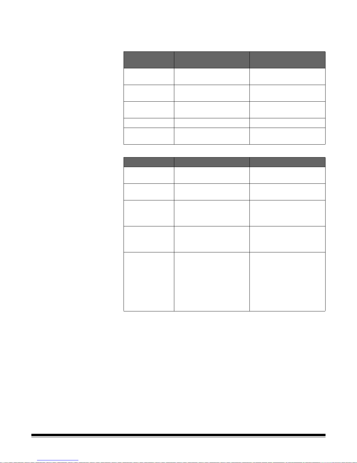
Power modes The following chart provides information regarding the power modes of the
scanner, LED status and the manual or automatic action that will put the
scanner into a given power mode.
Mode Operator Control Panel
LED
Standby
(Off)
Sleep
(Low Power)
Ready
(Not Scanning)
Scanning On (green) < 130 watts
Ready
(No Host)
Mode Transition Manual Action Automatic Action
Standby to
Ready
Ready to
Standby
Ready to Sleep None
Sleep to Standby
Sleep to Ready
once every 2.5 seconds
Tap the Power button None
Press and hold the Power
button for 1 second
Press and hold the Power
button for 1 second
Any of the following:
• Tap the Power button
• Tap any Operator Control
Panel button
• Place paper in the input
elevator
• Receiving a host
command
Off < 0.5 watt
Flashing green
On (green) < 55 watts
On (red) < 55 watts
Power Consumption
< 1.5 watts
None
Programmable time delay:
1 to 240 seconds
Factory default: 15 minutes
Programmable time delay:
0 to 240 seconds
Factory default: 60 minutes*
None
A-61837 June 2015 2-5
* Consult with Kodak Alaris Service personnel for custom options.

3Scanning
Contents Getting your scanner ready to scan...........................................................3-1
Adjusting the input elevator....................................................................3-2
Installing the document extender ...........................................................3-4
Adjusting the output tray or rear edge alignment or improved or best
document handling............... ... ... ... .... ...................................... ... .... ... .....3-4
Adjusting the output tray for lead edge alignment and normal document
handling..................................................................................................3-6
Using the rear document exit .................................................................3-6
Getting your documents ready to scan ......................................................3-7
Scanning documents......................................... .... .....................................3-8
Starting, stopping and pausing the scanner...........................................3-8
Quick clean using the Start/Pause button..............................................3-8
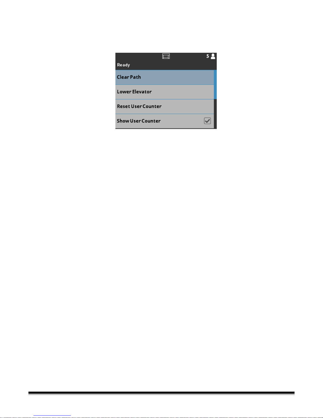
Using the Operator Control Panel..............................................................3-9
Ready screen.................................... ... ... ... ... .... ... ................................3-10
Status area.............................................. ... .... ... ... ... .... ......................3-10
Displaying the Operator Log.............................................................3-12
Displaying scanner Information ........................................................3-12
Diagnostics.......................................................................................3-13
Settings screen ....................................................................................3-19
User Counter ....................................................................................3-19
Automatic elevator............................................................................3-20
Changing the volume................................. .... ... ... ... .... ... ...... ... .... ... ...3-20
Application Overrides........................................................................3-21
Selecting your scanning application ........................................................3-27
Getting your scanner
ready to scan
A-61837 June 2015 3-1
1. Be sure the scanner is on and ready to scan (Start/Pause button LED is
green and constant).
2. Adjust the input elevator to meet your scanning needs. See the section
entitled, “Adjusting the input elevator” for more information.
3. Adjust the output tray to meet your scanning need s. See the s ec tio n
entitled, “Adjusting the output tray” for more information.
4. Select your scanning application.
Adjusting the input
elevator
You can adjust the side guides and input elevator height to accommodate your
scanning needs. When the scanner is not in use, the input elevator can be
folded up against the scanner.
NOTE: The input elevator must be in the lowest position before closing it.
• Adjusting the side guides — the side guides can be adjusted for right-
edge, left-edge or center feeding. The side guides can b e moved together
for center feeding or independently for offset feeding (right-edge or left-
edge). Before moving the side guides, be sure th e lo ck ing switch is not in
the locked position (see below).
NOTE: When using the optional Enhanced Printer, documents should be
placed in the input elevator in a manner that will align the print
string in the proper location. Offset feeding may be required.
• Locking the side guides — side guides may be locked into position after
they are adjusted. This may be helpful when the placement of a print string
is important.
To lock the side guides remove any documents from the input elevator and
move the lock switch to the left (the locked position).
3-2 A-61837 June 2015
• Adjusting the height of the input elevat or — the input elevato r can be set
to accommodate stacks of 25-, 100-, 250- or 500-documents of
2
20 lb. /80 g/m
bond paper. Input elevator settings are typically made
through your scanning application software (e.g ., TWAIN Dat asource or ISIS
Driver).
The input elevator setting can be overridden by using the Oper ator Control
Panel. For more information see the section entitled, “Application
Overrides” later in this chapter.
When the input elevator is set to the Document Feeder position, the input
elevator will remain in the highest position. When set to 100, 250 or 500,
the input elevator will automatically raise to feed documents and lower
after the last document in your stack has been fed.
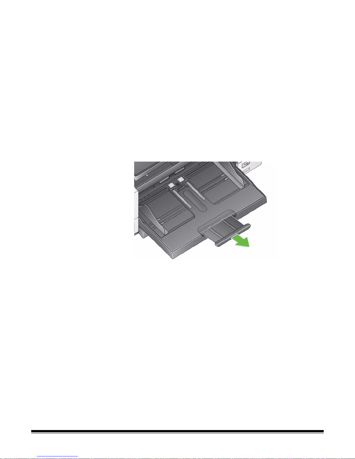
• Adjusting the input elevator
- Document lengths up to 27.9 cm (11 inches) — no adjustments are
required.
- Document lengths from 27.9 to 43.2 cm (11 to 17 inches) — pull out
the document extender.
- Documents lengths more than 43.2 cm (17 inches) — if you are
scanning documents longer than 43.2 cm (17 inches), the scanner driver
must be set to accommodate these long docume nts. Be sure to verify that
the Maximum Length option on the Device-General t ab (TWAIN
Datasource) or the Longest Document option on the Scanner tab (ISIS
Driver) is set to longer than the longest document being scanned.
NOTES:
• Operator assistance may be required for scanning documents greater
than 43.2 cm (17 inches).
• It is recommended that you use a document extender if you are
scanning documents longer than 43.2 cm (17 inches). Three sizes of
document extenders are available for scanning documents from
43.2 cm (17 inches) to 86.36 cm (34 inches). See the section entitled,
“Supplies and Consumables” in Chapter 5.
• Document weights — the maximum document weight for the input
elevator is the approximate weight of an A3 (11 x 17-inch) 500-sheet
ream of paper. If you are scanning documents larger than A3
(11 x 17-inch), the recommended weight capacity should not exceed
4.5 kg (10 pounds). If the documents you ar e scanning are larger than A3
(11 x 17-inch), scan less than 100 sheets at a time.
A-61837 June 2015 3-3
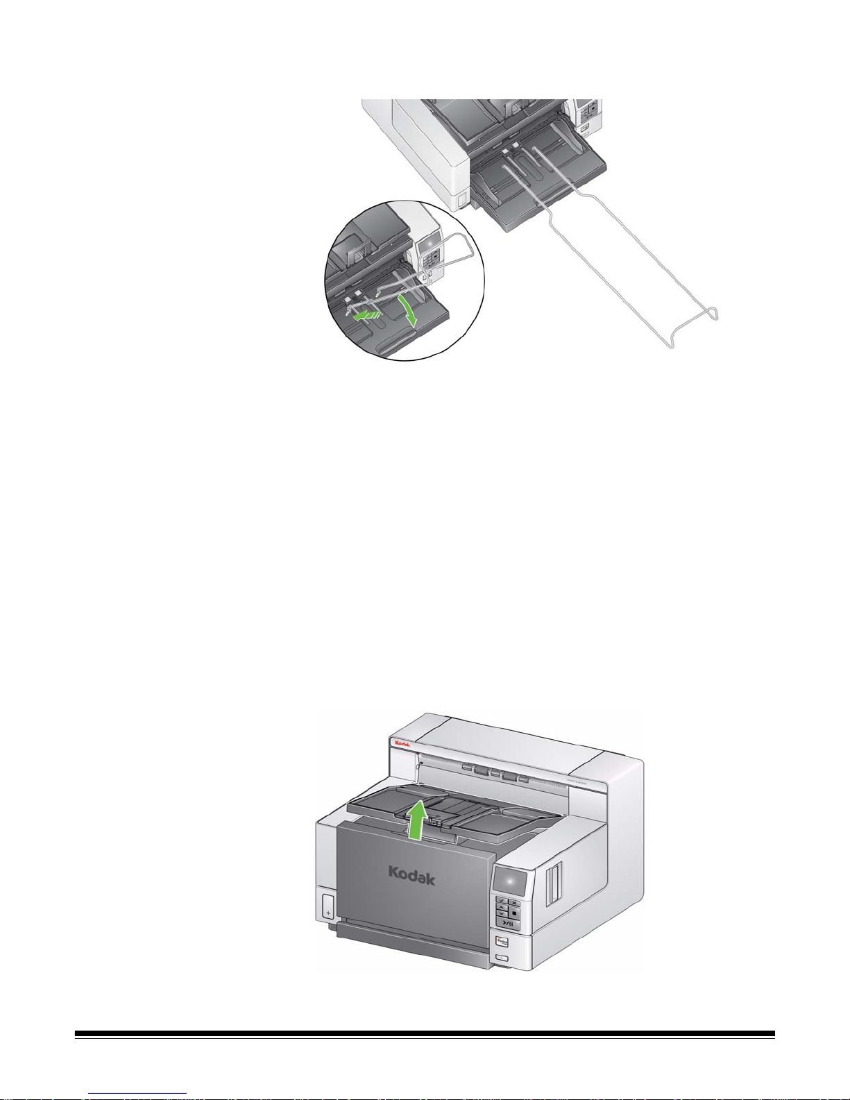
Installing the document
extender
• Insert the ends o f the document extender into the holes on the in put elevator
or the output tray and lower the extender into position.
Adjusting the output tray
for rear edge alignment or
improved or best document
handling
The Kodak i4250, i4650 and i4850 Scanners are designed with improved
stacking performance which allows most users to scan documents without the
assistance of the output tray side guides and document stop. With one or bo th
side guides down and the height adjustment tab raised, you can quickly and
easily remove the scanned documents from the front-, right- or left-side of the
scanner. Try using this method before using the side guides and document
stop with Improved or Best Document Handling enabled in the scanning
application or through the Operator Control Panel using the Application
Overrides function.
NOTE: If you find it more convenient to use the side guides and document
stop, see the next section for adjustment procedures.
• Adjusting the angle of the output tray — it is strongly recommended that
you scan documents with the Improved or Best Document Handling
option enabled in the scanning application along with the angle of the output
tray in the “up” position to achieve best stacking performance. Just lift the
front of the output tray and the height adjustment tab will release from
underneath the output tray.
3-4 A-61837 June 2015
To lower the output tray, gently push the height adjustment tab underneath
the output tray while lowering the output tray on the printer access cover.
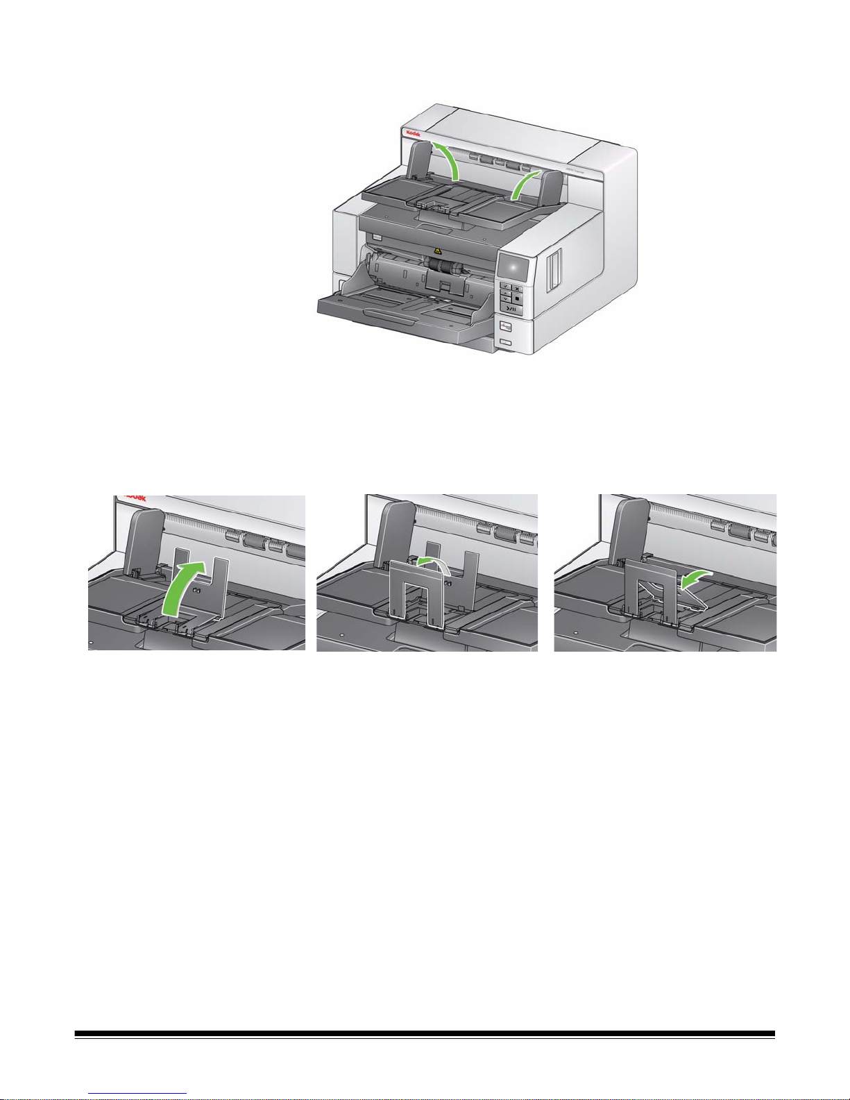
• Adjusting the side guides — open and adjust the side guides on the
output tray to match the position of the side guides on the input elevator.
The side guides can also be folded flat against the output tray.
• Adjusting the document stop — adjust the output tray document stop to
slightly longer than the longest document being fed. If you are scanning
documents longer than the output tray will accommodate, fold the document
stop flat on the output tray.
A-61837 June 2015 3-5
Adjusting the output tray
for lead edge alignment
and normal document
handling
The Kodak Lead Edge Alignment Exit Tray Accessory is available if you want
the edges of your documents to align against the output tray document stop
after scanning. For more information about using this exit tray, see the
instructions that came with this accessory.
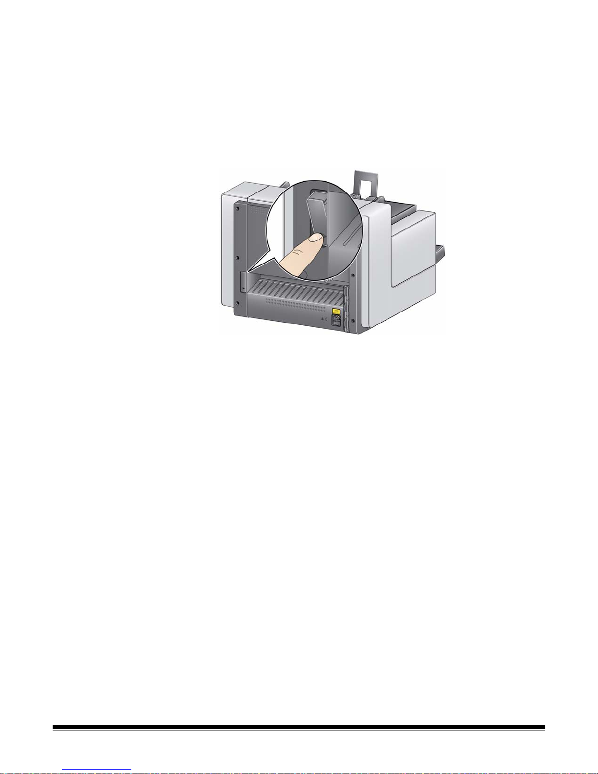
Using the rear document
exit
Documents that require special handling (e.g., fragile documents, shipping
envelopes, etc.) can be output using the rear document exit. This exit provides
the straight-through paper p ath option that a llows an exception document(s) to
pass straight through the transport, thus reducing the possibility of a document
jam.
Use the rear document exit when:
• documents are too stiff (e.g., rigid) to make the turn in the transport and are
jamming.
• documents are fragile and you do not want to bend them.
• output sta cking order is not important.
• scanning directly into the recycle bin when documents are no longer needed
after scanning.
• scanning photographs.
NOTES:
• Be sure to toggle the rear document exit switch back into it’ s original position
when finished.
• Be sure that you have adequate clearance behind the scanner to feed the
document(s) through when using this option.
• When scanning several documents through the rear document exit, the
documents will be output in the reverse scanning order.
3-6 A-61837 June 2015

Getting your
documents ready to
scan
1. Standard paper size documents feed easily through the scanner. When
organizing your documents for scanning, stack the documents so the lead
edges are aligned and centered in the input elevator. This allows the
feeder to introduce documents into the scanner one at a time.
2. Remove all staples and paper clips before scanning. Staples and paper
clips on documents may damage the scanner and documents.
3. All inks and correction fluids on the paper must be dry before scanning is
started.
4. Torn, damaged or crushed pages can be transported successfully through
the scanner. However, no scanner can transport every possible type of
damaged paper. If in doubt about whether a specific damaged document
can be transported through the scanner, place the document in a clear
protective sleeve and use the rear document exit. Sleeves should be
manually fed, one at a time, folded edge first, using the gap release toggle
switch.
NOTE: The optional Kodak A3 Flatbed Accessory or the Kodak Legal
Flatbed Accessory can also be used for scanning fragile
documents.
5. Place the documents you want to scan in the input elevator.
NOTES:
• Some very thick and/or stiff documents; such as shipping envelopes, may
require the following:
- Use of the rear document exit.
- Use of the gap release toggle switch.
- Removal of the pre-separation pad.
- Scanning at 300 dpi or more to reduce the scanner transport speed.
A-61837 June 2015 3-7

Scanning documents The scanner must be enabled to scan documents. This is done through the
scanning application. After enabling the scanner, depending on how your
scanner is configured, your scanner will either automatically start scanning
(i.e., auto start), or will start scanning when you press the Start/Pause button
on the Operator Control Panel. For more information, see the documentation
that supports your scanning application.
1. After you prepare your documents according to the guidelines in the
previous section, be sure your scan job is set up in your scanning
application as desired.
2. Place the documents you want to scan in the input elevator.
3. Start scanning via your scanning application.
Starting, stopping and
pausing the scanner
Quick clean using the Start/
Pause button
You can manually start, stop or pause the scanner while scanning documents.
• To temporarily pause scanning, press the Start/Pause button on the
Operator Control Panel once.
• Press the Start/Pause on the Operator Control Panel to restart scanning
after it has been paused.
• If you want to stop scanning, press Stop on the Operator Control Panel.
NOTE: During scanning the scanner monitors its own internal image buffer
memory. In order to prevent overwriting images before the host
computer can retrieve them, the scanner will automatically pause the
feeder and will resume scanning when enough internal buffer memory
is free.
When the scanner is in the paused state, the scanner cover can be opened
without disabling the scanner. If you notice streaks on your images while
scanning, you can press the Start/Pause button to quickly clean the imaging
guides in the middle of scanning a batch of documen ts. To do this:
• Press the Start/Pause button, open the scanner cover, clean the imaging
guides, close the scanner cover and press the St art/Pause button. See the
section entitled, “Cleaning the imaging guides - basic” in Chapter 5 for
procedures.
3-8 A-61837 June 2015
 Loading...