

Page 1

Color Management Options
The Kodak Professional 8660 thermal printer (8660 pr inter) produces
accurate and consistent color. Since the 8660 printer produces such
accurate and consistent color, you may not need to use the printer’s color
management feature. However, if you wish to use color management, the
CD that is shipped with the printer includes Kodak Professional Colorflow
ICC color connector software (color connector) that you can install on
your host computer.
Operator’s Guide
Printing Guide
Color Management
Calibration
Color Connector
When you use Adobe Photoshop, the colors you see on your monitor may
appear differently from the colors in the output from your printer. In
addition, both may appear differently from your original image. White
clouds in a scanned photograph may appear yellow on your computer
monitor and change to a greenish tint on your printed copy.
This inconsistency occurs because the methods used to reproduce color
vary significantly. Monitors and scanners represent colors as a
combination of red, green, and blue (RGB), while printers produce color
by using various combinations of cyan, magenta, yellow, and black
(CMYK). Input and output devices are also limited by the range of colors
they can produce.
CONTENTS
INDEX
SEARCH
HELP
Network
Interface Guide
Color Management
Options
Using Color
Connector
Menus and Dialog
Boxes
Page 2

Color connector is a stand-alone application that allows you to make
prints that match the colors produced by an input device such as a
scanner or monitor. It also allows you to simulate a job as if it were
printed on a commercial printing press.
You do this by combining transforms to create documents which contain
color management information specific to the input device you are using
such as a scanner, digital camera, or your monitor, and your output device
such as the 8660 printer.
Creating Color Connector Files
Operator’s Guide
Printing Guide
Color Management
Calibration
You create color connector files by extracting source transforms,
simulation transforms, and destination transforms from ICC profiles.
These transforms are represented as “puzzle pieces.” Drag each selected
puzzle piece to an empty socket in the color connector template for your
job. Each type of transform is represented by a particular shape. Match
the shape of the transform with the shape of the socket in the template.
With color connector you can color manage multiple source images on a
single page. The template contains six sockets to allow separate color
management for the six different kinds of source images.
The color connector file you create can be applied to your print job or
stored in the printer as a default.
er to Using Color Connector for complete instructions on how to use
Ref
this color management software.
CONTENTS
INDEX
SEARCH
HELP
Network
Interface Guide
Color Management
Options
Using Color
Connector
Menus and Dialog
Boxes
Page 3

Using Color Connector
This section describes how to use the Kodak Professional Colorflow ICC
color connector (color connector) as an assembly tool to create color
connector files.
Operator’s Guide
Printing Guide
IMPORTANT: The dialog boxes in this section show color connector
software used with other Kodak Professional thermal
printers that use different ribbon and media combinations.
The dialog boxes for color connector software used with the
8660 printer look similar and have identical functionality.
System Requirements
Listed below are the hardware and software necessary to run color
connector.
Macintosh Systems
•
60 MHz PowerPC or higher processor with a minimum of 16 MB of
memory. (A 150 MHz PowerPC 604e processor with 32 MB of memory
is recommended.)
•
Macintosh operating system 7.6.1 or higher operating system.
(Macintosh operating system 8.0 is recommended.)
•
a monitor with a minimum spatial resolution of 640 x 480 pixels.
•
a video system with a minimum resolution of 256 colors.
Color Management
Calibration
Network
Interface Guide
Color Management
Options
Using Color
Connector
Menus and Dialog
Boxes
CONTENTS
INDEX
SEARCH
HELP
Page 4

Windows Systems
•
60 MHz Pentium processor with a minimum of 16 MB of memory. (A 100
MHz Pentium processor with 32 MB of memory is recommended.)
•
Windows 95/98, Windows NT 4.0/5.0
•
a monitor with a minimum spatial resolution of 640 x 480 pixels
standard VGA).
•
a video system with a minimum color resolution of 256 colors.
Operator’s Guide
Printing Guide
Color Management
Calibration
ICC Profiles
The color management information you need to create color connector
files is contained in the ICC Profiles. The profiles, an industry standard
format for color management, are defined by the International Color
Consortium. They contain multiple pieces of color information for input,
output, and display devices. This information is individually extracted from
the profiles and appears as puzzle pieces in the Transforms list box in the
color connector window.
ICC profiles are included on the software CD that came with your printer.
The profiles for the 8660 printer for each media combination are installed
automatically with the color connector application. Other common ICC
profiles are also included on the CD. Copy the profiles you wish to use to
the folder containing the profiles that were installed with the color
connector application. See the readme file for color connector for a listing
of the ICC Profiles included on the CD.
CONTENTS
INDEX
SEARCH
HELP
Network
Interface Guide
Color Management
Options
Using Color
Connector
Menus and Dialog
Boxes
Page 5
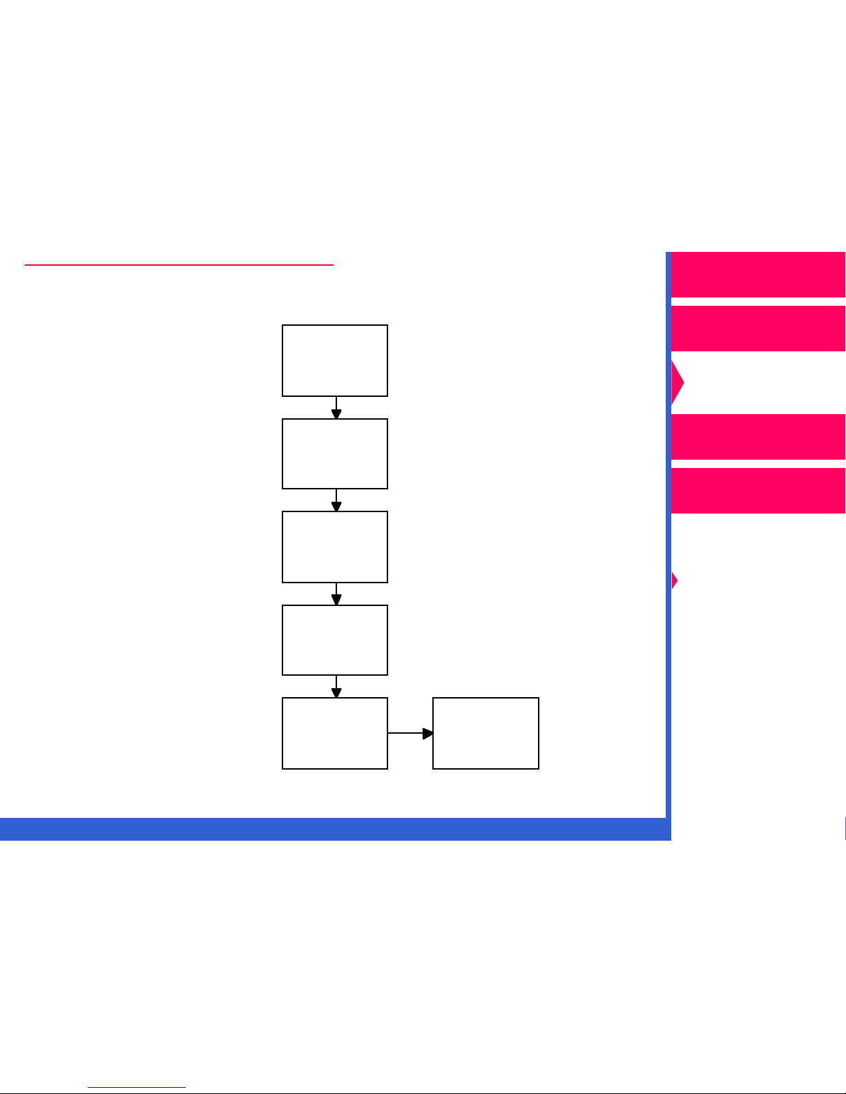
Steps to Create Color Connector Files
Run color
Step 1
connector
application
Operator’s Guide
Printing Guide
Color Management
CONTENTS
Step 2
Step 3
Step 4
Step 5
INDEX
Select and
drag
transforms to
template
Select desired
color connector
options
Save the color
connector file
Send color
connector file
to printer as
a default
or
Print using color
connector file
SEARCH
Calibration
Network
Interface Guide
Color Management
Options
Using Color
Connector
Menus and Dialog
Boxes
HELP
Page 6
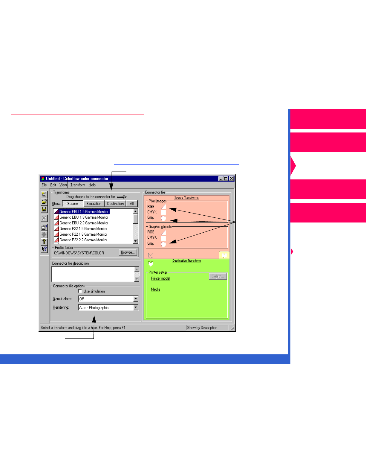
Color Connector Window
When you access the color connector application, the color connector
window appears. From this window you can create your color connector
files. For descriptions of the menu items and dialog boxes used in the
color connector application, ref
er to “Menus and Dialog Boxes.”
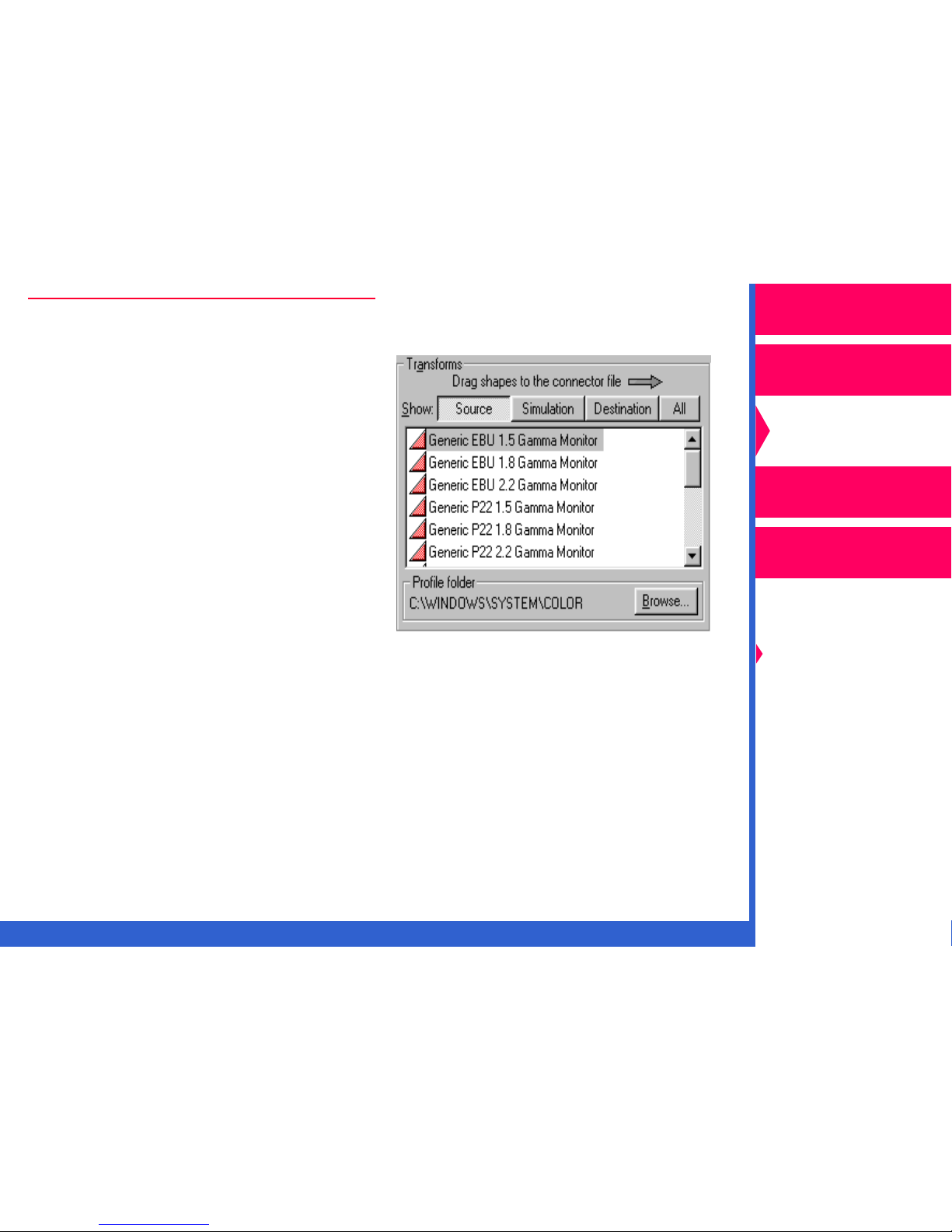
Transforms List
Template
Sockets
Operator’s Guide
Printing Guide
Color Management
Calibration
Network
Interface Guide
Color Management
Options
Using Color
Connector
Menus and Dialog
Boxes
Options
CONTENTS
INDEX
SEARCH
HELP
Page 7

Getting Ready to Use Color Connector
The following steps describe how to get started with color connector.
NOTE: The illustrations in this section show Windows dialog boxes. The
dialog boxes for Macintosh are similar and have identical
functionality.
1.
Install the software for color connector and the printing software
including the export module. The software is included on the CD that
came with your printer.
Operator’s Guide
Printing Guide
Color Management
Calibration
2.
Put any additional ICC Profiles in the folder containing your ICC
Profiles that were shipped with the printer. The default folder for the
ICC Profiles is:
•
for Windows systems, Windows\System\Color.
•
for Macintosh systems:
TM
–
if you are using ColorSync
2.1, System
Folder:Preferences:ColorSyncTM Profiles.
–
if you are using ColorSyncTM 2.5, System Folder:ColorSync
Profiles.
NOTE: Before you use color connector for the first time, you may wish to
complete the tutorial that is included on the CD.
3.
Start the color connector application.
CONTENTS
INDEX
SEARCH
HELP
Network
Interface Guide
Color Management
Options
Using Color
Connector
Menus and Dialog
Boxes
Page 8
The color connector window appears.
Operator’s Guide
Printing Guide
Color Management
Calibration
Network
Interface Guide
Color Management
Options
Using Color
Connector
Menus and Dialog
Boxes
CONTENTS
INDEX
SEARCH
HELP
Page 9
4.
Pull down the File menu, and select “Preferences”.
5.
Click on
Browse (Select
in
Macintosh) in the Printer
export modules folder
portion of the Preferences
dialog box. A file selection
dialog box appears.
6.
Locate the Plug-ins
(Printing) folder, and
select the export module
for the 8660 printer.
Operator’s Guide
Printing Guide
Color Management
Calibration
Network
Interface Guide
Color Management
Options
NOTE: For descriptions of the options in the Default settings for new
connector files box, ref
er to “Menus and Dialog Boxes.”
Follow the procedures on the following screens to build your own color
connector files.
CONTENTS
INDEX
SEARCH
HELP
Using Color
Connector
Menus and Dialog
Boxes
Page 10
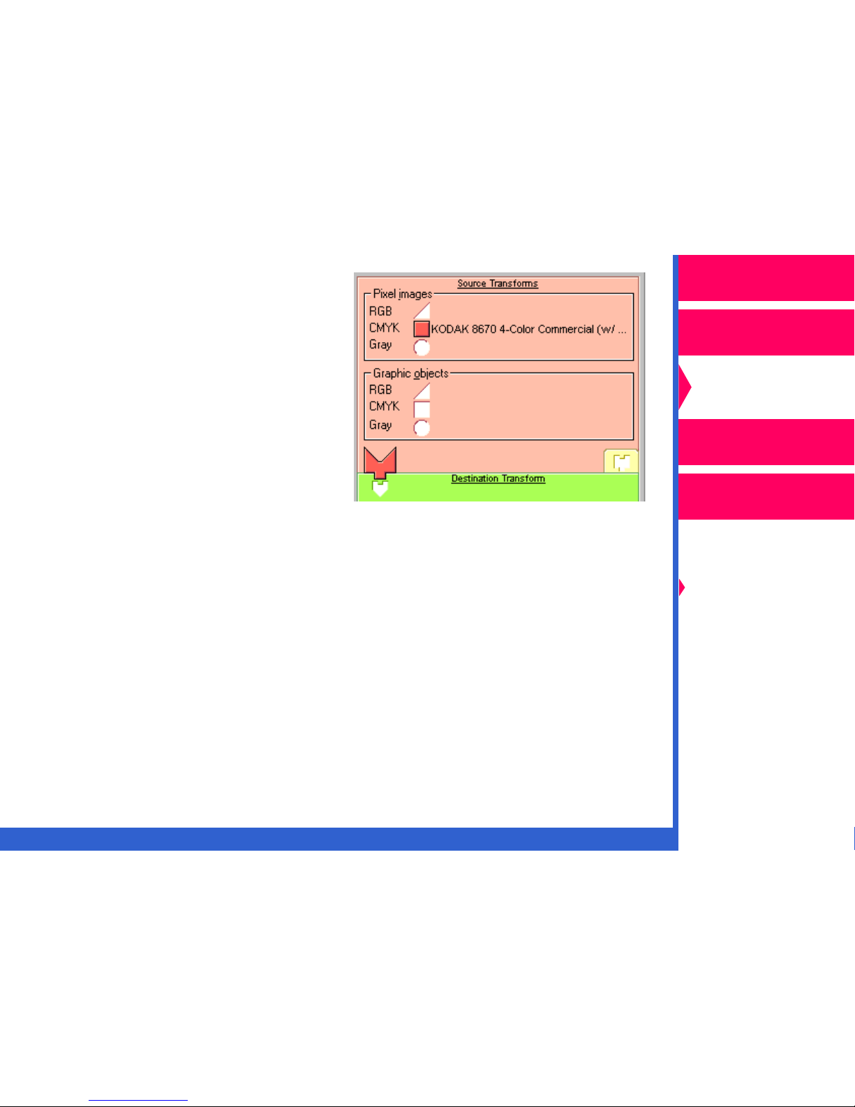
Creating a Color Connector File
1.
Select puzzle pieces from the
list of transforms (on the left
side of the color connector
window) that represent the
sources of color data.
Operator’s Guide
Printing Guide
Color Management
The puzzle pieces are extracted
from the ICC Profiles. Drag the
pieces to the appropriate
Source Transforms sockets in
the template on the right side of
the color connector window.
The template has six sockets for source transforms. You can apply
independent color management to up to six different kinds of sources
in one job:
•
RGB, CMY, and grayscale pixel images such as TIFF files or
scanned photographs.
•
RGB, CMY, and grayscale graphic images such as EPS files or text.
IMPORTANT: If your file contains a source that uses PANTONE® Color,
leave the socket empty for that color space.
Calibration
Network
Interface Guide
Color Management
Options
Using Color
Connector
Menus and Dialog
Boxes
CONTENTS
INDEX
SEARCH
HELP
Page 11
After you drag the first source
transform to the template, the
source puzzle piece appears in
its socket indicating that the
minimum requirement for source
transforms is complete.
Operator’s Guide
Printing Guide
Color Management
Calibration
Network
Interface Guide
NOTE: If you wish to change the transform you placed in the socket:
•
select a new transform; and drag it to the socket. It replaces the
previously-selected transform.
To delete a transform from a color connector socket:
•
select the transform.
•
pull down the Transforms menu, and select “Delete Transform”
on Windows systems or “Clear Transform” on Macintosh
systems.
CONTENTS
INDEX
SEARCH
HELP
Color Management
Options
Using Color
Connector
Menus and Dialog
Boxes
Page 12
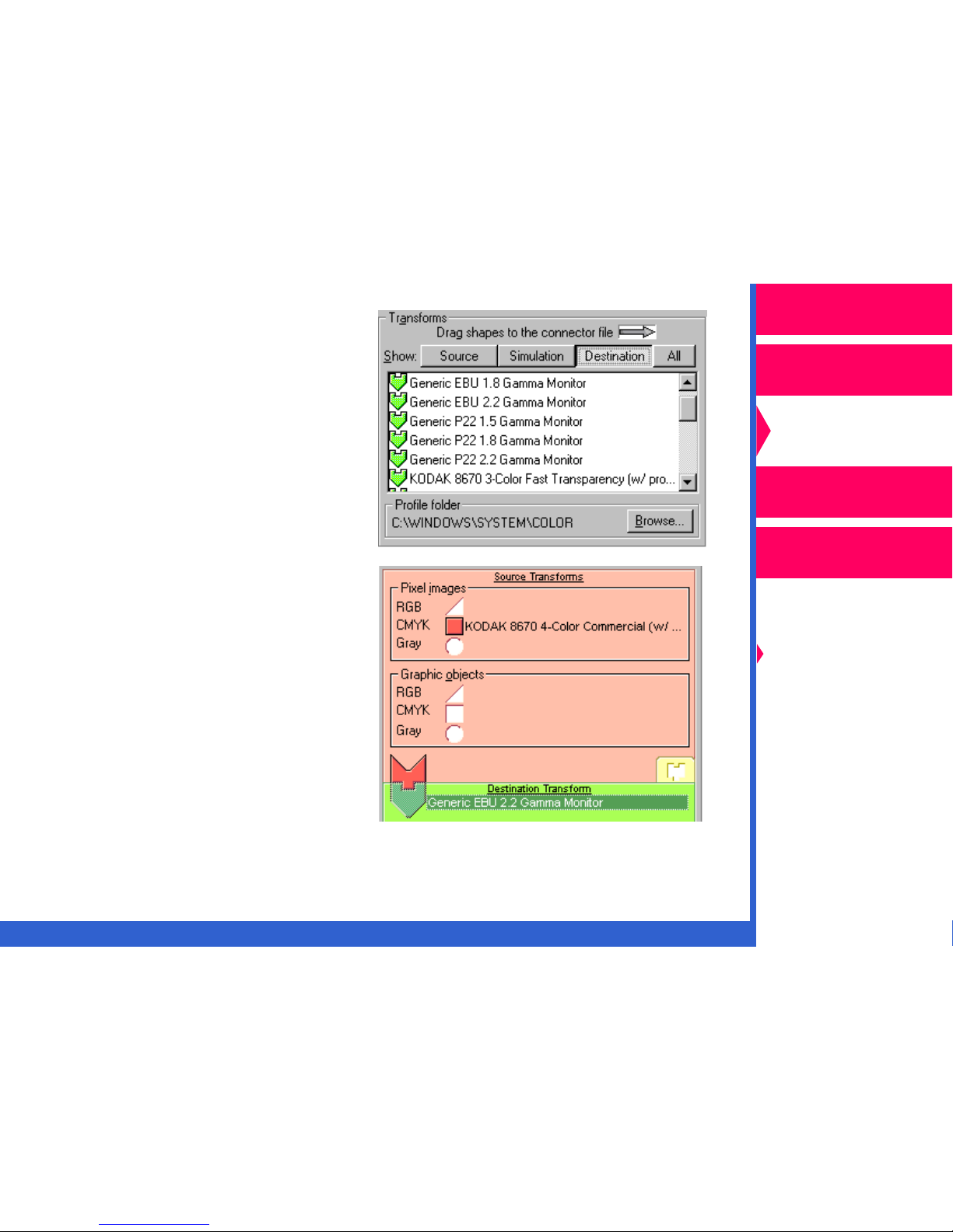
2.
Scroll through the list of
transforms, and select a
destination transform that
matches your output device.
Drag the green puzzle piece
for the destination transf orm to
the Destination Transform
socket in the color connector
template.
The destination puzzle piece
then appears over its place
holder indicating that the
requirement for a destination
transform is complete.
Operator’s Guide
Printing Guide
Color Management
Calibration
Network
Interface Guide
Color Management
Options
Using Color
Connector
Menus and Dialog
Boxes
CONTENTS
INDEX
SEARCH
HELP
Page 13
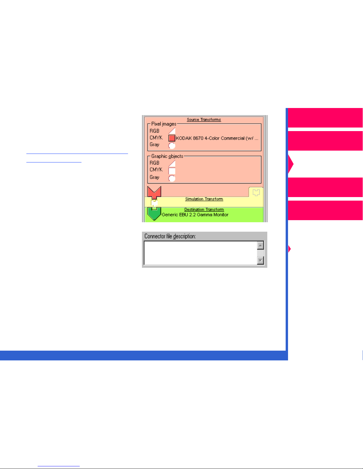
3.
Using a simulation transform
from the Transforms list is
optional. For instructions on
using the Simulation option,
er to “Simulating Another
ref
Output Device.”
Operator’s Guide
Printing Guide
Color Management
Calibration
Network
Interface Guide
4.
You may enter a description
of the color connector file you
created in the Connector file
description box. Entering a
description will help you to
identify the file when printing.
5.
Pull down the File menu, and select “Save”.
CONTENTS
INDEX
SEARCH
Color Management
Options
Using Color
Connector
Menus and Dialog
Boxes
HELP
Page 14
Matching Your Monitor to Your Printer’s Output
The following steps describe how to build a connector file so that the
colors in your computer monitor match the output from your printer.
NOTE: Monitors vary with model, age, and manufacturer. For optimum
results, make sure that the ICC Profile for your specific monitor
model is in the Transforms list.
Operator’s Guide
Printing Guide
Color Management
Your monitor should be calibrated. Refer to the documentation
that came with your monitor for instructions on how to calibrate it.
1.
In the Connector file options box:
•
make your selection for
Gamut alarm. Ref
er to
“Using Gamut Alar m.”
•
select the rendering intent
that is appropriate for your
job. Ref
er to “Setting
Rendering Intents.”
CONTENTS
INDEX
SEARCH
Calibration
Network
Interface Guide
Color Management
Options
Using Color
Connector
Menus and Dialog
Boxes
HELP
Page 15

2.
From the T ransf orms list, select
a pink triangle puzzle piece
that matches the name of your
monitor.
3.
Drag and drop the pink
triangle puzzle piece to
the appropriate Source
Transforms socket. The
piece appears in the RGB
or Gray socket. You will
hear a click.
Operator’s Guide
Printing Guide
Color Management
Calibration
Network
Interface Guide
Color Management
Options
Using Color
Connector
Menus and Dialog
Boxes
CONTENTS
INDEX
SEARCH
HELP
Page 16
NOTE: If you wish to add a simulation transform to the template so that
the job matches the output from another printing system, ref
er to
“Simulating Another Output Device.”
4.
From the Transforms list,
select a green puzzle piece
that matches your output
device and media
combination.
5.
Drag and drop the green
puzzle piece to the
Destination Transform
socket.
Operator’s Guide
Printing Guide
Color Management
Calibration
Network
Interface Guide
Color Management
Options
Using Color
Connector
Menus and Dialog
Boxes
CONTENTS
INDEX
SEARCH
HELP
Page 17

NOTE: If you selected a destination transform that was extracted from an
ICC Profile other than one that came with the 8660 printer, the
Select Printer dialog box appears.
Operator’s Guide
Printing Guide
Color Management
Calibration
Use the Printer model pull-down list to select the model of the
printer you are using. Click on
A dialog box similar to the one below appears that allows you to
select the media for the printer.
CONTENTS
INDEX
OK
.
SEARCH
Network
Interface Guide
Color Management
Options
Using Color
Connector
Menus and Dialog
Boxes
HELP
Page 18

The Printer Setup screen may appear differently depending on
the printer you are using.
Operator’s Guide
Make your media choices.
OK
Click on
.
6. You may enter a description
of the color connector file
you created in the Connector
file description box. Entering
a description will help you to
identify the file when
printing.
7. Pull down the File menu, and select “Save”.
8. To send the connector file to the printer to save as a default, ref
“Expor ting a Color Connector to the Printer as a Default.”
er to
Printing Guide
Color Management
Calibration
Network
Interface Guide
Color Management
Options
Using Color
Connector
Menus and Dialog
Boxes
CONTENTS
INDEX
SEARCH
HELP
Page 19

Color Managing Multiple Sources
The following steps describe how to build a connector file that applies
color management to multiple sources in one PostScript job.
NOTE: You can apply color management to up to six different types of
source transforms:
• RGB, CMY, and grayscale pixel images such as TIFF files or
scanned photographs.
• RGB, CMY, and grayscale graphic images such as EPS files or
text.
You cannot apply color management to multiple images from
different sources in the same color space. For example, you
cannot apply color management separately to two pixel RGB
images.
1. In the Connector file options
box:
• make your selection for
Gamut alarm. Ref
“Using Gamut Alar m.”
er to
Operator’s Guide
Printing Guide
Color Management
Calibration
Network
Interface Guide
Color Management
Options
Using Color
Connector
Menus and Dialog
Boxes
• select the rendering intent
that is appropriate for your
job. Ref
er to “Setting
Rendering Intents.”
CONTENTS INDEX SEARCH HELP
Page 20

2. From the Transforms list, select
the pink puzzle pieces that
match the images or objects to
which you wish to apply color
management.
Operator’s Guide
Printing Guide
Color Management
Calibration
Network
Interface Guide
NOTE: Make sure that the images or objects you select have not had any
previous color management applied to them.
If your file contains a source that uses PANTONE
® Color, leave
the socket empty for that color space.
CONTENTS INDEX SEARCH HELP
Color Management
Options
Using Color
Connector
Menus and Dialog
Boxes
Page 21

3. Drag and drop the pink puzzle
pieces to the appropriate
sockets in the Source
Transforms section of the
template.
Operator’s Guide
Printing Guide
Color Management
Calibration
Network
Interface Guide
NOTE: If you wish to add a simulation transform to the template so that
the job matches the output from another printing system, ref
er to
“Simulating Another Output Device.”
4. From the Transforms list, select
a green arrowhead-shaped
puzzle piece that matches your
output device and media
combination.
CONTENTS INDEX SEARCH HELP
Color Management
Options
Using Color
Connector
Menus and Dialog
Boxes
Page 22

5. Drag and drop the puzzle
piece to the Destination
Transform socket in the
template.
Operator’s Guide
Printing Guide
Color Management
Calibration
Network
Interface Guide
Color Management
Options
Using Color
Connector
Menus and Dialog
Boxes
CONTENTS INDEX SEARCH HELP
Page 23

NOTE: If you selected a destination transform that was extracted from an
ICC Profile other than one that came with the 8660 printer, click
on
Select
in the Printer setup por tion of the color connector
window.
The Select Printer Model dialog box appears.
Operator’s Guide
Printing Guide
Color Management
Calibration
Network
Interface Guide
Use the Printer model pull-down list to select the printer model.
A dialog box similar to the one below appears allowing you to
select the media for the printer.
CONTENTS INDEX SEARCH HELP
Color Management
Options
Using Color
Connector
Menus and Dialog
Boxes
Page 24

NOTE: The Printer Setup dialog box may appear differently depending
on the export module you are using.
OK
6. Select the correct media for the printer. Click on
.
7. You may enter a description
of the color connector file
you created in the
Connector file description
box. Entering a description
will help you to identify the
file when printing.
8. Pull down the File menu, and select “Save”.
Operator’s Guide
Printing Guide
Color Management
Calibration
Network
Interface Guide
9. To send your connector file to the printer to save as a default, ref
“Expor ting a Color Connector to the Printer as a Default.”.
CONTENTS INDEX SEARCH HELP
er to
Color Management
Options
Using Color
Connector
Menus and Dialog
Boxes
Page 25

Simulating Another Output Device
The following steps describe how to build a color connector file to produce
colors that simulate the look of other printing systems such as SWOP or
Euroscale.
Operator’s Guide
Printing Guide
1. In the Connector file options
box, select “Use simulation”.
2. Create a color connector file by selecting and dragging the
appropriate source and destination transform puzzle pieces to the
template. To create a color connector file that matches your monitor
to the printer’s output, ref
er to “Matching Your Monitor to Your
Printer’s Output.” To create a color connector file that manages
multiple sources, ref
er to “Color Managing Multiple Sources.”
Color Management
Calibration
Network
Interface Guide
Color Management
Options
Using Color
Connector
Menus and Dialog
Boxes
CONTENTS INDEX SEARCH HELP
Page 26

3. From the Transforms list, select
a yellow puzzle piece that
matches the name of the output
device you wish to simulate.
4. Drag and drop the puzzle piece
in the Simulation Transform
socket of the template.
NOTE: To send your color
connector file to the printer
as a default, ref
er to
“Expor ting a Color
Connector to the Printer as
a Default.”
Operator’s Guide
Printing Guide
Color Management
Calibration
Network
Interface Guide
Color Management
Options
Using Color
Connector
Menus and Dialog
Boxes
CONTENTS INDEX SEARCH HELP
Page 27

Using Gamut Alarm
Gamut alarm is a feature that allows you to determine if the simulation or
destination devices you selected for your connector file are capable of
accurately reproducing the colors of the previous device.
Operator’s Guide
Printing Guide
When you select one of the gamut alarm modes, any areas of your image
that are out of gamut are printed in black. All other areas are pr inted in
white.
Color Management
Calibration
Network
Interface Guide
Color Management
Options
Using Color
Connector
Menus and Dialog
Boxes
CONTENTS INDEX SEARCH HELP
Page 28

NOTE: When you set gamut alarm to
either “Destination” or
“Simulation”, the puzzle
pieces in the sockets are
black.
Operator’s Guide
Printing Guide
To set gamut alarm:
NOTE: To use gamut alarm in the
Simulation mode, be sure
that you select the “Use
simulation” check box.
1. Pull down the Gamut alarm list,
and select either:
• “Simulation” to determine if the colors of the source transform are
out of the gamut of the simulation device
or
• “Destination” to determine if the colors of the simulation or source
device are out of the gamut of the destination device.
2. Create your color connector file. Ref
Sources.” When you print the file, any out-of-gamut areas are printed
in black.
3. To adjust the color representation in any out-of-gamut areas, ref
“Setting Render ing Intents.”
er to “Color Managing Multiple
Color Management
Calibration
Network
Interface Guide
Color Management
Options
Using Color
Connector
Menus and Dialog
Boxes
er to
CONTENTS INDEX SEARCH HELP
Page 29

Setting Rendering Intents
Rendering intents control the ways in which color connector translates the
colors from the source transform to the simulation transform and the
source or simulation transform to the destination transform when they are
out of gamut. The rendering intent deals with the color differences
between the transforms. For example, if the color of a scanned image is
out of the gamut of the destination device, the destination device cannot
reproduce that color. The color must be represented by another color that
is close to the desired color. Rendering intents deter mine how out-ofgamut colors are substituted.
Automatic Rendering
Operator’s Guide
Printing Guide
Color Management
Calibration
Network
Interface Guide
You can let color connector set Rendering for you by selecting one of the
automatic settings from the Rendering drop-down list box. The automatic
settings set rendering intents for the individual transforms by comparing
their color gamuts. Both of these settings give a pleasing look but not
necessarily the most accurate reproduction.
Custom Rendering
To more closely control the way in which color connector adjusts the
differences in color representation, use the Custom Rendering
option.This option allows you to set the rendering intents individually for
all the source and simulation transforms.
CONTENTS INDEX SEARCH HELP
Color Management
Options
Using Color
Connector
Menus and Dialog
Boxes
Page 30

Setting Automatic Rendering
To set automatic rendering intents:
Operator’s Guide
Pull down the Rendering drop-down list, and select either:
• “Auto—Photographic” for
scanned photographs. Color
connector attempts to
maintain the correct hue by
adjusting the color saturation
for the out-of-gamut colors
or
• “Auto—Presentation” for
computer-generated graphics,
charts, graphics. Color
connector tries to maintain
saturation at the expense of
the correct hue for the out-ofgamut colors.
Printing Guide
Color Management
Calibration
Network
Interface Guide
Color Management
Options
Using Color
Connector
Menus and Dialog
Boxes
CONTENTS INDEX SEARCH HELP
Page 31

Setting Custom Rendering
Do the following steps to set custom rendering.
Operator’s Guide
NOTE: If you wish to set custom rendering for more than one puzzle
piece in the template, you need to repeat this procedure for each
piece.
1. Pull down the Rendering
drop-down list box, and
select “Custom”.
2. Build the connector file you need for your job. Ref
er to “Color
Managing Multiple Sources.”
3. Double-click on the source or simulation puzzle piece in the color
connector socket in the template for which you wish to set custom
rendering.
Printing Guide
Color Management
Calibration
Network
Interface Guide
Color Management
Options
Using Color
Connector
Menus and Dialog
Boxes
CONTENTS INDEX SEARCH HELP
Page 32

The Transform Information dialog box appears.
Operator’s Guide
Printing Guide
Color Management
Calibration
Network
Interface Guide
Color Management
Options
Using Color
Connector
Menus and Dialog
Boxes
A Recommendation box gives you two recommended settings based
on a comparison of gamuts. If you select a different rendering intent,
the Effect box changes to describe the expected results.
CONTENTS INDEX SEARCH HELP
Page 33

4. Pull down the Rendering intent list box, and select a rendering intent
from the following options:
Operator’s Guide
• Perceptual—compresses the gamut of the image while maximizing
the color. Use this rendering intent for photographic images.
• Saturation—compresses the gamut of the image while maximizing
the color saturation. Use this rendering intent for presentation
graphics.
• Relative Colorimetric—compresses the gamut of the image for
brightness, and clips the gamut for color. Use this rendering intent
when you wish to match a particular color.
• Absolute Colorimetric—Clips the gamut of the image. Use this
rendering intent when you wish to match a particular color and
simulate the background of the paper.
OK
5. Click on
.
Printing Guide
Color Management
Calibration
Network
Interface Guide
Color Management
Options
Using Color
Connector
Menus and Dialog
Boxes
CONTENTS INDEX SEARCH HELP
Page 34

Exporting a Color Connector to the Printer as a
Default
Color Connector Memory Locations in Printers
Operator’s Guide
Printing Guide
Printers that suppor t color connector contain color management memory
locations. These memory locations store color management information,
and are defined by a media combination for ribbon and paper.
For example, if a printer has two ribbon types and one paper type, the
printer might have two memory locations:
• Photographic paper with a CMY ribbon
• Photographic paper with a black ribbon
When you send a job to the printer that uses the media combination for
that memory location, the default connector file is applied if you do not
select another connector file.
Exporting a connector file as a default stores frequently-used color
management information permanently in the printer. This eliminates the
need for individual users to apply color management to their jobs as long
as they use the default media combinations.
Color Management
Calibration
Network
Interface Guide
Color Management
Options
Using Color
Connector
Menus and Dialog
Boxes
CONTENTS INDEX SEARCH HELP
Page 35

Exporting a Color Connector File to be a Printer Default
After you create your connector file, do the following steps to send it to
the printer as a default:
1. Make sure that you save the file.
Operator’s Guide
Printing Guide
2. From the File menu, select “Export As Printer’s Default”.
The “Select Printer Model” dialog box appears.
3. Select the printer model from the drop-down list.
OK
4. Click on
.
NOTE: If this is the first time you have created a connector file, a dialog
OK
box appears asking you to locate the media file. Click on
.
Select the correct media file in the dialog box that appears. Click
on
Open
.
Color Management
Calibration
Network
Interface Guide
Color Management
Options
Using Color
Connector
Menus and Dialog
Boxes
CONTENTS INDEX SEARCH HELP
Page 36

Selecting a Printer
Macintosh systems
If the 8660 printer:
• has a network
connection, click on
Network
Select a Kodak
Professional 8660
thermal printer
dialog box.
In the selection box
that opens, choose
the correct 8660
printer. Click on
to return to the
Select a Kodak
Professional 8660
thermal printer dialog box.
in the
OK
Operator’s Guide
Printing Guide
Color Management
Calibration
Network
Interface Guide
Color Management
Options
Using Color
Connector
Menus and Dialog
Boxes
• has a SCSI connection to your computer, click on the radio button for
the correct 8660 printer.
CONTENTS INDEX SEARCH HELP
Page 37

Windows systems
If the 8660 printer:
Operator’s Guide
• has a SCSI
connection, click on
the radio button f or the
correct 8660 printer.
• has a network
connection, click on
Network
Browse
. Click on
, and locate
the correct printer in
the Browse for Printer
dialog box that opens.
OK
Click on
in the
Network Printer dialog
box to return to the
Select a Printer dialog box.
• has a parallel connection, click on the radio button for either LPT1 or
LPT2 to select the printer.
NOTE: If your host computer has more than one SCSI host adapter
installed, pull down the SCSI Host Adapter list. Select the port
address for the SCSI host adapter connected to the 8660 printer.
Printing Guide
Color Management
Calibration
Network
Interface Guide
Color Management
Options
Using Color
Connector
Menus and Dialog
Boxes
CONTENTS INDEX SEARCH HELP
Page 38

The Printer Default
Connector Files dialog
box appears.
NOTE: If you hav e more than
one 8660 printer,
click on
Printer
Select
to locate the
correct printer for
exporting.
Operator’s Guide
Printing Guide
Color Management
Calibration
5. Click on
Set as Printer
Default.
If your printer has a bidirectional connection
such as SCSI or
AppleTalk, the memor y
location for the connector
file you exported will be
added to the list in the
Printer default connector
files window. If the
connector file does not
appear, click on
Update
.
If your printer has a parallel connection, this information does not
appear in the Printer default connector files window.
CONTENTS INDEX SEARCH HELP
Network
Interface Guide
Color Management
Options
Using Color
Connector
Menus and Dialog
Boxes
Page 39

NOTE: You are prompted if the connector file you are sending to the
printer as a default has the same media combination as another
default connector file. If you wish to send a connector file to the
printer as a default for a media combination that already exists,
delete all the default connector files before you send the new
default to the printer. You can then resend the other default
connector files to the printer. Ref
er to “Deleting Color Connector
Files.”
Operator’s Guide
Printing Guide
Color Management
Calibration
Network
Interface Guide
Color Management
Options
Using Color
Connector
Menus and Dialog
Boxes
CONTENTS INDEX SEARCH HELP
Page 40

Deleting Color Connector Files
Operator’s Guide
Clicking on
Delete All
in the
Printer Default Connector
Files dialog box deletes all
the default color connector
files stored in the 8660
printer.
Printing Guide
Color Management
Calibration
Network
Interface Guide
Color Management
Options
Using Color
Connector
Menus and Dialog
Boxes
CONTENTS INDEX SEARCH HELP
Page 41

Exporting a Color Connector File as an ICC DeviceLink
Profile
Operator’s Guide
You can export a color connector file as a DeviceLink profile so that it can
be used with other color management applications.
NOTE: The color connector file that you export as a DeviceLink profile
can contain only one source transform.
1. From the File menu, select “Export As ICC DeviceLink Profile”.
2. In the dialog box that appears, enter a name for the color connector
file. Select the folder where you want the file to reside.
OK
3. Click on
.
Printing Guide
Color Management
Calibration
Network
Interface Guide
Color Management
Options
Using Color
Connector
Menus and Dialog
Boxes
CONTENTS INDEX SEARCH HELP
Page 42

Menus and Dialog Boxes
This section describes the menus and dialog box options used in the
Kodak Professional Colorflow ICC color connector (color connector). The
Windows menus and dialog boxes that are shown are similar to the
Macintosh screens and have identical functionality.
File Menu
This section describes the options on the File menu.
Operator’s Guide
Printing Guide
Color Management
Calibration
Network
Interface Guide
Color Management
Options
Using Color
Connector
Menus and Dialog
Boxes
New—opens a new connector file.
Open—accesses a file open dialog box so you can select an existing
connector file.
Close—closes the current connector file.
CONTENTS INDEX SEARCH HELP
Page 43

Save—saves changes to the current connector file.
Save As—accesses a dialog box in which you can specify a new name
and location for the current connector file.
Export As Printer’s Default—accesses a dialog box that allows you to
select a default printer for the connector file.
Export As ICC DeviceLink Profile—saves the transforms in a connector
file as a DeviceLink profile so that they can be used with other color
management applications.
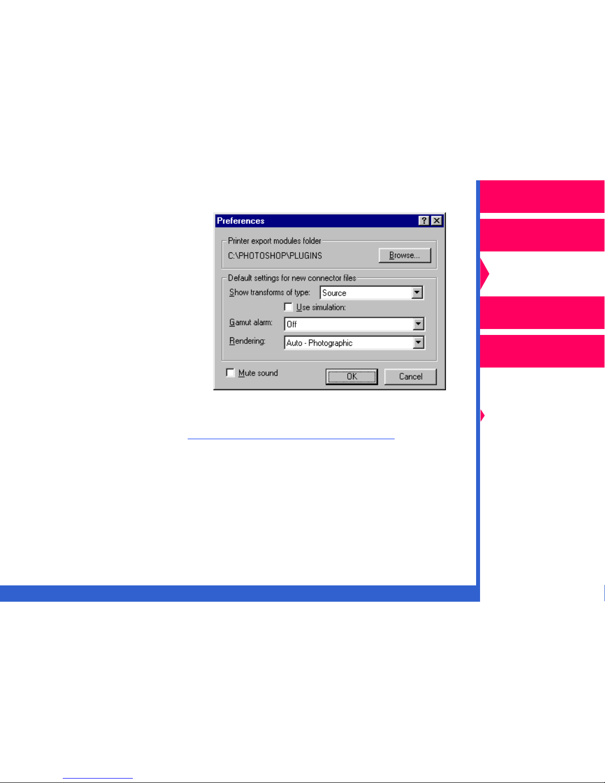
Preferences—accesses a dialog box that allows you to mute the sound,
and select the folder for the export module, the default settings for Gamut
alarm and Rendering, and the type of transforms that display in the
Transforms list.
Operator’s Guide
Printing Guide
Color Management
Calibration
Network
Interface Guide
Color Management
Options
Using Color
Connector
Menus and Dialog
Boxes
Quit—exits the color connector application.
CONTENTS INDEX SEARCH HELP
Page 44

Edit Menu
The Edit menu is enabled when the Connector file description dialog box
contains editable text.
Transform Menu
The Transform menu is enabled when a color connector window is open.
Operator’s Guide
Printing Guide
Color Management
Calibration
Network
Interface Guide
Color Management
Options
Using Color
Connector
Menus and Dialog
Boxes
CONTENTS INDEX SEARCH HELP
Page 45

View Info and Options—accesses the Transform Information window for
the selected transform in the Transforms list.
Clear T ransform—Removes the selected transform from a socket in the
color connector template.
Operator’s Guide
Printing Guide
Color Management
Calibration
Network
Interface Guide
Color Management
Options
Using Color
Connector
Show by Profile File Name—Displays the transforms in the Transform list
and the color connector template by the ICC Profile that the transform
was extracted from.
Show by Profile Description—Displays the transforms in the Transform
list and the color connector template by their description.
CONTENTS INDEX SEARCH HELP
Menus and Dialog
Boxes
Page 46

Colorflow Color Connector Window
Use the Colorflow color connector window to create new and edit existing
connector files.
Operator’s Guide
Printing Guide
Color Management
Calibration
Network
Interface Guide
Color Management
Options
Using Color
Connector
Menus and Dialog
Boxes
CONTENTS INDEX SEARCH HELP
Page 47

Access a new connector file by pulling down the File menu and selecting
“New”. Open an existing color connector file by selecting “Open” from the
File menu and then locating the file from the file selection box that opens.
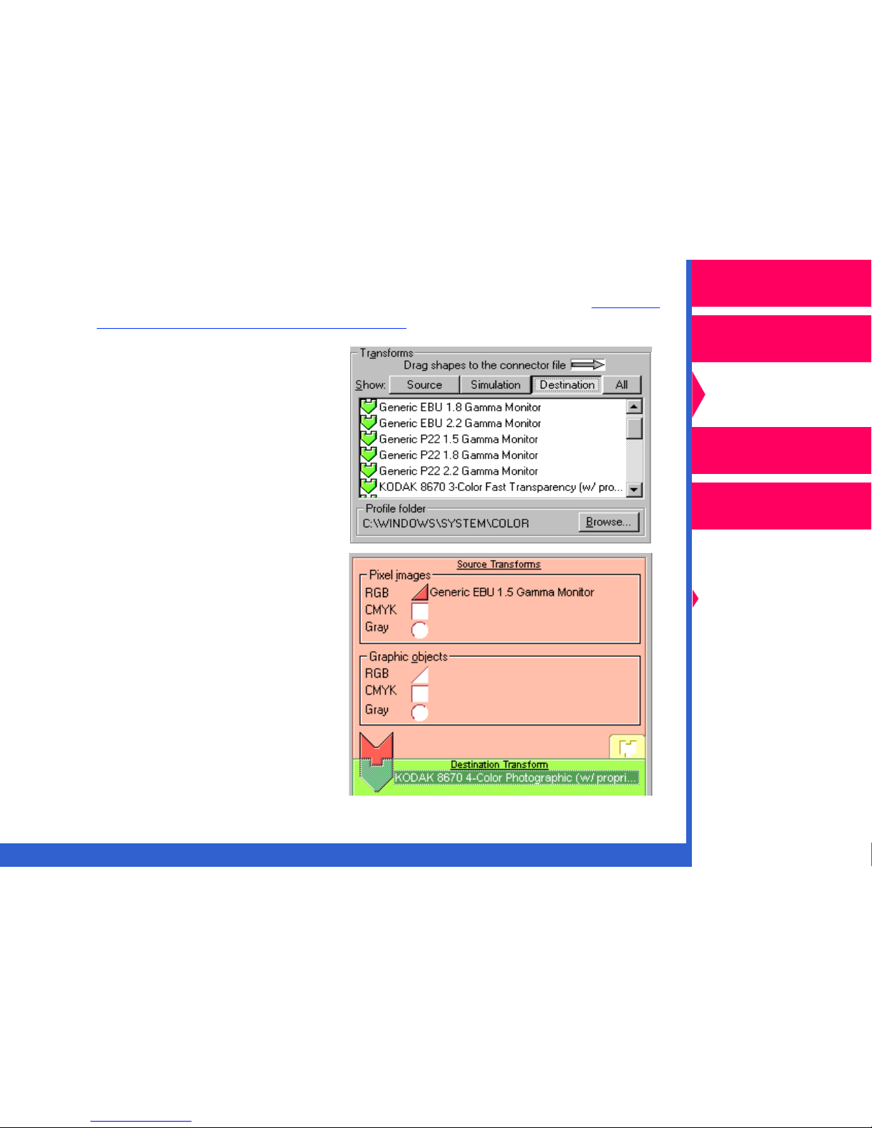
Transforms
The Transforms list displays the
transforms contained in the ICC
profiles in the currently-selected
profiles folder. The transforms
are listed by type and
represented by icons:
• RGB source—Triangle
• CMYK source—Square
• Grayscale source—Circle
Operator’s Guide
Printing Guide
Color Management
Calibration
Network
Interface Guide
Color Management
Options
• Simulation Puzzle Piece
• Destination Puzzle Piece
Show T ransf orms of Type
This list allows you to select the transforms to display in the list of
Transforms. The choices are “All”, “Source Only”, “Simulation Only”, and
“Destination”.
CONTENTS INDEX SEARCH HELP
Using Color
Connector
Menus and Dialog
Boxes
Page 48

Profiles Folder
Clicking on
Browse (Select
in Macintosh) accesses a file selection box
which allows you to select the folder containing the ICC Profiles you wish
to display in the Transforms list.
Operator’s Guide
Printing Guide
Color Management
Calibration
Network
Interface Guide
Color Management
Options
Using Color
Connector
Menus and Dialog
Boxes
CONTENTS INDEX SEARCH HELP
Page 49

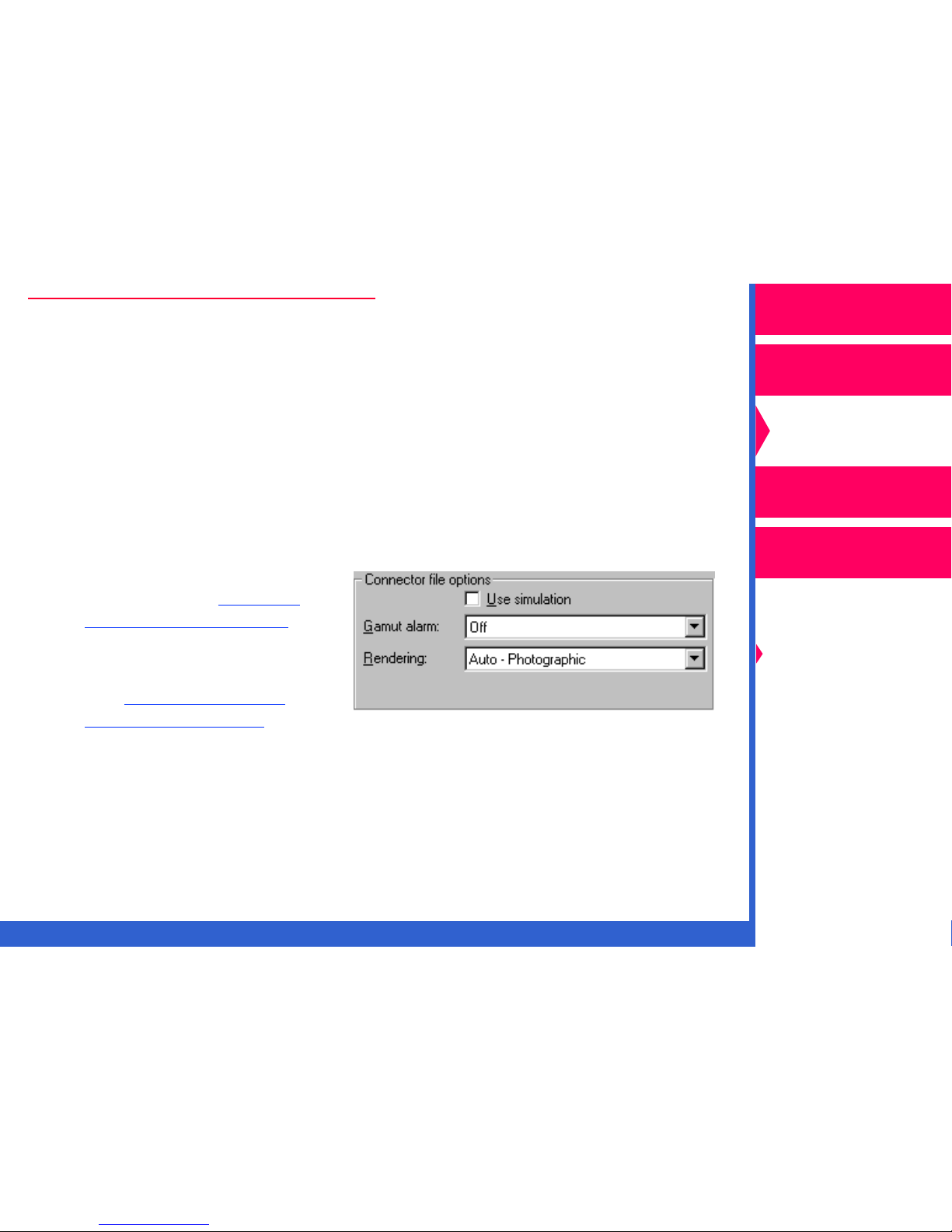
Connector File Options
This portion of the color connector window displays the options you can
select for your color connector file.
Operator’s Guide
Printing Guide
Color Management
Calibration
Use Simulation
Checking the Use simulation check box opens the Simulation Transform
socket in the template and allows you to drag a simulation transform
puzzle piece to that socket. If the Use simulation check box is not
checked, the simulation portion of the template is hidden.
Gamut Alarm
Gamut alarm causes any prints made with a color connector file to print
only the portions of the image that are out of the gamut of the selected
source or destination transform. The choices are “Off”, “Simulation”, and
“Destination”.
When you select “Simulation” or “Destination”, the puzzle piece for a
simulation or destination transform is black indicating that you are using
Gamut alarm. If the Use simulation checkbox is not checked, Use
simulation is not available.
CONTENTS INDEX SEARCH HELP
Network
Interface Guide
Color Management
Options
Using Color
Connector
Menus and Dialog
Boxes
Page 50

Connector File Description
Allows you to enter a description of your connector file to help you identify
the file when printing.
Operator’s Guide
Printing Guide
Color Management
Rendering
Rendering is the approach color connector uses to translate the colors of
the image to the color gamut of a destination or simulation transform. The
choices for this option are “Auto-Photographic”, “Auto-Presentation”, or
“Custom”. You can let color connector set Rendering for you by selecting
either “Auto-Photographic” or “Auto-Presentation”.
CONTENTS INDEX SEARCH HELP
Calibration
Network
Interface Guide
Color Management
Options
Using Color
Connector
Menus and Dialog
Boxes
Page 51

Select “Custom” to choose
your own rendering intent. If
a transform in the source or
simulation socket of a color
connector is editable,
double-clicking on it
accesses the Transform
Information dialog box.
Operator’s Guide
Printing Guide
Color Management
The dialog box gives you a
recommended intent and the
effect it will produce on your
output.
The options in the
Simulation-to-destination
pull-down list are:
• Perceptual
• Saturation
• Relative Colorimetric
• Absolute Colorimetric
Clicking on
sets the rendering intent you selected. Clicking on
Cancel
OK
cancels your selections and closes the Transform Information dialog box.
CONTENTS INDEX SEARCH HELP
Calibration
Network
Interface Guide
Color Management
Options
Using Color
Connector
Menus and Dialog
Boxes
Page 52

Connector File
The Connector file window contains
the template. Drag the puzzle pieces
selected in the Transforms list to the
sockets in the template.
Operator’s Guide
Printing Guide
Source T ransf orms
The Source Transforms sockets of
the template only accepts
transforms from the Transforms list
with the corresponding shape. A
connector file must contain at least
one source transform.
Simulation T ransf orm
Using simulation is optional. Check
the Use Simulation check box in the
Connector file options box for the
Simulation Transform socket to be
visible.
Destination T ransform
A connector file requires a
destination transform.
Color Management
Calibration
Network
Interface Guide
Color Management
Options
Using Color
Connector
Menus and Dialog
Boxes
CONTENTS INDEX SEARCH HELP
Page 53

If the destination transform is extracted from an ICC Profile provided on
the CD for the printer, the “Printer model” and “Media” fields contain a
description of the printer and media for the printer.
If the destination transform is from a profile that was not included on the
CD, the Printer model and Media fields are empty, and the Select button is
enabled. Clicking on
Select
opens the Select Printer Model dialog box.
Use the pull-down list to select the model of your printer.
Operator’s Guide
Printing Guide
Color Management
Calibration
Network
Interface Guide
Color Management
Options
Using Color
Connector
Menus and Dialog
Boxes
CONTENTS INDEX SEARCH HELP
 Loading...