

Page 1

User’s Guide Part No. 3H0594
KODAK PROFESSIONAL
8657 Printer
Page 2

Contents
Introduction v. . . . . . . . . . . . . . . . . . . . . . . . . . . . . . . . . . . . . . . . . . . . . . . . . . . . .
About Your Printer v. . . . . . . . . . . . . . . . . . . . . . . . . . . . . . . . . . . . . . . . . .
Host Interfaces vi. . . . . . . . . . . . . . . . . . . . . . . . . . . . . . . . . . . . . . . . . . .
Radio Frequency Interference vii. . . . . . . . . . . . . . . . . . . . . . . . . . . . . . . .
Regulatory Information viii. . . . . . . . . . . . . . . . . . . . . . . . . . . . . . . . . . . . . .
Safety Regulations ix. . . . . . . . . . . . . . . . . . . . . . . . . . . . . . . . . . . . . . . . .
1 Getting Started 1–1. . . . . . . . . . . . . . . . . . . . . . . . . . . . . . . . . . . . . . . . . . . . . . .
Checking Contents 1–1. . . . . . . . . . . . . . . . . . . . . . . . . . . . . . . . . . . . . . . . .
Removing the Shipping Pins 1–2. . . . . . . . . . . . . . . . . . . . . . . . . . . . . . . . .
Finding a Location 1–3. . . . . . . . . . . . . . . . . . . . . . . . . . . . . . . . . . . . . . . . . .
Components of the Printer 1–4. . . . . . . . . . . . . . . . . . . . . . . . . . . . . . . . . . .
Reviewing the Components 1–4. . . . . . . . . . . . . . . . . . . . . . . . . . . . . . . .
Attaching the Power Cord 1–9. . . . . . . . . . . . . . . . . . . . . . . . . . . . . . . . . .
Attaching the Interface Cable 1–10. . . . . . . . . . . . . . . . . . . . . . . . . . . . . . .
Cleaning the Thermal Head 1–13. . . . . . . . . . . . . . . . . . . . . . . . . . . . . . . .
Printer Ribbon and Paper 1–16. . . . . . . . . . . . . . . . . . . . . . . . . . . . . . . . . . . .
About Ribbon 1–16. . . . . . . . . . . . . . . . . . . . . . . . . . . . . . . . . . . . . . . . . . . .
About Paper 1–21. . . . . . . . . . . . . . . . . . . . . . . . . . . . . . . . . . . . . . . . . . . . .
Turning on the Power 1–24. . . . . . . . . . . . . . . . . . . . . . . . . . . . . . . . . . . . . . .
Understanding the Display Panel 1–25. . . . . . . . . . . . . . . . . . . . . . . . . . . . .
Indicator Lights 1–26. . . . . . . . . . . . . . . . . . . . . . . . . . . . . . . . . . . . . . . . . . .
LCD Panel 1–27. . . . . . . . . . . . . . . . . . . . . . . . . . . . . . . . . . . . . . . . . . . . . . .
Buttons 1–28. . . . . . . . . . . . . . . . . . . . . . . . . . . . . . . . . . . . . . . . . . . . . . . . . .
January 1998
i
Page 3

Contents
Configuring the Printer 1–29. . . . . . . . . . . . . . . . . . . . . . . . . . . . . . . . . . . . . .
Using Setup Menus 1–29. . . . . . . . . . . . . . . . . . . . . . . . . . . . . . . . . . . . . . .
Selecting a Language for the Display Panel 1–30. . . . . . . . . . . . . . . . . .
Selecting Defaults 1–30. . . . . . . . . . . . . . . . . . . . . . . . . . . . . . . . . . . . . . . .
Specifying Port Information 1–31. . . . . . . . . . . . . . . . . . . . . . . . . . . . . . . .
Making a Test Print 1–35. . . . . . . . . . . . . . . . . . . . . . . . . . . . . . . . . . . . . . . . .
Printing 1–36. . . . . . . . . . . . . . . . . . . . . . . . . . . . . . . . . . . . . . . . . . . . . . . . . . .
Job Scheduling 1–37. . . . . . . . . . . . . . . . . . . . . . . . . . . . . . . . . . . . . . . . . . .
Storing Prints 1–38. . . . . . . . . . . . . . . . . . . . . . . . . . . . . . . . . . . . . . . . . . . . . .
2 Maintaining the Printer 2–1. . . . . . . . . . . . . . . . . . . . . . . . . . . . . . . . . . . . . . . .
3 Supplies 3–1. . . . . . . . . . . . . . . . . . . . . . . . . . . . . . . . . . . . . . . . . . . . . . . . . . . . .
Ordering Supplies 3–1. . . . . . . . . . . . . . . . . . . . . . . . . . . . . . . . . . . . . . . . . .
Alcohol Cleaning Pads 3–1. . . . . . . . . . . . . . . . . . . . . . . . . . . . . . . . . . . .
Ribbon 3–1. . . . . . . . . . . . . . . . . . . . . . . . . . . . . . . . . . . . . . . . . . . . . . . . . .
Paper 3–2. . . . . . . . . . . . . . . . . . . . . . . . . . . . . . . . . . . . . . . . . . . . . . . . . . .
Storing Supplies 3–3. . . . . . . . . . . . . . . . . . . . . . . . . . . . . . . . . . . . . . . . . . . .
Ribbon 3–3. . . . . . . . . . . . . . . . . . . . . . . . . . . . . . . . . . . . . . . . . . . . . . . . . .
Paper 3–4. . . . . . . . . . . . . . . . . . . . . . . . . . . . . . . . . . . . . . . . . . . . . . . . . . .
ii
January 1998
Page 4

Contents
4 Correcting Problems 4–1. . . . . . . . . . . . . . . . . . . . . . . . . . . . . . . . . . . . . . . . . .
Understanding Error Messages 4–1. . . . . . . . . . . . . . . . . . . . . . . . . . . . . .
Ribbon Type Mismatch 4–3. . . . . . . . . . . . . . . . . . . . . . . . . . . . . . . . . . . .
Troubleshooting 4–4. . . . . . . . . . . . . . . . . . . . . . . . . . . . . . . . . . . . . . . . . . . .
Handling for Humidity-related Paper Problems 4–8. . . . . . . . . . . . . . . . .
Alternate Head Cleaning Instructions 4–9. . . . . . . . . . . . . . . . . . . . . . . . . .
Clearing the Paper Path 4–12. . . . . . . . . . . . . . . . . . . . . . . . . . . . . . . . . . . . .
Repacking the Printer 4–15. . . . . . . . . . . . . . . . . . . . . . . . . . . . . . . . . . . . . . .
Getting Help 4–17. . . . . . . . . . . . . . . . . . . . . . . . . . . . . . . . . . . . . . . . . . . . . . .
Asia/Pacific Helpline Numbers 4–18. . . . . . . . . . . . . . . . . . . . . . . . . . . . . .
European Helpline Numbers 4–18. . . . . . . . . . . . . . . . . . . . . . . . . . . . . . .
Appendix A Printer Specifications A–1. . . . . . . . . . . . . . . . . . . . . . . . . . . . . . .
Size A–1. . . . . . . . . . . . . . . . . . . . . . . . . . . . . . . . . . . . . . . . . . . . . . . . . . . . . .
Weight A–1. . . . . . . . . . . . . . . . . . . . . . . . . . . . . . . . . . . . . . . . . . . . . . . . . . . .
Operating Environment A–1. . . . . . . . . . . . . . . . . . . . . . . . . . . . . . . . . . . . . .
Space Requirements A–1. . . . . . . . . . . . . . . . . . . . . . . . . . . . . . . . . . . . . . .
Power Requirements A–2. . . . . . . . . . . . . . . . . . . . . . . . . . . . . . . . . . . . . . .
Appendix B Adding More Memory B–1. . . . . . . . . . . . . . . . . . . . . . . . . . . . . . . .
Setting up for the Installation B–1. . . . . . . . . . . . . . . . . . . . . . . . . . . . . . .
Opening the Printer B–3. . . . . . . . . . . . . . . . . . . . . . . . . . . . . . . . . . . . . . .
Installing the Card B–6. . . . . . . . . . . . . . . . . . . . . . . . . . . . . . . . . . . . . . . .
Closing the Printer B–7. . . . . . . . . . . . . . . . . . . . . . . . . . . . . . . . . . . . . . . .
Appendix C About SCSI-connected Installations C–1. . . . . . . . . . . . . . . . . .
Index
January 1998
Windows systems C–1. . . . . . . . . . . . . . . . . . . . . . . . . . . . . . . . . . . . . . . . . .
Macintosh Systems C–3. . . . . . . . . . . . . . . . . . . . . . . . . . . . . . . . . . . . . . . . .
iii
Page 5

Introduction
About Your Printer
Thank you for purchasing the KODAK PROFESSIONAL 8657 Printer.
The 8657 Printer is a thermal dye diffusion device with superior
printing speed. It contains a 33 MHz MIPS RISC processor and has a
resolution of 300 pixels per inch (PPI). Printed images are high-contrast
and long lasting, and XtraLife ribbon can be used to protect images from
fingerprints.
A number of communication ports are provided on the printer. In addition
to these standard ports, the optional KODAK Network Interface Card
allows your printer to tie in to networks using Ethernet cabling.
January 1998
v
Page 6

Introduction
Host Interfaces
The Centronics (Parallel) and SCSI interfaces are standard with the
printer.
The EtherTalk, Novell NetWare and TCP/IP Ethernet interfaces are
provided through the optional Network Interface Card.
This manual contains the information necessary for setting up and using
your 8657 Printer. It consists of four chapters:
Getting Started, Maintaining the Printer, Supplies,
Problems.
Specifications,
Additional information is provided in the appendices
and
Customizing Your Printer.
and
Correcting
Printer
vi
January 1998
Page 7

Introduction
Radio Frequency Interference
This equipment generates, uses, and can radiate radio frequency energy.
If it is not installed and used in accordance with the User’s Guide, this
energy may cause interference to radio and television reception.
This equipment has been type tested and found to comply with the following:
This device meets FCC Class B emission limits for verification pursuant
to Part 15 of the Federal Communications Commission Rule of the
United States.
“The class B limits for radio noise emissions from digital apparatus as set
out in the interference-causing equipment standard entitled “Digital
Apparatus”, ICES–003 of the Department of Communications.”
“Cet appareil numérique respecte les limites de bruits radioléctriques
applicables aux appareils numériques de Classe B prescrites dans la
norme sur le matriél brouilleur : “Appareils Numériques”, NMB–003
édicté par le minstre des Communications.”
47CFR Part 15 SubPart B (North American – USA) – Class B
ICES–003 (North American – Canada) – Class B
January 1998
VCCI–2 (Japan) – Class B
Requirements of the EMC directive 89/336/EEC were met through
compliance with the following:
EN50081–1 (European – EU) consists of: EN55022 (class B)
EN60555 – 2
(powerline harmonics)
EN50082–1 (European – EU) consists of: IEC 801 – 2/91 (ESD)
IEC 801 – 3/84
(rf immunity)
IEC 801 – 4/88 (EFT)
“Changes or modifications not expressly approved by the party responsible
for compliance could void the user’s authority to operate the equipment.”
vii
Page 8

Introduction
Regulatory Information
The foregoing limits are designed to provide reasonable protection
against harmful interference when operated in a residential installation.
However, there is no guarantee that interference will not occur in a
particular location. If this equipment does cause interference to radio or
television reception (determined by turning the equipment off and on),
you are encouraged to try to correct the interference by one or more of
the following measures:
Reorient or relocate the receiving antenna
Relocate the printer with respect to the receiver
Move the printer away from the receiver
Plug the printer into a different outlet so that the receiver and printer
are on different branch circuits
If problems persist consult an experienced radio/television technician for
additional suggestions. You may also find the following booklet, prepared
by the Federal Communications Commission, helpful: “How to Identify
and Resolve Radio–TV Interference Problems.” This booklet can be
purchased by contacting the Superintendent of Documents, U.S.
Government Printing Office, Washington, DC 20402.
viii
January 1998
Page 9

Introduction
Important
This equipment was tested using shielded interface cables. The use of
these cables is required to reduce the possibility of causing interference
to radio and television reception.
Das Gerät ist gemäß Amtsblattberfügung 243/91 funkenstört und wurde
der Deutschen Bundespost gemeldet. Kodak AG, Stuttgart.
DIESES GERÄT WURDE SOWOHL EINZELN ALS IN EINER ANLAGE,
DIE EINEN NORMALEN ANWENDUNGSFALL NACHBILDET, AUF DIE
EINHALTUNG DER FUNKENTSTÖRBESTIMMUNGEN GEPRÜFT. ES
IST JEDOCH MÖGLICH, DASS DIE FUNKENSTÖRBESTIMMUNGEN
UNTER UNGÜNSTIGEN UMST ÄNEN BEI ANDEREN
GERÄTEKOMBINATIONEN NICHT EINGEHALTEN WERDEN. DER
BETREIBER IST FÜR DIE EINHAL TUNG DER FUNKENTSTÖRUNGS
BESTIMMUNGEN SEINER GESAMTEN ANLAGE VERANTWORTLICH,
IN DER DIESES GERÄ T BETRIEBEN WIRD.
This equipment has been tested and found to comply with the following:
UL 1950
CSA 950
TUV EN60950
Safety Regulations
January 1998
The following symbol has been placed on areas of the printer where
electrical shock is possible. Take extra precautions in these areas.
ix
Page 10
1 Getting Started
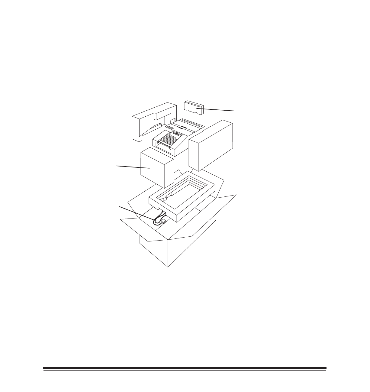
Checking Contents
As you unpack your new printer, make sure the following items
are included:
Paper tray
Power cord
Language Kit
Included in this box: - Cleaner Kit
- SCSI terminator - Head cleaning pads (4)
- CD-ROM containing software and
documentation for the printer
January 1998
Contact your place of purchase if any items are missing from the box.
1–1
Page 11
Getting Started
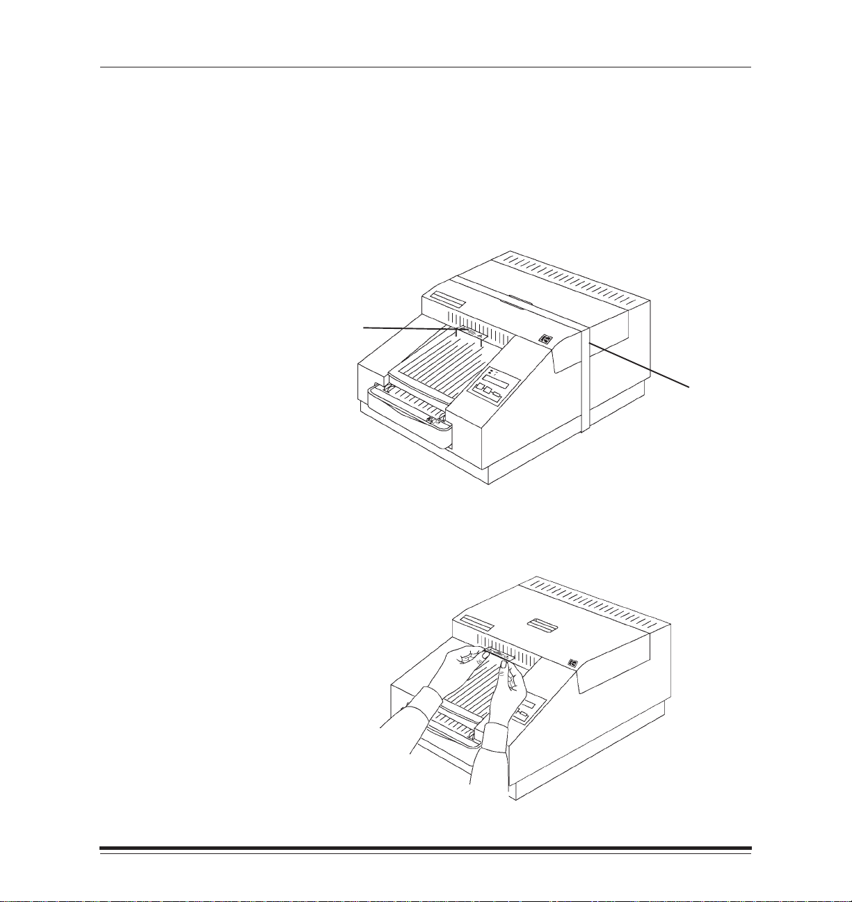
Removing the Shipping Pins
Shipping pins are used to ensure safe shipment of your 8657 Printer.
Save the printer’s packaging and these pins in case you need to ship
your printer in the future.
CAUTION:Do not use the printer until you remove the shipping pins.
1. Remove the printer from the plastic bag.
shipping
pins
shipping
tape
1–2
2. Remove the tape from the cover.
3. Carefully pull out the shipping pins.
January 1998
Page 12
Getting Started
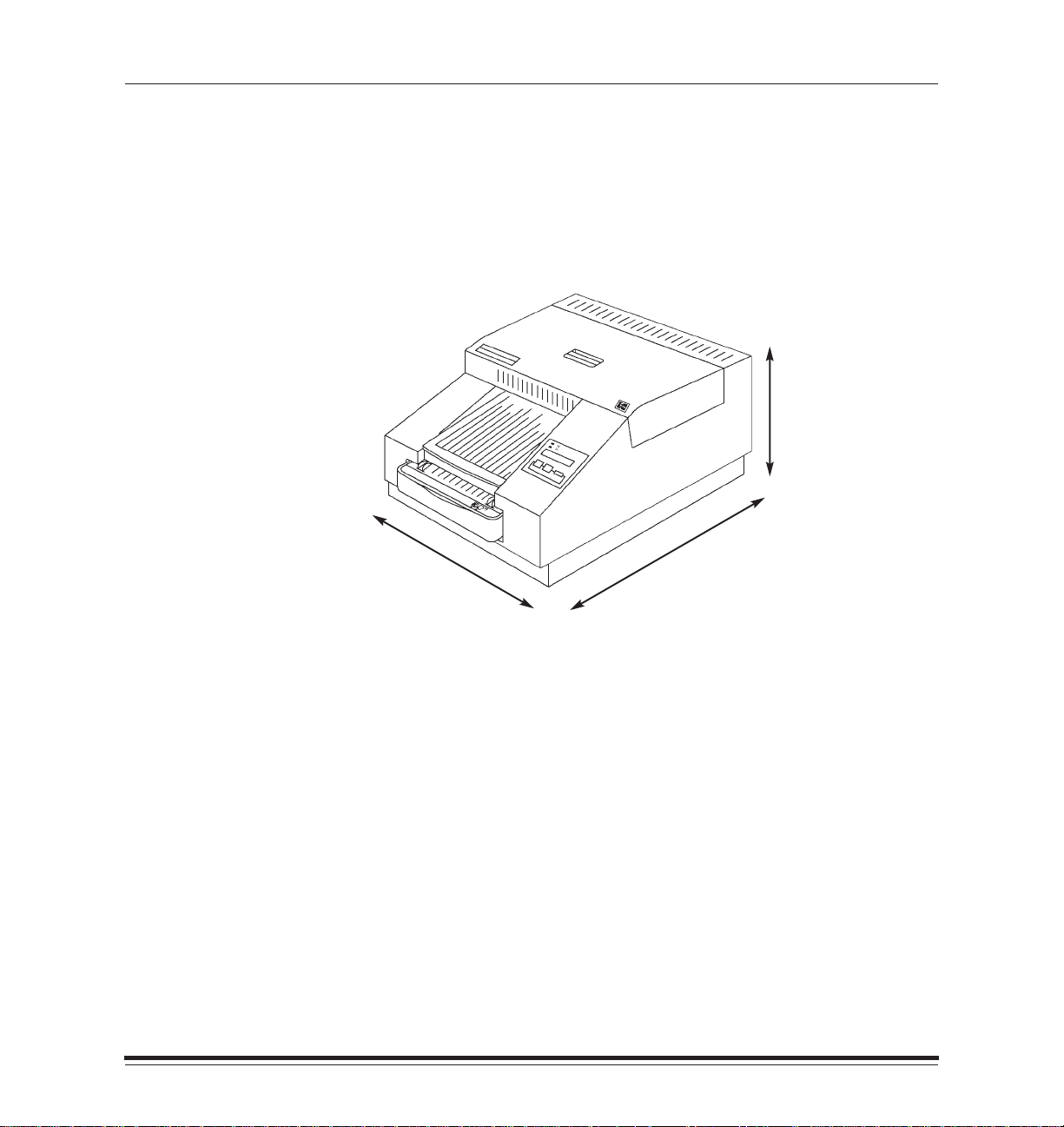
Finding a Location
As you determine the best location for the 8657 Printer, be aware
that certain connections and operations require access behind and on
the side of the printer. You should place the printer so that air flow is not
blocked. The following diagram illustrates the necessary space
requirements.
17I
24I
(plan for 37
to allow room for
removing tray)
1
/2I
12I
(plan for 20
to allow room for
opening cover)
1
/4I
Airborne dirt particles can cause image quality problems. Avoid placing
the printer in areas where ventilation ducts, open doors, or frequent
passers-by might expose the printer and paper to high levels of debris.
NOTE:Allow two (2) inches (about 5 cm) on all sides of the printer for
easy access.
Refer to Appendix A,
Printer Specifications,
for more information about
site requirements.
January 1998
1–3
Page 13
Getting Started
Components of the Printer
The following sections provide instructions for setting up your 8657
Printer.
Reviewing the Components
Familiarize yourself with the printer components in the illustrations and
descriptions that follow.
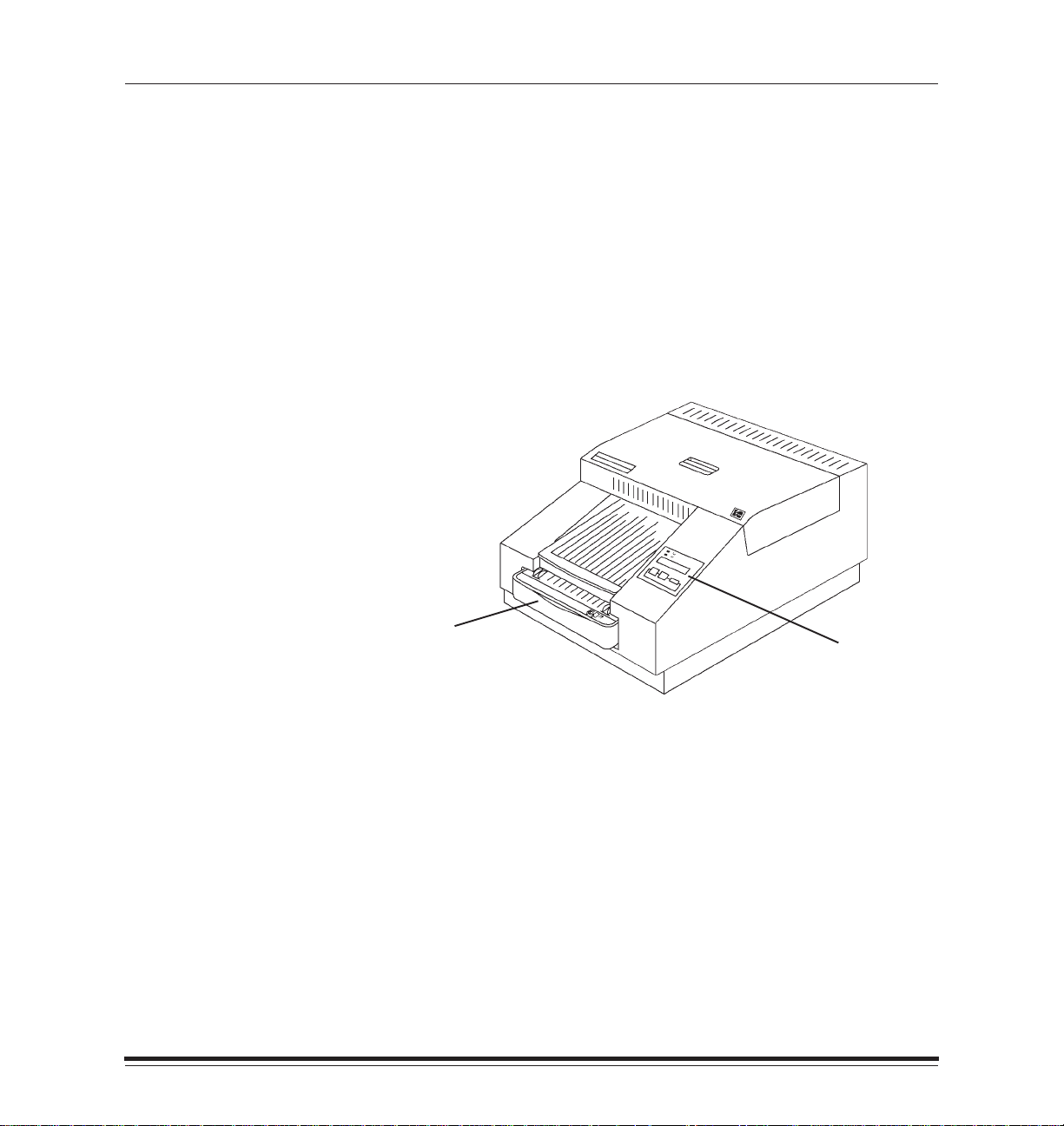
Printer Front View
The components of the printer are shown below.
1–4
paper tray
display panel
Paper tray—the paper tray can hold up to 100 sheets of paper.
January 1998
Page 14
Getting Started
Display panel—the display panel indicates printer status and is
described in detail later in this chapter. You can select the language that
you would like to read on the display panel by using the setup menu.
The following languages are available: English, French, German, Italian,
and Spanish.
January 1998
1–5
Page 15
Getting Started
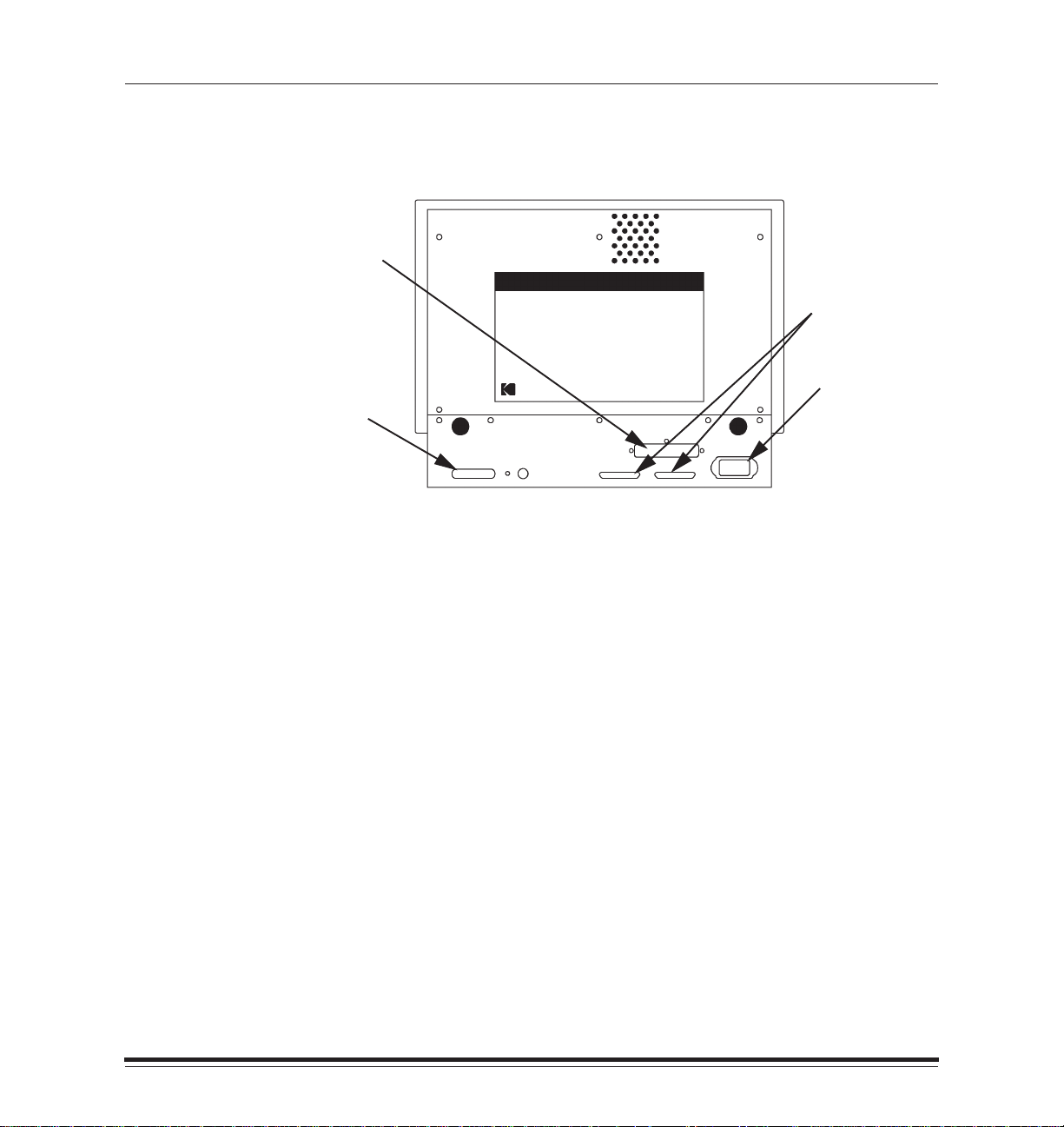
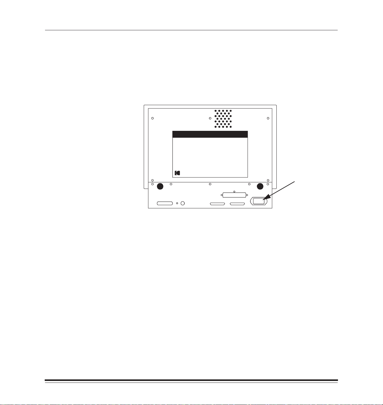
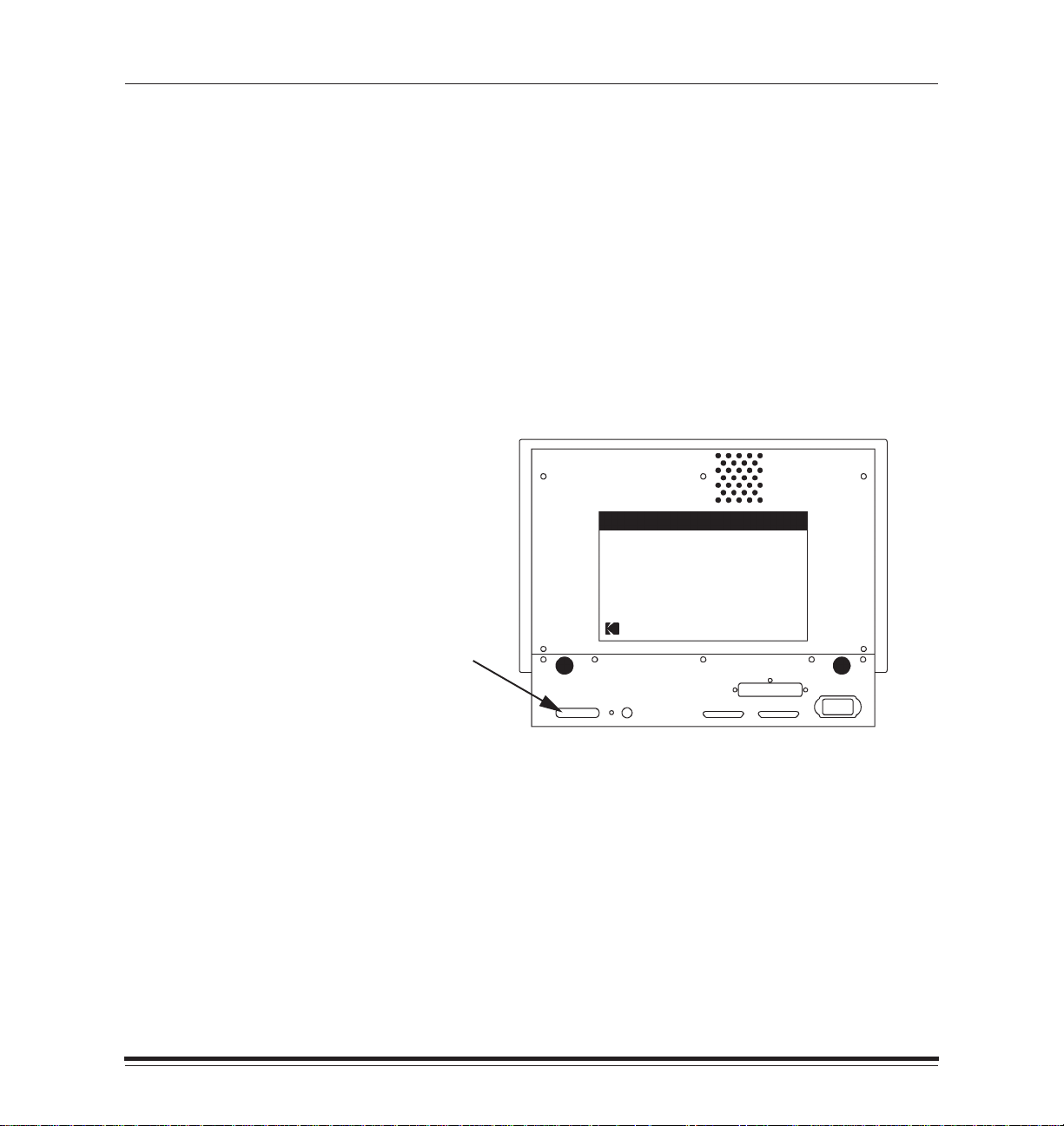
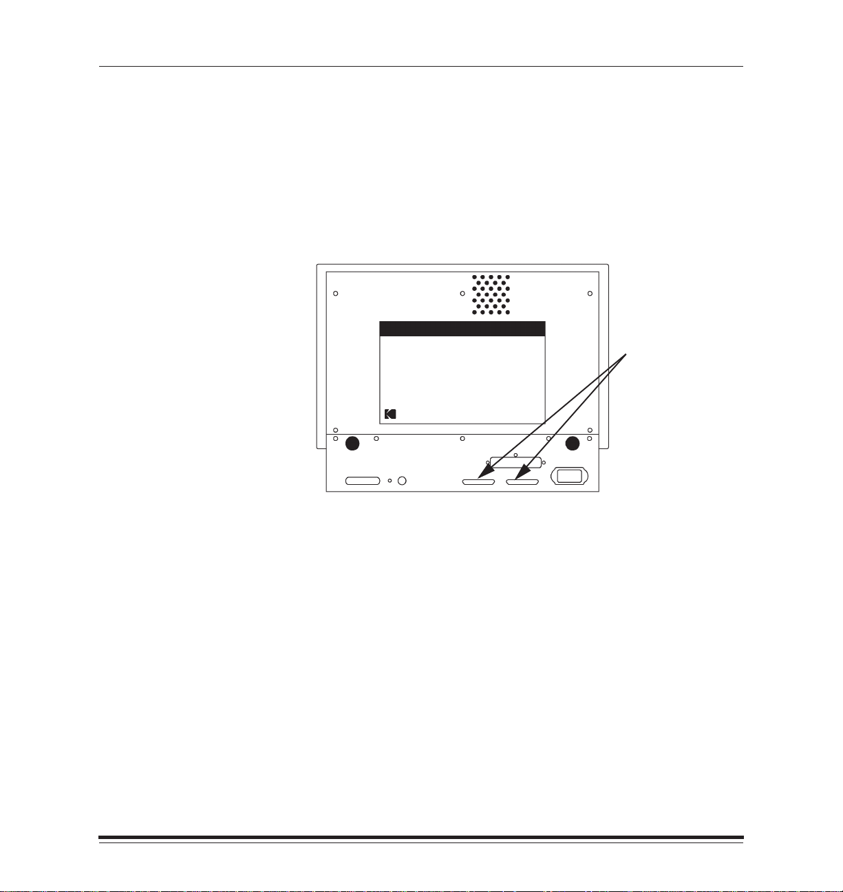
Printer Back View
The back of the printer is shown below.
slot for optional
Network
Interface Card
SCSI ports
power cord inlet
Parallel port
Power cord inlet—one of four standard power cords is included with
your printer. The standard types are for North America/Japan, UK,
Europe Continental, and Australia. If you will be using the printer outside
of these areas, you may need to purchase a power cord.
1–6
Ports—a variety of ports are provided on the back of your printer.
Ethernet ports will be in place if the optional Network Interface Card is
installed.
January 1998
Page 16
Getting Started
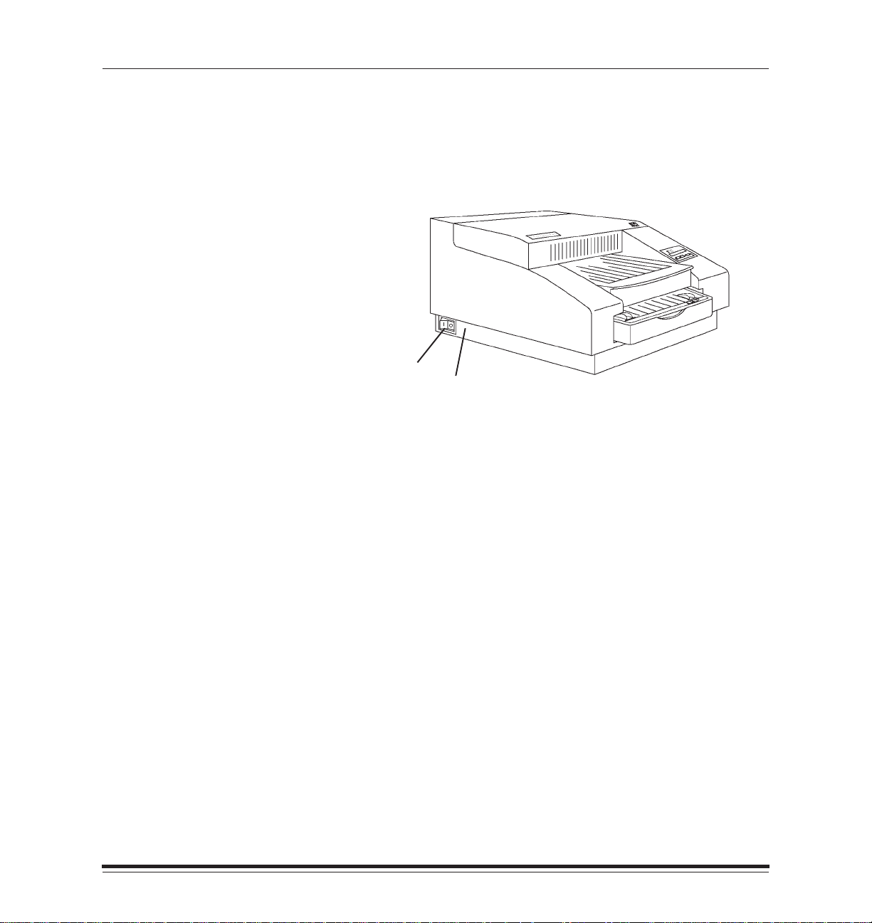
Printer Side View
The side of the printer is shown below.
Power switch—turn the power switch to “I” to turn the printer power on,
or to “O” to turn the power off.
power switch
K number label
K number label—a label next to the power switch displays the printer’s
K number. Provide this number to the technical support group when
contacting Kodak for service.
January 1998
1–7
Page 17
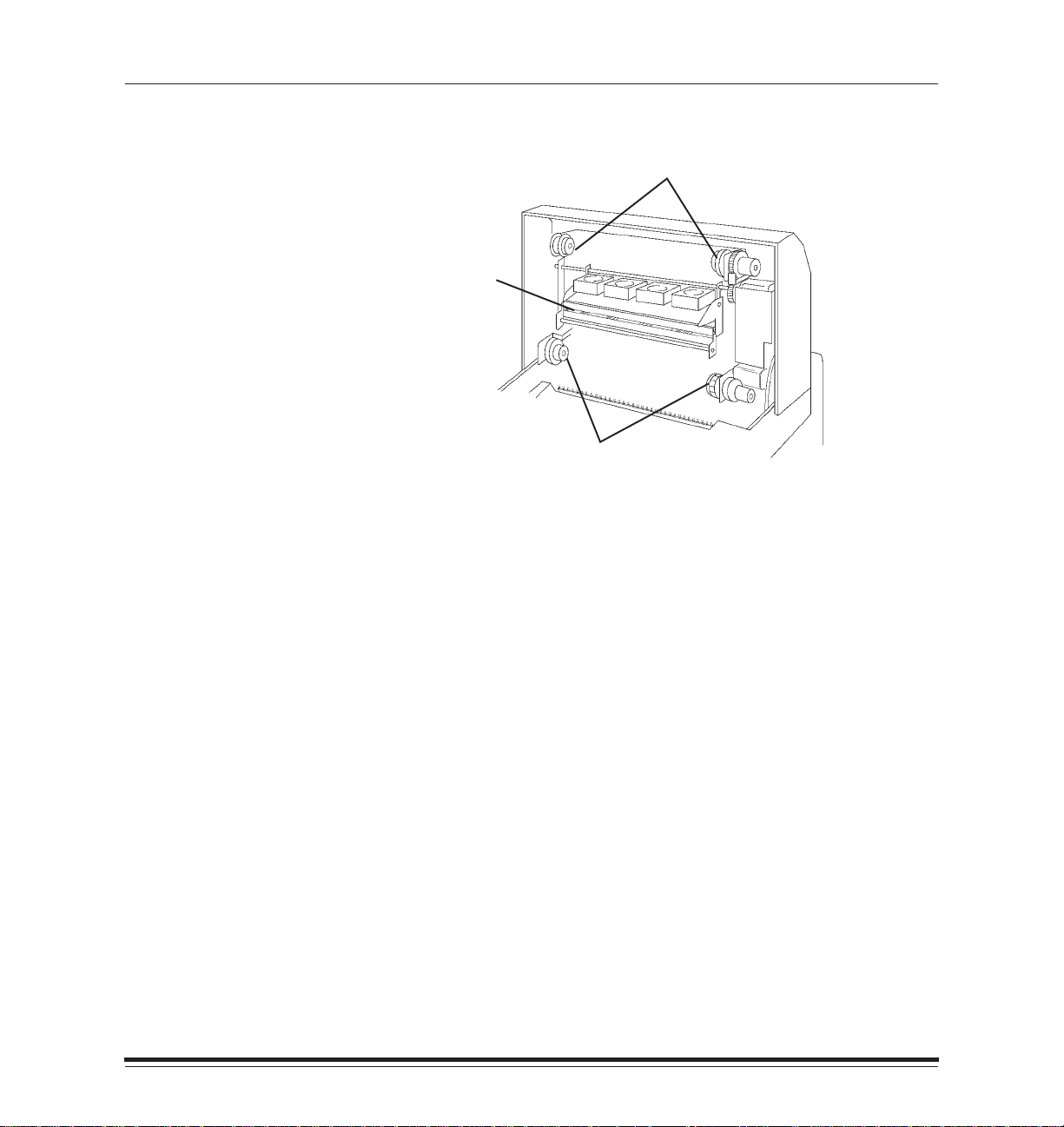
Getting Started
Printer Inside View
takeup spool holders
thermal
head
supply spool holders
Thermal head—the thermal head heats the ribbon to transfer the color
dyes to paper.l
CAUTION:Never rub or wipe anything across the thermal head
except when cleaning it. Refer to the section entitled
“Cleaning the thermal head,” in this chapter for more
information.
1–8
Ribbon spool holders—the ribbon contains dye that creates printed
images. These holders hold the ribbon supply and take-up spools in place.
January 1998
Page 18
Getting Started
Attaching the Power Cord
Follow these instructions to attach the power cord:
1. Make sure that the printer is turned off.
2. Plug the appropriate end of the power cord into the inlet on the back
of the printer.
Power cord inlet
January 1998
3. Plug the other end into an AC outlet.
NOTE:The printer will automatically accept input voltages from 90 to
250V and frequencies from 47 to 60 Hz.
1–9
Page 19
Getting Started
Attaching the Interface Cable
The sections below describe how to attach various cable types. You are
responsible for providing the necessary cable.
NOTE:Ethernet cabling can be used if the optional Network Interface
Card is installed on your printer. Refer to the documentation for
the Network Interface Card for more information.
Centronics Cable (Parallel Connection)
Follow these steps to attach a Centronics cable:
1. Make sure that the printer is turned off.
2. Connect the Centronics cable to the printer’s parallel port.
1–10
Parallel port
3. Connect the other end of the Centronics cable to your computer.
4. Turn the printer on.
January 1998
Page 20
Getting Started
SCSI Cable
Follow these steps to attach a SCSI cable:
NOTE:SCSI cabling can be used only on printers running in raster mode.
1. Make sure that the printer is turned off.
2. Turn the host computer off.
3. Plug in the SCSI cable and secure it to one of the printer’s SCSI ports.
SCSI ports
January 1998
4. Install and secure the SCSI terminator on the open SCSI port or on
the last printer when daisy-chaining multiple printers.
NOTE:If you are connecting the printer to a Macintosh IIfx system, a
special Macintosh IIfx terminator is required. This terminator is
available from your Apple retailer.
5. Turn the printer on.
1–11
Page 21

Getting Started
The following items are required in order to connect your PC to the
printer through a SCSI connection.
An ADAPTEC SCSI host adapter board.
A SCSI terminator
ADAPTEC EZ-SCSI Software. This software is currently provided with
ADAPTEC SCSI host adapter boards when they are purchased. The
supplier of your board should be able to provide the software if you do
not have it.
Refer to Appendix C,
more information.
About SCSI-connected Installations,
for
1–12
January 1998
Page 22
Getting Started
Cleaning the Thermal Head
It is important to clean the printhead when you are installing the printer,
and periodically afterward to remove dust and debris. Dirt can usually be
removed easily by following the head cleaning instructions below.
Clean the printhead each time you replace the ribbon to avoid lines or
streaks in your prints. You may need to clean it more often if your site is
particularly dusty. A cleaning pad is provided with each ribbon spool.
NOTE:If a cleaning pad is not available, use the alternate cleaning
method described in Chapter 4. You can order extra cleaning
pads by contacting Kodak Parts Services at 1–800–431–7278.
The part number for 160 of these pads is TL3127.
1. Turn the printer off.
2. Open the printer cover.
January 1998
3. Remove the ribbon spools carefully if a ribbon is loaded in the printer.
NOTE:When handling thermal ribbon, hold it by the ends of the white plastic
spools. Wearing lint-free gloves is recommended. Fingerprints on the
ribbon web may severely reduce image quality.
1–13
Page 23
Getting Started
4. Stand the ribbon spools on end or set the ribbon on a clean surface so
that dust and dirt are not picked up.
5. Open the cleaning pad.
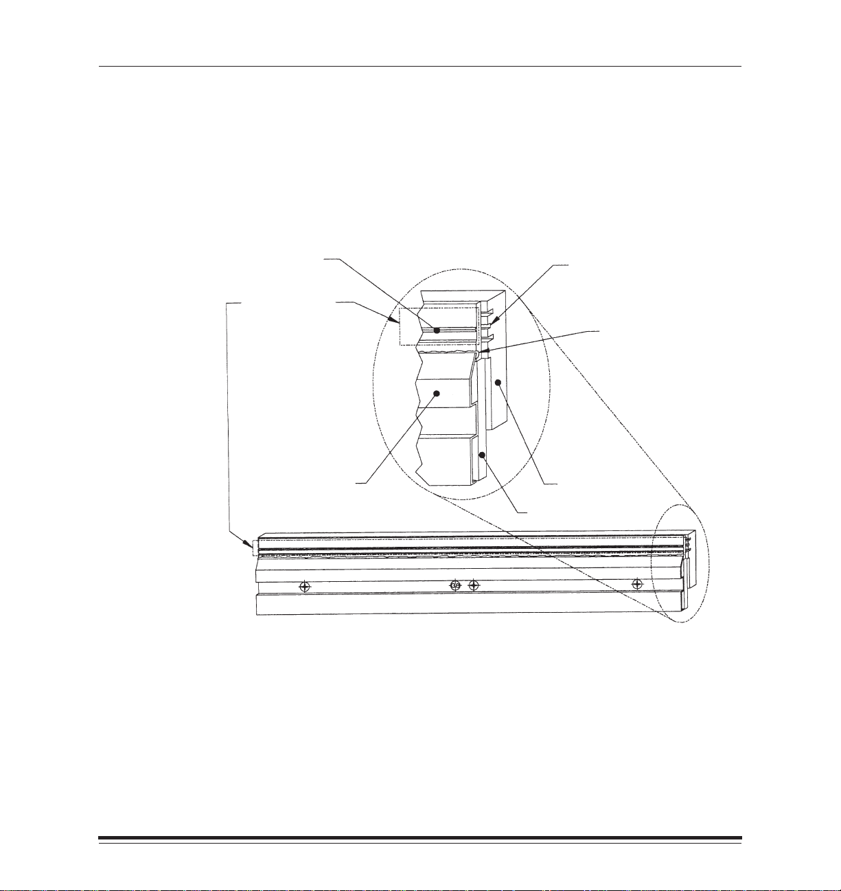
6. Rub the cleaning pad back and forth along the entire length of
the printhead’s heater line which is shown in area A of the
following diagram.
(A) Heater Line
(Bead)
Clean this area
only, along entire
length of Heater
Line. Do not clean
or wipe below this
area, as damage to
the Thermal Head
could result.
(C) Circuit Cover
Center (filled) slot
aligns with Heater Line
when viewed from front.
Sealant Protecting
Circuit Row
DO NOT VIOLATE
(B) Backing Plate
Circuit Board
Thermal Print Head
1–14
The heater line (A) aligns with the center (filled) slot on the backing
plate (B). Be careful not to rub the sealant which protrudes from
beneath the circuit cover (C) as damage to the printhead could occur.
January 1998
Page 24

Getting Started
7. Repeat the back and forth motion several times to insure that the
head is completely clean.
The cleaning pad may become discolored.
8. Wait for the printhead to dry thoroughly before reloading the ribbon.
9. Reload the ribbon spool by following the loading instructions
beginning on page 1–17.
10. Close the printer cover.
11. Turn on the printer.
12. Press the print button on the display panel with paper loaded to make
a test print.
If the printhead was cleaned because of poor image quality and the
quality has not returned to normal, use the alternate cleaning method
described in Chapter 4.
January 1998
1–15
Page 25

Getting Started
Printer Ribbon and Paper
This section describes ribbon and paper, and lists handling instructions
for them.
CAUTION:Use only the materials listed in Chapter 3,
Supplies,
with
the 8657 Printer. Using other materials may cause printer
problems.
About Ribbon
The ribbon provides dyes for printing images.
Color ribbon contains three dye patches; one yellow patch, one magenta
patch, and one cyan patch. Each color ribbon contains enough dye to
generate 200 prints.
Black ribbon contains only black dye patches. Each black ribbon contains
enough dye to generate 150 prints.
XtraLife ribbon (color and black) contains additional patches which
protect images from fingerprints.
Refer to Chapter 3,
ordering ribbon.
Handling
When handling ribbon spools, follow these guidelines:
Hold the ribbon spools by the ends to avoid fingerprints. Lint free
gloves are recommended. Fingerprints on the ribbon web will cause a
severe reduction in image quality.
Supplies,
for more information about storing and
1–16
Don’t remove the tape from the new spool until the spool is mounted in
the printer and the ribbon is ready to attach to the take-up spool.
Store ribbon according to the instructions listed in Chapter 3,
January 1998
Supplies.
Page 26

Getting Started
Loading
The ribbon fits easily in the printer. There is only one way to correctly
place the spools. Follow these steps to insert the ribbon:
NOTE:Wear lint free gloves during this procedure for best results.
1. Remove the old ribbon spools from the printer and dispose of them.
January 1998
NOTE:Images remain on the ribbon after printing. If you are working with
confidential documents, you may want to secure and dispose of
the ribbon accordingly.
2. Clean the thermal head as described in the previous section.
3. Remove the new ribbon spools from the box.
The supply spool is longer than the take-up spool. For new ribbons,
the supply spool will be loaded with ribbon and the take-up spool will
be empty.
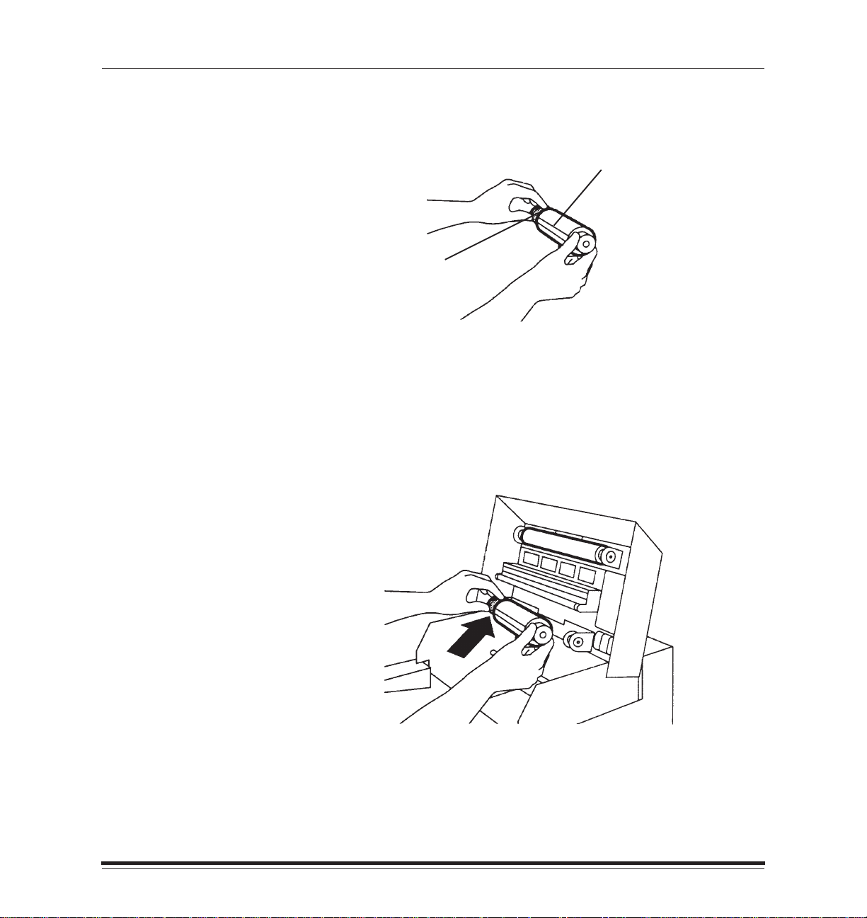
4. Push the left side of the take-up spool into the left side of the top spool
holder (the holders are spring-loaded).
5. Match the notches in the take-up spool with the notches on the right
spool holder.
6. Insert the right side of the take-up spool into the holder on the right.
1–17
Page 27
Getting Started
7. Hold the supply spool so that the adhesive strip on the ribbon is facing
you and the barcode is on the left.
adhesive strip
barcode
8. Make sure that the spool notches are on the right.
This is particularly important when you are reloading a partially used
spool of ribbon.
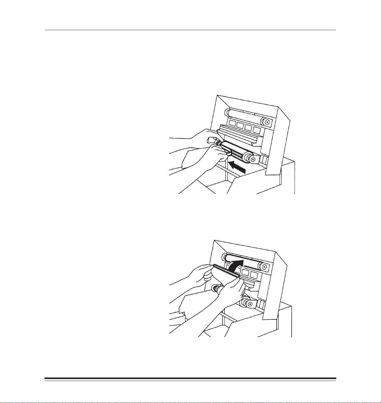
9. Push the left side of the supply spool into the left side of the bottom
spool holder (the holders are spring-loaded).
1–18
January 1998
Page 28
Getting Started
10. Match the notches in the supply spool with the notches on the right
spool holder.
11. Insert the right side of the supply spool into the holder on the right.
12. Remove the tape from the adhesive strip.
January 1998
13. Fold any excess ribbon behind the adhesive strip.
14. Pull the ribbon up carefully and stick the adhesive onto the take-up spool.
1–19
Page 29
Getting Started
NOTE:Keep the ribbon as straight as possible.
15. Smooth the ribbon over the adhesive strip with your fingers.
16. Close the printer cover.
1–20
January 1998
Page 30

Getting Started
About Paper
Thermal paper is available in a variety of sizes. Refer to Chapter 3,
Supplies,
recommendations, and catalog numbers.
The paper looks and feels like photographic paper, but it is not light
sensitive. The back of this paper is printed with a logo to make it easy to
tell which side to put facedown in the tray.
Handling
When handling paper, follow these guidelines:
Hold paper by the edges to avoid fingerprints, which reduce
print quality.
Handle the package of paper with the cardboard stiffener sheets
in place.
Loading
The paper tray adjusts to the size of the paper you want to load. Be sure not
to force paper that is too long or wide into the tray. Follow the instructions
below to adjust the tray to the proper size and to load the paper.
for more information about image sizes, storage
January 1998
NOTE:Although other Kodak paper trays may fit your printer, you should
only use trays designed for the 8657 Printer. Using other trays
may cause paper jams, especially when printing images that
do not take up the maximum image area of the receiver that is
loaded in the tray.
Contact your printer dealer if you need a tray in a size other than
the one supplied with the printer. (Refer to Chapter 3,
Supplies,
for catalog numbers.)
1–21
Page 31

Getting Started
1. Remove the paper tray from the printer.
2. Remove and discard any blue stiffener sheets that remain in the
paper tray.
3. Remove the paper from the package.
NOTE:Handle the paper stack by the edges to avoid fingerprints on the
top page.
4. Remove the blue stiffener sheet from the logo-printed side of the
paper stack.
Leave the other blue stiffener sheet on the bottom of the stack.
5. Place the paper in the tray with the logo side facing up.
1–22
January 1998
Page 32

Getting Started
6. Press the latches on the front sides of the paper tray into place.
7. Insert the paper tray in the printer until it locks into position.
January 1998
8. Verify that the correct paper size is listed on the display panel.
1–23
Page 33

Getting Started
Turning on the Power
Press the “|” side of the power switch to turn on the printer. The switch is
located on the lower left side of the printer.
It may take up to one minute for the printer to initialize. During this time,
the power light will illuminate, and two messages will display alternately
on the display panel:
INITIALIZING*
INITIALIZING**
PLEASE WAIT
1–24
When the printer is ready a set of three messages will flash on the
display panel:
READY–raster
ribbon type
.
media type
in the paper tray.
ribbon type
printer. For example, “XTRALIFE COLOR”.
If the printer fails to initialize, the following message will appear on the
control panel:
If this message appears, turn the printer off and back on again. If the
message appears again, the printer requires service.
will be replaced by the size and type of paper that is loaded
will be replaced by the type of ribbon that is loaded in the
INIT ERROR
January 1998
Page 34

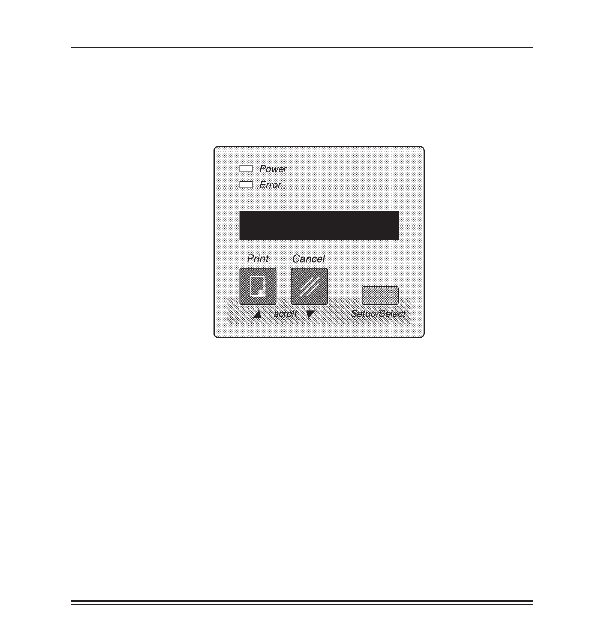
Understanding the Display Panel
Familiarize yourself with the display panel shown below.
Getting Started
January 1998
A description of each item is on the following pages.
1–25
Page 35

Getting Started
Indicator Lights
The indicator lights on the display panel illuminate according to the status
of the printer. There are two indicator lights:
Power
The Power light indicates that the printer is turned on.
Error
The Error light indicates that there is an error condition. When this light is
lit, a message will be displayed. There are two types of error conditions:
user-correctable errors and errors requiring service.
User-correctable error—when the error light is lit but is not flashing, you
can correct the problem yourself. The light will stay on until you have
responded to all messages displayed in the LCD panel.
Service call error—when the error light flashes, a system error message
will be displayed on the LCD panel. Turn the printer off and then on
again. If the error continues, service is required.
1–26
January 1998
Page 36

Getting Started
LCD Panel
The LCD (Liquid Crystal Display) panel displays one 16-character line at
a time. Messages longer than 16 characters are broken into 16-character
sections and are alternated in the display.
The LCD panel displays messages on the current status of the printer.
Job-related messages refer to the status of the job closest to completion.
Media-related messages indicate the type of paper and ribbon that are
loaded in the printer. Messages also appear when the paper tray is
empty, when the printer’s cover is open, or when errors occur.
Messages
The printer’s display panel provides information about the status of the
printer. The information that appears depends on the current state of
the printer.
The following status information is displayed when the printer is idle.
Emulation—this part of the message displays RASTER.
Media—this part of the message displays the size of the paper that is
loaded in the paper tray.
January 1998
Ribbon—this part of the message displays the type of ribbon that is
loaded in the printer.
Status information is returned to the computers which send files to the
printer. Refer to Chapter 4,
software documentation for more information.
Correcting problems,
and to the printing
1–27
Page 37

Getting Started
Buttons
The buttons on the display panel allow you to set the printing features of
the printer, cancel print jobs, override mismatches, and generate test
prints. Following are descriptions of each button.
Cancel
The Cancel button allows you to abort the job that is closest to completion.
For example, you may have a job printing and a job processing. If you
press the Cancel button, the job being printed is aborted immediately. No
additional pages in that job are printed, and the page that is currently
being printed is ejected. If you press the Cancel button again, the next
job will be cancelled, if one exists.
The Cancel button also scrolls down through the Setup menu when using
the Setup button. For more information, refer to the section entitled
“Printer Setup” in this chapter.
Setup/Select
The Setup/Select button allows you to enter the Setup mode to control
printer parameters. See the section entitled “Printer Setup” in this chapter
for more details.
1–28
Print
The Print button:
Generates a test print when the printer is not processing other jobs
and READY appears in the LCD panel.
Begins printing after mismatch errors are listed. For more
information, refer to the section “Mismatch Conditions” in
Chapter 4,
Correcting Problems.
January 1998
Page 38

Getting Started
Configuring the Printer
A number of printer configuration parameters must be established by
using the Setup/Select button on the display panel. The Setup program
includes a list of menus and submenus that you can access and
manipulate by using the Setup/Select, Print, and Cancel buttons.
Using Setup Menus
Entering Setup Mode
Press the Setup/Select button while the printer is in the READY state to
enter the Setup mode. The first option you will see is SETUP:EXIT.
Selecting Options
You can scroll up through the list of setup features by pressing the Print
button, or down through the list by pressing the Cancel button. The
scrolling feature takes you through the options in a loop; it is not
necessary to scroll up to get to SETUP:EXIT.
When you find the desired option in the submenu, press the Setup/Select
button to select that option.
January 1998
An asterisk (*) to the right of an option on the display panel indicates that
the option is currently selected on your printer. In the descriptions that
follow, options marked with asterisks (*) are factory settings.
Exiting Setup Mode
Select the SETUP:EXIT option to leave Setup mode.
1–29
Page 39

Getting Started
Selecting a Language for the Display Panel
Press the Setup/Select button when SETUP:LANGUAGE appears in the
display panel. You can choose from the following languages:
LANG:ENGLISH*
LANG:ESPANOL
LANG:FRANCAIS
LANG:DEUTSCH
LANG:ITALIANO
LANG:EXIT
Use the Print and Cancel buttons to scroll through the list. Press
the Setup/Select button to make your choice. The change takes
place immediately .
Select LANG:EXIT once you have made your selection.
Selecting Defaults
Press the Setup/Select button when SETUP:DEFAULTS appears in the
display panel to change the printer’s default settings.
Restoring Factory Settings
Use the DEFAULTS:FACTORY menu to return all option settings to those
that were in place when the printer was installed.
FACTORY:RESET
FACTORY:EXIT
Select FACTORY:RESET to restore all operating parameters to the
factory settings. The printer will reboot immediately so that the new
options will be in place.
Select FACTORY:EXIT when you are done.
1–30
January 1998
Page 40

Getting Started
Specifying Port Information
Use the SETUP:PORTS menu to change the default port information.
Press the Setup/Select button to get into the SETUP:PORTS submenu.
The options you select must match your host computer settings.
NOTE:The submenus that appear for this menu depend on whether the
Network Interface Card is installed in the printer.
Setting up a Parallel Connection
Use the PORTS:PARALLEL menu to establish information about
connecting the printer through a parallel port. The new option will be in
place once you exit Setup mode.
PARA:MODE—This menu specifies whether the parallel port should
accept data in normal PostScript mode or in Adobe binary mode. Normal
PostScript mode can only support printable characters; it does not accept
characters in the high ASCII range (128–255). Adobe binary mode
supports the high ASCII range. Full 8-bit data may be sent.
The following settings are available.
MODE:NORMAL*
MODE:BINARY
MODE:EXIT
January 1998
Select MODE:EXIT once you have made your selection, and PARA:EXIT
when you are done.
1–31
Page 41

Getting Started
Setting up an EtherTalk Connection
Use the PORTS:ETHERTALK menu to establish information about
connecting the printer through an EtherTalk connection. The new option
will be in place once you exit Setup mode. The only options available in
this submenu are E–TALK:VERSION and E–TALK:EXIT.
NOTE:This menu option will appear only if the Network Interface Card is
installed in the printer.
E–TALK:VERSION—This menu specifies whether version 1 or 2 of
AppleTalk will be used on the EtherTalk connection. The following
settings are available.
VER:2*
VER:1
VER:EXIT
Select VER:EXIT once you have made your selection, and E–TALK:EXIT
when you are done.
Setting up an IPX (Novell NetWare) Connection
Use the PORTS:IPX menu to establish the framing type the printer should
expect. The new option will be in place once you exit Setup mode.
1–32
NOTE:This menu option will appear only if the Network Interface Card is
installed in the printer.
The following settings are available.
IPX:802.3
IPX:802.2
IPX:SNAP
IPX:ETHERNET 2
IPX:AUTOSELECT*
IPX:EXIT
Select IPX:EXIT when you are done.
January 1998
Page 42

Getting Started
Setting up a TCP/IP Connection
Use the PORTS:TCP/IP menu to establish the internet address of the
printer within a TCP/IP network. The address will be in place once you
exit Setup mode.
NOTE:This menu option will appear only if the Network Interface Card is
installed in the printer.
The following settings are available.
TCP/IP:ADDRESS
TCP/IP:EXIT
Select TCP/IP:ADDRESS to access a screen which allows you to enter
digits for the address. The address is represented as four groups of 3
digits each, separated by periods. (For example, nnn.nnn.nnn.nnn). The
cursor will be positioned in the left-most digit. Press the up arrow button
to increment the number in that position by one. Press the down arrow
button to move the cursor to the next digit to the right. Press Select to
accept the address and exit the screen.
Select TCP/IP:EXIT when you are done.
January 1998
1–33
Page 43

Getting Started
Setting up a SCSI Connection
Use the PORTS:SCSI menu to change the SCSI port address.
The following addresses are available.
SCSI:ADDRESS0
SCSI:ADDRESS1
SCSI:ADDRESS2
SCSI:ADDRESS3
SCSI:ADDRESS4
SCSI:ADDRESS5*
SCSI:ADDRESS6
SCSI:ADDRESS7
SCSI:EXIT
The new option will be in place once you exit Setup mode.
Select SCSI:EXIT when you are done.
1–34
January 1998
Page 44

Getting Started
Making a Test Print
The 8657 Printer can print a test page without needing a file to be sent
from a computer. The test image helps you verify proper setup and
printer operation, and confirm print quality.
You should make a test print after installing the printer to check
print quality.
To make a test print, follow these steps:
1. Make sure that READY appears on the display panel.
2. Press the Print button on the display panel.
While image data is processing, the following message will appear on
the display panel:
PROCESSING:
TEST PRINT
Once the image data is processed, the following message will be
displayed:
PRINTING
January 1998
As printing takes place, the printer moves the paper through the imaging
path multiple times. During this process, the paper will partially exit the
printer. Do not pull on the print during any of the passes. Wait until the
print exits completely before touching it.
1–35
Page 45

Getting Started
Printing
While image data is processing, the following message will appear on the
display panel:
PROCESSING
Once the image data is processed, the following message will be
displayed:
PRINTING
If you press the Cancel button while the printer is processing or printing a
job, the following message will be displayed:
CANCELLING JOB
As printing takes place, the printer moves the paper through the imaging
path multiple times. During this process, the paper will partially exit the
printer. Do not pull on the print during any of the passes. Wait until the
print exits completely before touching it.
NOTE:The last image that is sent will remain in the printer’s memory
until the printer is turned off.
1–36
January 1998
Page 46

Getting Started
Job Scheduling
The number of jobs that can be queued to the printer at one time
depends on the available memory in the printer. If large image files are
sent, fewer jobs can be processed. Installing optional memory in the
printer increases the number of jobs that can be processed concurrently,
and is described in Appendix B.
The other factor that impacts job scheduling is the network configuration
in which the printer is installed. When the printer is connected through
more than one port, the printer polls the ports in a round robin manner.
This means that once a job is received by the printer, it stops polling the
ports until the job has finished printing. When the job is complete, the
printer then looks to the next port in the list. The position of the ports in
the list therefore impacts the order in which jobs are processed. Timing of
when jobs are sent is not not the sole determinant of when jobs will be
processed and printed.
January 1998
1–37
Page 47

Getting Started
Storing Prints
The image stability of thermal prints depends on factors such as
temperature, relative humidity, and exposure to light or to biological or
chemical contaminates. Using XtraLife ribbon when printing increases
the shelf life of prints. Thermal prints should be stored in a cool, dry
environment that is free of chemical contamination.
D The lower the temperature the better. Avoid temperatures higher than
72_F (25_C) for extended periods.
D A relative humidity between 30% and 50% is ideal.
D Avoid exposure to high-intensity light sources, particularly florescent
light and sunlight which are rich in ultraviolet radiation.
D Avoid exposure to vinyl items (those made of polyvinyl chloride [PVC])
or any plastic which contains plasticizer. These items usually have a
distinctive “plastic” odor.
Your thermal images will last for a long time if you store them as
described above.
1–38
January 1998
Page 48

2 Maintaining the Printer
A clean and dust-free environment is recommended when using the
8657 Printer.
Keep the printer clean and the surrounding area vacuumed and
litter-free.
Do not expose the printer to tobacco smoke or liquid spills.
Do not place objects on top of the printer.
The major enemy of good printer performance and high-quality output is
dirt. Perform the following preventive maintenance periodically.
Clean the thermal head each time you load a new ribbon or if you
notice image quality problems.
Refer to the thermal head cleaning procedure detailed in Chapter 1,
Getting Started.
Clean the roller bar.
Clean the paper tray area, paper exit area, and printer cabinet with a
damp, lint-free cloth. This eliminates dust buildup and prevents dirt
from getting in the printer.
January 1998
CAUTION:Always turn the printer off and unplug it before cleaning.
Never use abrasives or harsh chemicals to clean any part
of the printer. Do not use thermal head cleaning pads to
clean the printer cabinet.
Clean the area around and under the printer to keep dust out of the
cooling fan on the bottom. Do not put paper under the printer because
it can block the fan.
2–1
Page 49

3 Supplies and Accessories
This chapter describes how to order and store supplies.
Ordering Supplies and Accessories
The following products can be ordered by contacting Kodak Parts
Services at 1–800–431–7278.
Product Part Number
Water Cleaning Pads (box of 50) 5B4801
Paper Tray (7.0 x 8.5”) 4B0330
Pick Roller Cleaning Kit 5B5910
Shipping Pins 989021
The following products can be purchased through your printer dealer or
distributor.
Product
KODAK PROFESSIONAL EKTATHERM Medium
Format Ribbon
KODAK Network Interface Card 856 3678
Catalog
Number
837 0470
January 1998
3–1
Page 50

Supplies
Paper
The table below lists the paper size and catalog number. The maximum
image size that can print on the page is also illustrated. Paper can be
purchased through your printer dealer or distributor.
NOTE:Paper is shipped in packages of 100 sheets.
Catalog
Paper Type
KODAK PROFESSIONAL EKTA THERM Paper
7.0 x 8.5 I
179 x 217mm
Image area:
80x5I
8.0 x 5
217 x 127mm
Number
834 5811
3–2
January 1998
Page 51

Storing Supplies
Always keep your work area and material storage area as clean
as possible.
Ribbon
For highest image quality, follow these ribbon storage instructions:
D Store unopened ribbon at temperatures below 77_F (25_C).
Avoid exposure to temperatures higher than 100_F (38_C).
D Wrap partially used ribbons in their original wrappers to protect them
from dust and dirt when they are not loaded in the printer. Dust and dirt
specs on the ribbon show up as much larger spots on prints. When
handling the ribbons, hold the spools only by the ends. Lint free gloves
are recommended.
D Do not expose the ribbon to direct sunlight, extreme heat, dust,
or liquids.
D Leave the printer cover closed except when you need to access the
inside of the printer.
Refer to the storage instructions on the package for more information.
Supplies
January 1998
3–3
Page 52

Supplies
Paper
For highest image quality, follow these paper storage instructions:
D Store opened paper at temperatures below 77_F (25_C). Avoid
exposure to temperatures higher than 100_F (38_C).
D Relative humidity level for storing and using paper should be between
40% and 60%. Relative humidity lower than 20% or higher than 76%
should be avoided even for short periods of time. Print paper can
tolerate a relative humidity between 20% and 40% and between 60%
and 76% for up to a few hours without causing the paper to curl.
High relative humidity tends to cause paper to curl toward the image
side of the paper. Low relative humidity tends to cause paper to curl
away from the image side of the paper. Low relative humidity also
tends to increase static attraction of dust and dirt.
D Keep the bottom stiffener board in place when handling stacks of
paper to avoid fingerprints on the printing surface.
D Avoid storing loose stacks of paper out of its wrapper.
D Do not use wet or damaged stock.
3–4
D Keep the lid on the paper tray and the paper tray inserted in the printer
to protect the paper from exposure to light and dust or dirt.
If you experience humidity-related paper problems, refer to Chapter 4,
Correcting problems,
for additional storage recommendations.
January 1998
Page 53

4 Correcting Problems
Understanding Error Messages
Error messages are displayed on the printer display panel. High priority
events or states are displayed before lower priority ones. It is possible
that more than one error can occur at the same time; however, the panel
can display only one error at a time. You must resolve the problems in
the order that they appear on the panel. For example, a CLOSE COVER
message may appear. After you close the printer cover, a paper
mismatch message may appear. After you fix the paper mismatch
problem, and if there are no other errors, READY will be displayed.
Following is an alphabetical list of the most common error messages that
appear on the printer’s LCD display.
CHANGE RIBBON
The printer is unable to advance the ribbon because the supply spool is
empty or the ribbon’s barcode cannot be read. Open the cover and
change the ribbon, or check to see if the barcode is legible. Refer to
Chapter 1,
CHECK TRA Y
The printer senses a paper jam in the tray area, the tray is not seated
properly, or the tray is empty. Remove the tray, clear the area or add
paper, and reinsert the tray.
Getting Started,
for ribbon loading instructions.
January 1998
CLEAR P APER PATH
The printer finds paper in the paper path and cannot clear it. Open the
printer cover, clear the path, and close the cover. Refer to the “Clearing
the Paper Path” section in this chapter for instructions.
4–1
Page 54

Correcting Problems
CLEAR RIBBON JAM
The printer senses that ribbon is jammed. Open the printer cover, clear
the jam, and close the cover.
CLOSE COVER
The printer cover is open. Close it to make the printer ready.
INIT ERROR
The printer failed to initialize. Restart the printer. If the message is still
displayed, service is required.
INSERT TRAY
The printer senses that the paper tray is not it place. Insert the paper tray
to make the printer ready.
LOAD P APER
(
Paper Size)
The printer senses that the tray is empty. The message specifies the
requested paper size.
LOAD RIBBON
(
Ribbon Type)
4–2
The printer checks the ribbon’s barcode and detects that the ribbon type
that is loaded does not match the requested ribbon type. Open the cover
and load the correct ribbon. The message specifies the requested ribbon
type.
SERVICE REQ
XXX
The printer detects an error. The message includes a 4-digit error code.
Restart the printer. If the message is still displayed, service is required.
January 1998
Page 55

Correcting Problems
Ribbon Type Mismatch
If you send a print job from a computer and request a ribbon type that is
not currently loaded in the printer, you will be notified of a mismatch.
There are two ribbon-mismatch situations:
Mismatches due to lamination differences (for example, you request
XltraLife ribbon in your job but it is not loaded). For these situations,
you can press the Print button and the job will print with the ribbon that
is currently loaded.
Mismatches due to ribbon color differences (for example, if black-only
printing is requested but a color ribbon is loaded). For these situations,
you must change the ribbon or press Cancel to cancel the job.
January 1998
4–3
Page 56

Correcting Problems
Troubleshooting
Before requesting service, you may be able to identify or correct
problems yourself. Make a test print, and then use the following chart to
find quick solutions to some general printer problems. If you can’t resolve
the situation, refer to the “Getting Additional Help” section at the end of
this chapter.
Symptom
Possible solution(s)
Printer does not power up. Make sure the power switch is
in the “I” position.
Make sure all cables and cords
are plugged in properly.
Printer does not initialize. 1. Turn off the printer and the
host computer.
2. Disconnect the interface
cable from the printer.
3. Turn both machines back on
again.
4. Reconnect the interface cable
to the printer.
Printing takes significantly more
time than usual.
Image file size may be larger
than usual and may therefore
take longer to process.
Reduce the room temperature
or turn the printer off for ten
minutes to let it cool.
4–4
January 1998
Page 57

Symptom Possible solution(s)
Printer does not print when job is
sent from the host.
Streaks, lines, or spots appear
on prints.
Correcting Problems
Wait to see if the job is still
processing.
Try printing a file that has
printed previously.
Verify all export module or
printer driver settings.
Check communications settings
for compatibility between printer
and host.
Follow instructions for “Printer
does not initialize.”
Disconnect the communications
cable from the back of the
printer and try a test print.
If this does not work, service
is required.
Check to see that the paper in
the tray is clean and free of
streaks.
January 1998
Check to see if the ribbon
is clean.
Clean the thermal head per the
instructions in
Getting Started.
If streaks persist, use the
alternate procedure described
in this chapter.
4–5
Page 58

Correcting Problems
Symptom Possible solution(s)
Multicolored spots appear
on prints.
Clean the printer and the area
around it.
Move printer away from
ventilation ducts or open doors.
Printer initializes, but does not
enter the READY state.
Disconnect and reconnect the
interface cable to the printer.
Restart the printer. If the
problem persists, service
is required.
Paper will not feed. Look at the paper and
remove any from the stack
that have irregularities.
Reduce the size of the stack of
paper in the paper tray.
Make sure that the blue stiffener
sheet is at the bottom of the
paper tray.
4–6
January 1998
Page 59

Correcting Problems
Symptom Possible solution(s)
No printer response when
buttons are pressed.
You may have pressed invalid
buttons.
1. Make sure the printer cover is
closed.
2. Reinsert the paper tray.
3. Restart the printer.
4. Make sure the printer is in
READY mode.
Display panel says CHANGE
RIBBON, but the correct ribbon
is loaded and the supply spool is
Open the printer cover and
check to see if the barcode on
the ribbon is legible.
not empty.
Check to see if the ribbon
is jammed.
Display panel says CHECK
TRAY, but tray is not empty.
Display panel says LOAD
RIBBON, but ribbon is already
loaded.
Open the printer cover, remove
tray, and inspect for paper jam.
The requested ribbon is not
loaded in the printer.
Open the printer cover and load
the requested ribbon.
Dirt appears on prints. Make a test print to clean out
remaining debris.
January 1998
Clean the thermal head per the
instructions in
Getting Started.
streaks persist, use the
alternate procedure described
in this chapter.
If
4–7
Page 60

Correcting Problems
Handling for Humidity-related Paper Problems
If paper shows signs of exposure to humidity levels outside the
recommended range as described in Chapter 3,
be taken to help protect it.
Keep small amounts of paper loaded in the printer rather than loading
a whole package. Paper stored in the wrapper lasts longer.
Wrap partial stacks of paper in its original plastic wrap, squeeze out
the air, and tape the wrap shut. This will protect the paper from
humidity and from dust or dirt. Dust and dirt specs on the paper show
up as much larger spots on prints.
Avoid leaving paper in the printer overnight or on weekends.
If the problems persist, you should consider installing a humidifier or
dehumidifier to bring the humidity in your environment within the
acceptable range.
Supplies,
extra care can
4–8
January 1998
Page 61

Correcting Problems
Alternate Head Cleaning Instructions
Small particles of dust or debris may stick to the printhead, causing lines
or streaks to appear in your prints. These particles can usually be
removed easily by following the head cleaning instructions in Chapter 1,
Getting Started.
The following procedure may be used to remove more stubborn debris,
or when you do not have a cleaning pad.
NOTE:Refer to Chapter 3,
cleaning pads.
1. Turn the printer off.
2. Open the printer cover.
3. Remove the ribbon spools carefully if a ribbon is loaded.
NOTE:When handling the thermal ribbon, hold it by the ends of the white
plastic spools. Wear lint-free gloves for best results. Fingerprints
on the ribbon web may severely reduce image quality.
4. Stand the ribbon spools on end, or set the ribbon on a clean surface
so that dust and dirt are not picked up.
5. Dampen a clean, lint-free, soft cotton cloth slightly with distilled water.
Make sure that the cloth is not dripping wet.
NOTE:Do not use cotton or cotton blends because they shed lint
particles. 100% polyester or nylon fabrics work well.
Supplies,
for information about ordering extra
January 1998
4–9
Page 62

Correcting Problems
6. Rub the cloth back and forth along the entire length of the printhead’s
heater line which is shown in area A of the following diagram.
(A) Heater Line
(Bead)
Clean this area
only, along entire
length of Heater
Line. Do not clean
or wipe below this
area, as damage to
the Thermal Head
could result.
(C) Circuit Cover
Center (filled) slot
aligns with Heater Line
when viewed from front.
Sealant Protecting
Circuit Row
DO NOT VIOLATE
(B) Backing Plate
Circuit Board
Thermal Print Head
4–10
The heater line (A) aligns with the center (filled) slot on the backing
plate (B). Be careful not to rub the sealant which protrudes from
beneath the circuit cover (C) as damage to the printhead could occur.
January 1998
Page 63

Correcting Problems
7. Repeat the back and forth motion several times to insure that the
head is completely clean. Press harder if necessary.
8. Repeat steps 6 and 7 if you have a cleaning pad.
9. Wait for the printhead to dry thoroughly before reloading the ribbon.
CAUTION:Since water is used in this procedure drying time is
longer than when using a head cleaning pad. Make sure
that you let the printhead dry completely.
10. Reload the ribbon spool once the printhead is completely dry by
following the instructions beginning on page 1–17.
11. Close the printer cover.
12. Turn on the printer.
13. Make two
test prints on paper.
If you have trouble finding a piece of debris that continues to cause print
problems after cleaning, hold one of the streaked prints up to the head to
give you a better idea of where the particle is located.
January 1998
4–11
Page 64

Correcting Problems
Clearing the Paper Path
Paper may occasionally get caught in the printer. Jams are typically
identified by a CLEAR PAPER P ATH or CHECK TRAY message on the
display. Follow these steps to clear the paper path.
1. Open the printer cover.
4–12
NOTE:If you can’t open the cover, restart the printer by turning it off and
on. There is a mechanical interlock to prevent you from opening
the door while printing. If after restarting the printer, you still can’t
open the cover, service is required.
January 1998
Page 65

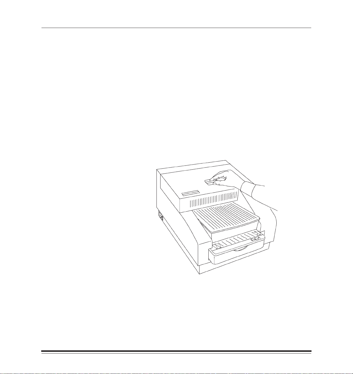
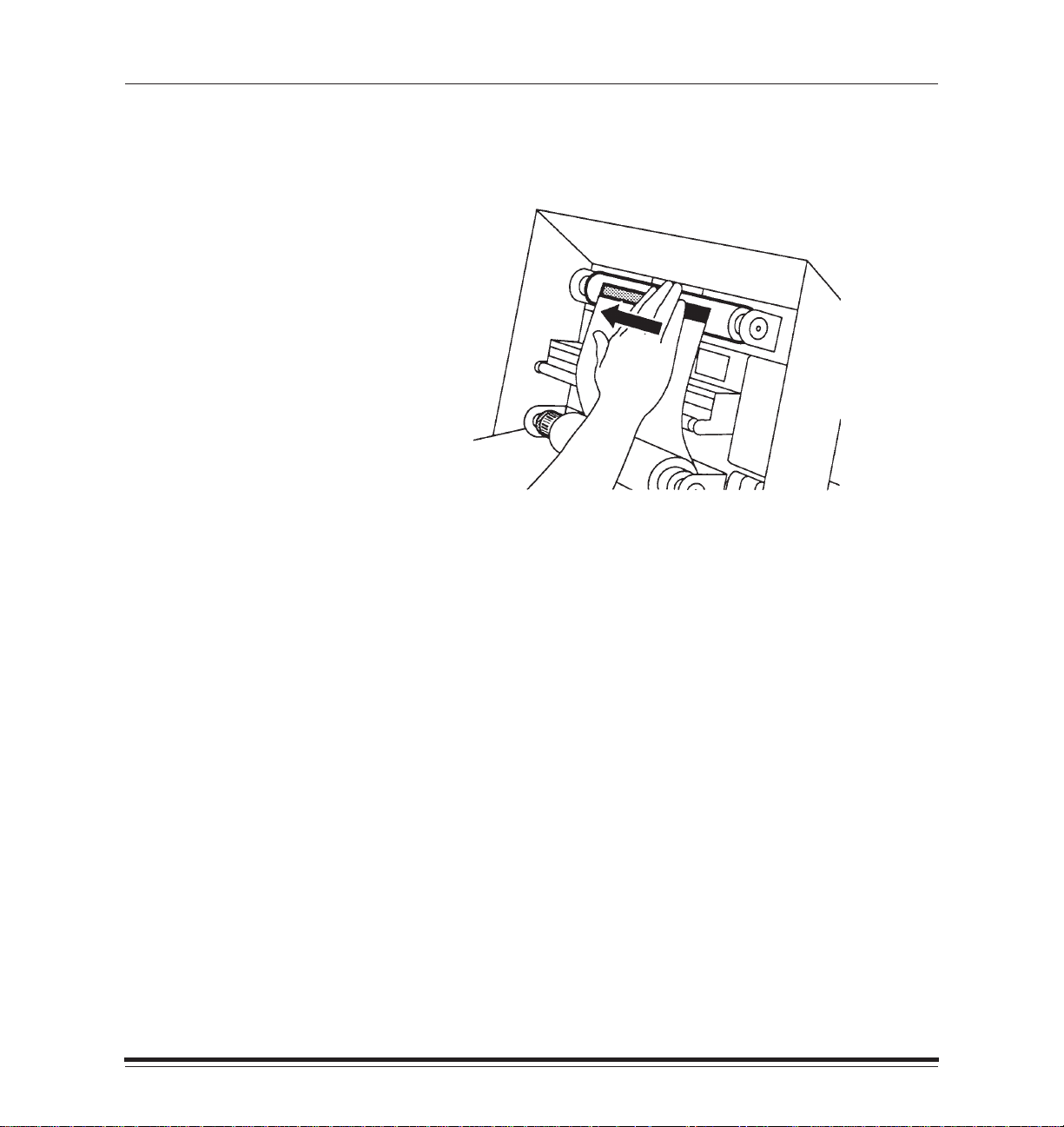
2. Gently pull paper up if it is caught inside the printer.
Power
Error
Correcting Problems
January 1998
3. Remove the paper tray if the paper is caught in the paper tray area.
4–13
Page 66

Correcting Problems
4. Look in the tray area through the tray insertion slot.
5. Reach inside the paper tray area and gently pull the jammed
paper out.
Power
Error
NOTE:If you cannot remove the paper, service is required.
4–14
January 1998
Page 67

Correcting Problems
Repacking the Printer
The steps below describe how to prepare the printer to be packed in its
original package. Follow these instructions if you need to ship the printer.
1. Remove paper from the paper tray and pack the paper tray in its
original box.
2. Open the printer cover.
3. Remove the ribbon spools from the printer and discard them or store
them in their original box.
4. Insert the shipping pins as follows:
Insert the left pin through the seventh slot from the left.
Insert the right pin through the sixth slot from the right.
5. Push the pins until the ends protrude approximately 1-1/2 inches from
the slot.
January 1998
CAUTION:The pins must be inserted exactly as described.
4–15
Page 68

Correcting Problems
6. Close the printer cover.
7. Put appliance filament tape over the cover of the printer.
The tape must cover the latch and run down both sides of the printer
all the way to the bottom.
4–16
8. Put the printer in its original plastic bag so that it stays clean
during shipping.
9. Pack the printer in its original box.
January 1998
Page 69

Correcting Problems
Getting Help
If you have questions about the 8657 Printer, the retailer from whom
you purchased the printer may be able to answer them. Eastman Kodak
Company provides retailers with additional technical information.
You can also call for technical support at 1–800–23KODAK
(1–800›235–6325) between 9:00 a.m. and 8:00 p.m. Eastern
Standard Time on regular business days if you:
have questions about your warranty
want to know where to get supplies
want to know where to get service
want information about other Kodak products
have questions about software/printer interaction
have trouble setting up or operating the printer
January 1998
4–17
Page 70

Correcting Problems
Asia/Pacific Helpline Numbers
Country Country code Helpline number
Australia 61 3 353 2173
Hong Kong 85 2 5649387
Indonesia 62 21 430 4527
Korea 82 02 708 5471 4
Malaysia 60 3 757 2722
Philippines 63 2 816 67 18
Singapore 65 4736611
Thailand 66 2 271 3040 x396
Taiwan 88 6 2 893 8234
European Helpline Numbers
Country Country code Helpline number
Belgium 32 02/2632400
Denmark 45 43/717111
Finland 358 90/87071
France 33 1/4989–0083
Germany 49 0711/406–5561
Italy 39 02/66028454
Netherlands 31 03405/99704
Norway 47 02/818181
Spain 34 91/6267100
Sweden 46 08/58023663
UK 44 044261122
Ext. 44239
4–18
January 1998
Page 71

Appendix A Printer Specifications
Size
Width: 17 inches (43.2 cm)
Depth (without tray inserted): 20.75 inches (52.7 cm)
Height: 12 inches (30.5 cm)
Weight
55 lbs (24.9 kg)
Operating Environment
Ambient operating temperature: 59_ to 86_F (15_ to 30_C)
Relative humidity: 20 to 76%
Space Requirements
Minimum space required with tray inserted:
Width: 17 inches (43.2 cm)
Depth: 24 inches (61 cm)
January 1998
Height: 12 inches (30.5 cm)
Minimum space required for removing tray and opening cover:
Width: 17 inches (43.2 cm)
Depth: 37.5 inches (96 cm)
Height: 20.25 inches (51.4 cm)
A–1
Page 72

Printer Specifications
Power Requirements
Voltage/Frequency
US 90 to 250v/47 to 60Hz
Power Consumption
250 watts maximum
A–2
January 1998
Page 73

Appendix B Adding More Memory
You can purchase memory cards and install them in your printer to
increase memory to either 48 MB or 64 MB. The cards should be 72-pin,
4MB x 32 bit, 80 nanosecond cards. Installing the cards may increase
the speed at which documents are processed before they are printed,
and allows more fonts to be downloaded with PostScript jobs.
Installing extra memory is also useful because it allows simultaneous
processing and printing of more and/or larger jobs. In other words, it
increases the possible number of prints per hour. For example, increasing
the printer’s memory to 64 MB while running in raster mode allows you to
print one 9 1/2I x 14I job and process a second job of the same size.
Without that much memory in the printer, only smaller jobs can be
processed and printed.
Follow the steps below to install additional memory in the printer.
Setting up for the Installation
The steps below describe how to prepare to install a memory card.
1. Turn the printer off and unplug it.
January 1998
B–1
Page 74

Customizing Your Printer
2. Attach the wrist portion of a grounding strap to your wrist.
3. Attach the other end of the grounding strap to the metal plate on the
back of the printer.
CAUTION:It is important that you use a grounding strap in order to
prevent static discharge from damaging your printer.
B–2
January 1998
Page 75

Customizing Your Printer
Opening the Printer
The steps below describe how to open the back of the printer and
prepare to insert the memory card.
1. Use the Phillips-head screwdriver to remove the five screws on the
plate at the lower portion of the back of the printer.
NOTE:There are a total of ten screws on the back of the printer. Remove
ONLY the five on the lower portion of the back plate.
January 1998
Lower portion
of back plate
B–3
Page 76

Customizing Your Printer
2. Hold on to the two black handles on the metal plate and slowly pull the
drawer out about three inches.
3. Unlatch the ribbon cable in the front center of the drawer by pushing
the plastic clips outward.
B–4
January 1998
Page 77

4. Gently pull the ribbon cable out of the socket.
Customizing Your Printer
January 1998
5. Lift the ribbon cable slightly, and slowly pull the drawer out an
additional 3 inches.
B–5
Page 78

Customizing Your Printer
Installing the Card
The steps below describe how to insert and seat the memory card.
1. Locate the memory card receptacles on the left side of the drawer.
2. Hold the memory card at a 45_ angle and position the bottom of the
memory card in the first empty receptacle adjacent to the other
installed cards.
B–6
3. Gently tilt the memory card back so that it is upright and snaps into
place in the clips on each side of the receptacle.
card
clip
January 1998
Page 79

Customizing Your Printer
Closing the Printer
The steps below describe how to complete the installation by closing
the printer.
1. Hold on to the black handles on the back of the printer and slide the
drawer in approximately three inches.
2. Reconnect the ribbon cable by pressing it firmly into the connector.
January 1998
3. Make sure that the plastic clips on each side of the ribbon cable
are latched.
B–7
Page 80

Customizing Your Printer
4. Close the drawer the rest of the way.
5. Replace the five screws that you removed.
6. Plug in the printer and turn it back on.
7. Verify that the Power light is lit on the printer’s display panel.
B–8
January 1998
Page 81

Appendix C
Windows Systems
A SCSI terminator is included with the printer. You must obtain the
proper cabling required for your configuration from your printer dealer
or distributor.
To connect the 8657 Printer directly to your computer (or to
daisy-chain the printer through an external SCSI device), perform
the following steps.
1. Turn off all equipment before connecting or disconnecting any
equipment from the SCSI bus.
2. Install the SCSI host adapter board in the computer.
3. Attach a SCSI cable appropriate to your equipment’s configuration.
If you are connecting the cable directly to the PC, use a 50-pin
submini “D” to a DB 50 cable.
If you are connecting the cable to an external disk drive, use the cable
type appropriate for the drive.
4. Attach a SCSI terminator.
NOTE:Some equipment is internally terminated. Refer to the equipment
documentation for details.
January 1998
5. Turn on the printer and the computer.
C–1
Page 82

About SCSI-connected Installations
6. Set the SCSI device number using the printer’s display panel.
Changing the SCSI ID settings
a. Press Setup/Select when READY-RASTER appears in the dis-
play panel.
b. Use the Print and Cancel buttons to scroll through the list until
PORTS appears.
c. Press Setup/Select to access the PORTS options.
d. Press Print to scroll down (or Cancel to scroll up) through the list
until SCSI appears.
e. Press Setup/Select until TARGET appears.
f. Press Setup/Select to access the TARGET ID.
g. Use the Print and Cancel buttons to scroll through the list.
h. Press Setup/Select to make your selection.
NOTE: An asterisk appears next to the number.
i. Press Cancel until EXIT appears.
j. Press Setup/Select until TARGET appears.
k. Press Cancel until EXIT appears
l. Press Setup/Select until SCSI appears.
m. Press Cancel until EXIT appears.
n. Press Setup/Select until PORTS appears.
o. Press Cancel until EXIT appears.
p. Press Setup/Select to return to Ready - Raster Mode.
q. Reboot host computer.
NOTE: The just-selected option is effective when you power the
printer off and then on.
7. Run the Adaptec EZ-SCSI Software install program to install the software on your system.
Instructions for installation are included in the
Adaptec EZ–SCSI for
DOS/Windows, User’s Manual.
Make sure that you select the option
follow the instructions on the screen for that installation option.
Install ASPI For Windows
and
C–2
January 1998
Page 83

About SCSI-connected Installations
Á
Á
Á
Á
Á
Á
Á
Á
Á
Á
Á
Á
Á
Á
Á
Á
Á
Á
Á
Á
Á
Á
Á
Á
Á
Á
Á
Macintosh Systems
A SCSI terminator is included with the printer. You must obtain the
proper cabling required for your configuration from your printer dealer
or distributor.
Use the following table to determine what cable and terminator you need.
Computer Type
Any Macintosh
except IIfx
БББББ
Without an external
БББББ
disk drive (or other
peripheral)
БББББ
With an external disk
drive (or other
БББББ
peripheral)
БББББ
Macintosh IIfx
БББББ
Without an external
disk drive (or other
БББББ
peripheral)
With an external disk
БББББ
drive (or other
БББББ
peripheral)
Cable
25 pin–50 pin
БББББББ
БББББББ
БББББББ
50-pin submini “D” to
Centronics “D” type
БББББББ
БББББББ
25 pin–50 pin
БББББББ
БББББББ
50 pin submini “D” to
БББББББ
Centronics “D” type
БББББББ
Terminator
Not required
ББББББ
ББББББ
ББББББ
Terminator supplied
with printer or
ББББББ
standard Macintosh
ББББББ
terminator
Not required
ББББББ
ББББББ
Special Apple IIfx
ББББББ
terminator supplied
ББББББ
with Macintosh IIfx
January 1998
C–3
Page 84

About SCSI-connected Installations
To connect the 8657 Printer directly to your MACINTOSH computer (or to
daisy-chain the printer with an external SCSI device), perform the following steps.
1. Turn off all equipment before plugging or unplugging equipment on
the SCSI bus.
2. Attach the SCSI cable and SCSI terminator.
NOTE: Some equipment is internally terminated. If you have questions,
refer to your equipment documentation.
IMPORTANT: If you are using a MACINTOSH IIfx computer, you must
install a special terminator supplied by Apple Computer
or unpredictable results can occur.
3. Turn on the printer and the computer.
4. Set the SCSI device number using the printer’s display panel.
Changing the SCSI ID settings
a. Press Setup/Select when READY-RASTER appears in the dis-
play panel.
b. Use the Print and Cancel buttons to scroll through the list until
PORTS appears.
c. Press Setup/Select to access the PORTS options.
d. Press Print to scroll down (or Cancel to scroll up) through the list
until SCSI appears.
e. Press Setup/Select until TARGET appears.
f. Press Setup/Select to access the TARGET ID.
g. Use the Print and Cancel buttons to scroll through the list.
h. Press Setup/Select to make your selection.
NOTE: An asterisk appears next to the number.
i. Press Cancel until EXIT appears.
j. Press Setup/Select until TARGET appears.
k. Press Cancel until EXIT appears
l. Press Setup/Select until SCSI appears.
m. Press Cancel until EXIT appears.
n. Press Setup/Select until PORTS appears.
o. Press Cancel until EXIT appears.
p. Press Setup/Select to return to Ready - Raster Mode.
q. Reboot host computer.
NOTE: The just-selected option is effective when you power the
printer off and then on.
C–4
January 1998
Page 85

Index
A
About your printer, v
Accessories, ordering, 3–1
ADAPTEC, 1–12
Adding memory to the printer, B–1
Adobe binary mode, 1–31
Air flow around printer, 1–3
Alcohol cleaning pads, ordering, 3–1
Attaching the cord, 1–9
Attaching the interface cable, 1–10
B
Back of printer, 1–6
Barcode, 4–1, 4–2
Black handles on back of printer, B–4, B–7
Buttons, 1–28
not responding, 4–7
C
Cable, attaching, 1–10
Cancel button, 1–28
Centronics cable, attaching, 1–10
Centronics connection, printer modes for, vi
CHANGE RIBBON message, 4–1
CHECK TRAY message, 4–1, 4–12
Cleaning pads, ordering, 3–1
Cleaning the printhead, 1–13
CLEAR PAPER PATH message, 4–1, 4–12
January 1998
with correct ribbon loaded, 4–7
when tray is not empty, 4–7
alternate method, 4–9
Index–1
Page 86

Index
CLEAR RIBBON JAM message, 4–2
Clearing paper jams, 4–12
CLOSE COVER message, 4–2
Communications cable, attaching, 1–10
Components of the printer, 1–4
Configuring the printer, 1–29
Connecting the cable, 1–10
Connection types, vi
Cooling fan, 2–1
Cord, attaching, 1–9
Correcting problems, 4–1
Cover, problems opening, 4–12
D
Defaults, selecting through the display panel, 1–30
Dirt on prints, 4–7
Display panel, 1–5, 1–25
buttons, 1–28
indicator lights, 1–26
items with asterisks, 1–29
languages for, 1–5, 1–30
selecting defaults, 1–30
specifying port information, 1–31
Index–2
E
Electrical cord, attaching, 1–9
Electrical shock, label indicating risk areas, ix
Environment for the printer, A–1
Error indicator light, 1–26
Error messages, 4–1
EtherTalk connection
printer modes for, vi
specifying information through the display panel, 1–32
EZ–SCSI software, 1–12
January 1998
Page 87

F
Fan, 2–1
Finding a location for the printer, 1–3
Frame type, specifying through the display panel, 1–32
Frequency, A–2
Front of the printer, 1–4
G
Getting help, 4–17
Getting started, 1–1
Grounding strap, B–2
H
Handles on back of printer, B–4, B–7
Handling ribbon, 1–13, 4–9
Head cleaning, 1–13
alternate method, 4–9
Help, 4–17
Helpline telephone numbers, 4–18
High ASCII range, 1–31
Host interfaces, vi
Humidity
problems caused by, 4–8
recommended levels, 1–38, A–1
Index
January 1998
Index–3
Page 88

Index
I
Image sizes, 3–2
Image stability, 1–38
Increasing processing ability, B–1
INIT ERROR message, 1–24, 4–2
Initialization, 1–24
problems, 4–4
INSERT TRAY message, 4–2
Inserting the shipping pins, 4–15
Inside view of printer, 1–8
Installing additional memory, B–1
Interface cables, 1–10
type used during printer testing, ix
Interfaces, vi
Internet address, specifying through the display panel, 1–33
Introduction, v
J
Job scheduling, 1–37
Index–4
K
K Number, 1–7
L
Languages for display panel, 1–5, 1–30
LCD panel, 1–27
Lines in prints, 4–5
LOAD P APER message, 4–2
LOAD RIBBON message, 4–2
with ribbon loaded, 4–7
Location, finding for the printer, 1–3
January 1998
Page 89

M
Maintaining the printer, 2–1
Making a test print, 1–35
Maximum image sizes, 3–2
Media, status message, 1–27
Messages, 1–27
Mismatches, ribbon type, 4–3
Mode, status message, 1–27
N
Network types, vi
Novell NetWare connection
printer modes for, vi
specifying information through the display panel, 1–32
O
On/Off switch, 1–7
Opening the printer box, 1–1
Index
P
Package contents, 1–1
Packing the printer, 4–15
Paper, 1–16
Paper tray, 1–4
January 1998
feeding problems, 4–6
handling, 1–21
humidity problems, 4–8
jams, 4–1, 4–12
loading, 1–21
ordering, 3–2
path, clearing, 4–12
sizes, 3–2
storing, 3–4
Index–5
Page 90

Index
Parallel cable, attaching, 1–10
Parallel connection
printer modes for, vi
specifying information through the display panel, 1–31
Ports
available on printer, 1–6
polling method, 1–37
specifying information through the display panel, 1–31
Power consumption, A–2
Power cord
attaching, 1–9
inlet, 1–6
Power indicator light, 1–26, B–8
Power requirements, A–2
Power switch, 1–7
Preventive maintenance, 2–1
Print button, 1–28
Print head, cleaning pads, 3–1
Printer
available memory, 1–37
back plate, B–3
back view, 1–6
closing the back, B–7
components, 1–4
configuring, 1–29
cover, problems opening, 4–12
front view, 1–4
initialization, 1–24
inside view, 1–8
installing memory in, B–1
maintaining, 2–1
opening the back, B–3
operating environment, A–1
packaging, 1–1
packing for shipping, 4–15
Index–6
January 1998
Page 91

paper tray, 1–4
power requirements, A–2
ribbon cable, B–4, B–5
side view, 1–7
size, A–1
space requirements, A–1
specifications, A–1
status, 1–27
weight, A–1
Printhead, 1–8
cleaning, 1–13
alternate method, 4–9
Printing, 1–36
Printing time, delays, 4–4
Prints
dirt on, 4–7
multi-colored spots on, 4–6
storing, 1–38
streaks, lines, or spots on, 4–5
Problems, 4–1
PVC, 1–38
Index
R
Radio frequency interference, vii
Radio reception, interference with, vii, viii
Regulatory information, viii
Relative humidity, recommended levels, A–1
Ribbon, 1–16
January 1998
barcode, 1–18, 4–1, 4–2
handling, 1–13, 1–16, 4–9
images remaining on used, 1–17, 1–36
jam, 4–2
Index–7
Page 92

Index
loading, 1–17
ordering, 3–1
spool holders, 1–8
status message, 1–27
storing, 3–3
Ribbon cable, B–4, B–5, B–7
S
Safety regulations, ix
SCSI cable
attaching, 1–11
attaching to a Macintosh IIfx system, 1–11
SCSI connection
printer modes for, vi
specifying information through the display panel, 1–34
SCSI port address, 1–34
SCSI software, 1–12
SCSI terminator, 1–12
Service, 4–17
Service K Number, 1–7
SERVICE REQ message, 4–2
Setup menus, 1–29
Setup mode, 1–28, 1–29
Setup/Select button, 1–28, 1–29
Shipping pins
inserting, 4–15
removing, 1–2
Shipping the printer, 4–15
Side of printer, 1–7
Size of the printer, 1–3, A–1
Software, for SCSI installations, 1–12
Space needed for the printer, A–1
Index–8
January 1998
Page 93

Specifying port information, 1–31
Spots in prints, 4–5
Static discharge, B–2
Storing
paper, 3–4
prints, 1–38
ribbon, 3–3
supplies, 3–3
Streaks in prints, 4–5
Supplies, 3–1
handling, 1–16
ordering, 3–1
storing, 3–3
T
TCP/IP connection
printer modes for, vi
specifying information through the display panel, 1–33
Telephone numbers, for helplines, 4–18
Television reception, interference with, vii, viii
Temperature, A–1
Test print, 1–28, 1–35
Thermal head, 1–8
cleaning, 1–13
alternate method, 4–9
cleaning pads, 3–1
Troubleshooting, 4–1, 4–4
Turning on the printer, 1–7, 1–24
Index
January 1998
Index–9
Page 94

Index
U
Unpacking the printer, 1–1
V
Voltage, A–2
W
Weight of the printer, A–1
Index–10
January 1998
 Loading...