

Page 1
DISPLAY MANAGER
SYSTEM USER GUIDE
VERSION 4.0
November 2005
4F3698
Page 2

Page 3

DISPLAY MANAGER SYSTEM
USER’S GUIDE
Version 4.0
November 2005 Part Number 4F3698
Page 4

©
Eastman Kodak Company, 2005
Kodak and Vision are trademarks of Eastman Kodak
Company
Eastman Kodak Company
343 State Street
Rochester, NY 14650
Page 5

ABOUT THIS BOOK
This book describes how to use the KODAK Display Manager System.
Intended users of this book are
• Cinematographers
• Visual effects artists
• Directors of photography
• Colorists
• Post production engineers
The information in this book is also available in the Display Manager
System by clicking Help > Contents.
Instructions for MACINTOSH, IRIX, LINUX, and WINDOWS Operating
Systems are included. The software windows shown are for WINDOWS
users, but the MACINTOSH, LINUX, and IRIX windows function in a
similar manner.
Not all features discussed are available to all users as determined by the
type of license that you purchase.
Page 6

Page 7

TABLE OF CONTENTS
Introduction...................................................................................... 1
Types of Licenses ........................................................................ 2
How it Works ................................................................................ 3
Calibration............................................................................... 3
Characterization...................................................................... 3
Viewing and Customizing a Look............................................ 4
Verification .............................................................................. 4
Main Window ................................................................................ 5
Supported Hardware .................................................................... 6
Generic Monitor Support......................................................... 6
Supported Displays................................................................. 6
Enable Cable (USB Cable ECC 1).......................................... 6
Supported Sensors ................................................................. 7
Supported Spectrophotometers .............................................. 8
Getting Help.................................................................................. 8
Accessing the Help System .................................................... 8
What’s This ............................................................................. 8
Troubleshooting ...................................................................... 8
Email Help............................................................................... 8
Phone Support ........................................................................ 8
Installing and Setting Up Your System......................................... 9
Step 1 Install the Software............................................................ 9
WINDOWS and MACINTOSH Operating System Installation 9
IRIX Installation..................................................................... 10
LINUX Installation ................................................................. 10
Step 2: Connect the Hardware ................................................... 11
Enable Cable (USB Cable ECC 1)........................................ 11
X-RITE Sensors .................................................................... 12
SEQUEL Sensors ................................................................. 15
PHOTO RESEARCH PR-650 ............................................... 18
MINOLTA CS-100A .............................................................. 18
Step 3: Obtain Your License ...................................................... 19
KODAK Display Manager System V4.0 User’s Guide vii
Page 8

Table of Contents
Step 4: Open the Display Manager System............................... 20
Renewing Your License ............................................................. 20
Before Calibrating ......................................................................... 21
Preparing the Viewing Environment and Monitor....................... 21
Setting the Options..................................................................... 22
Saving and Loading Settings ..................................................... 28
Calibration...................................................................................... 29
Automatic Calibration ................................................................. 29
Manual Calibration ..................................................................... 34
Print Film Calibration Setup.................................................. 23
Video Calibration Setup........................................................ 25
Sensor Setup........................................................................ 26
Tolerances Setup ................................................................. 26
Display Setup ....................................................................... 26
Timing Setup ........................................................................ 27
Directories Setup .................................................................. 27
The Calibration Procedure.................................................... 30
Monitor Evaluation................................................................ 33
Characterization ............................................................................ 39
Automatic Characterization ........................................................ 39
Manual Characterization ............................................................ 42
Editing a Characterization Table .......................................... 45
Shortcut Keys for the Assistant ............................................ 45
Viewing and Customizing Looks ................................................. 47
Opening the Viewer.................................................................... 47
Using the Viewer........................................................................ 48
Global Options...................................................................... 48
Playback Controls................................................................. 51
Toolbar Information .............................................................. 52
Pop-up Options..................................................................... 52
Viewer Shortcut Keys ........................................................... 53
Creating a Print Film Look ......................................................... 54
Creating a Video Look ............................................................... 55
Loading an Image ...................................................................... 56
Advanced Options...................................................................... 57
Framing Settings .................................................................. 57
Gamut Remap Settings ........................................................ 58
viii KODAK Display Manager System V4.0 User’s Guide
Page 9

Table of Contents
Transform Bit Depth.............................................................. 59
Surround Compensation ....................................................... 59
Recorder Compensation ....................................................... 60
Transform Rescale................................................................ 62
Verifying ......................................................................................... 63
Verifying the Monitor Setup ........................................................ 63
Verifying the Print Film Look ...................................................... 66
Verification Logs ......................................................................... 69
Troubleshooting ............................................................................ 71
Calibration Failure ...................................................................... 72
Characterization Failure ............................................................. 73
Verification Failure...................................................................... 73
Dark Gain Correction Failure...................................................... 74
Sensor Does Not Adhere to Screen ........................................... 75
Sensor Needs to be Replaced.................................................... 75
X-RITE Sensors .................................................................... 75
SEQUEL Sensors ................................................................. 75
Sensor Fails to Initialize ............................................................. 76
USB Device Is Not Recognized.................................................. 76
Enable Cable Does Not Recognize the Monitor......................... 77
License Has Expired................................................................... 77
License File Does Not Work ....................................................... 77
Unable to Load an Image ........................................................... 78
Unable to Load a Transform....................................................... 78
Unable to Build or Export a Transform ....................................... 78
Calibrate Icon Is Not Available ................................................... 78
Imaging Product Cannot Find 3D LUT ....................................... 78
Problem with the .ini File ............................................................ 79
Image Does Not Appear in the Viewer ....................................... 79
Results Are Not as Expected ..................................................... 81
Characterize and Verify Controls Are Not Visible
on LINUX System....................................................................... 81
Super Bright Capable Display will not Calibrate......................... 82
Help System Does Not Work Properly........................................ 82
Internet Explorer ................................................................... 82
Netscape............................................................................... 83
Appendix A
System Requirements ................................................................... 85
KODAK Display Manager System V4.0 User’s Guide ix
Page 10

Table of Contents
WINDOWS Operating System Minimum Requirements ............ 85
MAC OS Minimum Requirements .............................................. 85
IRIX Operating System Minimum Requirements ....................... 86
LINUX Operating System Minimum Requirements.................... 86
Additional Software and Hardware ............................................ 87
Appendix B
Shortcut Keys ................................................................................ 89
Display Manager System Shortcut Keys.................................... 89
Manual Characterization Assistant Shortcut Keys ..................... 90
Viewer Shortcut Keys ................................................................ 90
Appendix C
Regulatory Information................................................................. 91
EU WEEE .................................................................................. 92
Glossary ......................................................................................... 93
Index ............................................................................................... 97
x KODAK Display Manager System V4.0 User’s Guide
Page 11

INTRODUCTION
The KODAK Display Manager System lets you display a scanned negative
image as it will appear projected via a motion picture film projector or a video
image as it will appear on a broadcast monitor. The KODAK Display Manager
System interfaces with a number of displays including computer monitors,
HD/SD displays, and digital projectors.
When creating a print film look, the system emulates the photochemical
process of motion picture print film. The results are placed in a 3D LUT (three
dimensional Look Up Table). This LUT can be exported and used by
supported imaging applications during the post production process.
When creating a video look, the system emulates a broadcast video display.
Before emulating a look, you must first calibrate and characterize your display.
We recommend that you calibrate and characterize your display:
• Before the start of a new project
• If the computer goes into sleep mode or screen saver mode
• Whenever you turn on the computer or display
• If the display has been jarred or moved
• (CRT/LCD monitors) Roughly every 6 to 8 hours; a minimum of once a day
• (HD/SD video) Once a day
• (Digital projectors) Once a week
KODAK Display Manager System V4.0 User’s Guide 1
Page 12
Introduction
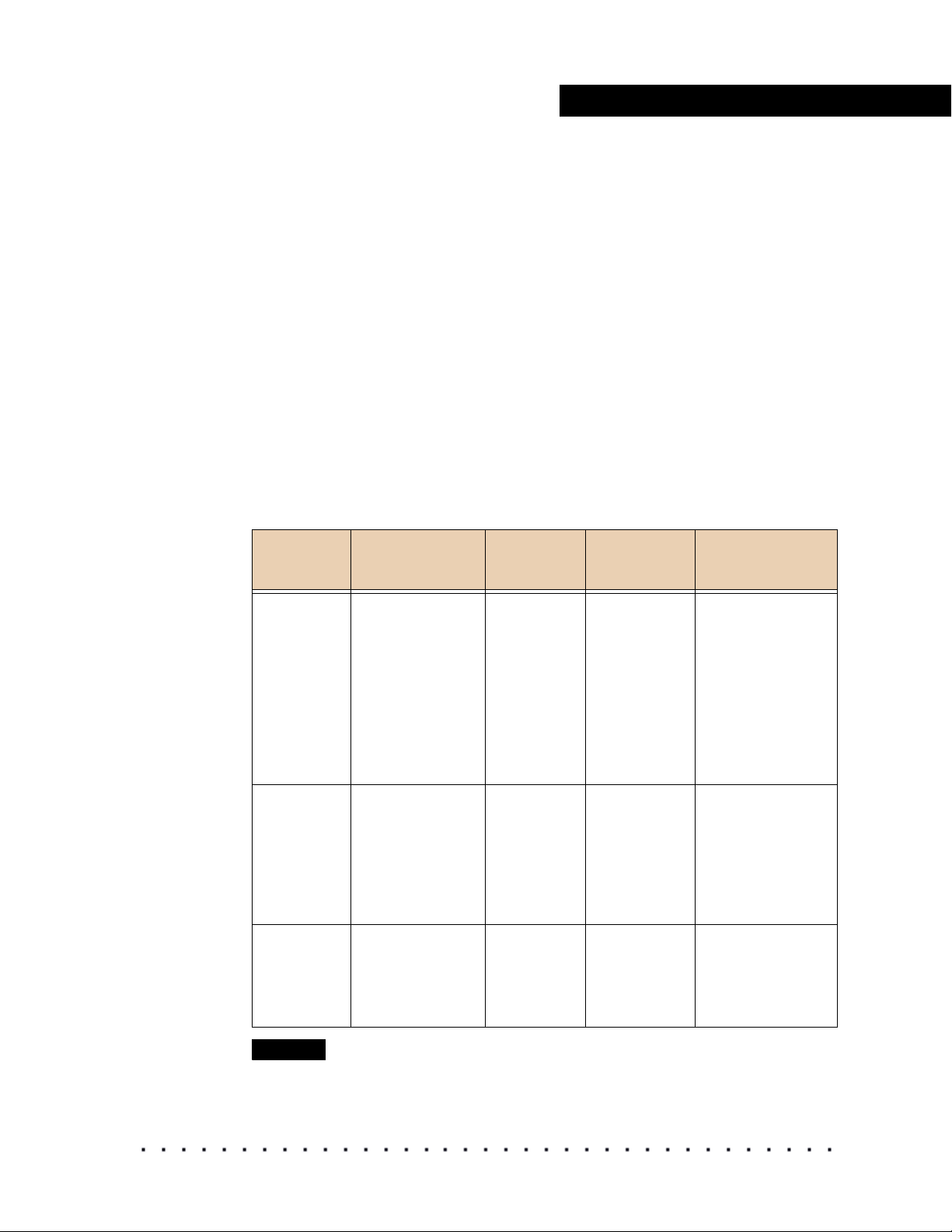
Types of Licenses
Print Film Edition
Time Limit term duration Variable duration -
Software Key Required Yes Yes
Monitor Calibration Yes Yes
Monitor Characterization Yes Yes
HD/SD Display
Characterization
Projector Characterization Yes Yes
Print Look Emulation Yes No
Print Look Verification Yes No
Calibration Verification Yes Yes
Video Look Emulation Yes Yes
Yes Yes
VISION2 HD
System Edition
dependant on loan
agreement
Export 3D LUT Yes Yes
Image Input Type .dpx, .cin, .tif (with
video content)
Operating Systems WINDOWS 2000/XP
MAC OS 10.2 or
higher
MAC OS X 10.4 Tiger
IRIX 6.5X
LINUX Red Hat 9
(ia32 only)
Red Hat Enterprise
LINUX 3.0 (ia32 only)
FEDORA Core 3
(ia32 only)
2 KODAK Display Manager System V4.0 User’s Guide
.tif (with video content)
WINDOWS 2000/XP
MAC OS 10.2 or
higher
MAC OS X 10.4 Tiger
IRIX 6.5X
LINUX Red Hat 9
(ia32 only)
Red Hat Enterprise
LINUX 3.0 (ia32 only)
FEDORA Core 3
(ia32 only)
Page 13

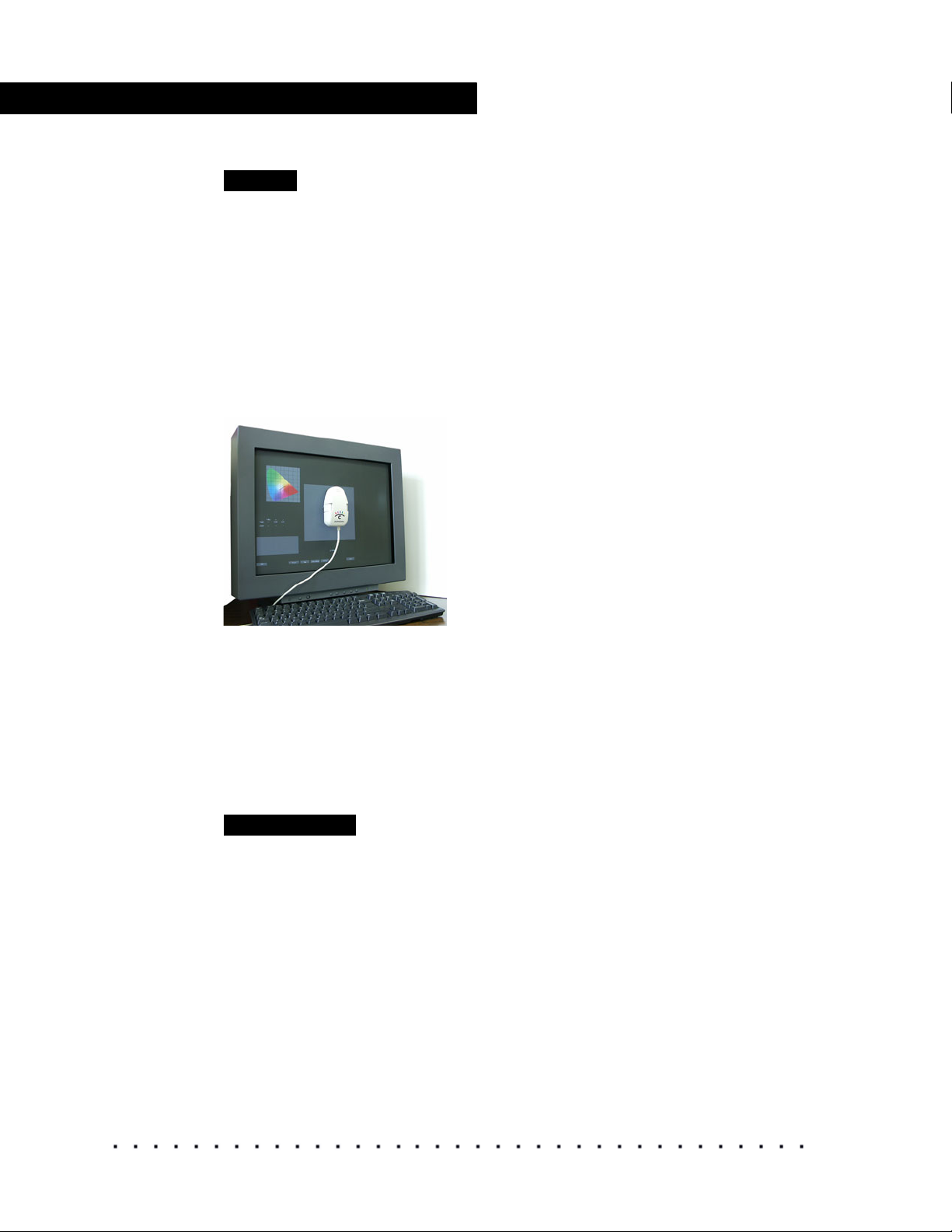
How it Works
To accurately generate a 3D LUT, you must work from a calibrated and
characterized display. A sensor, which you position on your display, measures
the luminance and chromaticities of a series of color patches. You can also
use the sensor to verify the calibration and characterization.
NOTE
To characterize a projector you must use a spectrophotometer or a colorimeter
suitable for measuring screen reflectance.
Calibration
The automatic calibration process gathers information from a sensor and
transfers it to the monitor via the enable cable (USB Cable ECC 1).
Adjustments are automatically made to the monitor contrast, brightness, and
individual RGB biases and gains via the enable cable, based on information
gathered by the sensor.
The first time that you initiate automatic calibration, the system prompts you to
perform a monitor evaluation to determine if your monitor is capable of being
automatically calibrated.
Introduction
When calibrating an HD/SD device, you must manually calibrate the device
using standard SMPTE procedures. A colorbars target is supplied with the
Display Manager System.
Manually calibrate your display to SMPTE standards if:
• You are using an IRIX system
• You have an HD/SD device
• The enable cable does not recognize your monitor
• You were unable to successfully calibrate your monitor using automatic
calibration
Characterization
After you have calibrated your display, you must characterize it to determine
the gamma response and to track the primaries. The result is a .chr file, which
the system uses to create a 3D LUT.
HD/SD displays and digital projectors must be characterized using the Manual
Characterization Assistant. When characterizing these types of displays, you
can project display patches provided on the Display Manager System CD
through a supported imaging application (or you can display patches from one
of the KODAK color patch set video tapes available from Kodak).
KODAK Display Manager System V4.0 User’s Guide 3
Page 14

Introduction
Viewing and Customizing a Look
Verification
From the Display Manager System Viewer, you can view images and apply a
transform, which can be either a .chr file or a 3D LUT. With a properly
calibrated and characterized monitor, images will closely match a projected
print film image or broadcast image.
Perform a verification to measure the quality of the monitor setup and to
measure the closeness of the print film match in CIElab colorspace.
NOTE
Verification is not available for HD/SD displays and digital projectors.
4 KODAK Display Manager System V4.0 User’s Guide
Page 15
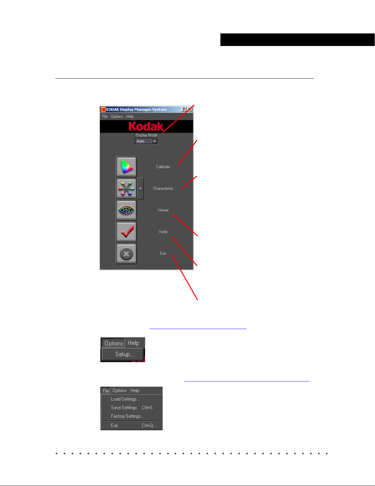
Main Window
The main window contains a selection box for the Display Mode and an icon
for each step in the process.
Introduction
Display Mode: Select Auto if you will be
using the enable cable to calibrate. If not,
it is important that you select Manual.
Calibrate: Opens the Calibration window
where you attach a sensor to measure the
luminance and chromaticity of a series of
color patches.
Characterize: Opens the Characterization
window where you attach a sensor to
measure the luminance and chromaticity of
a series of color patches. Choose Manual
Characterization Assistant to
characterize alternate display devices, such
as HD/SD displays and digital projectors.
Viewer: Opens the Viewer where you load
and view images, customize looks, and
build and export 3D LUTs.
Verify: Opens the Verification window
where you attach a sensor and verify the
quality of the monitor setup and the print
simulation.
Exit: Closes the application.
From the Options menu, select Setup to set the parameters and configure
the system. See “Setting the Options” on page 22.
From the File menu, load your settings, save your settings or reset to the
factory default settings. See “
Saving and Loading Settings” on page 28.
KODAK Display Manager System V4.0 User’s Guide 5
Page 16

Introduction
Supported Hardware
The following hardware is recommended for use with the Display Manager
System.
Generic Monitor Support
The Display Manager System supports many different monitors but not all
monitors can be automatically calibrated by the system. Most high-quality
professional grade monitors can be calibrated.
The first time that you initiate an automatic calibration, you are prompted to
attach a sensor to the monitor so that the system can assess if the monitor
can be automatically calibrated.
NOTE
Before running this evaluation, set your monitor to Expert mode and turn off the
Super Bright mode if applicable.
You are then notified if the monitor can be automatically calibrated. If it cannot,
you can manually adjust your monitor using SMPTE standard procedures and
the supplied colorbars chart. For more information, see “
on page 34.
Manual Calibration”
This evaluation runs whenever you attach a monitor that was not previously
tested with the system and then initiate automatic calibration.
Supported Displays
In addition to displays that can be automatically calibrated, you can use the
Display Manager System with LCD monitors, HD/SD displays, and digital
projectors. We recommend cinema grade digital projectors.
Enable Cable (USB Cable ECC 1)
An enable cable is required to transfer data from your monitor to your
computer. This cable can be obtained through Kodak. Contact your service
representative. See “
Supported Spectrophotometers” on page 8.
6 KODAK Display Manager System V4.0 User’s Guide
Page 17
Supported Sensors
The following sensors are supported by the Display Manager System:
• X-RITE Monitor Optimizer DTP94+EK (also known as MonacoOPTIX) USB connection for LCD or CRT monitors
• X-RITE Monitor Optimizer DTP92+EK - serial connection for CRT monitors
• SEQUEL Chroma 4/C USB - USB connection for CRT monitors,
• SEQUEL Chroma 4/C USB with USB cable - for CRT monitors,
• SEQUEL Chroma 4/C Serial - Serial connection for CRT monitors,
• SEQUEL Chroma 4/L - USB connection for LCD monitors,
• USB Cable for VESA compliant CRT monitors
• PHOTO RESEARCH PR-650 - Serial connection for digital projection
• MINOLTA CS-100A - Serial connection for digital projection
To purchase the X-RITE, PHOTO RESEARCH or MINOLTA sensors, contact
the manufacturer.
Refer to the following table when deciding the sensor to use with your system.
Introduction
CRT
Monitors
and HD/SD
displays
LCD
Monitors
Digital
Projectors
WINDOWS
OS
X-RITE
DTP94+EK
X-RITE
DTP92+EK
SEQUEL
Chroma 4/C
USB
SEQUEL
Chroma 4/C
Serial
X-RITE
DTP94+EK
SEQUEL
Chroma 4/L
USB
PHOTO
RESEARCH
PR-650
MINOLTA
CS-100A
MAC OS IRIX OS LINUX OS
X-RITE
DTP94+EK
SEQUEL
Chroma 4/
C USB
X-RITE
DTP94+EK
SEQUEL
Chroma 4/L
USB
SEQUEL
Chroma 4/C
Serial
SEQUEL
Chroma 4/C
USB
X-RITE
DTP92+EK
X-RITE
DTP92+EK
PHOTO
RESEARCH
PR-650
MINOLTA
CS-100A
SEQUEL Chroma
4/C USB
SEQUEL Chroma
4/C Serial
X-RITE
DTP92+EK
X-RITE
DTP94+EK
SEQUEL Chroma
4/L
USB
X-RITE
DTP92+EK
X-RITE
DTP94+EK
PHOTO
RESEARCH PR650
MINOLTA
CS-100A
NOTE
USB sensors are recommended for any system that is USB enabled.
KODAK Display Manager System V4.0 User’s Guide 7
Page 18

Introduction
Supported Spectrophotometers
When characterizing a digital projector, you must take readings from the
projector output. The following sensors are recommended:
• MINOLTA CS-100A
• PHOTO RESEARCH PR-650
Getting Help
Accessing the Help System
To access the Help system from within the application, click Help > Contents.
What’s This
(WINDOWS only) Press Shift + F1 and a pop-up window opens that
describes the current window.
OR
Click the question mark in the window title bar and then click the item for which
you want more information. A pop-up window opens.
To open What’s This topics in the Viewer, right-click (WINDOWS, IRIX,
LINUX) or Ctrl + click (MACINTOSH) an item in the toolbar.
Troubleshooting
Consult the Troubleshooting chapter for issues that you might encounter. See
Troubleshooting” on page 71.
“
Email Help
Email questions to tac@ei.kodak.com.
Phone Support
Go to the website www.kodak.com/go/dm to locate the support number for
your region.
8 KODAK Display Manager System V4.0 User’s Guide
Page 19

INSTALLING AND SETTING UP
Follow these four main steps to install and set up your system:
• Step 1: Install the KODAK Display Manager System Software
• Step 2: Connect the Hardware
• Step 3: Obtain your License
• Step 4: Open the Software
Step 1 Install the Software
IMPORTANT
Before installing the Display Manager System, make sure to uninstall any other
monitor calibration software that you might have on your system.
Installing and Setting Up Your System
Y
OUR SYSTEM
WINDOWS and MACINTOSH Operating System Installation
IMPORTANT
You must be logged in as administrator (WINDOWS or MACINTOSH Operating
Systems) to install the Display Manager System.
To install on a WINDOWS or MACINTOSH Operating System:
1. Insert the installation CD.
2. (WINDOWS Operating System) Follow the on-screen prompts.
Or
(MACINTOSH Operating System) Double-click kdminstaller.pkg and
follow the onscreen prompts.
3. Connect the hardware to your computer. See “Step 2: Connect the
Hardware” on page 11.
KODAK Display Manager System V4.0 User’s Guide 9
Page 20
Installing and Setting Up Your System
IRIX Installation
IMPORTANT
You must be logged in as root (IRIX Operating System) to install the Display
Manager System.
To install the Display Manager System on an IRIX computer, you should be
familiar with the IRIX inst or swmgr command.
The required files can be found on the installation CD in the dist directory.
Make sure that you have the following files:
•kdm
• kdm.idb
•kdm.sw
The IRIX computer must be running IRIX 6.5x with the corresponding version
of NFS.
To install on an IRIX system:
1. Insert the installation CD into the CD-ROM drive.
2. Mount the CD-ROM.
3. Launch inst or swmgr.
4. Select the kdm package from the mounted CD-ROM drive.
5. Complete the installation by following the on-screen prompts.
6. Connect the hardware to your computer. See “Step 2: Connect the
Hardware” on page 11.
LINUX Installation
IMPORTANT
You must be logged in as root (LINUX Operating System) to install the Display
Manager System.
To install on a LINUX system:
1. Insert the installation CD into the CD-ROM drive.
2. Mount the CD.
3. Change directory to the mounted CDROM.
4. Type rpm -Uvh KODAK_DMS-4.0.0.i386.rpm to begin the installation
process.
5. Connect the hardware to your computer. See “Step 2: Connect the
Hardware” on page 11.
NOTE
Configure your panel (taskbar) to allow other windows to appear above. Or set
your panel to autohide.
10 KODAK Display Manager System V4.0 User’s Guide
Page 21
Installing and Setting Up Your System
Step 2: Connect the Hardware
Before connecting the hardware, install the software.
The Display Manager System hardware consists of an enable cable and
sensor. Purchase the sensor that is appropriate for your system configuration.
“Supported Sensors” on page 7 to learn about the sensors supported by
See
the Display Manager System.
If you do not have enough available USB ports, use a USB hub when
connecting the enable cable and sensor.
If you must run the cables long distances, you may need to purchase a Port
Authority device and additional cables.
(WINDOWS) After you connect the hardware, click Next when the Found New
Hardware Wizard opens. Follow the on-screen prompts. If you are prompted to
locate the drivers:
• SEQUEL drivers are found in C:\Progam Files\Kodak\KODAK Display
Manager System\SequelDrivers.
• X-RITE drivers are found in C:\Progam Files\Kodak\KODAK Display
Manager System\XRiteDrivers.
NOTE
For digital projectors, MINOLTA CS-100A or PHOTO RESEARCH PR-650
sensors are recommended.
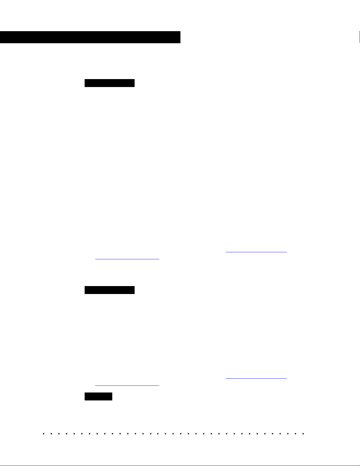
Enable Cable (USB Cable ECC 1)
The enable cable allows the computer to talk to the monitor. It connects to the
monitor port, a USB port, and then to the monitor cable.
You may need a DVI to HD15 pin adapter depending on your configuration.
Connect to the
monitor cable
Connect to a USB
port
NOTE
(WINDOWS 2000 only) If you unplug the enable cable or sensor and then plug
it back in, the system will not recognize it until you restart your computer.
Connect to the
computer monitor port
KODAK Display Manager System V4.0 User’s Guide 11
Page 22
Installing and Setting Up Your System
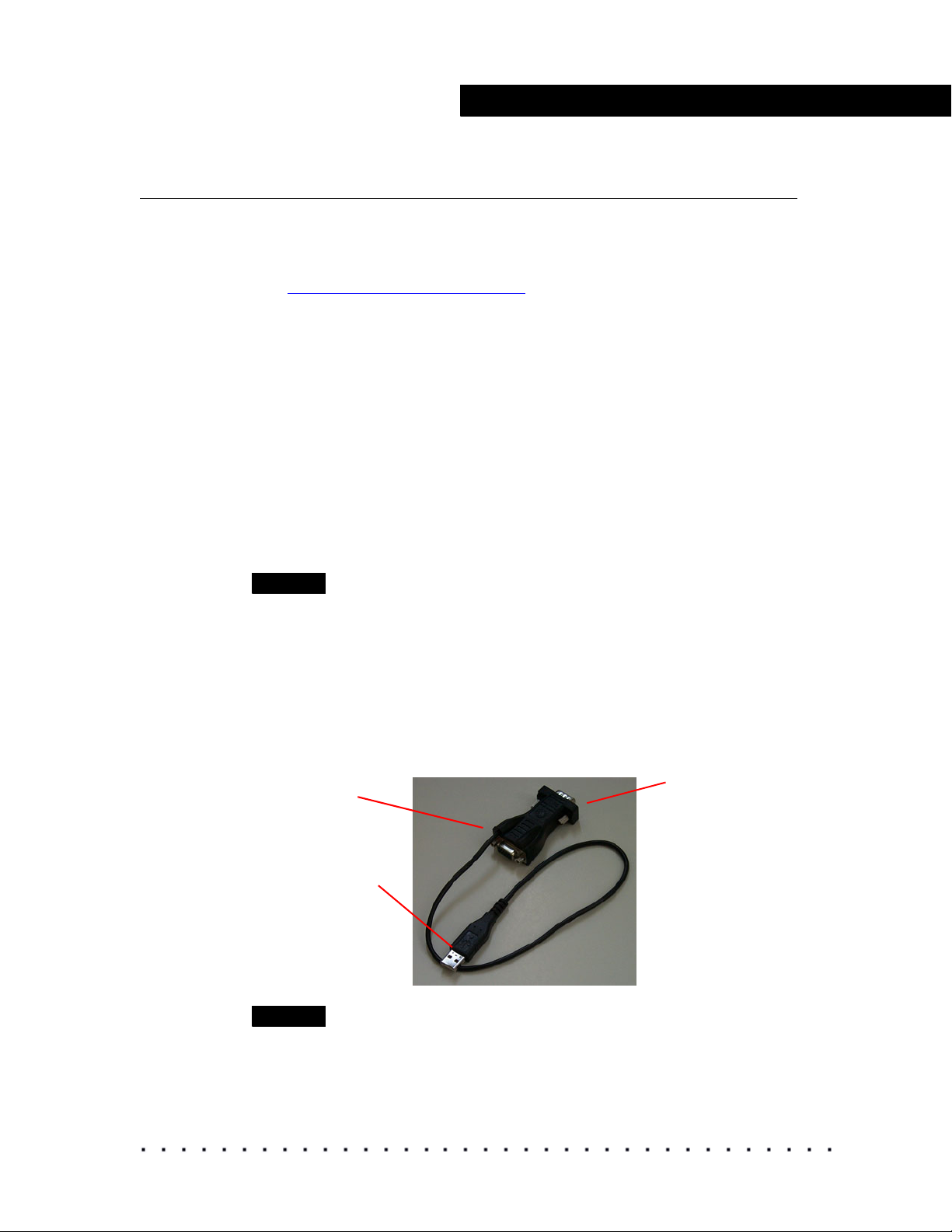
To connect the enable cable:
1. Disconnect the original monitor cable from the computer.
2. Attach the enable cable to the monitor port on the computer.
3. Connect the monitor cable to the enable cable.
4. Attach the USB connector of the enable cable to a USB port.
USB connection
Enable cable connection
Monitor cable connection
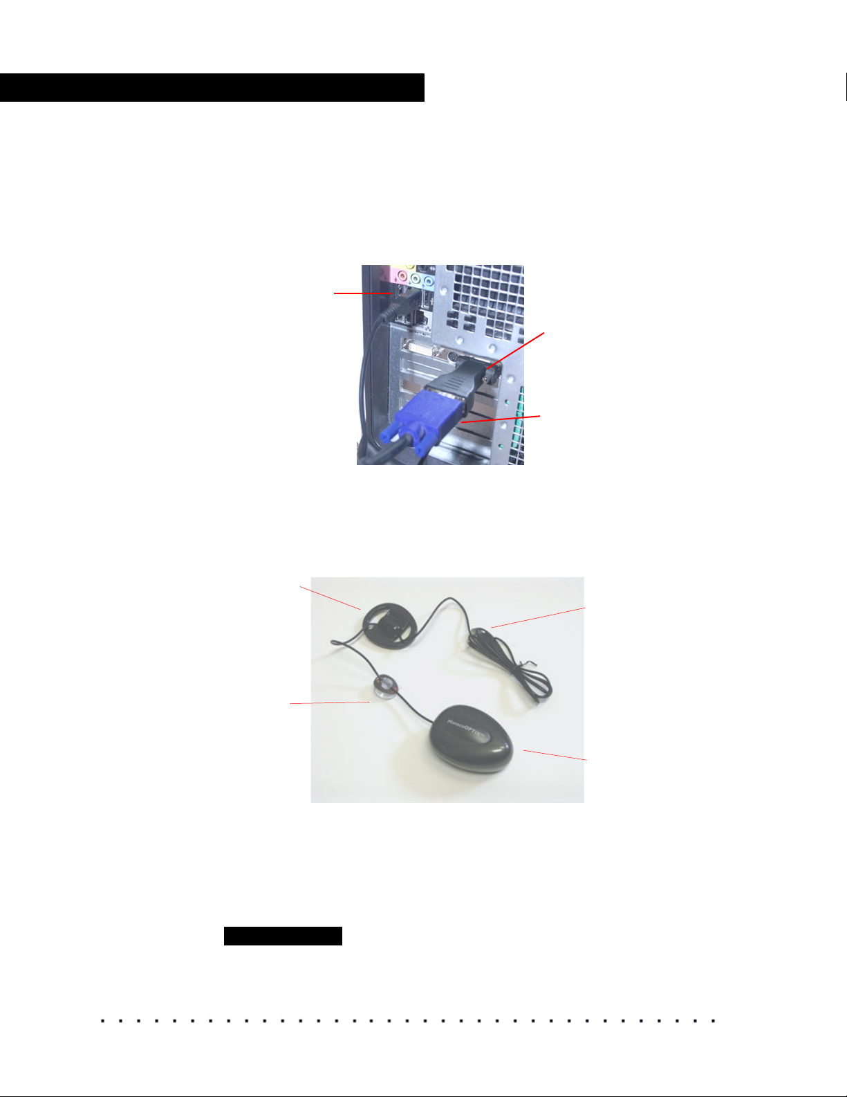
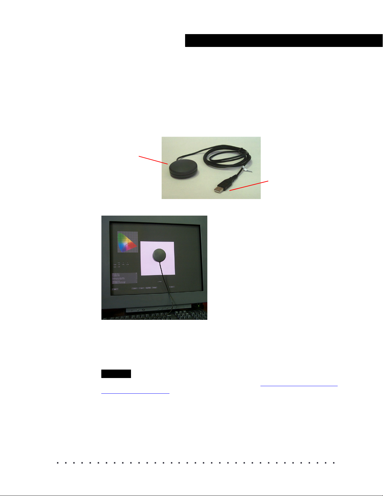
X-RITE Sensors
X-RITE Monitor Optimizer DTP94+EK (MonacoOPTIX)
Use this USB sensor on CRT or LCD monitors.
Counterweight Attach to the
sensor cable to
counter balance
the sensor.
Suction cup Attach to the
cable and then
fasten the suction
cup to the screen.
Supports the
instrument's
weight when
using CRT
monitors.
To position the sensor during calibration:
1. Attach the counterweight to the cable.
2. If using a CRT monitor, attach the suction cup to the sensor cable and
then fasten the suction cup to the screen.
USB connection Connect to a USB
port on your
computer.
Sensor - Hang in
front of the monitor
to measure
patches.
IMPORTANT
Never use the suction cup on an LCD monitor.
12 KODAK Display Manager System V4.0 User’s Guide
Page 23
Installing and Setting Up Your System
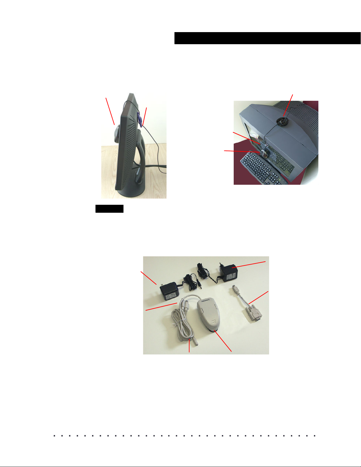
3. Position the sensor on the screen. Position the counterweight so that it
counterbalances the sensor.
LCD monitor CRT monitor
Sensor
Counterweight
Suction cup
Sensor
Counterweight
NOTE
If you are warned that the X-Rite DTP94 software has not passed Windows
Logo testing, click Continue Anyway.
X-RITE Monitor Optimizer DTP92+EK
Use this serial sensor on CRT monitors.
120V power supply
Adapter connections
Power supply
connection
Sensor
230V power supply
WINDOWS adapter
KODAK Display Manager System V4.0 User’s Guide 13
Page 24
Installing and Setting Up Your System
NOTE
On IRIX, do not use serial port 1.
To connect the sensor:
1. Connect the WINDOWS adapter to the sensor cable.
2. Plug the WINDOWS connector into a serial port.
3. Plug the AC adapter connector into the sensor cable.
4. Plug the AC adapter into a power outlet.
During calibration, attach the sensor as shown here, making sure that the
round portion of the sensor is at the top.
Firmly push on the sides of the sensor so that the spring-loaded suction cup
slides forward onto the screen. When the suction cup is firmly in place, release
the sensor.
You may need to moisten the suction cup by wiping it with a tissue lightly
dampened with water, or to fog the suction cup by breathing on it.
You may need to clean the monitor and suction cup, if the sensor does not
firmly attach. Clean the suction cup with a clean dry cloth.
IMPORTANT
Do not apply a cleanser to the suction cup.
To clean the monitor, use a soft, lint-free paper or cloth lightly dampened with
a mild glass cleaner.
14 KODAK Display Manager System V4.0 User’s Guide
Page 25
SEQUEL Sensors
A
s
Three Sequel sensors are recommended for use with the Display Manager
System.
SEQUEL Chroma 4/C USB Sensor for CRT Monitors
This sensor connects to a USB port and attaches to a CRT monitor with
suction cups.
ttach to the
monitor with
uction cups
During calibration, attach the sensor as shown here.
Installing and Setting Up Your System
Connect to the
computer USB port
Press the sensor firmly to the screen being careful not to press too hard.
Center it within the patch. Make sure that all suction cups are pressed against
the monitor. If any of the suction cups come loose, the results may be
unreliable and the process should be repeated. If the sensor falls off the
monitor, reattach it and restart the process.
NOTE
You may need to clean the sensor and the screen. See “Sensor Does Not Adhere
to Screen” on page 75.
KODAK Display Manager System V4.0 User’s Guide 15
Page 26
Installing and Setting Up Your System
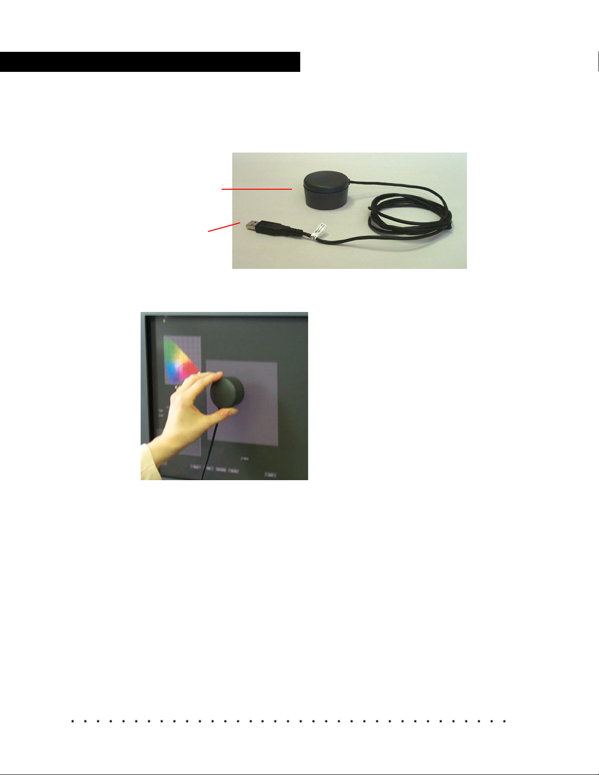
SEQUEL Chroma 4/L USB Sensor
This sensor connects to a USB port. Tip the LCD screen back as far as
possible and hold the sensor against the screen while it is taking readings.
Hold the sensor
against the screen
Connect to the
computer USB port
During calibration, hold the sensor as shown here.
Hold the sensor firmly to the screen being careful not to press too hard. Center
it within the color patch. Continue to hold in place while readings are taken.
16 KODAK Display Manager System V4.0 User’s Guide
Page 27
Installing and Setting Up Your System
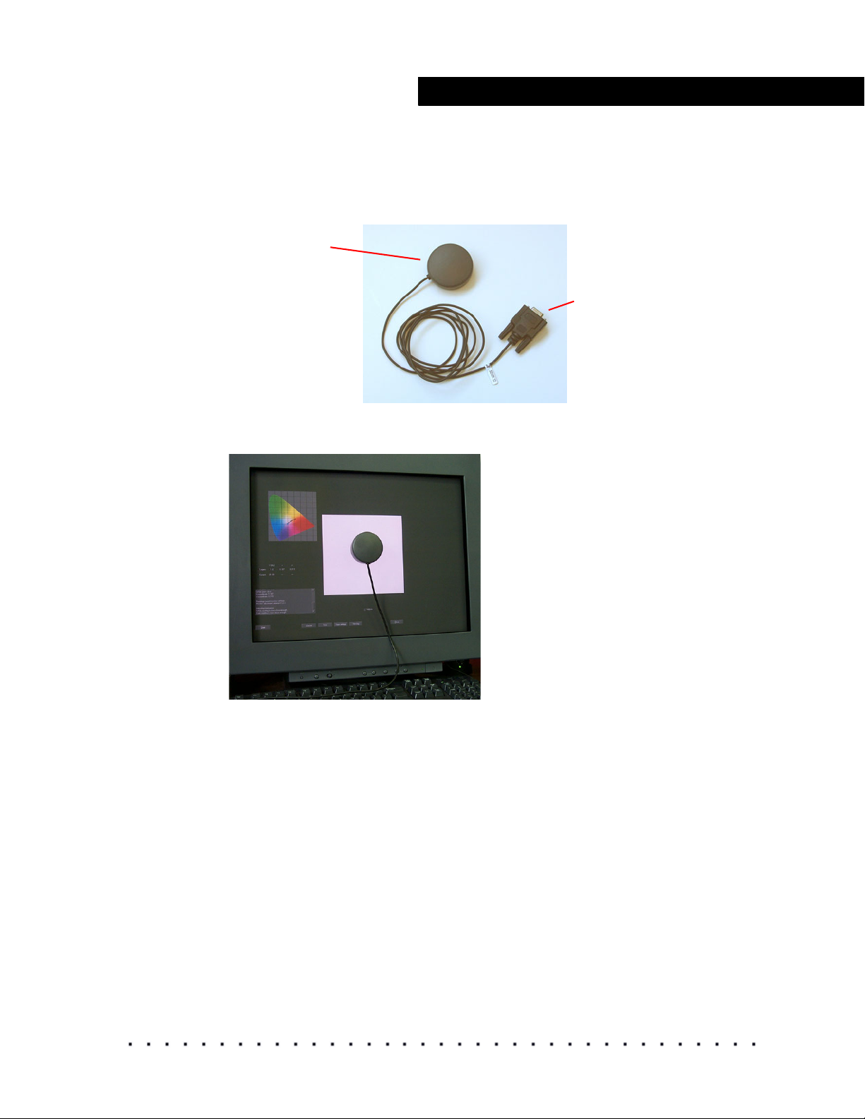
SEQUEL Chroma 4/C Serial Sensor for CRT Monitors
The sensor connects to a USB port and attaches to a CRT monitor with
suction cups.
Attach to monitor
with suction cups
Connect to serial port on your
computer
NOTE: On IRIX, do not use
serial port 1.
During calibration, attach the sensor as shown here.
Press the sensor firmly to the screen being careful not to press too hard.
Center it within the color patch. Make sure that all suction cups are pressed
against the monitor. If any of the suction cups come loose, the results may be
unreliable and the process should be repeated. If the sensor falls off the
monitor, reattach it and restart the process.
Sensors Recommended for Digital Projection
• MINOLTA CS-100A
• PHOTO RESEARCH PR-650
KODAK Display Manager System V4.0 User’s Guide 17
Page 28

Installing and Setting Up Your System
PHOTO RESEARCH PR-650
1. Attach the PHOTO RESEARCH IFC-600 RS-232 cable between the PR650 and the computer serial port.
2. Go to Options > Setup.
3. Click the Sensor tab.
4. Click Type and select PhotoResearch PR-650.
5. Click Connection and select the com port that the meter is connected to.
NOTE
Do not turn on the device until instructed by KODAK Display Manager Software.
MINOLTA CS-100A
1. Attach the MINOLTA LS-A12 two way interface cable between the
MINOLTA CS-100A and the computer serial port.
2. When turning the device on, press and hold the F button until a C appears
in the device external display.
3. Go to Options > Setup.
4. Click the Sensor tab.
5. Click Type and select MINOLTA CS-100A.
6. Click Connection and select the com port that the meter is connected to.
18 KODAK Display Manager System V4.0 User’s Guide
Page 29
Installing and Setting Up Your System
Step 3: Obtain Your License
If you would like a free trial, go to the website www.kodak.com/go/dm and click
Trial LIcense Key. Follow the on-screen prompts, then proceed to Step 5
(below).
To purchase a license:
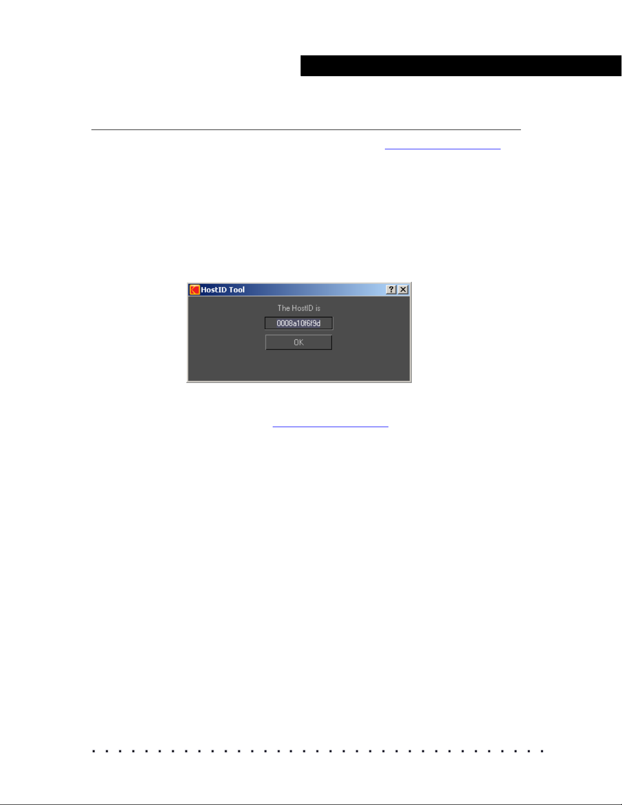
1. (WINDOWS Operating System) Click Start > Programs > KODAK
Display Manager System > KODAK HostID Tool.
(LINUX, IRIX, MACINTOSH Operating Systems) In the Display Manager
System main folder locate the KODAK HostID Tool and run the file.
The following window opens.
2. Record all HostIDs and click OK.
3. Go to the website www.kodak.com/go/dm and locate the phone number
for the customer service representative in your region.
4. Provide your customer service representative with the HostID.
License information will be emailed to you.
5. When you receive your license information, copy and paste the
information into an editor such as WordPad and save it as kdm.lic. Place
the file as follows:
WINDOWS Operating System: C:\Program Files\KODAK\KODAK
Display Manager System\Licenses
MACINTOSH Operating System: /Applications/KODAK Display
Manager System/Licenses
IRIX and LINUX Operating Systems: /usr/local/KDM/Licenses
KODAK Display Manager System V4.0 User’s Guide 19
Page 30

Installing and Setting Up Your System
Step 4: Open the Display Manager System
On a WINDOWS or MACINTOSH system, double-click the desktop icon
to open the Display Manager System.
On an IRIX or LINUX system:
1. Open a shell and change to the directory /usr/local/KDM.
2. From the command line, type ./kdm.sh.
Renewing Your License
You will be prompted when your license expires. Contact your customer
service representative to purchase a new license.
20 KODAK Display Manager System V4.0 User’s Guide
Page 31

BEFORE CALIBRATING
Before you begin to calibrate, make sure that you:
• Prepare the monitor and viewing environment
• Setup the system options for calibration, sensors, tolerances, display,
timing, and directories
• Load specific settings, if previously saved
NOTE
You do not need to setup the system options each time you calibrate. When the
system opens, it automatically loads the settings that you save in the kdm.ini
file. Or you can create and load a customized .ini file. See “
Settings” on page 28.
Preparing the Viewing Environment and Monitor
• Let the CRT monitor warm up for at least one hour. LCD monitors take 10
to 15 minutes to warm up.
• Set your power save mode to Never.
• Disable your screen saver.
• Set your screen resolution to at least 1280 x 1024.
• Dim the room lights or cover the screen with a dark cloth. There should be
no light shining on the screen or on objects that might reflect on the
screen.
• Set the monitor in Expert mode, if available.
a) From the panel at the front of the monitor, select COLOR.
Saving and Loading
b) Use the left and right arrow buttons on the panel to highlight the
Expert tab, where you see the bias and gain settings.
NOTE
For some monitors, the Expert mode is already selected as the default.
• If you have a newer SONY monitor that has a Picture effect button on the
panel at the front of the monitor, press this repeatedly until the message
DYNAMIC appears on screen.
• Set the monitor color quality to the highest possible value (at least 16 bits).
• If your display supports Super Bright mode, turn off the Super Bright mode
by repeatedly pressing the SB button on the front of the monitor until the
screen reads “Super Bright Mode Off”.
KODAK Display Manager System V4.0 User’s Guide 21
Page 32

Before Calibrating
Setting the Options
Go to Options > Setup to open the Setup window. From this window you can:
• Set the calibration parameters
• Identify the sensor you are using
• Set tolerances
• Select which display to calibrate on a dual-head system
• Control the calibration timing
• Set the paths for saving .chr files and LUTs
After you have made all of your selections on the various tabs, click Save
Settings to save all the settings in a .ini file. By default, settings are saved to
the kdm.ini file. When the system opens, it automatically loads the settings
that you save in the kdm.ini file. Save your settings with a different file name
to create a customized .ini file. See
page 28.
22 KODAK Display Manager System V4.0 User’s Guide
“Saving and Loading Settings” on
Page 33

Print Film Calibration Setup
The Print Film Calibration tab on the Setup window contains information that
is required to obtain an accurate print film match.
Before Calibrating
Projector Aim:
Projector aim values specify the intended film projector open gate settings.
Enter the values for the film projector you are emulating. If you have not
characterized a specific projector, use the default values.
• White Luminance (Y) - Open gate luminance can be measured by a
colorimeter or spectrophotometer. Enter the value in ft-lamberts.
• White Chromaticity (xy) - Open gate chromaticity can be measured by a
colorimeter or spectrophotometer. Enter values in CIE xy.
• Projector SPD (Spectral Power Distribution) - Click this button to open a
browse window where you can load a file that was created when
measuring your projector with a spectroradiometer. This file should be a
single column of values corresponding to measurements from
to 970 nm in 10 nm increments. Comment lines may be included in
340
the file preceded by a # sign.
•Select Projector Aim Luminance Adjust to bring the brightness of the
display down to the projector aim when simulating the print look. Deselect
this option to keep the brightness at the Display Aim.
KODAK Display Manager System V4.0 User’s Guide 23
Page 34

Before Calibrating
Display Aim:
Enter the desired White Luminance for the monitor in ft-lamberts. Setting
your monitor to the projector aim (typically 16 ft-lamberts) would make it too
dark for other work. The display aim gives you the opportunity to set a higher
display aim luminance.
Display - Automatic Calibration:
NOTE
The automatic calibration process tries to match all the values that you enter in
this section.
• From the Target drop-down list, select your monitor preset target that you
want to over-write during calibration.
• Set the Dark (code value). We recommend using the default settings.
• To override the projector Luminance and Chromaticity aim, check
Override Projector Aim for Dark Patch. The value fields become active
and you can enter new values for Dark Luminance (Y) and Dark
Chromaticity (x,y). We recommend using the default settings.
NOTE
The Use Print Film Calibration Settings checkbox is available in the Display
Manager System Print Film Edition. Select this checkbox to use the Print Film
target values in calibration.
24 KODAK Display Manager System V4.0 User’s Guide
Page 35

Video Calibration Setup
The Video Calibration tab on the Setup window contains information that is
required to obtain an accurate video match.
Aim Settings
Enter the values for the video space you want to calibrate to (CCIR 709,
SMPTE RP145, or User Defined).
Before Calibrating
The default values represent a typical NTSC HD display. These values can be
altered for a user defined video space.
• White Point Chromaticity (xy) - Desired white chromaticity. Enter values
in CIE xy.
White Patch
• White Luminance (Y) - Desired white (max neutral code value) luminance
can be measured by a colorimeter or spectrophotometer. Enter the value
in ft-lamberts.
NOTE
Recommended practices for HD/SD video monitors place video legal whites
at a luminance of approximately 30 ftL. Translating video 100% legal white
(code value of 940) to a maximum monitor drive code value of 1023 (10-bit)
yields an absolute monitor white luminance recommendation of
approximately 34 ftL This high luminance setting may degrade the useful
lifetime of some monitors
Dark Patch
• To override the video Dark (code value) settings, check Override
Calculated Aims for Dark Patch. The value fields become active and you
can enter new values for Dark Luminance (Y). We recommend using the
default settings.
KODAK Display Manager System V4.0 User’s Guide 25
Page 36

Before Calibrating
Use Video Calibration Settings
• Select this checkbox to determine which target values to use for
calibration.
NOTE
If using the KODAK VISION2 HD System, use the default values when working
with typical NTSC HD display.
Sensor Setup
From the Sensor tab on the Setup window, use the drop-down menus to
select the type of sensor and the type of connection
IMPORTANT
If you do not select the correct sensor and connection, the sensor will fail to
initialize.
.
Tolerances Setup
From the Tolerances tab on the Setup window, you can set the plus or minus
calibration tolerances that you want to allow for your aim values. We
recommend using the default settings.
Display Setup
If your system is configured for dual-head support, you must select the display
that you want to view images on.
From the Display tab on the Setup window, use the Display to Operate On
drop-down menu to select the display where you want to view the images.
This display will be calibrated and characterized
.
26 KODAK Display Manager System V4.0 User’s Guide
Page 37

Timing Setup
Adjusting the time between the appearance of color sets and individual color
patches, affects the total time to calibrate and characterize your display.
IMPORTANT
You may encounter calibration and characterization errors if the timing is set too
fast. We recommend leaving the values set at the default. Never set the timing
slower than the defaults.
From the Times tab on the Setup window, use the arrows to set the values.
Before Calibrating
Directories Setup
From the Directories tab on the Setup window, click the CHR Directory and
LUT Directory buttons to select the directories where you want to save those
files.
KODAK Display Manager System V4.0 User’s Guide 27
Page 38

Before Calibrating
Saving and Loading Settings
If you are working on several projects at one time, you may find it convenient
to save all of the settings for each project in a customized .ini file. Load the
appropriate file to quickly change all your settings when you change projects.
By default, settings are saved to the kdm.ini file. This is the file that is used
each time the system opens. There are two different locations where you can
save settings to an .ini file—the Setup window and the Viewer.
To create a customized .ini file:
1. Go to Options > Setup. Enter the appropriate values and click Save
Settings. Name the file appropriately.
2. Open the Viewer and make the appropriate selections. Click Save
Settings. Save the file with the same name used in step 1.
To load a customized .ini file:
1. Go to File > Load Settings.
2. Browse for and double-click the .ini file that you want to use.
To save all settings at once:
Go to File > Save Settings.
28 KODAK Display Manager System V4.0 User’s Guide
Page 39

Calibration
CALIBRATION
From the Display Mode drop-down menu on the main window, select either
Auto or Manual calibration.
Automatic calibration uses the enable cable to transfer data from the computer
to a monitor. Adjustments based on this data are automatically made to your
monitor. See
The Manual Calibration Assistant is used to adjust your monitor to SMPTE
standards if:
• You are using an IRIX system
• You are displaying your images on an HD/SD display or digital projector
• The enable cable does not recognize your monitor
• You were unable to successfully calibrate your monitor using automatic
calibration
See “Manual Calibration” on page 34.
“Automatic Calibration” on page 29.
Automatic Calibration
Use this calibration method if you are using an enable cable to transfer data
from your monitor to your computer. The system performs an evaluation to
determine if your monitor can be automatically calibrated.
IMPORTANT
If your system is far from the calibration aims, you may need to repeat the
calibration process more than once to reach aim. See “
page 72.
Calibration Failure” on
KODAK Display Manager System V4.0 User’s Guide 29
Page 40

Calibration
The Calibration Procedure
To automatically calibrate a monitor:
1. Click Auto from the drop-down Display Mode menu if it isn’t already
selected.
NOTE
Auto mode is only available if you have connected the enable cable to your
computer.
2. Click the Calibrate icon.
If this is the first time that you have calibrated your current monitor, follow
the on-screen prompts to run a monitor evaluation. See “
Evaluation” on page 33.
Monitor
Either the Calibration window opens or you are prompted to perform a
Dark Gain Correction to reset the sensor.
If you are prompted to perform a Dark Gain Correction:
a) Place the sensor on a dark surface and make sure that no light can
reach it. Do not attach the sensor to the monitor for this correction.
b) Click OK.
IMPORTANT
If the Dark Gain Correction fails, see “Dark Gain Correction Failure” on
page 74.
30 KODAK Display Manager System V4.0 User’s Guide
Page 41

Calibration
The Calibration window opens when the dark correction is complete.
3. Position the sensor in the center of the patch.
4. Select Detailed if you want a detailed log to be written. (Recommended)
5. Cover the monitor and sensor with a dark cloth if you are not able to turn
off the room lights.
6. Click Start.
The sensor measures a series of patches. A log is written, target values
are displayed and points are plotted on a chromaticity diagram.
KODAK Display Manager System V4.0 User’s Guide 31
Page 42

Calibration
The process may take several minutes. You can click Pause if necessary.
NOTE
During the final stage of the calibration process, the gamut and log
information are hidden.
If automatic calibration is successful, automatic characterization begins
immediately after calibration is complete.
If automatic calibration was not successful, you may need to calibrate one or
more times. See
32 KODAK Display Manager System V4.0 User’s Guide
“Calibration Failure” on page 72.
Page 43

Monitor Evaluation
The first time that you initiate an automatic calibration, the system performs an
evaluation of your monitor to determine if it can be automatically calibrated. If
you change monitors, the system runs the evaluation again when you initiate
automatic calibration.
To evaluate your monitor:
1. With an enable cable and sensor connected to your system and the Auto
mode enabled, click Calibrate.
The following window opens.
2. Click Yes.
Calibration
IMPORTANT
You must select Yes and perform this evaluation in order to automatically
calibrate your monitor.
The following window opens.
3. Attach the sensor and click OK.
The system reads a series of patches and displays the results.
If your monitor can be automatically calibrated, the following message
appears.
Click OK.
KODAK Display Manager System V4.0 User’s Guide 33
Page 44

Calibration
If your monitor cannot be calibrated, the following message appears. Click
Yes to retry.
You must switch to Manual display mode and manually calibrate your monitor
if it cannot be automatically calibrated. See
Manual Calibration
You can manually calibrate your display by adjusting the white and black
points from your monitor controls.
Use this method to manually calibrate your display if:
• You are using an IRIX system
• You are displaying your images on an HD/SD display
• The enable cable does not recognize your monitor
• You were unable to successfully calibrate your monitor automatically
• You have an LCD monitor
“Manual Calibration” on page 34.
Use the colorbars target provided with your Display Manager System to assist
you in making these adjustments.
If using a digital projector, set the projector to the manufacturer’s defaults.
To manually calibrate a monitor or HD/SD display:
1. Select Manual from the drop-down Display Mode menu, if it isn’t already
selected.
34 KODAK Display Manager System V4.0 User’s Guide
Page 45

Calibration
2. From your imaging product, display the colorbars target that came with the
Display Manager System. Adjust the display brightness and contrast until
the pluge target blends into the background.
The colorbars target file is found on the Display Manager System
installation CD. Go to Images/ColorBar.dpx.
3. Click the Calibrate icon.
The following window opens.
KODAK Display Manager System V4.0 User’s Guide 35
Page 46

Calibration
4. Place the sensor face down against a flat, opaque surface (not the screen)
for dark gain correction (zero reading). Click OK when ready.
This may take several seconds.
5. Click Measure Primaries.
6. Place the sensor over the red patch. Click OK to measure.
7. Repeat step 6 for the green and the blue patches.
8. Measure white luminance:
a) Place the sensor on the white patch.
b) Click Measure Once or Measure Continuous.
c) Examine the results and adjust your display, referring to the
instructions on the screen.
d) If you clicked Measure Once in step b, repeat steps b and c until a
pop-up informs you that white luminance is within tolerance.
NOTE
Leave the sensor attached.
9. Measure white chromaticity:
a) Repeat steps 8b - 8d until white chromaticity is within tolerance.
10. Measure dark chromaticity:
a) Repeat steps 8b - 8d until dark chromaticity is within tolerance.
36 KODAK Display Manager System V4.0 User’s Guide
Page 47

Calibration
11. Repeat steps 8, 9, and 10 to verify that all values are within tolerance.
NOTE
The plot indicates where you are versus aim. Use the magnify buttons
to zoom in and out on the plot.
12. Click Close.
13. Proceed to “Characterization” on page 39.
KODAK Display Manager System V4.0 User’s Guide 37
Page 48

Page 49

CHARACTERIZATION
Characterization determines the gamma response of the calibrated monitor
and tracks monitor primary colors. You should perform a characterization after
each calibration.
The system uses the .chr file written during characterization to create a
LUT that can be exported to any supported imaging products.
3D
From the Characterize drop-down menu on the main window, choose either
Automatic Characterization or Manual Characterization Assistant.
Use Automatic Characterization if you performed automatic calibration or for
devices such as LCD or CRT displays that were NOT auto calibrated.
Use the Manual Characterization Assistant, if you performed a manual
calibration for an HD/SD display or digital projector.
Automatic Characterization
NOTE
If you successfully completed an automatic calibration, characterization will
automatically run. In this case, proceed to “
page 47.
To automatically characterize your monitor:
1. From the Characterize drop-down menu, click Automatic
Characterization.
KODAK Display Manager System V4.0 User’s Guide 39
Viewing and Customizing Looks” on
Page 50

Characterization
Either the Characterization window opens or you are prompted to perform
a Dark Gain correction to reset the sensor.
If you are prompted to perform a Dark Gain Correction:
a) Place the sensor on a dark surface and make sure that no light can
b) Click OK.
If the Dark Gain Correction fails, see “Dark Gain Correction Failure” on
page 74.
reach it. Do not attach the sensor to the monitor for this correction.
IMPORTANT
The Automatic Characterization window opens when the correction is
complete.
40 KODAK Display Manager System V4.0 User’s Guide
Page 51

Characterization
2. If the sensor is not already positioned, place it on the center of the screen.
“Step 2: Connect the Hardware” on page 11.
See
3. Cover the monitor and sensor with a dark cloth if you are not able to turn
off the room lights.
4. Click Start.
The application reads a series of patches. This process may take several
minutes.
5. Click OK when you are notified that the characterization has finished.
You can now create and apply a 3D LUT to emulate the print look or video
look. See
“Viewing and Customizing Looks” on page 47.
If you want more information on the quality of the calibration and
characterization, see
“Verifying the Monitor Setup” on page 63
If characterization failed, see “Characterization Failure” on page 73.
KODAK Display Manager System V4.0 User’s Guide 41
Page 52

Characterization
Manual Characterization
Use the Manual Characterization Assistant to characterize a display, such as
a digital projector or HD/SD display. Patches for use in characterizing HD/SD
displays and digital projectors are available on the KODAK Display Manager
System CD in the Images/Patches folder. The patches can also be displayed
from one of the following KODAK Video Tapes:
• KODAK Display Manager Dual-Length Color Patch Set / D5-HD Tape
#D5C63M, 1080i/50
• KODAK Display Manager Dual-Length Color Patch Set / D5-HD Tape
#D5C63M, 1080i/59.94
• KODAK Display Manager Dual-Length Color Patch Set / Digital BETACAM
Tape #BCT-D64, NTSC
• KODAK Display Manager Dual-Length Color Patch Set / Digital BETACAM
Tape #BCT-D64, PAL
• KODAK Display Manager Dual-Length Color Patch Set / HDCAM Tape
#BCT-64HD, 1080i/50
• KODAK Display Manager Dual-Length Color Patch Set / HDCAM Tape
#BCT-64HD, 1080i/59.94
The tapes contain 15 sec. patches for use with SEQUEL and X-RITE sensors
and 40 sec. patches for use with the PHOTO RESEARCH PR-650 and
MINOLTA CS-100A sensors. A slate indicates the start of each patch set.
NOTES:
• If you use a KODAK video tape for manual characterization, the
measurements may be automatically entered into the Manual
Characterization Assistant (depending on the device you are using).
• When manually characterizing, you can create and save characterization
templates containing set patches and then load these templates as
needed.
• You can also load a .chr file into the Assistant, if you want to confirm
measurements on a set of patches, or to view data from a previous
characterization.
• If you stop the characterization process before reading all of the color
patches, save your work by going to File > Save Interim
Characterization File. When you restart your work, load this file by going
to File > Load Interim Characterization File.
42 KODAK Display Manager System V4.0 User’s Guide
Page 53

Characterization
To manually characterize:
NOTE
As you enter data, the plots update. This allows you to track possible errors in
your data. Use the magnify buttons to zoom in or out on the
plot.
1. Load the .dpx color patch files from the Display Manager System CD onto
your computer. The files are located in the Images/Patches folder.
OR
Load one of the KODAK video tapes.
2. From the Characterization drop-down menu on the main window, click
Manual Characterization Assistant.
The following window opens.
3. (Optional) Edit the table, if necessary. See “Editing a Characterization
Table” on page 45.
4. Project the first color patch.
KODAK Display Manager System V4.0 User’s Guide 43
Page 54

Characterization
5. For an HD/SD device:
a) Position the sensor on the color patch.
b) Click one of the following options:
6. For a digital projector:
a) Use a colorimeter or spectrophotometer to measure the patches.
Automatically Measure from Sensor to allow the software to
automatically move through the color patches and enter the data. This
method can be used with either the .dpx images (if you create a
sequence from the images) or with a KODAK Video Tape. Within the
software that you are using to display the images, set the patch
duration to 15 seconds per patch (for use with X-RITE and SEQUEL
Sensors).
Measure from Sensor to allow the sensor to read and enter data from
one color patch at a time. You must click this button for each color
patch that is displayed.
We recommend the MINOLTA CS-100A or the PHOTO RESEARCH
PR-650.
b) Click one of the following options:
Automatically Measure from Sensor to allow the software to
automatically move through the color patches and enter the data (for
use with MINOLTA CS-100A or PHOTO RESEARCH PR-650 devices
that are connected to the computer). If you’re using the MINOLTA CS100A or the PHOTO RESEARCH PR-650, set the patch duration to 40
seconds per patch. This method can be used with either the .dpx
images (if you create a 40 sec. per patch sequence from the images)
or with a KODAK Video Tape (using the 40 sec. sequence).
Measure from Sensor to allow the sensor to read and enter data from
one color patch at a time. You must click this button for each color
patch that is displayed.
NOTE
You can also import files created by the MINOLTA CS-100, MINOLTA CS100A, or PHOTO RESEARCH PR-650. Go to File > Import External
Measurements and import the appropriate file. The table is populated with
the data in the file.
7. When you are finished, click File > Save Characterization File.
IMPORTANT
To accurately emulate the print film look or video look on your display, you must
load this characterization file in the Viewer. This information is used by the Viewer
to create a 3D LUT. See “
a Video Look” on page 55.
Creating a Print Film Look” on page 54 or “Creating
44 KODAK Display Manager System V4.0 User’s Guide
Page 55

Editing a Characterization Table
1. Add and remove rows of data as needed.
IMPORTANT
Do not add or remove rows if you are using a KODAK Video Tape or if you
are using the complete set of .dpx patches supplied on the CD.
Right-click (WINDOWS, IRIX, LINUX Operating Systems) or Control +
click (MAC OS) on a line to display a pop-up menu from which you can
insert or remove rows.
2. Enter the desired code value for the row.
Characterization
3. Use the drop-down menu in each color cell to identify the color.
NOTE
If you edit the table in this manner, you should save it as a template for later
use. Go to File > Save Template.
Shortcut Keys for the Assistant
Task
Load Default Ctrl + d Command + d
Load Template Ctrl + l Command + l
Save Characterization
File
Save Template Ctrl + t Command + t
Close Ctrl + q Command + q
Insert Row after Selected Ctrl + i Command + i
WINDOWS/IRIX/
LINUX
Ctrl + s Command + s
MACINTOSH
Remove Selected Row Ctrl + r Command + r
NOTE
The MACINTOSH Command key looks like this:
KODAK Display Manager System V4.0 User’s Guide 45
Page 56

Page 57

VIEWING AND CUSTOMIZING LOOKS
After you have successfully calibrated and characterized your display, you can
view images with a specific look applied and export a 3D LUT that contains the
look.
The LUT can be imported by supported imaging products to visualize real
time, or near real time, playback of images simulating a projected print or a
video look.
Opening the Viewer
To open the Viewer:
From the main window, click the Viewer icon.
You may be prompted to locate an image file to load into the Viewer.
A window similar to the following opens. The features that are available
depend on the type of license you purchased.
KODAK Display Manager System V4.0 User’s Guide 47
Page 58

Viewing and Customizing Looks
Using the Viewer
The Viewer appears at full screen size with the image at the top and a toolbar
at the bottom. To enlarge the viewing area, you can hide the toolbar.
To open What’s This topics in the Viewer, right-click (WINDOWS, IRIX,
LINUX) or Control + click (MACINTOSH) an item in the toolbar.
Global Options
At the right-hand side of the toolbar are common Viewer options available at
all times.
• Quick Verify: Click to run a short verification to determine if your monitor
is still within calibration. This process reads a few color patches and
assesses against your original calibration aims. To perform a full
verification, see
To Quick Verify:
1) Click Quick Verify on the Viewer toolbar.
The Viewer becomes a black patch and the following window opens.
2) Position the sensor over the patch and click OK.
“Verifying” on page 63.
48 KODAK Display Manager System V4.0 User’s Guide
Page 59

Viewing and Customizing Looks
When verification is complete a window similar to the following
appears.
3) Click OK.
A chart with the results is displayed.
This graph shows the tracking of the grayscale CCTs across the range
of code values that were measured. The red lines indicate the
tolerance levels that you entered on the setup window. These lines
appear if the scale warrants. See
“Tolerances Setup” on page 26
• Show Curves: Click to display the characteristic curves or neutral scale of
the look you’ve created.
• Gamut Alert: Select this option if you want to be alerted to colors that are
within the print film or video gamut but are out of gamut for your display.
• Factory Settings: Click to return to the default factory settings.
• Hide Toolbar: Click to hide the toolbar. To reopen the toolbar, right-click
(WINDOWS, IRIX, LINUX) or Control + click (MACINTOSH) in the image
and select Show Viewer Toolbar.
KODAK Display Manager System V4.0 User’s Guide 49
Page 60

Viewing and Customizing Looks
• Load Transform: Click to open a browser window where you can select a
transform to apply to the image. A transform can be either a
characterization file (.chr), an encrypted 3D LUT (.e3d), or a 3D LUT (.3dl).
For a digital projector or HD/SD display, load the characterization file that
you created using the Manual Characterization Assistant. See
Characterization” on page 42. The file that you load here should be the
characterization data that you want to use, or a previously created 3D LUT
that you would like to apply to an image.
• Build Transform: Click to apply the look to the image in the Viewer.
• Export Transform: Click to save a LUT to a file. Generally LUTs are
encrypted and can be imported by supported imaging products. For some
license types, unencrypted LUTs can be exported.
• Save Settings: Click to save the settings for the look you create. If you
save as kdm.ini, the system loads those settings when it opens.
• Close Viewer: Click to close the Viewer and return to the main window.
“Manual
50 KODAK Display Manager System V4.0 User’s Guide
Page 61

Playback Controls
The Playback Controls are at the bottom left of the Toolbar. These controls
allow you to move forward and backward through images in a directory and to
compare the effect of different LUTs.
NOTE
With the exception of Compare Mode, playback controls are disabled if you are
not working with a sequence of images.
Viewing and Customizing Looks
Compare Mode
• Compare Mode—Click to display a list of ways to compare two LUTs.
When you load a transform (see below), then choose a Compare Mode,
swiping your mouse across the screen displays both the original and the
new look side by side (Hor. Swipe), top and bottom (Ver. Swipe), or in a
horizontal or vertical butterfly view.
Step back
Stop/Pause Step forward
Play
Frame increment
NOTE
Click No compare to turn off Compare Mode.
Click Reset Image to change the comparison image.
Click Reset Transform to use the current transform as the comparison
transform.
• Step back—Click to step back one frame.
•Play—Click to move the number of frames indicated by the Frame
Increment.
• Stop/Pause—Click to pause the playback.
• Step forward—Click to step forward one frame.
• Frame increment—Enter the increment of frames to display.
NOTE
Playback speed is dependent on the computer system.
KODAK Display Manager System V4.0 User’s Guide 51
Page 62

Viewing and Customizing Looks
Toolbar Information
Image information appears in the lower-left corner of the Viewer toolbar.
Coordinates for the
cursor position
RGB values after a
3D LUT is applied
RGB values before a
3D LUT is applied
Pop-up Options
Right-click (WINDOWS, IRIX, LINUX) or Control + click (MACINTOSH) in the
image for a pop-up menu which includes access to some of the global options.
Path to the .chr file being used
with the image
52 KODAK Display Manager System V4.0 User’s Guide
Page 63

Viewer Shortcut Keys
Use the following shortcut keys to control the Viewer.
Keep aspect ratio k
Quit q
Scale to fit s
Toggle Center on and off c
Toggle the display of out-of-gamut colors on and off g
NOTE
To use the Viewer Shortcut keys, first click the mouse within the image to make
it the active area.
Viewing and Customizing Looks
Task Key
KODAK Display Manager System V4.0 User’s Guide 53
Page 64

Viewing and Customizing Looks
Creating a Print Film Look
Selections pertinent to emulating print film are available in the Print Film tab.
To create a print film look:
1. Open the Viewer. See “Opening the Viewer” on page 47.
2. Load an image. See “Loading an Image” on page 56.
3. Click Load Transform to select and load the appropriate .chr transform.
4. Click the Print Film tab if it is not already selected.
NOTE
This tab is not available if you load a .3dl transform.
5. Select the appropriate settings.
• Printer Lights: Adjust the printer lights with the slider bars.
• LAD values: Enter the desired LAD values.
• Status A: If you measure the Status A densities of your LAD patch, you
can enter those values here. The default values shown are the typical
Status A aim values for LAD.
• Film: Select the print film type that you want to emulate.
• Use Print Film Transform: Select to enable the print film look and
apply the selections that you make on this tab. (If unchecked, the
settings selected on the Video tab are used.)
• Use Gamut Remap: Select to enable gamut remapping. Select the type
of remapping on the Advanced tab. To disable gamut remap, deselect
this checkbox. See “
6. Click Build Transform to display your changes in the Viewer.
7. Click Export Transform to save the 3D LUT you have created.
Gamut Remap Settings” on page 58.
54 KODAK Display Manager System V4.0 User’s Guide
Page 65

Creating a Video Look
To properly emulate the video look, you must use the Video tab.
To create a video look:
1. Open the Viewer. See “
2. Load an image. See “Loading an Image” on page 56.
3. Click Load Transform to select and load the appropriate .chr transform.
4. Click the Video tab.
Viewing and Customizing Looks
Opening the Viewer” on page 47.
NOTE
This tab is only available if you load a .chr transform.
5. Select the appropriate settings.
• Aim Gamma Settings: Type the appropriate value to set the display on
a specific gamma. (You can only adjust this setting when the color
space is set to User Defined.)
• Color Space Settings: Select the appropriate color space from the
drop-down list — CCIR 709 or SMPTE RP145. Or select User Defined
from the list and type in the specific values.
• Use Video Transform: This option is only available if you have both a
Print Film Edition and VISION2 HD System Edition. Select this option to
enable the video look and apply the selections that you make on this tab.
(If unchecked, the settings selected on the Print Film tab are used.)
• Use Gamut Remap: Select to enable gamut remapping. Select the type
of remapping on the Advanced tab. To disable gamut remap, deselect
this checkbox. See “
6. Click Build Transform to display your changes in the Viewer.
7. Click Export Transform to save the 3D LUT you have created.
Gamut Remap Settings” on page 58.
NOTE
If using the KODAK VISION2 HD System, use the default values when
working with typical NTSC HD display. To export transforms for use in the
KODAK VISION2 HD System Digital Processor, select the appropriate
exportation file type to ensure that the correct encrypted xml file is created.
KODAK Display Manager System V4.0 User’s Guide 55
Page 66

Viewing and Customizing Looks
Loading an Image
1. From the Images tab in the Viewer toolbar, click Load Image. Browse for
and select an image.
The system recognizes .dpx or .cin images when creating a print look; and
.tif (with video content) when creating a video look.
The image appears in the Viewer with the look that was defined by the
currently selected .chr file. See Load Transform in “
page 48.
2. From the Image Settings pane, select how you want the image to appear
in the Viewer
.
Global Options” on
• Center: Select to center the image on the screen.
• Scale To Fit: Select to allow the image to fill the screen.
• Keep Aspect Ratio: Select along with Scale To Fit so that the image
fills as much of the screen as possible while keeping its aspect ratio.
• Zoom Factor: Select a value from the drop-down menu to display the
image at various percentages. This option is not available if the Scale to
Fit option is selected.
• Background Color: Click to display a color selection window where you
can choose a background color for the Viewer.
NOTE
Many of these options are also available in the pop-up Options window
(page 52).
56 KODAK Display Manager System V4.0 User’s Guide
Page 67

Advanced Options
The Advanced tab of the Viewer contains options for further refining the
viewed and exported looks.
Framing Settings
On the Advanced tab of the Viewer, click Framing to select an aspect ratio.
Use the drop-down menu to select the appropriate aspect ratio of your final
output.
Viewing and Customizing Looks
A dotted line appears on the image indicating the portion of the image
included in that frame size.
KODAK Display Manager System V4.0 User’s Guide 57
Page 68

Viewing and Customizing Looks
Gamut Remap Settings
On the Advanced tab, click Gamut Remap to select the type of remapping.
Mode Description
Constant Hue with
Variable Lightness
Target
(Recommended)
Constant Hue and
Lightness (Version
2.x Default)
Within each hue plane, colors are gamut mapped towards
the Lightness axis. The aim on the axis is dependent on the
position of the color relative to the maximum Chroma point in
that hue plane.
Within each hue plane, out of gamut colors are mapped to
the gamut boundary towards a point on the Lightness axis
with the same Lightness (L*) as the original color.
58 KODAK Display Manager System V4.0 User’s Guide
Page 69

Transform Bit Depth
On the Advanced tab, click Transform Bit Depth to increase or decrease the
input and output bit depth. The following options are displayed.
From the Input Bit Depth drop-down menu, select the actual bit depth of the
image you are viewing.
From the Output Bit Depth drop-down menu, select the bit depth that you
want to view the image at.
For most Display Manager System uses, keep the bit depths at 10-bit input
and 10-bit output or 8-bit input and 8-bit output.
Viewing and Customizing Looks
For .tif images, 8-bit input and 8-bit output are common. You may, however
want to use 8-bit input and 10-bit output. The bit depth is automatically set to
8-bit input and 8-bit output for 8-bit .tif and 16-bit input and 16-bit output for
16-bit .tif.
For .cin or .dpx images, 10-bit input and 10-bit output are common. You may,
however, want to use 10-bit input and 12-bit output. The bit depth is
automatically set to 10-bit input and 10-bit output on loading a .cin or .dpx
image.
This feature is also useful if your imaging application software supports
unusual bit depths.
Surround Compensation
On the Advanced tab, click Surround Compensation to correct for the
effects of viewing in a suboptimal environment. The following option is
displayed.
Click and drag the slider bar to match the lighting conditions in your area.
IMPORTANT
Work in a dark environment whenever possible.
KODAK Display Manager System V4.0 User’s Guide 59
Page 70

Viewing and Customizing Looks
Recorder Compensation
The state of your recorder impacts the look of the final print. Use the recorder
compensation feature to enter information about the specific recorder state so
that the impact of this device is included in the print emulation shown through
the KODAK Display Manager System. There are two options:
• Neutral-based compensation
• Neutral- and color-based compensation
1. Record a test strip of neutrals or of colors and neutrals onto EASTMAN
Color Intermediate Stocks - either 5242 or 2242.
NOTE
For neutral compensation, use your standard recorder control strip.
For neutral and color-based compensation, record the patch frames supplied
on the KODAK Display Manager System CD.
2. Measure the Status M values of the patches.
Neutral-based compensation: measure all patches on control strip.
Neutral-or color-based compensation: measure 116 patches (supplied on
CD).
3. Prepare a text file (.txt).
Example file (neutral-based compensation)
Column 1 is the neutral code value. Columns 2 - 4 are Status M values.
For comments, start a line with a #, then enter the comment.
DMIN 0.085 0.549 0.621
0 0.085 0.55 0.622
51 0.165 0.623 0.748
102 0.263 0.716 0.839
153 0.356 0.838 0.948
204 0.447 0.957 1.061
255 0.533 1.049 1.157
306 0.621 1.135 1.258
357 0.71 1.229 1.362
408 0.801 1.323 1.47
459 0.894 1.42 1.577
510 0.989 1.512 1.68
714 1.371 1.896 2.099
... ... ... ...
60 KODAK Display Manager System V4.0 User’s Guide
Page 71

Viewing and Customizing Looks
Example file (neutral- and color-based compensation).
Columns 1 - 3 are RGB code values. Columns 4 - 6 are Status M values.
For comments, start a line with a #, then enter the comment.
DMIN DMIN DMIN 0.085 0.549 0.621
20 10 0 0.085 0.55 0.622
71 61 51 0.165 0.623 0.748
122 112 102 0.263 0.716 0.839
173 163 153 0.356 0.838 0.948
224 214 204 0.447 0.957 1.061
275 265 255 0.533 1.049 1.157
326 316 306 0.621 1.135 1.258
377 367 357 0.71 1.229 1.362
428 418 408 0.801 1.323 1.47
479 469 459 0.894 1.42 1.577
... ... ... ... ... ...
NOTE
A template including the code values of the provided patches is included on
the Display Manager System CD.
4. On the Advanced tab, click Recorder Compensation.
5. Click Load Recorder, then locate and select the appropriate .txt file.
NOTE
The Display Manager System uses this information when applying a 3D LUT
to an image in the viewer. This compensates for the difference between the
recorder and an aim recorder.
6. Click Reset to clear the text field.
KODAK Display Manager System V4.0 User’s Guide 61
Page 72

Viewing and Customizing Looks
Transform Rescale
On the Advanced tab, click Transform Rescale to control how the range of
the display is used. The following options are displayed.
Select No Rescale (Print Film Default) if you are creating a print film look.
If you select Rescale Minimum Tonescale to Lowest Drive Value, your
blacks will be blacker but some other colors will not be displayed accurately.
If you select Rescale to Video Legal Using Clipping, code values less than
64 move to 64, and code values greater than 940 move to 940.
If you select Rescale to Video Legal by Resizing Range, code values from 0
- 1023 compress to 64 - 940.
62 KODAK Display Manager System V4.0 User’s Guide
Page 73

The Verify feature allows you to view additional information on the success of
the monitor setup and print simulation. Verification provides a means for
tracking trends in the data, such as sensor or monitor degradations.
IMPORTANT
You should perform a verification whenever your images do not look right. You
cannot verify on an HD/SD display or digital projector.
If the verification fails, you may need to replace the sensor or the monitor.
To quickly check to see if your monitor is starting to drift out of calibration, use
the Quick Verify feature on the Viewer window. See
page 48.
Verifying the Monitor Setup
To verify monitor setup:
1. From the main window, click the Verify icon.
Either the Verification window opens or you are prompted to perform a
Dark Gain correction to reset the sensor.
VERIFYING
“Global Options” on
If you are prompted to perform a Dark Gain Correction:
a) Place the sensor on a dark surface and make sure that no light can
reach it. Do not attach the sensor to the monitor for this correction.
b) Click OK.
IMPORTANT
If the Dark Gain Correction fails, see “Dark Gain Correction Failure” on
page 74.
KODAK Display Manager System V4.0 User’s Guide 63
Page 74

Verifying
The Verification window opens when the correction is complete.
2. If the sensor is not already in place, position it in the center of the screen.
“Step 2: Connect the Hardware” on page 11.
See
3. Cover the monitor and sensor with a dark cloth if you are not able to turn
off the room lights.
4. Click Verify Monitor Setup on the Verification window.
The Display Manager System projects and measures a series of colored
patches.
When verification is complete, the Verify Monitor Setup button changes
to read Monitor Setup Results and you are notified if verification was
successful.
64 KODAK Display Manager System V4.0 User’s Guide
Page 75

5. To view the results, click Monitor Setup Results.
Three graphs are displayed.
Verifying
• Correlated Color Temperature: This graph shows the tracking of the
grayscale CCTs across the range of code values that were measured.
The red lines indicate the tolerance levels that you entered on the Setup
window. These lines appear if the scale warrants. See “
Tolerances
Setup” on page 26
• Chromaticity xy Chart: This diagram shows the tolerance you defined.
The Xs indicate the chromaticities over a range of gray patches and
indicate how well your neutrals track.
• Gamma Verification Chart: This chart shows the gamma response of
the monitor for each R, G, B, N series. Ideally the values fall in a straight
line. Click the color channel that you want to view.
If the values are out of tolerance, you can continue to use your monitor as long
as the colors are acceptable to you.
The system writes a verification results file containing the xyY and color
temperature data for each of the measured patches. The file is time and date
stamped so that you can plot trends over time, if desired. To view the
verification files, in the Display Manager system main folder go to
data > verify.
KODAK Display Manager System V4.0 User’s Guide 65
Page 76

Verifying
Verifying the Print Film Look
Verify the print film look to measure the quality of the print film simulation.
NOTE
This feature is not available in the VISION2 HD System Edition. Also, you cannot
verify a print film look created for a digital projector or HD/SD display.
To verify the print film look:
1. From the main window, click the Verify icon.
Either the Verification window opens or you are prompted to perform a
Dark Gain correction to reset the sensor.
If you are prompted to perform a Dark Gain Correction:
a) Place the sensor on a dark surface and make sure that no light can
reach it. Do not attach the sensor to the monitor for this correction.
b) Click OK.
IMPORTANT
If the Dark Gain Correction fails, see “Dark Gain Correction Failure” on
page 74.
66 KODAK Display Manager System V4.0 User’s Guide
Page 77

The Verification window opens when the correction is complete.
Verifying
2. If the sensor is not already in place, position it in the center of the screen.
3. Cover the monitor and sensor with a dark cloth if you are not able to turn
off the room lights.
4. Click Verify Print Film Look on the Verification window.
The Display Manager System projects and measures a series of patches.
When verification is complete, the Verify Print Film Look button changes
to read Print Film Look Results, and you are notified if verification was
successful.
KODAK Display Manager System V4.0 User’s Guide 67
Page 78

Verifying
5. To view the results, click Print Film Look Results.
A graph is displayed.
The graph shows a CIELab a* b* plot. If there is a perfect match, the X and dot
are on top of each other. The longer the distance between the X and the dot,
the further apart the match is.
Click the color group buttons at the bottom to view only the data for that color
group.
NOTE
Out-of-gamut colors will have longer lines.
68 KODAK Display Manager System V4.0 User’s Guide
Page 79

Verification Logs
Verification logs are date and time stamped. All files are named
VerifySetup_Results or VerifyPrintFilm_Results.
To view the verification files, in the Display Manager system main folder go to
data > verify.
You can view these text files with applications such as WordPad or Excel. To
identify trends in data, view the log files over a period of time. Open earlier
versions of the log file and compare the data points to determine when values
began to fail.
If verification results slowly degrade over time, the sensor or monitor may be
failing due to age.
If verification suddenly fails, the sensor may be damaged or might have fallen
off during verification.
Print Film Look Verification Log File
Verifying
KODAK Display Manager System V4.0 User’s Guide 69
Page 80

Verifying
Monitor Setup Verification Log
70 KODAK Display Manager System V4.0 User’s Guide
Page 81

TROUBLESHOOTING
Refer to the following topics for help with the KODAK Display Manager
System.
• “Calibration Failure” on page 72
• “Characterization Failure” on page 73
• “Verification Failure” on page 73
• “Dark Gain Correction Failure” on page 74
• “Sensor Does Not Adhere to Screen” on page 75
• “Sensor Needs to be Replaced” on page 75
• “Sensor Fails to Initialize” on page 76
• “USB Device Is Not Recognized” on page 76
• “Enable Cable Does Not Recognize the Monitor” on page 77
• “License Has Expired” on page 77
• “License File Does Not Work” on page 77
• “Unable to Load an Image” on page 78
• “Unable to Load an Image” on page 78
• “Unable to Build or Export a Transform” on page 78
• “Calibrate Icon Is Not Available” on page 78
• “Imaging Product Cannot Find 3D LUT” on page 78
• “Problem with the .ini File” on page 79
• “Image Does Not Appear in the Viewer” on page 79
• “Results Are Not as Expected” on page 81
• “Characterize and Verify Controls Are Not Visible on LINUX System” on
page 81
• “Super Bright Capable Display will not Calibrate” on page 82
• “Help System Does Not Work Properly” on page 82
KODAK Display Manager System V4.0 User’s Guide 71
Page 82

Troubleshooting
Calibration Failure
• Make sure that you are using a VGA monitor cable and that all the pins are
present.
• If the monitor settings need a lot of adjustment to reach aim, you may need
to repeat the calibration process several times to bring the monitor into
tolerances. To more quickly bring the monitor settings closer to aim, reset
the monitor to factory defaults as described in your monitor user manual.
Track the progress of each calibration by observing the Current and
Target Values displayed on the Calibration window. Repeat the
calibration process as many times as necessary as long as the calibration
points continue to move toward aim. If the points stop moving or they
oscillate above and below aim, you may need to replace your monitor.
Contact your support representative.
• When repeating a failed calibration, make sure that the:
− Room is dimly lit or a dark cloth is placed over the monitor
− Sensor is securely attached to the monitor if the sensor has suction
cups
− Enable cable and sensor connections are properly made
− Dark Gain Correction of the sensor is performed correctly
− Monitor is warmed up properly
− Monitor is a type that is supported for auto-calibration
− Monitor is in Expert mode, if available
− Super Bright mode is disabled, if available
− Picture effect is set to Dynamic, if available
− Timing for reading patches is set properly. We recommend that you
use the default settings. If you have shortened the timing to increase
calibration speed, the readings from the sensor may have some
erroneous points. Go to Options > Setup. From the Times tab, set
Colors to 4 and Patches to 1.
• Make sure to uninstall any other monitor calibration software that you
might have on your system.
72 KODAK Display Manager System V4.0 User’s Guide
Page 83

Characterization Failure
• Repeat the characterization making sure that the:
− Room is dimly lit or a dark cloth is placed over the monitor
− Sensor is securely attached to the monitor if the sensor has suction
cups
− Enable cable and the sensor connections are properly made
− Dark Gain Correction of the sensor is performed correctly
− Monitor is warmed up properly
• The monitor brightness may be set too low. Use the factory default setting.
If that fails, increase the brightness.
Verification Failure
• Repeat the calibration and characterization making sure that the:
− Room is dimly lit or a dark cloth is placed over the monitor
− Sensor is attached to the monitor securely if the sensor has suction
cups
− Enable cable and sensor connections are properly made
− Dark Gain Correction of the sensor is performed correctly
− Monitor is warmed up properly
• Refer to the Verification logs. See “Verification Logs” on page 69.
Troubleshooting
KODAK Display Manager System V4.0 User’s Guide 73
Page 84

Troubleshooting
Dark Gain Correction Failure
Dark Gain Correction may fail if light enters the sensor. The following
message is displayed.
1. Click OK on this message and also on the initialization message that
appears next.
2. Restart the process that you were running when you were prompted to
perform the Dark Gain Correction - either Calibrate, Characterize or Verify.
3. When prompted for the Dark Gain Correction, place the sensor on a dark
surface where light cannot reach it.
Do not attach it to the monitor.
Cover it with a dark cloth, if necessary.
4. Repeat the Dark Gain Correction.
5. If the previous steps failed to fix the problem, contact KODAK Service and
Support (email address: tac@ei.kodak.com).
NOTE
Some hardware configurations may not be supported.
74 KODAK Display Manager System V4.0 User’s Guide
Page 85

Sensor Does Not Adhere to Screen
X-RITE DTP92+EK
• Firmly push on the sides of the sensor so that the spring-loaded suction
cup slides forward onto the screen. When the suction cup is firmly in place,
release the sensor.
• You may need to moisten the suction cup by wiping it with a tissue lightly
dampened with water. Or fog the suction cup by breathing on it.
• You may need to clean the monitor and suction cup, if the sensor does not
firmly attach. Clean the suction cup with a clean dry cloth.
IMPORTANT
Do not apply a cleanser to the suction cup.
To clean the monitor, use a soft, lint-free paper or cloth lightly dampened
with a mild glass cleaner.
SEQUEL sensor
• When attaching the sensor, press firmly but not too hard.
• Clean the sensor. Use alcohol and a lint-free cloth to clean the suction
cups and sensor face.
• Clean the monitor. Use a monitor cleaning kit or a soft cloth with a solution
designed to clean monitors.
• If the sensor continues to fall off, lightly wet the suction cups with alcohol
before attaching to the monitor.
Troubleshooting
Sensor Needs to be Replaced
X-RITE Sensors
Contact X-Rite if your sensor fails. Call 1-800-248-9748.
SEQUEL Sensors
If you are prompted to replace the sensor, contact your service representative.
KODAK Display Manager System V4.0 User’s Guide 75
Page 86

Troubleshooting
Sensor Fails to Initialize
If you get a message that the sensor failed to initialize:
•Go to Options > Setup. From the Sensor tab, make sure that you
selected the appropriate sensor and connection type.
• Check the connection.
• Make sure that the USB or serial port is live and functional.
• It is possible that your USB hub is not compatible with the sensor. Connect
the sensor directly to the computer to verify.
• If you are using WINDOWS 2000 and have unplugged the sensor, you
must restart your computer.
• If you extended the length of the cable, make sure that you have used no
more than five repeaters. Repeaters can be placed every 5 meters
feet) for a total length of 30 meters (98.4 feet). Instead of using
(16.4
repeaters, use a Port Authority Device and extension cable.
• (WINDOWS only) Check your hardware devices.
From the WINDOWS Start button, click Settings > Control Panel >
System > General tab > Device Manager. Make sure the sensor is
installed and does not have an orange flag next to its name in the
directory. If so, reinstall the software from the installation CD. Your license
key will continue to work if you reinstall the software.
• If your WINDOWS system cannot locate the drivers, go to:
C:\Program Files\Kodak\KODAK Display Manager System\
SequelDrivers
OR
C:\Program Files\Kodak\KODAK Display Manager System\
XRiteDrivers
USB Device Is Not Recognized
This can happen with a LINUX or WINDOWS system when you restart your
computer and the device is connected.
With your computer running, unplug the device and plug it back in.
76 KODAK Display Manager System V4.0 User’s Guide
Page 87

Troubleshooting
Enable Cable Does Not Recognize the Monitor
• Check the connection.
• Make sure that the USB port is live and functional.
• If you are using WINDOWS 2000 and have unplugged the enable cable,
you must restart your computer.
• (WINDOWS only) Check your hardware devices.
From the WINDOWS Start button, click Settings > Control Panel >
System > General tab > Device Manager. Make sure the enable cable is
installed and does not have an orange flag next to its name in the
directory. If so, reinstall the software from the installation CD. Your license
key will continue to work if you reinstall the software.
• Make sure that you are using a VGA monitor cable and that all the pins are
in place.
• If your monitor still does not recognize the enable cable, you may have a
monitor that is not supported by the Display Manager System. You must
perform a manual calibration instead of an automatic calibration. See
“Manual Calibration” on page 34.
License Has Expired
• If your license has expired, go to the website
www.kodak.com/go/dm to locate the phone number for a support
representative in your region.
• If you are prompted that your license has expired but the time period has
not expired, send an email to tac@ei.kodak.com.
•Contact tac@ei.kodak.com if your license is invalidated after one of these
events:
− You changed your Ethernet controller.
− You moved the application to a different machine. The Display
Manager System only launches on the system for which the license
was first generated.
License File Does Not Work
Make sure the kdm.lic file is in the correct location.
• (WINDOWS Operating Systems): C:\Program Files\KODAK\KODAK
Display Manager System\Licenses
• (MACINTOSH Operating Systems): Applications/KODAK Display
Manager System/Licenses
• (LINUX and IRIX Operating Systems) /usr/local/KDM/Licenses
KODAK Display Manager System V4.0 User’s Guide 77
Page 88

Troubleshooting
Unable to Load an Image
• The Display Manager System only recognizes .dpx, .cin, and .tif (with
video content) image files.
• Your image file may be corrupt or may not be a true .dpx, .cin, or .tif (with
video content) file.
Unable to Load a Transform
• Make sure that the transform has the correct extension (.e3d, .3dl, or .chr).
• The 3D LUT may be corrupt. To regenerate and reload the LUT:
1. From the Viewer toolbar, click Load Transform and select the
appropriate .chr file needed to generate the 3D LUT.
2. Adjust the settings as necessary.
3. Click Build Transform.
4. Click Load Transform and select the new LUT that you generated.
• The .chr file may be corrupt. Perform another characterization to create a
new file.
Unable to Build or Export a Transform
If you receive an error message when you click Export Transform in the
Viewer toolbar, you may not have permission to write to the LUT working
directory.
1. Click Options > Setup. From the Directories tab, make sure you entered
the correct path.
2. Change the path, if necessary.
Calibrate Icon Is Not Available
The Calibrate icon is only available if you have attached an enable cable.
Imaging Product Cannot Find 3D LUT
If your imaging product cannot find the 3D LUT that you created from the
Viewer:
78 KODAK Display Manager System V4.0 User’s Guide
Page 89

• Make sure you have the proper path set. Go to Options > Setup and from
the Directories tab set the path.
• Make sure your imaging product is supported by the Display Manager
System.
• Refer to your imaging product user guide for directions on 3D LUTs
generated by the Display Manager System.
Problem with the .ini File
When opening the Display Manager System, you may see an error message
for the .ini file if you have not yet saved any settings for the first time.
If you have saved your settings but you still get a message that there is a
problem with the .ini file:
1. Click OK.
The system opens using the factory defaults for any unknown values.
2. Reset and save your system options. See “Saving and Loading Settings”
on page 28.
Troubleshooting
3. If necessary, reset and save your Viewer settings. See “Viewing and
Customizing Looks” on page 47.
Image Does Not Appear in the Viewer
• Your graphics card may need to be upgraded.
• (WINDOWS only) Verify that you have the latest driver for your graphics
card.
1 Right-click the screen. From the pop-up menu click Properties.
2 On the Settings tab, click Advanced.
3 Click the Adapter tab to view information about your graphics card.
4 Go to the manufacturer’s Web site and make sure you have the latest
driver.
KODAK Display Manager System V4.0 User’s Guide 79
Page 90

Troubleshooting
• (WINDOWS only) You may need to adjust the acceleration of your
graphics card.
1) Close the Display Manager System.
2) Right-click the screen. From the pop-up menu, click Properties.
3) On the Settings tab, click Advanced.
4) Click the Troubleshooting tab.
5) Move the accelerator indicator back one stop to a slower setting. The
default setting is Full.
6) Click OK.
7) Open the Display Manager System and load an image in the Viewer.
8) If the problem was not corrected, close the Display Manager System
and repeat steps 2-7 until the problem is corrected. The goal is to keep
the acceleration indicator as far to the right as possible and still have
the Viewer work.
IMPORTANT
Do not use the lowest setting. Your computer may become unusably slow.
Purchase a new video card if the next to the slowest setting does not work.
NOTE
(WINDOWS XP only) If slowing the acceleration does not solve the problem,
deselect Enable write combining.
80 KODAK Display Manager System V4.0 User’s Guide
Page 91

Results Are Not as Expected
• To make use of all the Display Manager System features, make sure that
you are using a VGA monitor cable with all the pins in position.
• The environment might not have been dark enough. Repeat the calibration
and characterization with a dark cloth covering the monitor.
• The sensor, if it has suction cups, might have fallen off during the process.
Repeat the process making sure that the sensor is firmly attached.
• Make sure that the Dark Gain Correction of the sensor is performed
correctly.
• Make sure that your monitor color quality is set to the highest possible
value (at least 16 bits).
• Make sure to warm up the monitor for a least one hour before using the
Display Manager System.
• Make sure that the screen saver and power save mode do not come on
during the process.
• Set your screen resolution to at least 1280 x 1024.
• If using an HD/SD display or digital projector, use the Manual
Characterization Assistant to accurately profile the display. See
Characterization” on page 42.
• Input all data available for your specific process. See “Setting the Options”
on page 22.
• Your scanner or recorder might be out of calibration.
Troubleshooting
“Manual
Characterize and Verify Controls Are Not Visible on LINUX System
Configure your panel (taskbar) to allow other windows to appear above. Or set
your panel to autohide.
KODAK Display Manager System V4.0 User’s Guide 81
Page 92

Troubleshooting
Super Bright Capable Display will not Calibrate
You must turn off the Super Bright mode by pressing the SB button on the
front of the monitor until the screen reads “Super Bright Mode Off”.
Help System Does Not Work Properly
If the contents pane does not appear, click your browser refresh button.
Internet Explorer
If you get a message that pop-ups are being blocked in Internet Explorer
and you are running WINDOWS XP with SP2:
1. Open Internet Explorer.
2. Go to Tools > Internet Options.
3. Click the Advanced tab.
4. Select Allow active content from CD to run on My Computer.
5. Select Allow active content to run in files on My Computer.
82 KODAK Display Manager System V4.0 User’s Guide
Page 93

Netscape
If you are using Netscape 4 and the Index, Glossary, Search, Print, and
Support buttons do not work:
1. Open Netscape.
2. Go to Edit > Preferences.
3. Click the Advanced tab.
4. Check the following boxes:
Enable Java
Enable Java Plugin
Enable JavaScript
Enable JavaScript for Mail and News
Enable Style Sheets
Troubleshooting
KODAK Display Manager System V4.0 User’s Guide 83
Page 94

Page 95

APPENDIX A
SYSTEM REQUIREMENTS
WINDOWS Operating System Minimum Requirements
Operating System: WINDOWS 2000 or XP
Processor: Minimum Pentium 3; Pentium 4 or equivalent is recommended
RAM: Minimum 256 MB RAM; 512 MB of RAM is recommended
Hard Drive Space: 100 MB of available space on hard drive for the
application; additional space as needed for storing images
Video Card: 24-bit video/graphic card, 3D acceleration capability with at least
32 MB of RAM; OpenGL compliant
Monitor Resolution: 1280 x 1024 is recommended
Drives: CD-ROM drive
I/O: 2 available USB ports
NIC Card: (Network Interface Card)
MAC OS Minimum Requirements
Operating System: OS 10.2 or higher
Processor: G4 or higher is recommended
RAM: Minimum 256 MB RAM; 512 MB of RAM is recommended
Hard Drive Space: 100 MB of available space on hard drive for the
application; additional space as needed for storing images
Video Card: 24-bit video/graphic card, 3D acceleration capability with at least
32 MB of RAM; OpenGL compliant
Monitor Resolution: 1280 x 1024 is recommended
Drives: CD-ROM drive
I/O: 2 available USB ports
KODAK Display Manager System V4.0 User’s Guide 85
Page 96

Appendix A System Requirements
NIC Card: (Network Interface Card)
IRIX Operating System Minimum Requirements
Operating System: IRIX 6.5 or higher
Processor: N 32 compliant
RAM: Minimum 256 MB RAM; 512 MB of RAM is recommended
Hard Drive Space: 100 MB of available space on hard drive for the
application; additional space as needed for storing images
Video Card: 24-bit video/graphic card, 3D acceleration capability with at least
32 MB of RAM; OpenGL compliant
Monitor Resolution: 1280 x 1024 is recommended
Drives: CD-ROM drive
I/O: Serial port
LINUX Operating System Minimum Requirements
Operating System: Red Hat 9 or higher
Processor: Minimum Pentium 3; Pentium 4 or equivalent is recommended
RAM: Minimum 256 MB RAM; 512 MB of RAM is recommended
Hard Drive Space: 100 MB of available space on hard drive for the
application; additional space as needed for storing images
Video Card: 24-bit video/graphic card, 3D acceleration capability with at least
32 MB of RAM; OpenGL compliant
Monitor Resolution: 1280 x 1024 is recommended
Drives: CD-ROM drive
I/O: 2 available USB ports
NIC Card: (Network Interface Card)
86 KODAK Display Manager System V4.0 User’s Guide
Page 97

Appendix A System Requirements
Additional Software and Hardware
Web Browser: For viewing the online help system
WINDOWS OS: INTERNET EXPLORER Version 6.x or higher
MAC OS: NETSCAPE 7.0 or higher
IRIX OS or LINUX OS: Mozilla Version 1.7 or higher
ADOBE ACROBAT Reader: To view and print the User Guide and Quick
Start Guide on WINDOWS, MACINTOSH or LINUX systems. IRIX systems
require Acrobat Reader 3.0.
USB Hub: If you do not have enough available USB ports
Port Authority Device: To extend the length of USB cables
Colorimeter or Spectrophotometer: For measuring patches as displayed
from a digital projector. The MINOLTA CS-100A or the PHOTO RESEARCH
PR-650 are recommended.
VGA cable: (from the display to the enable cable) To enable you to take
advantage of all the Display Manager System features
Video Tapes: Video tapes with color patches, available from Kodak, can be
used to assist in manual characterization.
KODAK Display Manager System V4.0 User’s Guide 87
Page 98

Page 99

APPENDIX B
SHORTCUT KEYS
Display Manager System Shortcut Keys
Task
Save As Ctrl + Shift + s Command + Shift + s
Copy Ctrl + c Command + c
Paste Ctrl + v Command + v
Cut Ctrl + x Command + x
Select All Ctrl + a Command + a
Quit Ctrl + q Command + q
Delete Del Delete
Open Help F1 F1
Enable What’s This Shift + F1
NOTE
The MACINTOSH Command key looks like this:
WINDOWS/IRIX/
LINUX
(WINDOWS OS only)
MACINTOSH
Not available
KODAK Display Manager System V4.0 User’s Guide 89
Page 100

Appendix B Shortcut Keys
Manual Characterization Assistant Shortcut Keys
Task
Load Default Ctrl + d Command + d
Load Template Ctrl + l Command + l
Save Characterization
File
Save Template Ctrl + t Command + t
Close Ctrl + q Command + q
Insert Row after Selected Ctrl + i Command + i
Remove Selected Row Ctrl + r Command + r
NOTE
The MACINTOSH Command key looks like this:
Viewer Shortcut Keys
WINDOWS/IRIX/
LINUX
Ctrl + s Command + s
MACINTOSH
Task Key
Keep aspect ratio k
Quit q
Scale to fit s
Toggle Center on and off c
Toggle the display of out-of-gamut colors on and off g
90 KODAK Display Manager System V4.0 User’s Guide
 Loading...