

Kodak 3000 SERIES, Digital Science 3000 SERIES Quick Tips
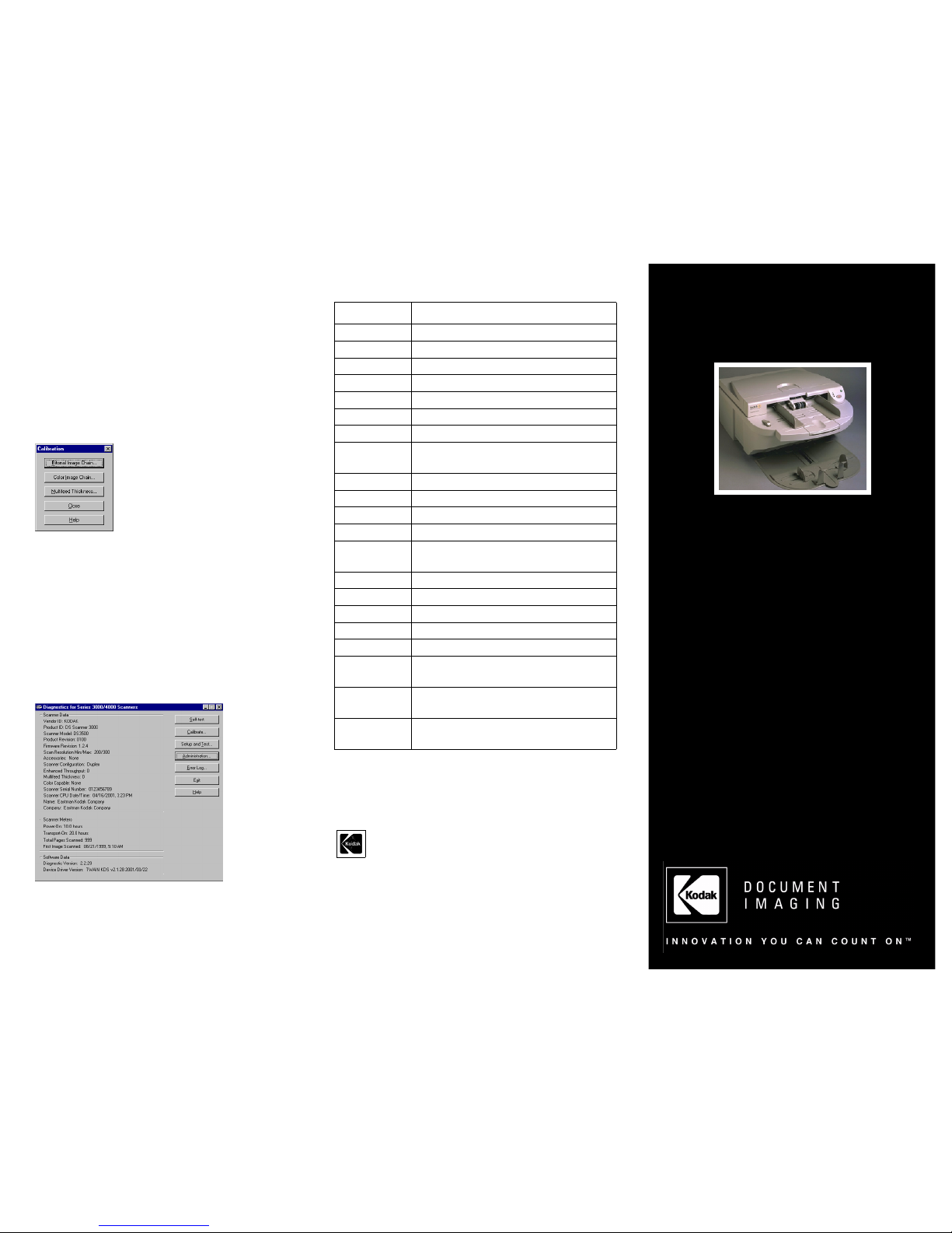
IMAGE CALIBRATION
Manual Calibration
1. Power on the scanner.
2. Wait 3 minutes for the exposure lamps to st abilize.
3. Press and hold the Pause button for 5 sec onds.
4. While still holding the Pause button, press the Resume button.
The transport starts.
5. Release both buttons and feed the Calibration Target into the
scanner to complete the image calibration process.
Diagnostic Calibration
1. From the main Diagnostics window, click Calibration.
2. Wait 3 minutes for the exposure lamps to st abilize.
3. Select the desired calibration.
Image Quality Issues?
Try the following:
1. Calibrate.
2. Clean the imaging guides.
3. Check the application settings.
4. Change the lamps.
5. Calibrate.
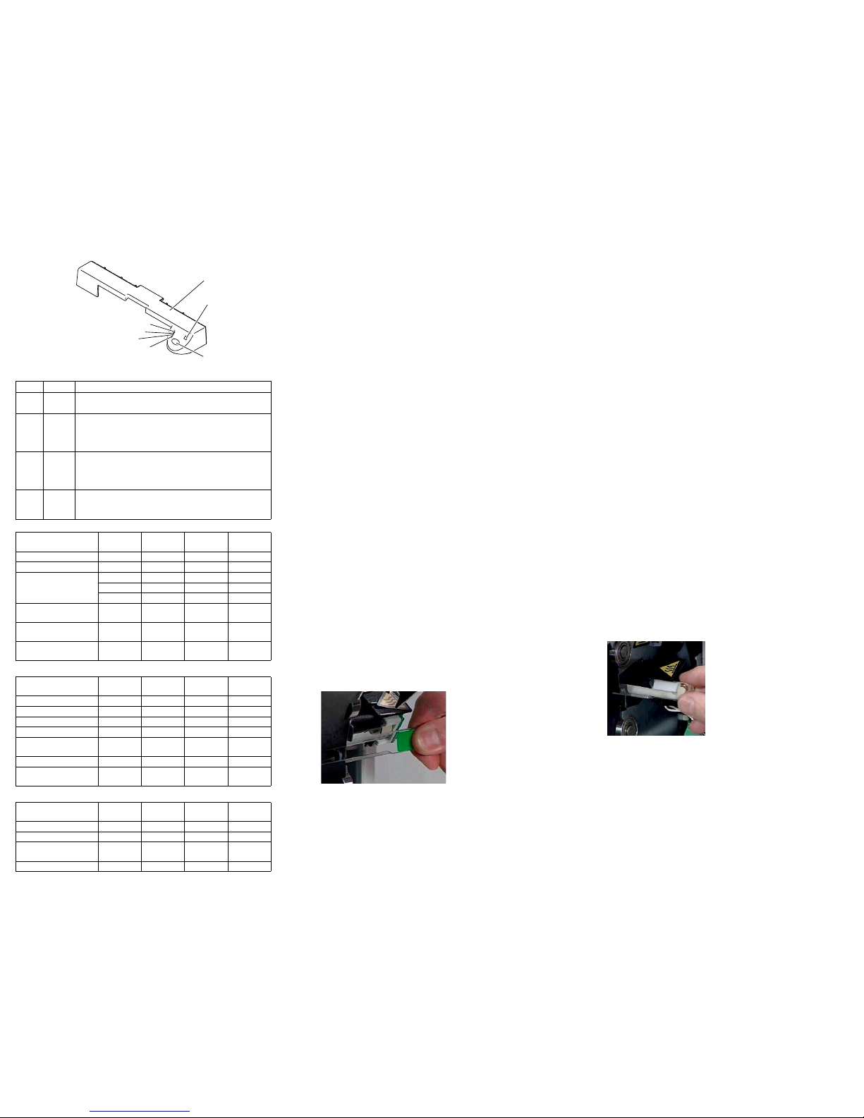
VIEW SCANNER ERRORS
Illuminated Red LED on Front Panel
Check the error log. Select “Error Log…” on the right side of
the main Diagnostics page.
COMMON PRODUCTION ISSUES
For additional troubleshooting tips, see the “Problem
Solving” tab in the Troubleshooting section of the User’s
Guide CD.
SUPPLIES*
* Items are subject to change.
Visit www.kodak.com for an updated listing of supplies.
Supplies can be purchased online at www.kodak.com through
shop@kodak.
EASTMAN KODAK COMPANY
Document Imaging
Rochester, New York 14650
Kodak and Digital Science are trademarks of Eastman Kodak Company.
©Eastman Kodak Company, 2001
Printed in USA 7/01
XP0042-1
Kodak Digital ScienceTM
SCANNER 3000 SERIES
Quick Tips
www.kodak.com
Kodak Field Service:
1-800-356-3253
Kodak Technical Assistance:
1-800-822-1414
Kodak Professional Services:
1-800-525-6325
Parts:
1-716-724-7274
Catalog No. Description
869 5519 Staticide Imaging Guide Wipes
853 5981 Emulsiclean Roller Cleaning Pads
169 0783 Transport Cleaning Sheets
986527 Calibration Targets
153 7240 150 Sheet Feed Module
159 2195 250 Sheet Feed Module
828 0604 Separator Roller
181 6826 150 Sheet Output Tray - Scanner
3500
876 7485 Extended Capacity Output Tray
876 7480 Enhanced Output Tray (250 sheet)
858 3858 Output Deflector
806 6318 Imaging Guide - Bitonal
153 7240 Front-reading Imaging Guide -
Scanner 3590C
108 5992 Imaging Guide - Scanner 4500
876 6545 White Imaging Lamp
126 0884 Red Dropout Lamp
132 9812 Green Dropout Lamp
800 1307 Blue Dropout Lamp
839 4306 Printer Ink Blotters -
Scanner 3520DP, 4500DP
838 4885 Printer Ink Cartridge Carrier -
Scanner 3520DP, 4500DP
854 6012 Maintenance Kit for 3000/4000
Series
LEDS ON THE OPERATOR PANEL
LED Descriptions
Power On Self Test (POST) Sequence
Normal Operation
Special Operations
CLEANING AND MAINTENANCE
POD
Lowering the POD
For more information, see “Lowering the POD” in the
Maintenance section of the User’s Guide CD.
1. Tur n off the scanner.
2. Disconnect the power cord from the back of the scanner.
3. Remove the output tray.
4. Move the scanner to the front edge of the work surface.
5. Firmly grasp the front of the POD with one hand, pull the
release latch and gently lower the POD. The POD does not
have to be completely lowered to change the feed module and
separator rollers.
FEED MODULE
Removing the Feed Module
For more information, see “Feed Module” in the Maintenance
section of the User’s Guide CD.
1. Do the “Lowering the POD” procedure above.
2. Grasp the feed roller assembly and push it toward the right.
3. Once the left side gear has cleared the feeder shaft, pull the
feeder assembly toward the front of the scanner.
Cleaning the Feed Module
Clean by using the Emulsiclean Roller Cleaning Pads.
SEPARATOR ROLLER
Removing a Separator Roller
For more information, see “Separator and Drive Rollers” in
the Maintenance section of the User’s Guide CD.
1. Do the “Lowering the POD” procedure above.
2. Open the access cover.
3. Grasp the middle of the roller and pull it away from the POD.
Cleaning the Separator Rol ler
Clean by using the Emulsiclean Roller Cleaning Pads.
IMAGING GUIDES
Removing the Imaging Guides
For more information, see “Imaging Guides” in the
Maintenance section of the User’s Guide CD.
1. Do the “Lowering the POD” procedure above.
2. Open the side access door.
3. Grasp the imaging guide behind the access door at the green
label and slowly pull the guide straight out.
4. Grasp the imaging guide at the green label on the POD side
and slowly pull the guide straight out.
Cleaning the Imaging Guides
Clean by using Staticide Imaging Guide Wipes.
CLEANING AND MAINTENANCE
PAPER PATH AND SENSORS
Cleaning the Paper Path
For more information, see “Paper Path and Sensors” in the
Maintenance section of the User’s Guide CD.
1. Remove the wrapping from the recommended Transport
Cleaning Sheet.
2. Adjust the feeder guides to fit the width of the sheet.
3. Feed the cleaning sheet (adhesive side up) twice through the
scanner in portrait orientation and twice in landscape
orientation.
4. Feed the cleaning sheet (adhesive side down) twice through
the scanner in portrait orientation and twice in landscape
orientation.
Note: When the cleaning sheet gets dirty, discard it and use a new
one.
Cleaning the Sensors and Reflector Strips
For more information, see “Paper Path and Sensors” in the
Maintenance section of the User’s Guide CD.
1. Remove the feed module.
2. Do the “Lowering the POD” procedure above.
3. Gently wipe the sensors with a clean, dry, lint-free cloth or
camel-hair brush.
4. Gently wipe the sensor reflector strip that is directly opposite
each sensor.
5. Close the POD firmly.
6. Install the feed module.
LAMPS
Caution: Lamps that have been operating are HOT. Make sure
the scanner is turned off, and allow it to cool for 10 minutes before
attempting to replace the lamps.
Removing the Lamps
For more information, see “Lamps” in the Maintenance
section of the User’s Guide CD.
1. Do the “Lowering the POD” procedure above.
2. Open the side access door.
3. Remove the imaging guides.
4. Use your thumb and forefinger to grasp the g reen handle of the
lamp connector.
5. Slightly raise the edge of the black holder and remov e the lamp
connector.
6. Grasp the lamp and slowly pull the lamp straight out.
Installing the Lamps
Important: Make sure that the clear surface of the lamp is facing
the imaging guide.
Color Name Function
Green Power Illuminated: Scanner is fully powered
Flashing: Scanner is in Lamp Saver Mode
Green Ready Illuminated: Scanner is ready to scan images
Flashing: Scanner is warming up
Not Illuminated: Scanner is in Idle Mode or is not
connected to the Host Computer
Y ellow Jam Illuminated: Scanner blockage/failure was detected during
power-up
Flashing: Scanner blockage/failure was detected during
scanning
Red Error/
Service
Illuminated: Do the steps in the Troubleshooting Guide
Flashing: A customer-recoverable error or fault condition
has occurred
System State Power Ready Jam
Error/
Service
Scanner is on Illuminated
Warm-up Illuminated Flashing
LED Cycle Illuminated
Illuminated Illuminated
Illuminated Illuminated Illuminated
LEDs on (followed by
beep)
Illuminated Illuminated Illuminated Illuminated
POST Successful:
Enter Idle Mode
Illuminated
POST Failure: Sensor
failure/Jam detected
Illuminated Illuminated
System State Power Ready Jam
Error/
Service
Idle Mode Illuminated
Scanning Enabled Illuminated Illuminated
Lamp Saver activated Flashing
Multifeed - at any time Illuminated Flashing
Hardware/Software
failure
Illuminated Illuminated
Buffer Full Flashing Flashing
Buffer Overflow/
Image Lost Error
Illuminated Flashing
System State Power Ready Jam
Error/
Service
Diagnostics in progress Illuminated Flashing
Calibration in progress Illuminated Flashing
Jam detected during
Scan/Calibrate
Illuminated Flashing
Calibration failure Illuminated Illuminated
B137_0090BC
B137_0090BCA
PAUSE BUTTON
LED
ERROR/SERVICE
JAM LED
READY LED
POWER LED
RESUME BUTTON
OPERATOR PANEL
 Loading...