

Page 1

3000DSV-E Digital Scanner-Printer
A-61371
Operator’s
Manual
Page 2

Safety Warnings
This section contains detailed instructions on the operation and maintenance of the Kodak 3000DSV-E Digital
Scanner-Printer. All operators should carefully read and follow the instructions in this manual.
The following section contains important information related to operator safety and may help prevent equipment
problems. Make sure you observe all of the precautions listed in this manual.
Warning symbols
• Do not modify this product, as a fire, electrical shock, or breakdown could result. If the product
employs a laser, the laser beam source could cause blindness.
• Do not attempt to remove the covers and panels, which have been fixed to the product. Some
products have a high-voltage part or a laser beam source inside that could cause an electrical
shock or blindness. The operator is only allowed to slide out/in the projection unit of the scanner.
• Only use the power cord supplied in the package. If a power cord is not supplied, only use the
power cord and plug that is specified in Power Cord Instruction. Failure to use this cord could
result in fire or electrical shock.
• Use only the specified power source voltage. Failure to do so could result in fire or electrical
shock. If you are in doubt, contact a qualified electrician.
• Do not use a multiple outlet adapter to connect any other appliances or machines. Use of a power
outlet for more than the marked current value could result in fire or electrical shock.
• Do not touch the plug of the power cord with a wet hand, as an electrical shock could result.
• Connect the plug of the power cord all the way into the power outlet. Failure to do this could result
in a fire or electrical shock.
• Do not scratch, abrade, place a heavy object on, heat, twist, bend, pull on, or damage the power
cord. Use of a damaged power cord (exposed core wire, broken wire, etc.) could result in a fire,
electrical shock or breakdown. Should any of these conditions be found, immediately turn OFF the
power switch, unplug the power cord from the power outlet, and then call your Kodak Service
Representative.
• Do not use an extension cord. Use of an extension cord could cause a fire or electrical shock.
Contact your Kodak Service Representative if an extension cord is required.
• Do not place a flower vase or other container that contains water, or metal clips or other small
metallic objects on this product. Spilled water or metallic objects dropped inside the product could
result in a fire, electrical shock, or breakdown.
• Should a piece of metal, water, or any other similar foreign matter get inside the product,
immediately turn OFF the power switch, unplug the power cord from the power outlet, and call
your Kodak Service Representative.
• If this product becomes inordinately hot or emits smoke, or unusual odor or noise, immediately
turn OFF the power switch, unplug the power cord from the power outlet, and then call your Kodak
Service Representative. A fire or electrical shock could result if you continue to use the product.
• If this product has been dropped or its cover damaged, immediately turn OFF the power switch,
unplug the power cord from the power outlet, and call your Kodak Service Representative. A fire
or electrical shock could result if you continue to use the product.
• Connect the plug of the power cord to a wall socket-outlet that is equipped with a grounding
A-61371 September 2004
terminal.
Page 3

Caution symbols
• Do not use flammable sprays, liquids, or gases near this product, as fire could result.
• Do not let any object plug the ventilation holes of this product. Heat could accumulate inside the
product, resulting in a fire or malfunction.
• Do not install this product at a site that is exposed to direct sunlight, or near an air conditioner or
heating apparatus. The resultant temperature changes inside the product could cause a
malfunction, fire, or electrical shock.
• Do not place the product in a dusty place, or a site exposed to soot or steam, near a kitchen
table, bath, or a humidifier. A fire, electrical shock, or breakdown could result.
• Do not place this product on an unstable or tilted bench, or in a location subject to a lot of
vibration and shock. It could drop or fall, causing personal injury or mechanical breakdown.
• After installing this product, mount it on a secure base. If the unit moves or falls, it may cause
personal injury.
• Do not store toner units and PC drum units near a floppy disk or watch that are susceptible to
magnetism. They could cause these products to malfunction.
• The inside of this product has areas subject to high temperature, which may cause burns. When
checking the inside of the unit for malfunctions such as a paper misfeed, do not touch the
locations (around the fusing unit, etc.) which are indicated by a “CAUTION HOT” label.
• Do not place any objects around the power plug, as the power plug may be difficult to pull out
when an emergency occurs.
• The wall socket-outlet shall be installed near the machine and shall be easily accessible as the
power plug may be difficult to pull out when an emergency occurs.
• Always use this product in a well-ventilated location. Operating the product in a poorly ventilated
room for an extended period of time could injure your health. Ventilate the room at regular
intervals.
• Whenever moving this product, be sure to disconnect the power cord and other cables. Failure to
do this could damage the cord or cable, resulting in a fire, electrical shock, or breakdown.
• When moving this product, always hold it by the locations specified in the Operator's Manual. If
the unit falls, it may cause severe personal injury. The product may also be damaged or malfunction.
• When unplugging the power cord, be sure to hold onto the plug. Pulling on the power cord could
damage the cord, resulting in a fire or electrical shock.
September 2004 A-61371
Page 4

Routine Precautions
• Do not store toner units, PC drum units, and other supplies and consumables in a place subject
to direct sunlight and high temperature and humidity, as poor image quality and malfunction could
result.
• Do not attempt to replace the toner unit and PC drum unit in a place exposed to direct sunlight. If
the PC drum is exposed to intense light, poor image quality could result.
• Do not unpack a toner unit or PC drum unit until the time of use. Do not leave an unpacked unit
standing. Install it immediately or poor image quality could result.
• Do not keep toner units and PC drum units in an upright position or upside down, as poor image
quality could result.
• Do not throw or drop a toner unit or PC drum unit as poor image quality could result.
• Do not use this product in an area where ammonia or other gases or chemicals are present.
Failure to do so may shorten the service life of the product, cause damage or decrease
performance.
• Do not use this product in an environment with a temperature outside the range specified in the
Operator's Manual, as a breakdown or malfunction could result.
• Do not attempt to feed stapled paper, carbon paper or aluminum foil through this product, as a
malfunction or fire could result.
• Do not touch or scratch the surface of the toner unit developing roller and the PC drum, as poor
image quality could result.
• Use the supplies and consumables recommended by the dealer. Use of any supply or
consumable not recommended could result in poor image quality and breakdown.
A-61371 September 2004
Page 5

1 Introduction
This Operator’s Manual provides information and procedures for using
the Kodak 3000DSV-E Digital Scanner-Printer. Following is a summary
of what is included:
Chapter 1, Introduction — provides general information about the
Kodak 3000DSV-E Digital Scanner-Printer including a product
description, installation information, environmental specifications, an
overview of external components, and how to turn the scanner on and
off.
Chapter 2, Control Panel and Functions — provides a list of the
icons found on the Operator Control Panel and what functions can be
performed using the Operator Control Panel.
Chapter 3, Using the Scanner — provides procedures on how to use
the scanner, including selecting and installing the lens, zooming and
focusing images, rotating images, selecting the paper size, print
position and image density, adjusting the image processing features
and how to print and scan the displayed image.
Chapter 4, Printer Functions — provides general information about
the printer including an overall description of external components, use
and care of the printer and printer supplies.
Chapter 5, Maintenance — provides maintenance procedures for the
scanner, including replacement procedures for replacing the projection
lamp.
Chapter 6, Troubleshooting/Messages — provides information on
analyzing and correcting operating/printing problems or errors. Also
provides procedures for clearing paper misfeeds in the printer.
Appendix A — provides specifications for the Kodak 3000DSV-E
Scanner and A3/A4 Laser Printer.
Appendix B — user and system settings can be changed by you or
your Kodak Service Representative. This appendix provides the factory
settings and a description of those settings.
Appendix C — provides Key Operator information along with a chart
that you can record system information, such as scanner/printer model,
accessory names and serial numbers.
A-61371 September 2004 1-1
Page 6

Product description The Kodak 3000DSV-E Digital Scanner-Printer scans images and
outputs to the optional Video Laser Printer through a built-in PC
interface. The 3000DSV-E Scanner is ideal for medium-high volume
scanning of all formats of media from microfiche, jackets, aperture
cards, 16 and 35 mm roll film and 16 mm M and ANSI cartridges.
Installation Placement of the unit in the environment described below will ensure
optimal performance throughout the long life of service for which it was
designed.
• A well-ventilated place.
• An area which is free from ammonia or other organic gases.
• A place which has easy access to a power wall socket-outlet so that
the unit may be easily plugged in and unplugged.
• Any area free from direct sunlight.
• A place which is out of the direct air stream of an air conditioner,
heater or ventilator and is not subject to extremely high or low
temperatures or humidity.
• A stable location with a flat surface that is not subject to undue
vibration.
• A place that is free from any object that would block the heat exhaust
duct of the printer.
• A place away from curtains or anything else that is easily flammable.
• An area that is safe from spilled water or other liquids.
• A dust-free location.
NOTE: If the scanner is located near a window, do not face the screen
towards the window.
1-2 A-61371 September 2004
Page 7

Power source The power source voltage requirements are as follows:
• Use a power source with minimal voltage fluctuation.
Power Source: 50Hz-60Hz
Voltage fluctuation: within ± 10%
Frequently fluctuation: within ± 3%
NOTE: If you are in doubt, call a qualified electrician.
• The outlet should be located near the unit and be easily accessible
so that the power cord can be unplugged immediately if necessary.
• NEVER connect any other appliances or machines by means of a
multiple socket to the outlet being used for the unit.
• Make sure that the power cord and extension cord do not become
caught in any mechanism of the system. Do not allow either the
power or extension cord to become caught underneath the weight of
the unit.
Grounding To prevent electrical shocks caused by electrical leakage, always
ground the printer. Connect the grounding wire to:
In the United States:
• Connect the grounding wire to:
- The ground terminal of the outlet.
- A grounding contact that complies with the local electrical
standards.
• A grounding contact that complies with the local electrical standards.
• NEVER connect the grounding wire to a gas pipe, the grounding wire
for a telephone, or a water pipe.
A-61371 September 2004 1-3
Page 8
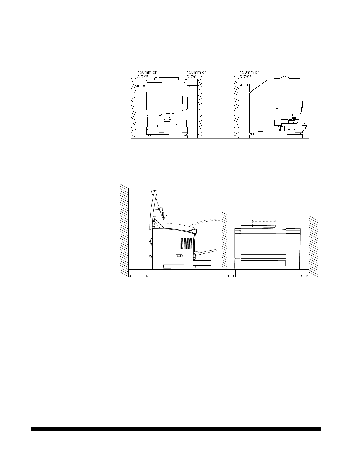
Space requirements Scanner:
The illustration below provides the clearance dimensions between the
wall and the rear of the unit as well as the right and left sides which
provide ample space for the ventilation ports to dissipate heat.
System Printer (A3/A4 Laser Printer):
For ease of operation, maintenance and replenishment of supplies, the
minimum clearance shown below is required. Install the unit in an area
that allows easy access.
150mm
5-7/8"
150mm
5-7/8"
150mm
5-7/8"
1-4 A-61371 September 2004
Page 9

Operating environment
The environmental requirements for operating the system are as
follows:
Temperature: 10° to 35°C (50 to 95°F) with a fluctuation of 10°C
(18°F) per hour.
Humidity: 15 to 85% with a fluctuation of 20% per hour.
System configuration This scanner is available in the following configurations:
Printer mode (connected to the A3/A4 Laser Printer)
The scanner is connected to a dedicated printer, allowing scanned
images to be printed out directly.
PC mode (connected to a personal computer)
The scanner is connected to a personal computer and the scanned
images can be uploaded to the computer.
Connection to a personal computer and printer can be switched using
the control panel.
A-61371 September 2004 1-5
Page 10

3000DSV-E Scanner components
Following is a list of the standard components of the 3000DSV-E
Scanner:
Front view
1
2
7
3
4
8
5
2
6
1 Screen — the image from the film is displayed for viewing on the
screen. The frame on the screen marks the data reading range.
2 Control Panel — most operations are controlled from the keys
and indicators on the control panel. See Chapter 2, Control
Panel and Functions for more information.
3 Image Rotation Knob — use this knob to rotate the image on
the screen.
4 Projection Lens (optional) — several projection lenses are
available to change the size and adjust the focus of the image.
For more information on the projection lenses, see the next
section.
5 Fiche Carrier 5 (optional) — supports the viewing of
microfiche.
6 Projection Lamp Unit — contains the Projection Lamp
(halogen lamp) which projects the film image onto the screen.
7 Printer Connector — Connects the scanner to the printer
through an interface cable.
8 SCSI Connector — Connects the scanner to the Personal
Computer through a SCSI cable.
1-6 A-61371 September 2004
Page 11

Rear view
9
10
12
13
11
9 Power Switch — used to turn the power to the unit on and off.
10 Connectors — provides connection points for the various
options (Film Carrier and Controller).
11 Power Cord Socket — plug the power cord furnished with the
scanner into this socket.
12 Total Counter — shows the total number of prints made
regardless of paper size.
13 Power Cord — connects the scanner to the power wall socket-
outlet.
A-61371 September 2004 1-7
Page 12

3000DSV-E Scanner optional accessories
Optional accessories are available for the scanner such as different
projection lenses, film carriers, and auto retrieval controllers. The
optional accessories are listed below. Contact your Kodak
Representative for more information about these accessories.
Projection Lenses - several projection lenses are available to change
the size and adjust the focus of the image. Four lenses are available:
Single lens 7.5X
Zoom lens 9-16X
Zoom lens 13-27X
Zoom lens 23-50X
Auto-retrieval Controllers
Mini Mars-2 Controller — for automatic
reading of 16 mm Cartridge Microfilm using
up to 2-level image marks.
Mars IV Controller — for automatic
reading of 16 mm Cartridge Microfilm using
up to 3-level image marks.
Both controllers may be used in conjunction with the RFC-15A,
RFC-15M or RFC-21A/M Carriers.
1-8 A-61371 September 2004
Page 13

Film carriers
Fiche Carrier-5 — for use with jackets,
microfiche and aperture cards.
RFC-9B — a motorized carrier for semiautomatic loading of 16 and 35 mm open
spool film.
UC-2 — a motorized carrier for semiautomatic loading of 16 and 35 mm open
spool film, microfiche, aperture cards,
jackets.
RCF-15A — for automatic loading of 16
mm ANSI Clip Cartridge Microfilm (Open
Spool Adapter option).
RCF-15M — for automatic loading of 16
mm 3M Type Cartridge Microfilm.
RCF-21 — for automatic loading of 16 mm
ANSI or 3M Type Cartridges. This carrier is
designed for very high-speed 16 mm film
searching.
ACF7 — for automatic loading, viewing and
ejection of aperture cards and works in
medium- to high-volume applications.
A-61371 September 2004 1-9
Page 14

Turning the power on
Following are procedures for turning the scanner power on and off.
and off
Power On
• Press the power switch of the scanner to the on (I) position.
- For PR mode, turn on the power to the scanner only.
- For PC mode, turn on the scanner and the power to the Personal
Computer.
The indicators on the Control Panel light up and the system starts
the initialization operation. When the wait indicator goes out, the
system is ready for printing.
Wait symbol
NOTE: If you load the film in the Film Carrier and press Start while
the printer is warming up, you can scan and memorize the
film image of about 9 pages (letter or A4 size/400 dpi). The
printer allows that print process to be started as soon as the
printer completes warming up.
Both ends of the Exposure display blink. If you want this
function disabled, contact your Kodak Service
Representative.
1-10 A-61371 September 2004
Page 15

To turn the power off
• Press the Power switch of the scanner to the O (Off) position.
Auto Power Save/ Projection Lamp functions
This system provides two functions that help to decrease power
consumption:
• The Auto Power Save function that automatically shuts down power
to the printer heater.
• The Auto Projection Lamp OFF function that automatically turns off
the Projection Lamp of the scanner.
Both are activated when the system is left idle for a specified period of
time.
These functions may be disabled or enabled. When enabled, timing
can be selected from either 30 or 60 minutes. The default for both of
these functions is Disabled. Contact your Kodak Service
Representative for more information.
When the system is in the Auto Power Save mode, each outside
segment of the Multi-Print Display LEDs light up sequentially.
A-61371 September 2004 1-11
Page 16

2 Control Panel and Functions
Following are descriptions of the Control Panel functions. Some
functions are available by using the Shift key and some of the functions
provide access to optional accessories. This chapter provides an
overview of each function.An overview of the image processing
features are also described in this chapter. Chapter 3, Using the
Scanner, provides procedures on how to use each function.
Control Panel - Standard
12
Paper Selection
A3
A4
A4
Paper Selection
11×17
1
/
2
8 ×11
1
2
/
8 ×11
6
1
/
2
8 ×14
Ohter
78
Exposure
Auto
Darker
Lighter
9
11 15
Start10 1 C
12 13 1410
1
Print Position
Print Mode
Film Type
2
3
Auto
Nega
Posi
Text
Fine
Photo
45
1 Memory Input Key — to store one of the following functions into
the memory of the scanner, first set one of the functions on the
Control Panel and then press this button with the head of a pen or
other device. The next time the scanner is turned on, that function
will appear as a default setting until a new one is entered. A
maximum of three settings can be memorized.
• Negative or positive
• Print mode
• Print position*
• Paper size
• Print image density
• Exposure mode
• Centering or Fit
• Manual Masking
• Auto Masking
• Auto Skew Correction
• Horizontal Area setting
• Vertical Area setting
• Electrical Zoom magnification
• Resolution
• Image Distortion Correction
*If the current paper tray or cassette is different from the paper tray/cassette that is
loaded when the Paper size setting was made, Center Image Print is selected for
the print position and the current paper size is selected.
NOTE: If you do not press the Memory Input key within 60 seconds
after a setting has been made with the Auto Reset function set
to On, the previous setting remains valid.
A-61371 September 2004 2-1
Page 17

2 Lamp Illuminance key — manually adjusts the Projection Lamp
illuminance. When the Projection Lamp is Off, it can be turned On
again by pressing any key.
3 Film Type key — rotates between Auto, Nega, and Posi each time
the key is pressed.
Auto: The scanner automatically determines between the film type
options of negative or positive for print production.
Nega: Select when using negative film. Dark and light values of the
print will be reversed.
Posi: Select when using positive film. Dark and light values of the
print will be consistent with the image on film.
4 Print Mode Key — allows you to fine-tune the image quality of the
print according to the original being used. Rotate between Text,
Fine and Photo with every press of this key.
Text: For use with text images.
Fine: For use with lower grades of film.
Photo: For use with photo images.
5 Print Position Key — selects the portion of the image displayed
on the screen to be printed.
Center: The image in the center of the screen is
printed.
Left: The image on the left half of the screen is
printed.
Page-by-Page: The images on both the left and right
12
sides of the screen are printed consecutively on
8 1/2 x 11" (A4) sheets of paper.
This option is only available when 8-1/2 x 11" (A4)
paper is selected.
6 Paper Selection Key — allows you to select either PC or PR
mode.
PC mode: selects the scanning size.
PR mode: selects the size of paper to be used for printing. When
the paper feeding tray is loaded with 8 1/2 x 11” (A4) paper and the
paper in the paper cassette contains 11 x 17” (A3) paper, pressing
this key rotates through the Auto, Paper Feeding Tray, and Paper
Cassette options. Both the 8 1/2 x 11” (A4) and 11 x 17” (A3)
indicators will illuminate when Auto is selected.
7 Exposure Display — indicates the current density level of the
printed image.
8 Exposure Mode Indicator — Auto Exposure mode is indicated
when the green Auto light is on. The green Auto light turns off when
the scanner is in the Manual Exposure mode.
2-2 A-61371 September 2004
Page 18

9 Exposure Mode Key — press to select between the Auto or
Manual Exposure modes.
10 Exposure Adjustment Keys — adjusts the density of the image to
be printed during the Auto or Manual Exposure mode.
• Darker: supports darker image density.
• Lighter: supports lighter image density.
11 Multi-Print Display — displays the number of prints to be made.
Also displays corresponding codes in the event of a malfunction or
paper misfeed. The blinking number in this display indicates the
print cycle in progress.
12 Multi-Print Keys — used to input the number of prints to be made.
This function is only available in the PR mode.
• 10: increases the number of prints to be made in increments of
10 (10, 20, 30 ...90, etc.)
• 1: increases the number of prints to be made in increments of 1
(1, 2, 3 ... 9, etc.)
13 Clear/Stop Key — clears the setting on the Multi-Print Display,
resets the display to 1 or stops a multi-print cycle. This function is
only available in the PR mode.
14 Start Key — starts the print (scan) process of the displayed image.
15 Indicators:
Misfeed/Call Kodak indicator: lights up when a paper
misfeed or malfunction occurs.
Wait indicator: lights when the scanner is initializing
and when the printer is warming up.
Closure Failure indicator: lights up if the printer cover
is open.
Add Toner indicator: blinks when the imaging
cartridge of the printer is running out of toner and lights
up when the cartridge is completely out of toner.
Add Paper indicator: lights up when the printer is not
loaded with the selected paper size or when either the
Paper Feeding Tray or Paper Cassette has run out of
paper with Auto Paper selected.
A-61371 September 2004 2-3
Page 19

Using the Shift function on the Control Panel
When you use the Shift function (Clear/Stop key) on the Control Panel,
other options are available.
Control Panel - Shift Function
Paper Selection
A3
A4
A4
Exposure
Lighter Darker
Auto
3
4
12
Paper Selection
11×17
1
/
2
8 ×11
1
/
2
8 ×11
1
/
2
8 ×11
Other
Film Type
Job Recall Resolusion Zoom- Zoom clr Zoom+ Shift PC/PR
Auto
Nega
Posi
Text
Fine
Photo
1
2
Print Position
Print Mode
NOTE: All of these functions can be performed when the Shift key and
one of the keys described below are pressed.
1 Job Recall — when this key is pressed together with the Shift key,
the program registration locations (1J, 2J and 3J) are called. Each
time this key is pressed while the Shift key is held down, the display
rotates through 1J, 2J and 3J.
2 Resolution —
sets the resolution of the scanner.
• When the scanner is connected to the printer, available
resolutions are: 400 dpi (4H) and 600 dpi (6H).
• When the scanner is connected to the PC through PowerFilm
Application Software, available resolutions are: 200, 300, 400,
600 and 800 dpi (2H, 3H, 4H, 6H and 8H respectively).
3 Zoom - sets zoom magnification.
Start10 1 C
5
• Zoom+: when Zoom+ is pressed with the Shift key, the
magnification is increased by an increment of 0.0IX (up to
2.00X).
• Zoom clr: clears the current zoom setting when this key is held
down together with the Shift key for one second.
• Zoom-: when Zoom- is pressed with the Shift key, the
magnification is decreased by a decrement of 0.01X (down to
0.50X).
4Shift — the Shift key must be pressed when you want to access
one of the functions described in this section: Lamp Illumination,
Resolution, Job Recall, Zoom or PC/PR.
5 PC/PR — when selected (with the Shift key) the connection to the
PC or printer is selected. This key is not valid unless the PC
interface cable is connected to the PC.
2-4 A-61371 September 2004
Page 20

Control Panel
Centering/Fit
1 5 62 3 4
Masking Auto
Masking
1 Centering/Fit key — when pressed, enables or disables the
Centering and Fit functions. When Auto Masking, Trimming or
Masking are set to Off, Auto Masking will automatically be enabled
when Centering is selected.
2 Masking — when pressed, cycles through Off, Trimming, Masking
if the system has the optional Manual Masking Kit.
Auto Skew
Correction
Focus AF
Centering: centers all masked images onto the printed
page.
Fit: enlarges the displayed image to fill the page when
printed. Enlargement is only to the full length or width
of the paper, whichever is achieved first.
Off Indicates no masking or trimming will be done.
Masking: prints only the image outside of the area that
is defined on the screen.
Trimming: prints only the area of the image that is
defined on the screen.
• If Trimming is selected from the Off state, the
previously entered settings for Centering/Fit and
Manual Masking are applied.
• From Trimming, when Masking is selected, the
Centering/Fit setting is disabled and the previous
settings for the Masking area are applied.
• The Manual Masking area will be cancelled whenever
Off is selected from the Masking state.
• Trimming or Masking are not available through the
Auto Masking function.
A-61371 September 2004 2-5
Page 21

3 Auto Masking Key — turns auto masking on or off. Auto masking
omits the frame (non-image area) of a printed film image. Auto
masking is only available in the PR mode.
• The previous Centering/Fit setting is applied when On is
selected from the Off state.
• If Off is selected from the On state, Centering/Fit is disabled.
• Auto Masking is not applicable with Masking or Trimming.
4 Auto Skew Correction key — turns auto skew on or off.
When auto skew is on, the indicator is lit and any skew of the
image will be corrected during printing.
After printing, the skew is retained by default. Contact your Kodak
Service Representative to change the default.
5 Manual Focus keys — press the up or down arrow keys to
manually adjust the focus of the displayed image.
6 AF (Auto Focus) key — when pressed the system automatically
finds the optimum focus for the displayed image. When the image
is in focus, the Auto Focus LED will turn off.
NOTE: If an image in not properly centered or the contrast and
density of the image is such that it causes the Auto Focus
to error, the LED will blink. The LED will turn off when the
Manual Focus keys or the Auto Focus key is pressed.
2-6 A-61371 September 2004
Page 22

Image Processing features
This section provides a description of the image processing features.
Procedures on how to use these features can be found in Chapter 3,
Using the Scanner.
Screen image to Print Image Description
Auto Masking (1 Frame)
The black borders that run along the edges
of the image are masked.
Trimming (1 Frame)
Trimming (2 Frames) When 11 x
17” (A3) is selected.
Masking (1 Frame)
Masking (2 Frames) When
11 x 17” (A3) is selecte
d.
Everything but the center of the image is
masked.
The frames surrounding the center of both
images are masked. The Manual Frame
Masking Kit is required.
The center of the image appearing on the
screen will be masked. The Manual
Masking Kit is required.
Two areas of the center of the image
appearing on the screen will be masked.
The Manual Masking Kit is required.
Auto Centering
Auto Skew Correction
An image is generated that is centered on
the printed page from the displayed image
with a masked frame.
Automatically corrects any skew when the
image is printed.
A-61371 September 2004 2-7
Page 23

Screen Image to Print Image
Page-by-Page Print
Description
The system takes two film images that
appear side-by-side on the screen and
prints them on separate 8 1/2 x 11” (A4)
sheets of paper.
Auto Paper Select Print
Text Imprint
1234ABCD January 1, 2001
1234ABCD January 1, 2001
Image Distortion
The system automatically detects either
half-size or full-size film to determine the
size of paper for printing (half-size film is
printed on 8 1/2 x 11” (A4) portrait paper,
full-size film is printing on 11 x 17” (A3)
landscape paper.
Time, date and messages can be included
on a print. To enable this function, contact
your Kodak Representative.
The system automatically corrects slight
image distortion that can occur during
scanning.
2-8 A-61371 September 2004
Page 24

3 Using the Scanner
This chapter provides procedures on how to us the Kodak 3000DSV-E
Scanner.
Following is an outline of the basic printing procedure. Detailed
procedures on these steps can be found later in this chapter.
1. Load the film. The procedure for loading film is determined by the
type of Film Carrier (optional) that is being used. Review the
Operator’s Manual that came with your Film Carrier for more
information.
2. Select and replace the lens.
3. Select the connection mode.
4. If desired, zoom, focus or rotate the image.
5. Select the paper size. If both 8 1/2 x 11” (A4) and 11 x17” (A3) are
loaded, the system can select the correct size automatically.
6. Select the print position.
7. Select the image density.
8. Enter the number of prints to be made.
9. Adjust the image processing features.
10.Print and scan the displayed image. The printing or scanning of the
image appearing on the screen is initiated after the Start key is
pressed.
A-61371 September 2004 3-1
Page 25

Selecting a projection lens
Film Scanning Size
35mm
16 mm
Source
Document
COM
Projection lenses are available in the following types. Select the type of
lens that corresponds to the film you are using.
1 Type 1: 7.5X
2 Type 1: 9 x 16X
3 Type 2: 13 to 27X
4 Type 3: 23 to 50X
The list below shows the standard types of film and the recommended
zoom ratios of lenses to be used with the system printer. The size and
format of one frame of film may vary depending on the shooting
conditions.
11 x 17” (A3) 8 1/2 x 11” (A4) B4 3 2/3 x 8 1/2”
Half 2 or 3 2 2 2
Full211-
Half 4 3 3 3 or 4
Full 3 or 4 2 2 2 or 3
60 3 or 4 3 3 3 or 4
98 4 3 or 4 3 or 4 4
325- 444
420 - 4 4 -
63 3 or 4 3 3 3 or 4
70 3 or 4 3 3 3 or 4
80 4 3 or 4 3 or 4 4
84 4 3 or 4 3 or 4 4
120 4 3 or 4 3 or 4 4
208 4 4 4 4
270- 444
Zoom the lens in and out to find the optimum ratio that will fit the
scanning size.
3-2 A-61371 September 2004
Page 26

Installing the projection lens
To install a lens with a magnification different from the pre-installed
lens.
1. Grasp the Prism Holder lever and pull it up.
2. Pull out the projection lens unit.
3. Slide the desired projection lens unit into the scanner along the lens
holder guide.
NOTE: When the projection lens unit is slid into position, the
scanner automatically selects the optimum screen
brightness according to the type of lens being used.
A-61371 September 2004 3-3
Page 27

Positioning the film image
The size frame markers that correspond to the scanning size are
marked on the screen. Through zooming and image rotation, and by
operating the film carrier mounted on the system, position the image on
the screen so the image fits in the scanning size.
Size Frame
11 x 17” or A3 size 8 1/2 x 14” size
8 1/2 x 11” or A4 size
Vertical Horizontal
3-4 A-61371 September 2004
Page 28

Zooming and
Zooming in on the displayed image:
focusing images
• Rotate the Zooming Ring dial to bring the image on the screen into
the print size frame.
Focusing the displayed image:
• Center the displayed image and press the AF (Auto Focus) key to let
the scanner automatically bring the image into focus.
Focus AF
NOTE: You can use the Focus (manual focus) keys to manually adjust
the focus of the displayed image.
Rotating images To rotate the image on the screen:
• Turn the Image Rotation knob until the image is displayed at the
desired rotation. The greater the turning angle of the Image Rotation
knob, the faster the turning speed.
NOTES:
• If you hold down the Shift key and turn the Image Rotation knob, the
image quickly rotates by 90 degrees.
• If Auto Skew Correction is turned on, the system automatically
corrects any skew of the image when printed. When Auto Skew
Correction is on, the indicator is lit.
A-61371 September 2004 3-5
Page 29

Selecting the film
Auto
type
The system will automatically determine the polarity of the film being
used when Auto is selected with the Film Type key.
NOTE: The system cannot determine the polarity of certain types of
film. If the system cannot detect a film type, select it manually.
Nega (Negative film)
If negative film is being used, press the Film Type key to select Nega.
Posi (Positive film)
If positive film is being used, press the Film Type key to select Posi.
3-6 A-61371 September 2004
Page 30

Selecting the paper size
Press the Paper Selection key to select the desired print size. The
system cycles through the available sizes each time you press the key.
Using the Auto Paper Selection function
When the Paper Feeding Tray is loaded with 8 1/2 x 11” (A4) paper and
the paper cassette is loaded with 11 x 17” (A3) paper, this function can
be used to automatically select the appropriate size of paper for the
current job.
• Press the Paper Selection key so both the 11 x 17” (A3) and the
8 1/2 x 11” (A4) LEDs light up.
The system automatically detects the image area and prints on
8 1/2 x 11” (A4) paper for half-size film and on 11 x 17” (A3) paper for
full-size film.
Film Image
Half Full
Print Image
8 1/2" x 11" (A4) 11" x 17" (A3)
NOTES:
• The Auto Paper Selection function can only be used for a
combination of 11 x 17” (A3) and 8 1/2 x 11” (A4) paper sizes. The
Page-by-Page function cannot be selected when the Auto Paper
Selection capability is being used.
• When a 7.5x lens is being used, the Auto Paper Selection function
cannot use 11 x 17” (A3) size paper because of the size of the image
area.
• When Masking or Trimming has been previously selected, the
system selects 8 1/2 x 11” (A4) if the defined area is less than 8 1/2 x
11” (A4) size and 11 x 17” (A3) for all other print jobs.
A-61371 September 2004 3-7
Page 31

Using the Auto Film Format Selection function
When the paper feeding tray is loaded with 8 1/2 x 11” (A4) paper and
the paper cassette is loaded with 8 1/2 x 11” (A4) paper, this function
can be used to automatically select the appropriate size of paper for the
current print job.
1. Press the Paper Selection key so both the 8 1/2 x 11” (A4) and the
8 1/2 x 11” (A4) LEDs light up.
2. Press the Start key. The system automatically detects the image
area and prints on 8 1/2 x 11” (A4) paper for portrait film and on
8 1/2 x 11” (A4) paper for landscape film.
Portrait
Landscape
Selecting the Print Position
Center
• The system prints the image that
appears in the center of the screen.
Left
• The system makes a print of the
image that appears on the left side of
the screen.
Page-by-Page
• The system prints the images that
appear on both the left and right sides
of the screen on separate sheets of
8 1/2 x 11” (A4) paper.
NOTE:Only 8 1/2 x 11” (A4) paper can be
selected for Page-by-Page.
3-8 A-61371 September 2004
Page 32

Selecting the image
Using Auto Exposure
density
1. Press the Exposure Mode key to select the Auto Exposure mode.
2. If the Auto Exposure setting is not satisfactory, press the appropriate
Exposure Adjustment key, either Lighter or Darker, to set the
desired image density.
Using Manual Exposure
1. Press the Exposure Mode key and select the Manual Exposure
mode.
Entering the number of prints to be made
2. Press the appropriate Exposure Adjustment key, either Lighter or
Darker, to set the desired image density.
Entering a number from 1-9
• Enter the desired number of prints using the Multi Print key “1”.
If the “1” key is pressed when “9” is displayed, the number on the
display is incremented by one: 10, 11, 12, etc.
Entering a number from 10- 99
1. Set the tens digit using the “10” key.
2. Set the units digit using the “1” key.
For example, to set “25” press the “10” key twice and press the “1” key
five times.
A-61371 September 2004 3-9
Page 33

Correcting a number
To reset an entry:
• Press the Clear/Stop key, which resets the number on the Multi-Print
display to “1”.
Using Auto Masking The Auto Masking function prevents the frame (non-image area) of a
film image from appearing on the print.
Selecting Auto Masking
• Press the Auto Masking key to turn on this function.
Correction
Operating Conditions for Auto Masking
A
B
A
B
B
B
• The image area of the screen must provide at least 45 mm
horizontally and vertically.
• The width of the frame to be masked must be at least 10 mm.
NOTE: If the film image on the screen does not meet the above
requirements, the Auto Masking function will not work properly.
Auto Masking is a frame erasing feature, it cannot remove an
image from in between two separate frames.
AB AC
3-10 A-61371 September 2004
Page 34

Manual Masking panels
4
L
(option)
1
engthwise
Area Keys
2
3
Crosswise Area Keys
1 Lengthwise Area Indication panel — use to specify the print area
in the vertical direction of the image on the screen. The system
makes a print of the image corresponding to the way the Area keys
are illuminated. A total of 42 Area keys are placed at 7 mm intervals.
2 Lengthwise Area Clear key — press to clear any print area
previously defined in the vertical direction.
3 Crosswise Area Clear key — press to clear any print area
previously defined in the horizontal direction.
4 Crosswise Area Indication panel — use to specify the print area in
the horizontal direction of the image on the screen. The system
makes a print of the image corresponding to the way the Area keys
are illuminated. A total of 61 Area keys are placed at 7 mm intervals.
NOTE: When 11 x 17” (A3) and Page-by-Page are selected, all keys
light up except those on the right and left ends. The keys on the
right and left ends are invalid for the Manual Masking panels.
A-61371 September 2004 3-11
Page 35

Using Manual Masking
The optional Manual Masking Kit allows you to specify an area of
printing of the displayed image through two separate features: trimming
and masking.
Selecting Trimming
• Press the Masking key to select Trimming. The lights on the panel
light up according to the currently selected paper size and print
position.
ON
Example: A4 vertical, Center
A4 vertical,
Center
ON
NOTE: You can print the area specified by the green lights.
Defining an area
Define the end points for both the vertical and horizontal areas of the
image on the screen using the green lights on the area indication
panels.
3
4
1
2
NOTE: The points defining the vertical and horizontal area can be
selected in any order. Blinking lights on the indication panels
indicate an improper entry of the specified area.
3-12 A-61371 September 2004
Page 36

Defining two separate areas
Define the areas to print by specifying the vertical and horizontal areas
as follows: 2 end points for vertical and 4 end points for horizontal.
5
6
12 34
NOTE: The points defining the vertical and horizontal area can be
selected in any order. Blinking lights on the indication panels
indicate an improper entry of the specified area.
Defining Page-by-Page Print Area
• Using the vertical and horizontal points on the Area Indication panels,
define the print areas of the image on the screen.
5
6
A
1
2
34
NOTES:
• The horizontal indicator marked A does not light up and cannot be
used for defining an area.
• Four different areas cannot be defined on a single page.
• If the Area keys start blinking when the Print key is pressed, it
indicates that the print area defined is not available. Specify the area
again.
• Paper must be 11 x 17” (A3) when defining two areas and 8 1/2 x 11”
(A4) when defining Page-by-Page print areas.
• Paper can be of any size when defining one area.
• The print area, once defined, is stored in memory for each paper size
and print position. Press the Area Clear key to clear the area setting.
A-61371 September 2004 3-13
Page 37

Clearing a defined Print area
• Press the Vertical and Horizontal Clear keys.
Selecting Masking
• Press the Masking key to select Masking when you want to mask a
given area of an image.
NOTE: The basic operation for Manual Masking is similar to Trimming.
Refer to the previous procedures on Trimming and defining
areas for instruction on performing Manual Masking.
Using Centering and Fit
Once the image on the screen has been manually trimmed or auto
masked, the Image Centering function moves the image to the center of
the print. The Fit function however, fits the image on the screen onto the
entire surface of the print.
Screen Image Print Image
Centering Off
Centering
On
Centering
Fit Off
Fit On
Fit
3-14 A-61371 September 2004
Page 38

Centering
• Press the Centering/Fit key to turn on Centering.
Centering/Fit
NOTE: Centering/Fit mode cannot be used if Masking is selected.
Fit
• Press the Centering/Fit key to turn on Fit.
Centering/Fit
Using the Cycle Print Mode
NOTE: Fit mode cannot be used when the scanner is connected to the
PC.
This function automatically scans the next image following a preset
period of time. Images are manually loaded on the carrier glass in
between cycles.
This is a system setting that must be entered by an Kodak Service
Representative.
If you want to use the Cycle Print Mode, ask your Kodak
Representative to make the necessary system setting, then you can
perform the following functions.
A-61371 September 2004 3-15
Page 39

Specifying the interval between scanning operations
The chart below provides the time intervals that can be set between
scanning operations. The time interval is based upon how much time it
takes you to move, for example, a roll of film from frame-to-frame. Refer
to this table when making a value selection.
Value 1234567890
Period (seconds) 0.5 1.0 1.5 2.0 2.5 3.0 3.5 4.0 4.5 5.0
1. Press the 10 key to change the value to A. This enables the Cycle
Print Mode.
2. Press the 1 key to change values. Each value corresponds to an
interval between scanning operations shown in the table above.
3. Press the Memory Input key to store the currently selected interval
setting of the Cycle Print Mode into the memory.
Operating in the Cycle Print Mode
• After entering the Cycle Print Mode, press the Start key. After the first
scanning operation has finished, the system will automatically scan
the next image following a preset period of time. The system will
continue to operate until the Cycle Print Mode is canceled.
The No. of Copies value flashes during the scanning and waiting
operations.
The next scanning job can be started manually by pressing the Start
key before the system automatically initiates the same job.
To pause an operation during the Cycle Print Mode:
• Press the Clear/Stop key (the No. of Copies value switches from a
flashing display to a constant display).
While the Pause function is enabled, it is possible to exit the Cycle Print
Mode by pressing the Clear/Stop key a second time (the value
displayed in the No. of Copies display will change to a 1).
3-16 A-61371 September 2004
Page 40

Selecting the Resolution The resolution for scanning (printing) can be selected.
1. Press the Shift key and the Resolution key together. The current
resolution is displayed.
Resolution
2. Press the Resolution key while holding down the Shift key to set the
resolution.
Connection mode Resolution Display
PR mode 400 dpi 4H
600 dpi 6H
PC mode 200 dpi 2H
300 dpi 3H
400 dpi 4H
600 dpi 6H
800 dpi 8H
Registering the Job Program
The current setting can be set up to 3 program registration locations
(1J, 2J and 3J) for both the PR connection and the PC connection.
Once the Job Programs have been set, you can recall them as needed.
1. Press the Memory Input key in the Setting mode. 1J starts blinking.
To change the program registration location, press the 1 key. The
display is cycled in order of 1J to 2J to 3J to 1J.
Memory Input Key
10 1
2. Select the program registration location (1J, 2J or 3J), and press the
Memory Input key again.
The program registration is over when all LEDs on the control panel
light up and the normal display is resumed.
A-61371 September 2004 3-17
Page 41

Calling the Job Program To call a registered Job Program:
1. Press the Shift key and the Job Recall key together.
Job Recall
Each time the Job Recall key is pressed while the Shift key is held
down, the display is cycled in order of 1J to 2J to 3J.
When the desired setting is displayed, release the keys.
Using Electrical Zoom
In addition to using the lens to zoom, the electrical zoom function has
been provided for magnifying the image when it is printed.
Zoom+: When the Zoom+ key is pressed with the Shift key, the
magnification is increased by an increment of 0.01X (up to 2.00X).
Zoom-: When the Zoom- key is pressed with the Shift key, the
magnification is decreased by a decrement of 0.01X (down to 0.50X).
NOTE: The Zoom magnification is displayed in the Multi-Print display to
2 decimal places.
The Zoom magnification level is displayed in the Exposure display.
Example: When the magnification is 0.50X, it is displayed as 50. When
the magnification is 1.50X, it is displayed as 50 also. When the Zoom
magnification is changed, the display is made in the Multi-Print display
as follows.
When it is returned to the standard magnification, this display goes off.
When the Zoom function is used, Multi-Print can be set only up to 9.
3-18 A-61371 September 2004
Page 42

Skip of magnification
Hold down the 10 key and the Zoom+ or Zoom- key together, the
magnification skips as follows:
10
Inch Area Metric Area
Magnification Size Magnification Size
0.50 minimum 0.50 minimum
0.65 11 x 17” to 8 1/2 x 11” 0.71 A3 to A4
0.77 11 x 17” to 8 1/2 x 11” 0.82 B4 to A4
0.79 8 1/2 x 14” to 8 1/2 x 11” 0.86 A3 to B4
1.00 full 1.00 full
1.27 8 1/2 x 11” to 8 1/2 x 14” 1.15 B4 to A3
1.29 8 1/2 x 11” to 11 x 17” 1.22 A4 to B4
1.55 8 1/2 x 11” to 11 x 17” 1.41 A4 to A3
2.00 maximum 2.00 maximum
+
A-61371 September 2004 3-19
Page 43

Clearing the Zoom magnification
When the Zoom clr key is held down together with the Shift key for
more than one second, the standard magnification is resumed.
Standard magnification is fixed according to the selected paper size:
Paper size A3 B4 A4 B5 11 x 17” 8 1/2 x 14” 8 1/2 x 11”
Standard
magnification
1.41X 1.22X 1.00X 1.00X 1.55X 1.27X 1.00X
Adjusting screen illumination
To adjust the screen illumination:
Press the Illumination key to adjust the illumination of the screen.
The screen is gradually darkened until it is turned off. When any key is
pressed, the illumination returns to the maximum level.
When the illuminance of the screen is dark, hold down the Shift key and
the Illuminance key together. The illuminance of the screen is gradually
lightened until the maximum level is achieved.
3-20 A-61371 September 2004
Page 44

Changing settings with the User mode
User mode allows the default values of various functions to be set or
changed as necessary. Most of these functions are set-up and changed
by your Kodak representative, however some User modes can be
changed by you.
Setting these default values according to your needs saves time and
allows you to work more efficiency. The following modes can be set:
Display Function Description
U2 Image Distortion Corrects any slight image distortion that
can occur during scanning.
U6 Year, Month, Date Set Mode Used to set the print pattern for the Date
Print function.
U7 Imprint Mode Used to correct the time of day for the
Date Print function when it is incorrect.
Entering and exiting the User mode
1. Hold down the Shift key and Paper Selection key at the same time.
The Multi-Print Display displays a “U”.
2. Press the Exposure Adjustment key (Darker or Lighter) to select the
specific function: U2, U6 or U7.
• Pressing the Darker key scrolls through the functions in the
following order: U, U1, U2, U3, etc.
• Pressing the Lighter key scrolls through the functions in the
following order: U8, U7, U6, U5, etc.
3. Press the Exposure Mode key to display d(*). The asterisk indicates
the current setting value.
4. Press the Exposure Adjustment key (Darker or Lighter) to select the
specific setting value.
• Pressing the Darker key scrolls through the setting values in
the following order: d0, d1, d2, etc.
• Pressing the Lighter key scrolls through the setting values in
the following order: d5, d4, d3, etc.
5. Press the Start key to validate the setting value.
NOTES:
• If the Exposure Mode key is pressed, the setting value is not
validated and the User mode initial screen (U) appears.
• If a new function is to be set, start the procedure over beginning with
Step 2.
6. Press the Clear key to exit User mode.
A-61371 September 2004 3-21
Page 45

Correcting Image Distortion
You can set up the scanner-printer to automatically correct any slight
image distortion that occurs during scanning.
1. Press and hold the Shift key and the Paper Selection key.
2. Select U2 in the User mode.
3. Press the Exposure Mode key to display d*. The table below shows
the amount of correction based on the setting value:
Code Setting Value
d0 0 mm
d1 0.5 mm
d2 1.0 mm
d3 1.5 mm
d4 2.0 mm
d5 2.5 mm
d6 3.0 mm
d7 3.5 mm
d8 4.0 mm
4. Press the Exposure Adjustment key (Darker or Lighter) to select the
desired setting value.
5. Press the Start key to validate the setting.
NOTE: This setting returns to the default value (d3) when the Power
switch is turned off. You can register this setting by using the
Job Program function.
3-22 A-61371 September 2004
Page 46

Year, Month and Date
The print pattern for the Date Print function can be set with this function.
Set mode
1. Press and hold the Shift key and the Paper Selection key.
2. Select U6 in the User mode.
NOTE: Press the Exposure Mode key to display d*. The table below
shows the amount of time based on the setting value.
Code Setting Value
d0 Year, month, day (2004.05.15)
d1 Month day year (05 15 2004)
d2 Day month year (15 05 2004)
d3 Month, day Hours:minutes (05.15 13:45)
Year: 4 digits of dominical year
Month: 2 digits
Day: 2 digits
Hour: 2 digits (24-hour system)
Minutes: 2 digits
3. Press the Exposure Adjustment key (Darker or Lighter) to select the
desired setting value.
4. Press the Start key to validate the setting.
Set Imprint mode If the time of day becomes incorrect for the Date function, you can reset
it by following the procedure below.
1. Press and hold the Shift key and the Paper Selection key.
2. Select U7 in the User mode.
3. Press the Exposure Mode key. When the Exposure Mode key is
pressed, both the Exposure Display and Multi-Print Display light up
steadily.
NOTE: In the initial condition, the year default setting is displayed.
A-61371 September 2004 3-23
Page 47

To set the Year, Month, Day, Hour and/or Minutes you will use the
Exposure Adjustment key (either Darker or Lighter).
• Each time the Darker key is pressed, the Exposure Display scrolls
upward to select the current setting mode in the following order:
Month, Day, Hours, Minutes.
• Each time the Lighter key is pressed, the Exposure Display scrolls
downward to select a default mode.
Code Setting Value
d0 Year, month, day (2004.05.15)
d1 Month day year (05 15 2004)
d2 Day month year (15 05 1004)
d3 Month, day Hours:minutes (05.15 13:45)
Year: 4 digits of dominical year
Month: 2 digits
Day: 2 digits
Hour: 2 digits (24-hour system)
Minutes: 2 digits
4. Press the Exposure Adjustment key (Darker or Lighter) to select the
desired setting value.
5. Press the Start key to validate the setting.
3-24 A-61371 September 2004
Page 48

4 Printer Functions
This chapter provides general information about the A3/A4 Laser
Printer including an overall description of external components, use and
care of the printer and printer supplies.
Parts of the printer Following is a list of the standard components of the A3/A4 Laser
Printer.
1
2
6
7
4
1 Upper Unit Lock Release Lever
used to open the Upper Unit.
3
4
5
2 Power indicator lights when the printer is turned on.
3 Print Tray prints are output from the printer face-down onto this
tray which can hold up to 500 sheets of standard paper.
4 Paper Guides slide the guides to secure the paper stack.
5 Paper Feeding Tray: (Tray) capable of holding up to 150
sheets of 8 1/2 x 11” (A4) or 11 x 17” (A3) paper.
6 Cassette 1 capable of holding up to 250 sheets of standard-
sized paper (5 1/2 x 8 1/2”, 8 1/2 x 11”, 11 x 17”, 8 1/2 x 14”/ A4, A3,
B4, B5).
NOTE: An optional paper cassette (Cassette 2) is available if required.
Cassette 2 is capable of holding up to 250 sheets of standardsized paper (5 1/2 x 8 1/2”, 8 1/2 x 11”, 11 x 17”, 8 1/2 x 14”/ A4,
A3, B4, B5).
7 Power Switch
used to turn power to the printer on and off.
A-61371 September 2004 4-1
Page 49

12
12
9
9
15
11
10
13
14
9 Upper Unit open to replace the imaging cartridge and to clear
misfed sheets of paper.
10 Image Transfer Roller transfers the image onto a sheet of
paper. Avoid touching it with your bare hands.
11 Fusing Unit permanently fixes the image onto the sheet of
paper.
12 Interface Connectors facilitates connections for the scanner.
The printer has two connectors to facilitate connection with two
separate scanner units.
13 Imaging cartridge where the image is generated for transfer
onto a sheet of paper. Avoid touching it with your bare hands.
14 Seal remove the seal before installing the new cartridge.
15 Power Cord Socket the socket of the power cord is plugged
into this AC-Inlet.
4-2 A-61371 September 2004
Page 50

Paper specifications Use only the following types of paper:
Type — plain and recycled paper (weight 16 to 24 lbs / 60 to 90 g/m
Standard sizes — 11 x 17”, 8 1/2 x 11”, 5 1/2 x 8 1/2”, A3, A4, B4, B5.
Capacity
• Paper Feeding Tray: 8 1/2 x 11” (A4) plain and recycled paper - up
to 150 sheets.
• Paper Cassette: 5 1/2 x 8 1/2” (B5) to 11 x 17” (A3) plain and
recycled paper - up to 250 sheets.
Using the printer To ensure the best performance of the printer, follow the precautions
below:
1. NEVER open any cover, or turn off the printer during printing.
2. NEVER bring any magnetized object or flammable gas or liquid
close to the printer.
3. ALWAYS insert the power plug all the way into the wall socket-
outlet.
4. ALWAYS provide good ventilation when making a large number of
continuous prints.
2
)
Care of printer supplies
NOTE: Locate the printer in a well ventilated room. A minimal
amount of ozone is generated during normal operation of the
printer. An unpleasant odor may, however, be created in poorly
ventilated rooms during extensive printer operations.
When handling the printer supplies (Imaging Cartridge, paper, etc.),
avoid storing the supplies in any of the following places:
• Any place subject to direct sunlight. The Imaging Cartridge should
not be exposed to fluorescent light.
• A hot, humid or dusty place or near an open flame.
In addition:
• Store paper, which has been removed from its wrapper but not
loaded onto the print tray, in a sealed plastic bag in a cool, dark
place.
• Only use Imaging Cartridges that are exclusively designed for use
with this printer.
• Keep supplies out of the reach of children.
• If your hands become soiled with toner, wash them with soap and
water immediately.
NOTE: Whenever the Imaging Cartridge is removed from the printer,
immediately wrap it in a heavy cloth to protect it from light.
A-61371 September 2004 4-3
Page 51

Loading paper into the paper feeding tray
Before loading paper in the paper tray/paper cassette, be sure of the
following:
• Make sure the paper stack does not exceed the Maximum Level
indicator.
• Load a new paper stack only after the old one has run out.
1. Open the paper feeding tray.
2. Fan the paper stack thoroughly and align the edges.
3. Load the paper stack face up in the tray and adjust the paper guides
to secure the paper stack.
4. Close the paper feeding tray.
4-4 A-61371 September 2004
Page 52

Loading paper into the paper cassette
1. Pull the cassette out of the printer and open the cover.
2. Press down the Paper Lifting Plate until it locks. Fan the paper stack
thoroughly, align the edges, and place the paper in the cassette.
3. Secure the paper stack in the paper cassette with the paper guides.
4. Close the cover and insert the cassette into the printer.
A-61371 September 2004 4-5
Page 53

Replacing the toner cartridge
1. Open the upper unit by pulling the Upper Unit Lock Release Lever
forward.
NOTE: Push the print tray in before opening the upper unit.
2. Remove the old imaging cartridge from the printer.
3. Take a new imaging cartridge out of the box. Holding it with both
hands, shake it well in the direction indicated by the arrows.
4-6 A-61371 September 2004
Page 54

4. Remove the seal from the imaging cartridge by pulling it steadily
straight out.
5. Shake the imaging cartridge four or five times as shown to evenly
distribute the toner inside.
6. Slide the pins located on both sides of the imaging cartridge into the
grooves of the printer as shown and gently push the imaging
cartridge securely into place.
7. Close the upper unit.
A-61371 September 2004 4-7
Page 55

Cleaning the printer Clean the printer at regular intervals.
CAUTION: Use a soft cloth and NEVER use abrasives or corrosive
detergents.
1. Before cleaning the printer, turn off the power and unplug the power
cord from the power cord wall socket outlet. Grasp the power cord
plug only when unplugging the power cord
2. Clean the exterior panels with a soft, dry cloth.
NOTE: A damp cloth and a mild home detergent can be used for
heavier cleaning.
.
A-61371 September 2004 4-9
Page 56

5 Maintenance
This chapter provides maintenance procedures for:
• Cleaning the scanner
• Replacing the projection lamp
Cleaning the scanner The scanner should be cleaned daily for optimal operating conditions.
Cleaning the Scanner screen
• With a damp cloth, clean and remove any dust or debris from the
surface of the screen.
CAUTION: Never use alcohol or any other solvent when cleaning
to avoid causing damage to the screen or erasing the
frame size markers.
Outer covers
• Dust the exterior panels of the scanner with a soft, dry cloth.
A-61371 September 2004 5-1
Page 57

Carrier Glass (option)
NOTE: Before cleaning the carrier glass, remove the projection lens
from the scanner. Refere to Chapter 3, “Installing the projection
lens” for procedures.
• With a damp cloth, clean and remove any dust or debris from the
surface of the carrier glass.
To open the carrier glass:
• Pull the handle of the microfiche holder. With a damp cloth, clean and
remove dust and debris by wiping the inner surfaces of the carrier
glass.
Replacing the projection lamp
Use the following procedure to replace the projection lamp whenever a
reduction in brightness on the screen is detected or whenever the lamp
burns out. Make sure that the replacement lamp is specified for use
with this scanner.
If the projection lamp burns out during a print operation, an L2 code
appears and the print job will stop (a blank piece of paper may be
output depending upon the stage of the job).
Once the system detects that the projection lamp has burnt out, the
scan job will be cancelled. If the system is operating in the Cycle Print
mode, the scanner operation will stop.
To replace the projection lamp:
1. Turn the power switch off and unplug the power cord from the wall
socket-outlet. Grasp the power cord plug only when unplugging the
power cord.
WARNING:Never touch the lamp with bare hands just after
operation or immediately after turning it off. Wait
at least 10 minutes after shutting the power off to
allow the lamp to cool down as it becomes very
hot during use.
5-2 A-61371 September 2004
Page 58

2. Slide out the projection lamp unit.
Mark
3. Remove the projection lamp, together with the lamp socket, from
the project lamp unit.
4. Unplug the projection lamp from the lamp socket.
5. Insert the new projection lamp so that the mark on its base is facing
upwards. Make sure that the new projection lamp is inserted
securely so there is no gap between the projection lamp and the
lamp socket.
A-61371 September 2004 5-3
Page 59

CAUTION: Do not touch the reflector mirror surface of the
projection lamp. Fingerprints, smudges or debris
should be wiped clean with a soft, dry cloth. USE
ONLY KODAK LAMPS, Catalog Number: 384 5427.
6. Insert the projection lamp all the way into the lamp holder of the
projection lamp unit.
7. Slide the projection lamp unit securely back into place.
5-4 A-61371 September 2004
Page 60

6 Troubleshooting/Messages
This chapter contains information on analyzing and correcting operating
problems or errors that may occasionally arise during the use of the
Kodak 3000DSV-E Digital Scanner-Printer.
Messages
Misfeed Clearing Procedure: Locate the misfeed using the code and
perform the misfeed clearing procedure.
Display Code Description
P0 The Paper Feeding Tray is loaded with paper other
P1 A misfeed near the paper take-up section or more
P2 A misfeed near the imaging cartridge.
P3 A misfeed near the fusing unit.
than 8 1/2 x 11” (A4).
• Load 8 1/2 x 11” (A4) paper in the tray and open
and close the upper unit.
than one sheet of paper is taken up at the same
time.
A-61371 September 2004 6-1
Page 61

Other Malfunctions
Display Code Description
--- E1 The power to the printer is off or there is a problem
with the connection of the interface cable to the
printer. Turn on the printer or make sure that the
interface cable is securely connected.
E2 The upper cover of the printer is not closed. Make
sure that it is completely closed.
PE Paper Empty indicator: Lights up when the Printer
is not loaded with the paper size selected for use, or
when either the Paper Feeding Tray or Paper
Cassette has run out of paper with Auto (auto paper
selection) selected.
--- PC The Scanner is connected to the PC and ready for
scanning by pressing the Start key.
This display is blinking when the Scanner is in
operation.
Pc The Scanner is not connected to the PC.
• Turn on the PC or connect the Scanner to the PC
with the interface cable.
L1 The lens is not mounted or is loose.
• Check the lens for correct installation and reinstall
it as necessary.
L2 The Projection Lamp is burned out.
• Turn the power off and unplug the power cord from
the wall socket-outlet. Grasp the power cord plug
only when unplugging the power cord.
• Replace the lamp.
If the lamp goes out during a print cycle, a blank
print may be output.
Magnification warning display:
• You used the modification of the magnification by
an electronic zoom.
• When a standard magnification is not selected,
this symbol will be displayed.
6-2 A-61371 September 2004
Page 62

Call your Kodak Service Representative if one of the following codes is displayed.
Display Location Code Description
Scanner C1 Optical Path switch failure
C2 A Scanner malfunction
C3 A Condenser Lens Motor malfunction
Shading Correction malfunction
C4 A Fan Motor malfunction
C5 Imperfect auto focusing
Printer C6 A Fusing Unit malfunction
C7 A LED malfunction
C8 A Polygon Motor malfunction
C9 A Main Drive Motor malfunction
CA A Fan Motor malfunction
Scanner
Printer
Scanner PC CC A Communication malfunction (PC)
C6 A Communication malfunction (Printer)
CL A Printer Clock malfunction
A-61371 September 2004 6-3
Page 63

Clearing misfeeds from the paper feeding tray
CAUTION: The fusing unit inside the printer becomes very hot
during operation. To avoid a burn, be careful not to
touch it.
1. Open the upper unit by pulling the Upper Unit Lock Release Lever
forward.
NOTE: Push the print tray in before opening the upper unit.
2. Remove the imaging cartridge.
NOTE: Be sure to cover the imaging cartridge with a heavy cloth to
protect it from light when it is removed from the printer.
3. Remove the sheet(s) of paper that caused the misfeed from the
paper feeding tray.
6-4 A-61371 September 2004
Page 64

4. Check that no misfed paper is left in the printer and then reinstall the
imaging cartridge.
5. Close the upper unit.
Clearing a misfeed from the paper cassette
1. Open the upper unit by pulling the Upper Unit Lock Release Lever
forward.
NOTE: Push the print tray in before opening the upper unit.
2. Remove the imaging cartridge.
NOTE: Be sure to cover the imaging cartridge with a heavy cloth to
protect it from light when it is removed from the printer.
3. Remove the sheet(s) of paper that caused the misfeed.
A-61371 September 2004 6-5
Page 65

4. Check that no misfed paper is left in the printer and then reinstall the
imaging cartridge.
5. Close the upper unit.
Clearing a misfeed from inside the printer
1. Open the upper unit by pulling the Upper Unit Lock Release Lever
forward.
NOTE: Push the print tray in before opening the upper unit.
2. Remove the imaging cartridge.
NOTE: Be sure to cover the imaging cartridge with a heavy cloth to
protect it from light when it is removed from the printer.
6-6 A-61371 September 2004
Page 66

3. If the misfeed occurred before the sheet of paper entered the fusing
unit, gently pull the misfed sheet up and out.
4. If the misfeed occurred after the sheet of paper entered the fusing
unit, gently pull the misfed sheet toward you and out.
• Since the toner has not yet been fixed onto the sheet of paper, be
careful not to soil your hands or clothes when pulling out the misfed
sheet.
• Do not remove the misfeed by pulling on the sheet of paper toward
the output end of the fusing unit.
5. Reinstall the imaging unit and close the upper unit.
A-61371 September 2004 6-7
Page 67

Solving printing
F
F
F
F
F
A
A
A
A
A
F
F
F
F
F
A
A
A
A
A
A
A
A
A
A
F
F
F
F
F
F
F
F
F
F
A
A
A
A
A
problems
Symptom Cause Action
Light image
B
B
B
B
B
C
C
D
D
E
E
C
C
C
D
D
D
E
E
E
Use the following procedures to fix minor printing problems. If print
quality does not improve after implementing the procedures below,
contact your Kodak Service Representative.
Print density is not properly set Change the print density setting as
necessary.
Toner in the imaging cartridge is
running out.
Replace the imaging cartridge with
a new one.
Dark image
B
B
B
B
B
C
C
D
D
E
E
Partial void image
B
B
C
C
D
D
E
E
Uneven image density
B
B
C
C
D
D
E
E
Blank print
C
C
C
D
D
D
E
E
E
B
B
B
C
C
C
D
D
D
E
E
E
B
B
B
C
C
C
D
D
D
E
E
E
Print density is not properly set. Change the print density setting as
necessary.
The paper in the tray is damp. Replace the damp paper with fresh,
dry paper.
Toner in the imaging cartridge is not
evenly distributed.
Remove the imaging cartridge,
shake it several times and replace.
The printer has malfunctioned. Contact your Kodak Service
Representative.
6-8 A-61371 September 2004
Page 68

Appendix A Specifications
The following are specifications for the Kodak 3000DSV-E Digital
Scanner-Printer.
NOTE: Specifications are subject to change without notice.
Kodak 3000DSV-E Digital Scanner-Printer
Specifications
Type Desktop-type microfilm scanner
Type of Film Microfiche, Jackets, Aperture Cards, 16 mm &
Magnification 7.5x, 9x-16x, 13x-27x, 20x-50x
Screen 303 mm x 440 mm (12 x 17 1/4”)
Image Rotation Prism rotation, Carrier rotation (fiche carrier)
Scanning Method Scanning/Scanning direction: CCD scanning
Exposure Control Automatic and Manual
Light Source Halogen lamp; Kodak CAT No. 384 5427 ONLY
Power Requirement 120 VAC (60Hz) or 220-240VAC (50-60Hz)
Power Consumption Less than 350W
Dimensions 560(W) x 760(D) x 853(H) mm
Weight 65 kg (143.25 lbs)
Standard Accessories Power cord, printer cable, Prism Unit, Kodak
Options Projection Lenses, Fiche Carrier 5, Universal
35 mm Roll Film, 16 mm Film Cartridges
Scanning/Feeding direction: Mirror scanning
22(W) x 30(D) x 33 1/2(H) inches
Operator’s Manual
Carrier UC-2, Roll Film Carrier 9B, Roll Film
Carrier 15A/15M, MARS Controller 4, MARS
Mini Controller 2, Manual Frame Masking Unit,
Auto Focus Unit, AF Lens Modification Kit, Foot
Switch Kit, Grayscale Memory Board, PC
Interface Cable Kit
PC Mode
Specifications
Resolution 200, 300, 400, 600, 800 dpi
Output Scale Binary, Grayscale (option)
PC Interface SCSI-2
Option: PC Interface Cable Kit
Scanning Speed 5 sec./1 frame scanning (8 1/2 x 11” or A4
vertical/400 dpi/AE)
4 sec./multi-frame scanning (8 1/2 x 11” or A4
vertical/400 dpi/AE)
A-61371 September 2004 A-1
Page 69

A3/A4 Laser Printer - Printer Mode
Specifications
Resolution 400 and 600 dpi
Output Scale Binary
Printing Method Laser Electrostatic
Developing System Fine Micro-Toning (Fine-MT) System
Print Size A3, A4 (portrait), A4 (Landscape), B4, B5
11 x 17”, 11 x 8 1/2”, 8 1/2 x 11”, 8 1/2 x 14”
Warm-up Time Less than 70 seconds
First Print Time 15.2 seconds (11 x 17” or A3, 400 dpi, AE)
13 seconds (8 1/2 x 11” or A4, 400 dpi, AE)
Print Speed 11 sheets per minute (11 x 17” or A3, 400 dpi)
20 sheets per minute (8 1/2 x 11” or A4, 400 dpi)
Multiple Printing 1 to 99 sheets (LED countdown identification)
Paper Supply Automatic Feeding Supply
Multi-purpose Tray (150 sheets max.)
Paper Cassette 1 (250 sheets max.)
Printer’s Power
Consumption
Printer’s Dimensions 561(W) x 521(D) x 409(H) mm
Printer’s Weight 28 kg (61.75 lbs) including imaging cartridge
Options Cassette 2 — hold 250 sheets of paper
Less than 750 W
22(W) x 20 1/2(D) x 16(H) inches
A-2 A-61371 September 2004
Page 70

Appendix B User and System Settings
This system offers two types of settings:
• User settings that are set up by the operator from the control panel.
• System settings that are set up and can be changed by the Kodak
Service Representative.
Following is a list of factory settings:
User Settings Initial Setting Remark
Exposure mode Auto
Print image density Center
Paper size Letter (A4)
Print position Center
Film type Auto
Auto Skew Correction ON
Auto Masking ON
Manual Masking - Enabled only when the Manual
Centering/Fit OFF
Masking Kit (option) is mounted.
NOTE: When any of these functions has been changed and you want to
store the new setting in the system’s memory, press the
Memory Input key.
System Setting Selection Default Description
Auto Reset Enabled
Disabled
Auto power save
(PR mode only)
Auto Projection Lamp OFF Disabled
Fine mode contrast select Contrast
Auto Skew Correction
Retain
Disabled
30 min.
60 min.
30 min.
60 min.
Emphasis
Outline
Emphasis
Retained
Not Retained
Enabled Setting changes made to the control panel that are not
used within 60 seconds of being input are
automatically cancelled and the system reverts back to
the original settings.
Disabled Turns the printer’s fuser off if the system is left idle for
a specific period of time.
NOTE:230V units operate on a 30-minute Auto Power
Save setting.
Disabled Turns the projection lamp off if the system is left idle for
a specified period of time.
Contrast
Emphasis
Not
Retained
Applies the following functions as required:
Contrast Emphasis: applied when film contains text
that is poorly contrasted against its background
making it difficult to read.
Outline Emphasis: applied when film contains blurred
black-and-white images.
Determines whether or not to retain the original
(uncorrected) skew of a screen image after the print
has been made.
A-61371 September 2004 B-1
Page 71

System Setting Selection Default Description
Machine ID Printing
(Printer mode only)
Disabled
Pattern 1
Pattern 2
Disabled When two scanners are connected to one printer, this
function leaves an identification marker on the print so
the scanner used for the job can be determined after
printing.
Cycle Print mode
(Printer mode only)
Paper Size of Paper
Feeding tray (Printer mode
only)
Contrast setting Lighter
The print function at the
time of Toner Empty
detection (PR mode only)
Auto Film Format Select
Print function (PR mode
only)
90 degree rotation setting Enable
Automatic paper source
switching
Enabled
Disabled
Letter / A4
portrait
Letter / A4
landscape
Legal / A3
Legal / B4
B5 portrait
B5 landscape
Normal
Darker
Disable Print
Enable Print
Enable
Disable
Disable
Auto switching
Disable Auto
switching
Pattern 1
Paper
Disabled This function automatically scans the next image
following a preset period of time (the period can be set
by your Kodak Service Representative). Images are
set by the user onto the carrier glass in between
cycles.
Letter / A4
portrait
Normal To view subtle images with standard ranges of density
Disable Print After a Toner Empty condition is detected, this function
Disable The Auto Format Select Print function is enabled or
Disable Enables the prism to rotate the screen image 90
Auto
switching
Determines the desired paper size from the Paper
Feeding tray of the printer. It is possible to feed the
following paper sizes and orientations into the printer:
Inch values: Letter-portrait, Letter-landscape, Legal,
Ledger
Metric values: A4-portrait, A4-landscape, A3, B4, B5portrait, B5-landscape
clearly: Light (-1 to -7). To bring out the darker and
lighter ranges of an image: Dark (+1 to +7).
allows you to select either to stop printing or continue
printing.
disabled through the control panel.
degrees.
Allows you to specify the paper source when same
size paper is loaded into both the paper feeding tray
and paper feeding cassette.
Auto switching: Printing continues by automatically
switching to the remaining paper source after paper in
the specified paper source runs out.
Disabling Auto switching: A Paper Empty mode
occurs and printing stops after paper in the specified
paper source runs out. The paper source must be
refilled or the paper source must be switched by
pressing the Output Selection key in order to resume
printing.
Pattern 2
Paper
NOTE: To change any of the system settings described above, contact
your Kodak Service Representative.
B-2 A-61371 September 2004
Page 72

Appendix C Key Operator Information
When you need to call for service, be prepared to provide the following
information:
• Your company name, address, telephone number, department name,
floor number, machine location, etc.
• K# (Mainframe and/or Printer), model name, serial number, condition
or system(s) indications(s) on the display, etc.
Kodak 3000DSV-E Digital Scanner-Printer
Serial Number
Model Name
Attached Accessories Serial No.
Installation Date
Kodak Representative
Phone #
K#
A3/A4 Laser Printer
Serial No.
K#
Serial No.
Serial No.
Serial No.
Serial No.
A-61371 September 2004 C-1
Page 73

A-61371 9/04
Eastman Kodak Company, 2004
EASTMAN KODAK COMPANY
Document Imaging
Rochester, New York 14650
Kodak is a trademark of Eastman Kodak Company.
 Loading...