

Page 1
I M P O R TA N T
Please read this manual carefully before installing and operating the TV.
Please keep this manual with you for further reference
User Manual
24HDX900s
32HDX900s
40FHDX900s
LED TV
HIGH DEFINITION
Page 2

CONTENTS
INTRODUCTION
WARNING AND SAFETY PRECAUTIONS
TV BRACKET ASSEMBLY
DESKTOP TV BRACKET INSTALLATION & ASSEMBLY
ANTENNA AND EXTERNAL CONNECTION EQUIPMENT
NAME AND FUNCTIONS OF CONTROL ON SET
BATTERY INSTALLATION
NAME AND FUNCTION OF CONTROLS ON REMOTE
PICTURE MENU
SOUND MENU
TIMER MENU
OPTION MENU
CHANNEL MENU
HOTEL MODE
MEDIA
MEDIA PHOTO
MEDIA MUSIC
MEDIA MOVIE
MEDIA TEXT
USB TO USB Copy
USB FORMAT
TECHNICAL SPECIFICATIONS
TROUBLE SHOOTING
1.
2.
3.
4.
5.
6.
7.
8.
9.
10.
11.
12.
13.
14.
15.
16.
17.
18.
19.
20.
21.
22.
23.
2
2
3-4
4-5
5-6
7
8
9-10
10
11
11
12
12
13
13
14
15
16
17
18
19-20
21
22
1
Page 3
2. WARNINGS AND SAFETY PRECAUTIONS
Thank you for choosing our product. You can use it as a color television or as a PC
monitor. To be able to make use of all application options, we recommend that you
should read this operation manual carefully and keep it somewhere you have quick
access to, if required.
Do not touch any parts in the set and do not make changes to any settings not described
in this operating manual.
The LED Screen is a high-tech product consisting of more than 9,00,000 control elements.
Any Non-active red, blue or green spots that might appear on the screen occasionally,
have no effect on the performance of the screen or television.
To prevent damage to the TV which may result in a fire or electrical shock hazard, do not
expose the TV set to rain or excessive moisture.
Do not rub or strike the Active matrix LED with any thing hard as this may scratch, mark
or damage the active matrix LED permanently.
For safety, do not place vessels or any container which contain fluid including water, on
or near the TV.
Do not insert any objects in the ventilation slots.
Do not remove the back cover of the set as this can expose you to very high voltage and
other hazards. If the set does not operate properly, unplug it and call service person.
Warning:
Service:
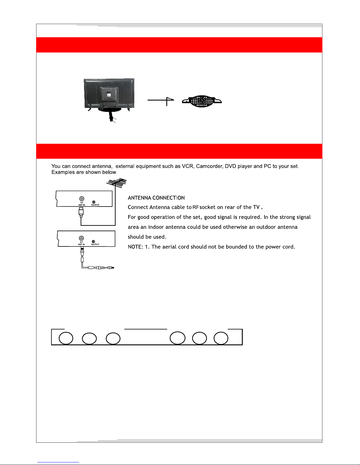
Connect the antenna cable to the socket marked ANT IN on the back cover. For
best reception an outdoor antenna should be used.
Antenna:
Position the set so that no bright light or sunlight falls directly on the screen.Reflections
on the screen affects the picture quality.
Soft and indirect lighting is recommended for comfortable viewing.
Care should be taken not to expose the set to any unnecessary vibration, moisture, dust
or heat.
Adequate ventilation is essential to prevent set failure.Ensure that the set is placed in a
position to allow a free flow of air. Do not cover ventilation opening on the back cover.
Do not place the set in an enclosure or very close to walls.
Avoid excessively warm locations to prevent possible damages to the set.
Place the television on a solid and flat surface.
Location:
1. INTRODUCTION
2
Page 4
No warranty claims are accepted for damage caused due to incorrect handling.
This LED TV Set is designed to receive display video and audio signals and for use as
a PC monitor. Any other use is prohibited.
Despite the high quality of the television, random disturbances or interference may
cause occasional malfunctioning. In this case the correct function of the apparatus can
be restored by switching off the TV through the main On/Off button or removing the
main plug, then switch ON as soon as the LED light disappears.
Cautions.
Note:
For safety, remove the AC plug from the wall outlet before cleaning the set.
Clean the dust on set by wiping the screen and the cabinet with a soft, clean cloth. If the
screen requires additional cleaning, use a clean damp cloth. Do not use liquid cleaners
or aerosol cleaners or liquid containing benzol, petroleum or chemicals.
3
Cleaning:
Do not allow anything to rest upon or roll over the power cord, and do not place the set
where the power cord is subject to damage.
Remove the AC plug from the wall outlet when the TV set is not used for a prolonged
period of time.
In the event of thunder storms or power cuts please remove the main power plug and
aerial plug.
Unplug the set in case of abnormal operation e.g. smoke, odd sound or smells.
Use the main power cord provided for connecting the TV.
Power:
3. TV BRACKET ASSEMBLY
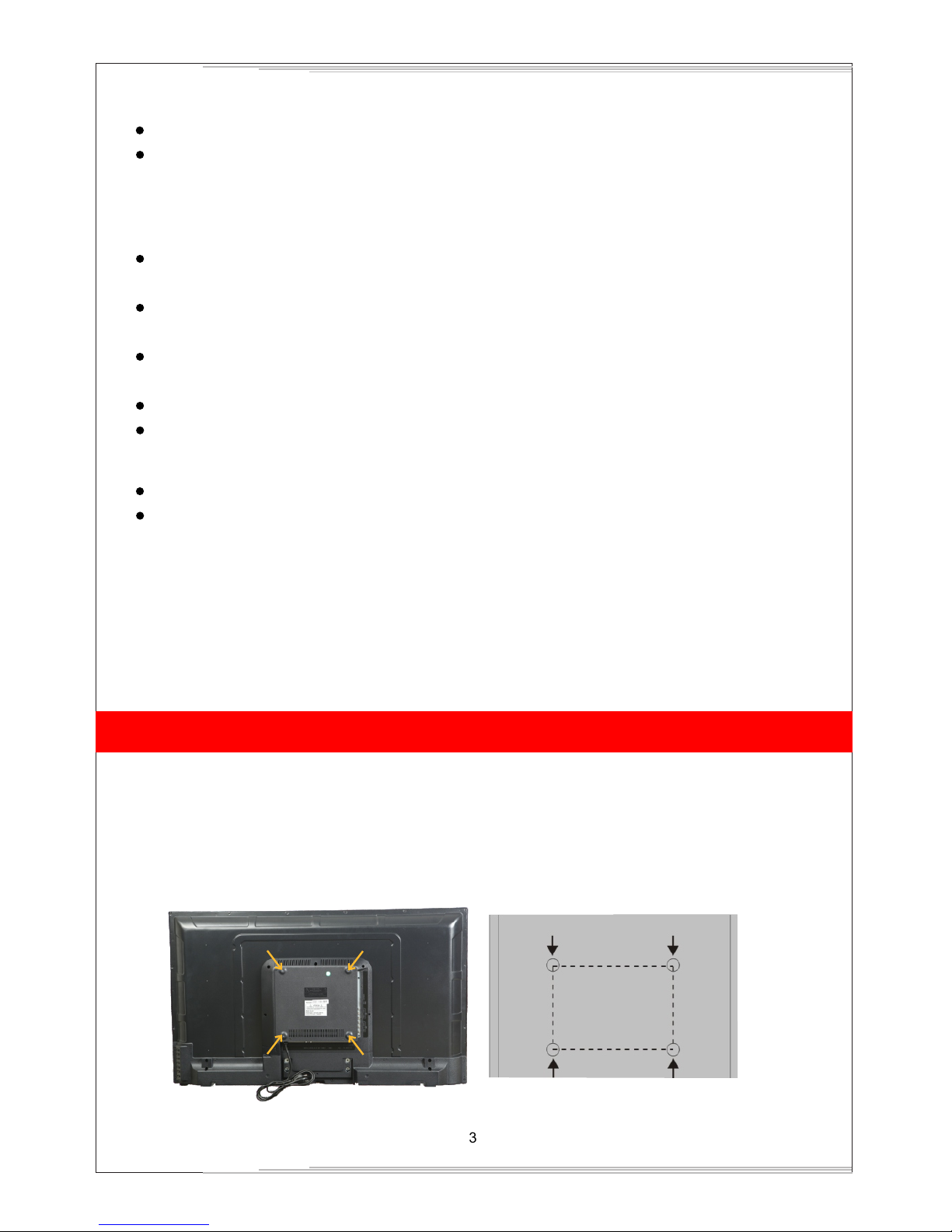
Fixing the LED TV on a wall
1. First, place the LED TV on a table smoothly and place a soft cloth on the table to avoid
scratching the screen.
2. Use a screw driver to take off the screws which are fixed on the bottom stand (Refer to Fig. 1,
direction of the arrows) and take out the bottom stand (please keep the screws and bottom
stand carefully)
Fig1
Fig1a
wall
Page 5
4
3. Make one bracket which can be fixed on the wall according to the size of arrow direction of fig. 2 and fig. 3.
4. Drill four holes on the wall (the size is given only for reference) and fix the TV Wall Mount
bracket on the wall. (This is optional,you may place the tv using a table stand only)
5. Use a screwdriver to lock the screws in the wall mount bracket on the back of the TV,
then hang the TV on the wall.
NOTE:
The bracket fixed on the wall is an optional part.
When you fix wall mount on the TV, there should be no other articles on, around and front
of the TV and please keep a distance from any product hampering articles.
The fixing picture is only for reference.
Please follow the user manual about bracket assembly to fix the TV.
Attach the mounting bracket from the VESA compatible wall mounting kit, provided with the TV.
1.
2.
3.
4.
5.
Fig2
Bracket
Cement bolt
Fig3
wall
3. TV BRACKET ASSEMBLY
(NOTE : For 20" Model the stand screws will be in bottom side.)
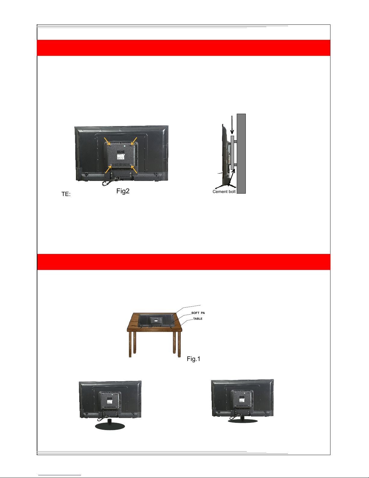
4. DESKTOP TV BRACKET INSTALLATION & ASSEMBLY
Note: Instruction manual for the TV stand assembly.
Step 1: Place the TV carefully on a table covered with a soft pad, this can prevent the LED
panel from being damaged.
Step 2: The Stand-base assembly (fig. 2) has to fit into female hole of the Stand-post properly.
TV
SOFT PAD
TABLE
Fig.1
Fig.2
Page 6
Step 3: Put the "Rotary-CVR plate " to the "Stand-base" in its way properly, and make sure
that the holes of "Stand-post" and "Rotary CVR plate " are aligned rightly. and then
use the screwdriver to fix them together with provided screws.
Step 4: assemble finished.
5
Fig.3
ROTARY-CVR PLATE
SCREW
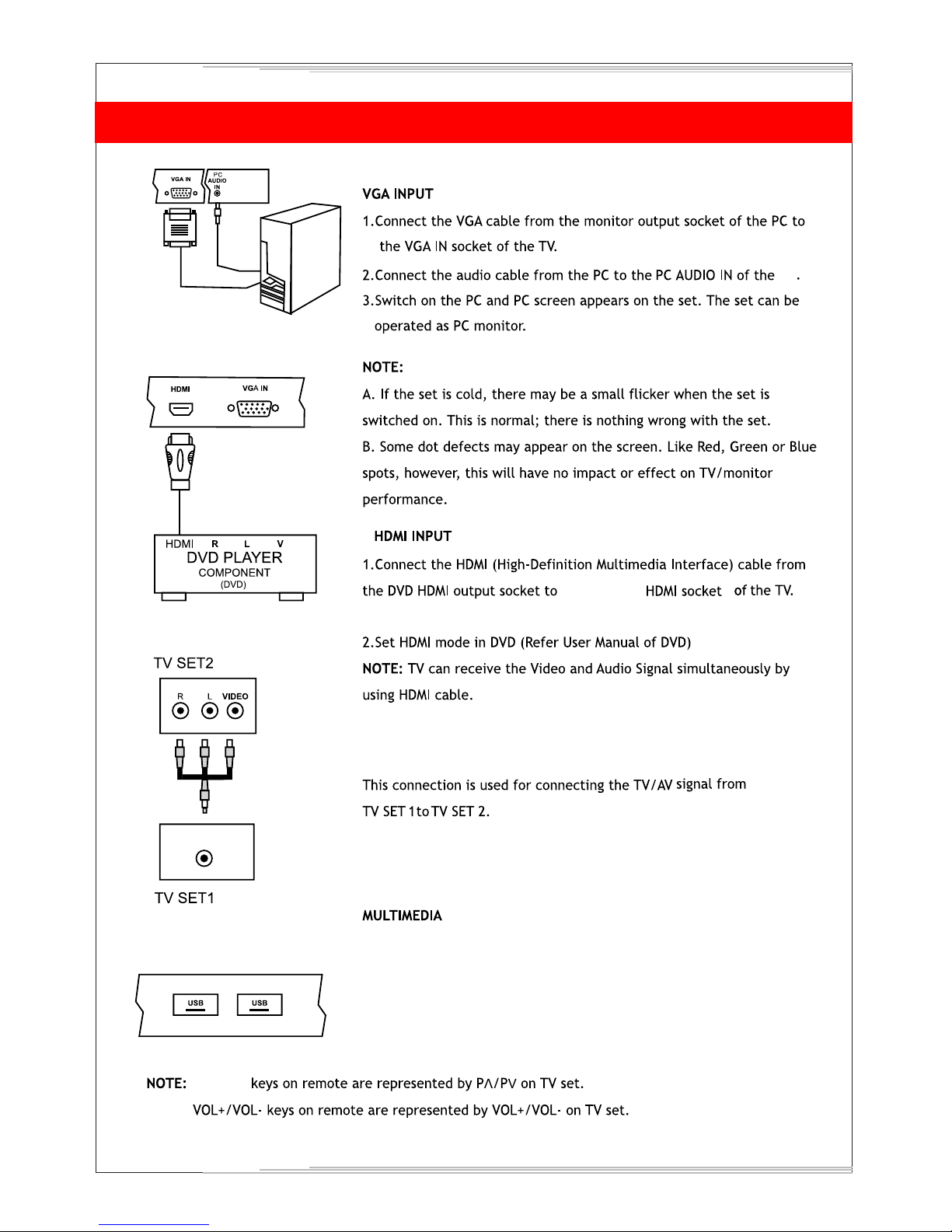
AV INPUT1 / INPUT2
1.Connect the composite outputs (Video, L & R) of VCR/DVD Player to AV INPUT 1 / INPUT2.
2.1 Press the Input button on the remote to select AV1/AV2.
AV Input-1
V
L R
AV Input-2
V
L
R
5. ANTENNA AND EXTERNAL CONNECTION EQUIPMENT
AV
AV
NOTE : Selecting a Source
Remote Control :
Press Input button on the remote control to display' Input source OSD'. Then choose any source by
pressing Up/Down button and Press Enter to select it.
TV Control Panel :
Press Source button and choose any source by pressing Prog+ / - button and Press source
button again to select it.
4. DESKTOP TV BRACKET INSTALLATION & ASSEMBLY
Page 7
5. ANTENNA AND EXTERNAL CONNECTION EQUIPMENT
6
IN
AV output
AV OUTPUT
TV
UP/Down
Connect/Insert standard USB pendrive. Select on source OSD by
pressing Input key, Press Left/ Right key on remote to choose
photo / Music / Movie /text. Similarly TV panel keys Prog +/can be used as Up/Down and Vol+/- for selecting media content
and Press Prog+ to select.
2
either of the 2
s
Page 8
9 7 6 5 4 3
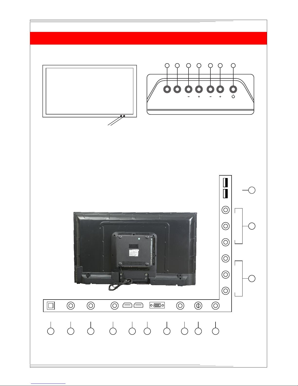
6. NAME AND FUNCTION OF CONTROLS ON SET
A) TV Control Panel Buttons
1.
2.
3.
4.
5.
6.
7.
8.
9.
10.
IR SENSOR
LED INDICATOR
STANDBY
CH+
CHVOL+
VOLMENU
SOURCE (TV/AV)
AC POWER CORD.
11.
12.
13.
14.
15.
16.
17.
18.
19.
20.
21.
22.
AUDIO-L
AUDIO-R
EARPHONE
HDMI
VGA
PC AUDIO
YPbPr
RF
AV OUTPUT
AV INPUT 1
AV INPUT 2
USB
B) CONNECTING YOUR UNIT:-
8
SOURCE MENU VOL PROG
Note:
Above sketches are just representation. Actual TV set may look differ than these sketches.
7
2
AC Power
IN
Earphone
HDMI
VGA
PC AUDIO YPbPr
RF
AV
OUTPUT
10
13
14
15
16 17
18
19
AV INPUT-1
VIDEO L-AUDIO-R
AV INPUT-2
VIDEO L-AUDIO-R
USB
20
21
22
AUDIO-L AUDIO-R
11 12
1
Page 9

7. BATTERY INSTALLATION
1. Remove the battery compartment door.
2. Insert two pieces of 1.5V size UM-4 "AAA" batteries or equivalent with the correct polarity as indicated
by (+) and (-) symbols.
3. Close battery compartment door.
NOTE: Replace batteries when they are exhausted or if the remote control is not to be used for a long
time.
BATTERY PRECAUTIONS:
Incorrect use of batteries can cause electrolyte leakage which will corrode the remote control or cause
the batteries to burst.
Replace both batteries at same time.
Don't Mix batteries type (alkaline with carbon ,zinc etc.)
8
Page 10

9
POWER
FREEZE
S.MODE
P.MODE
FAV
FAV.
FAV+
Turns TV into STANDBY ON/OFF
Select to freeze the scene still on the screen.
Recalls / changes presetted sound settings.
Recalls / changes presetted picture settings.
Press to add or remove your favorite channels under TV menu.
Press to switch your favorite channels under TV menu.
Press to switch your favorite channels under TV menu.
P
P
-Navigates Vertically up/down through the Menu/Sub Menus
-To enter character/numbers in program name parameter
-To navigate channel up/down through valid channels.
-Navigates horizontally right/left through the Menu/sub Menus.
-To enter in Menu/Sub Menus and to adjust Vol +/-
-To navigate the letter in program name parameter
-To select the time
-Increase/decrease the value of selected items and set the parameter On/Off
<>
ENTER
-To enter in sub menu.
-Enter to edit program name parameter.
Press to exit the OSD menu.
To select menu OSD window and return to upper menu.
Input source selection.
Select to increase or decrease volume.
Select to increase or decrease volume for power audio.
EXIT
MENU
INPUT
VOL +/PA +/-
This key provides different power saving modes. The current mode is displayed with
ecovision symbol on the screen. In audio only mode display is off and only audio is on. Press
any key to exit audio only mode. Note : VOL+/-, PA +/- and Mute can function even as
panel is off.
Turns sound OFF or ON
ECO
MUTE
Figures 0-9 are used to directly input channel number.
Press this key to enter the program number for different digit eg. -/--/---
1 2
3
4
5
6
7 8
9
0
-/--
Q.VIEW
Press this key to toggle between the current and the previous program you were watching.
-Press this key to save channels when manual tuning or to delete channel when editing TV
program in Program edit function.
-To set sleep timer except when in Program Edit Menu or USB mode
-To delete item selected in USB mode.
-Press this key to display sub title list
-Press this key to rename channels in program edit function
-In USB Mode, Info copy from USB 1 to USB 2 and Vicen versa
(only for 80cm &102cm LED TV Model)
NAMES AND FUNCTION OF CONTROLS ON REMOTE
Sub Title
Sleep
Delete
Copy
Page 11

NAMES AND FUNCTION OF CONTROLS ON REMOTE
-Press this key to switch aspect ratio
-Press this key to skip channel in program edit function
Press this key to STOP in USB mode
Press this key to PLAY/PAUSE in USB mode
Press this key to fast reverse in USB mode
Press this key to fast forward in USB mode
Press this key to select play time position
When playing the Photo or Video or MP3 or Text, if you select ROOT key it wil
stop playing and return to the current list in USB mode.
Press this key to play the previous track.
Press this key to play the next track.
-Press this key to switch On/Off Internal speaker used in TV set.
-Press this key to swap channel in program edit function
Speaker
Aspect
>>
>>
GOTO
ROOT
>>
>>
10
9. PICTURE MENU
Picture Mode
Contrast /
Brightness / Color/
Sharpness / Tint
This function is used to select the preset picture setting
(Dynamic/Standard/Mild/User)
These settings are used to adjust the Contrast (0-100), Brightness (0-
100),Color (0-100), Sharpness (0-100) and Tint (0-100) Changes in
these settings should be done for fine adjustments of the picture.
Note: Tint is enabled for NTSC channels only.
Color Temperature
Use this option to select and change color temperature
(Normal/Warm/Cool/User).
Upon selecting user mode can be adjusted as per choice.
Red/Green/Blue settings and adjust color temperature of preference.
Aspect Ratio
You can adjust Aspect Ratio to have picture setting of your choice
(16:9/Panorama/Auto/4:3/14:9/Zoom/Cinema Zoom).
You can adjust Black Level Off/Dark/Darker/Darkest to get the
desired screen depth.
Black Tone
Adjust the screen contrast Off/Low/Medium/High
Adjust skin tone to your choice.
You can adjust Low/Middle/High/Auto/Off to reduce the noise by
applying noise reduction filters to video data
Dynamic Contrast
Flesh Tone
Noise Reduction
PICTURE
Dynamic Backlight
The backlight value can be varied (1-10). This function is used to
adjust level of panel
Ecovision
TV is in Normal state when this is off. To save power consumed by TV
select power saving modes Low/Mid/High/Audio Only. In Audio Mode,
only audio is on and picture is off. Volume, Power Audio and Mute
keys will work in Audio Mode Only. Press any key to exit Audio Mode Only.
Page 12

11
Speaker
When set to On audio can be heard from internal TV speakers. When
set to Off internal TV speakers will close sound.
10. SOUND MENU
Sound Mode
Balance
Auto Volume
Surround Sound
EQ
SOUND
This function is used to select the preset sound modes
(Standard /Music /Movie/ Sports/ User)
User can select the left/right speaker intensity by changing balance
(-50 / +50)
When set to On, it will level out the sound being heard when sudden
changes in volume occur during commercial breaks or channel
changes.
Select Surround Sound On or Off to have spatial effect
Equilizer 120Hz, 500Hz, 1.5kHz, 5KHz and 10KHz can be adjusted by
user to get best sound setting of the choice.
11. TIMER MENU
TIME
Clock
Off Time
On Time
Sleep Timer
Auto Sleep
SOUND
Power Audio
Volume
You can connect any Home Theatre speakers to AV Output. Now TV
remote Power Audio Volume (PA +/-) can control sound of your music
system and also mute the sound.
Display the On Time and Date. Press Enter key to adjust Date,Month,
Year, Hour and Minute.
Adjust what time TV should enter standby mode.
Adjust what time TV should switch on from standby mode.
Select the time in minutes (10min to 240min) in which you want
the TV to shut off
If keep it ON,the TV will switch off after 10 min when no signal is
available.
Page 13

TV Manual Tuning
Sound System: Select the sound system (DK/BG/MN/I)
Search: Press < to search down from the current frequency and press >
to search up.
Fine-Tune: Fine tunning the channel at which either picture or sound is
not clear even after Auto Searching
Storage To: Select the channel tuned to copy to other program number
CHANNEL
Programme Edit
User can edit the programs by Swap, Skip, Rename operation.
1. To Swap, Navigate to channel to be swapped (selected bar appears
on it) press yellow key on remote, navigate to another channel press
OK. Now press yellow key again on remote then these two channels are
will be swapped.
2. To Skip, Navigate to channel to be skipped (selected bar appears on
it ) press blue key on the remote. Channel is skipped. Repeat the
process to cancel skip.
3. To Delete, Navigate to channel to be deleted (selected bar appears
on it ) press red key on the remote. Channel is deleted.
4. To Rename, Navigate to channel to be rename (selected bar appears
on it ) press green key on remote. Now you navigate keys up and down
to enter word and move front and back to shift.
Favorite
Favorite channels can be selected by using the FAV key on the remote.
Navigate to a channel to be included in favorite list (selected bar
appears on it ) press FAV key. Heart sign appears with channel selected.
To Cancel repeat the operation again. After you select all favorite
channels you can use FAV- and FAV+ keys to watch all selected favorite
channels one by one.
Save : Save the channel number selected.
12. OPTION MENU
OSD Language
Adjust the language. as per the current software only English language can be set.
Blue Screen
Select On to get Blue Screen when no signal is available on TV set.
Select any one of the four games as per your choice
Games
13. CHANNEL MENU
Auto Scan
CHANNEL
Select this function TV will start auto tuning for all available channels.
If you want to stop auto searching press MENU or EXIT and press, < to
confirm, > to cancel.
Current CH: Display the program number of the current channel.
Color System: Select the color system PAL/SECAM/NTSC
12
OSD Duration
Adjust the appearance duration of TV display for 15 sec., 30 sec.,
60 sec. as desired by customer.
OPTION
Select to return TV back to all default settings.
Reset Default
Page 14

14. HOTEL MODE
HOTEL
SETTING
Hotel Lock
Lock Channel
Set Source
Channel Number
Picture Lock
Key Lock
Max Volume
Source Lock
Clear Lock
To enter Hotel Setting Mode dial MENU+1194 from remote control.
Make this switch ON to activate Hotel Lock options. When this switch is
OFF hotel lock options will not operate. Use Navigation keys to ON/OFF
this function.
Select this option On, Channel Menu will not appear in main menu so
channel tuning is locked.
Select the power on source. After the TV switeches ON the power on source
will be same as specified here.
Select the power on channel (1-200) , after the TV mains On the power
on channel will be same as specified here.
Select this option On, Picture Menu will not appear in main menu so
picture settings are locked
Select this option On, all the panel keys will be locked and not work.
The main volume is limited by setting MAX
Select this option to lock all the source/input in TV that you don't
want others to use, Only TV source cannot be locked.
Select this option to reset all Hotel Setting to default.
Note:
1.
2.
3.
4.
5.
Timer will get reset if main power On/Off
Use Left/Right keys on the remote to change Option and Up/Down keys to navigate.
Press Enter key on remote to enter into sub menus.
Press CH+/- key on TV panel to navigate.
Press Vol +/- keys to change option..
13
15. MEDIA
"NO DEVICE" icon means TV has not detected USB memory.
Press
to select Photo/Music/Movie/Text icon and ENTER to enter the USB memory.
For details :
Photo, see page "16"
Music, see page "17"
Movie, see page"18"
Text, see page "19"
Photo
Menu
Exit
Select
Move
No Device
Page 15

16. MEDIA PHOTO
Photo
Select one and press to view and it will display all the pictures in the folder automatically.
Press ENTER to display the following menu, then you can press to select them.
Rotate counter clockwise.
Rotate clockwise.
Zoom the picture in.
Zoom the picture out.
Zoom out the picture first.
Highlight the icon and press ok, then press & to move the picture.
Press to display the information of the current picture (Resolution/Size/Date/Time)
i
info
90
Rotate
90
Rotate
Zoom In
+
Zoom Out
+
Move View
Press to play or pause
Press to view the previous picture.
Press to view the next picture.
Press to stop and back to the previous folder.
Press to play all the pictures repeadetly in the current folder.
Press OK to select the repeat mode: Repeat One/ALL/None
Press to play or stop the background music.
Press to view the list of pictures.
Play
Prev.
Next
Stop
RepeatAll
Music
Playlist
14
Page 16

17. MEDIA MUSIC
Music
Press to play the selected music file.
Press to play or pause
Press to fast backward
Press to fast forward
Press to play the previous song.
Press to play the next song
Press to stop and back to the folder interface.
Press to play all the songs repeatly in the current folder
Press OK to select the repeat mode: Repeat One/ALL/None
Press to go the point you want to play.
Play
FB
FF
Prav.
Next
Stop
Repea..
AB
15
Press Mute to mute the Audio
Press to view the list of Music.
Goto Time
Mute
Playlist
Pause
FB
FF
Prav.
Next
Stop
Repea..
AB
Goto Time
Pause
Album Fakeera
Titles songs.pk
Artist: Abhijeet Sawant
Bit Rate: 120k Sampling: 48k
Year: 2007 Size: 5370 kbytes
1
1
Janam Janam.mp3
Janam Janam.mp3
00:00:08 / 00:05:43
Janam Janam.mp3
Page 17

Aspect..
18. MEDIA MOVIE
Movie
Press to play the selected movie file.
Press to play or pause.
Press to play backward faster.
Press to play forward faster.
Press to play the previous movie.
Press to play the next movie.
Press to stop and back to the folder interface.
Press to play all the movies repeatly in the current folder.
Press OK to select the repeat mode: Repeat One/ALL/None
Play
FB
FF
Plev.
Next
Stop
Repea..
AB
16
Set A-B to play repeatly.
Press once to set A, and press again to set B, then press the third time to cancel.
Press to view the list of movie.
Press to display the information of the current movie.
Press to play slower.
Press to play the movie step by step.(frame by frame.)
Press to go to the point you want to play.
Press to Zoom in
Press to Zoom out
i
info
Set A
AB
Playlist
Slow Forward
Step For...
Goto Time
Zoom In
+
Zoom Out
+
Press to change aspect ratio
Movie
view
Press Enter, then press Up/Down & Left/Right to move.
Pause
FB
FF
Prav.
Next
Stop
Repea..
AB
Goto Time
Pause
-
-
Page 18

Prev.
19. MEDIA TEXT
Text
Note: Only The*, txt file can be detected and read only.
Press to display the selected text file.
Select previous page.
Select next page.
Press to go to the previous text file.
Press to go to the next text file.
Press to stop and back to the folder interface.
Press to play or stop the background music.
Press to view the list of the text files.
Press to display the information of the current files.
Playlist
Next Page
Prev. Page
i
info
Stop
Next
Music
17
Pause
Microsoft community affiars provides training and tool that creat theb social
and economic opportunities that can transform communities and help people
realize their potential. Through our programs and our partnerships, Microsoft
supports numorous projects and organizations around the world working to expand
opportunities, and help improve digital inclusion, through technology access and
training.
FB
Janam Janam.mp3
FF
Prav.
Next
Stop
Pause
-
-
Music
Playlist
Page 19

20. USB to USB Copy (Only for 80cm 102cm LED TV)
18
SPECIAL FEATURES : (Optional)
1. USB to USB Copy Function : (From USB1 to USB2 & USB2 to USB1)
Copy files from USB1 to another USB2 by Remote Control.
Insert USB1 in port 1 of which files to copy in USB2 Port 2.
Now Select USB1 by remote & select files to copy.
Press Green Colour Sub Title key by remote, copy function will start
as per the following display on LED TV screen.
Copy File : File 1
Copy File Complete!!
Copy File : File 1
From : USB1/
To : USB2/
46%
USB-1
TO
USB-2
COPY
USB-2
TO
USB-1
COPY
USB-1
USB-2
Page 20

21. USB FORMAT
19
USB 1 & 2 (Multimedia File Formats)
File Ext: Remarks Video Codec Frame Rate Bit Rate
dat , mpg.
mpeg
ts, trp, tp
vob
mp4
rm, rmvb
mkv
DivX , avi
asf
MPG, MPEG
MPEG2 -TS
H264-TS
MPEG2 -PS
AVI, MP4
RMVB, RM
MKV
AVI (1.0, 2.0)
DMF0, 1, 2
ASF
(Revision
01.20.03)
Mpeg1,2
MPEG2, H.264
MPEG2
MPEG4
DivX 3.11, DivX 4.12, DivX
5.x, DivX 6, Xvid 1.00,
Xvid 1.01, Xvid 1.02, Xvid
1.03, Xvid 1.10-beta1/2
H.264
rm code RV8, RV9, RV10
H.264, MPEG1,2,4
MPEG2, MPEG4
DivX 3.11, DivX 4.Divx 5, DivX
6, Xvid 1.00,
Xvid 1.01, Xvid 1.02, Xvid
1.03, Xvid 1.10-beta1/2
H.264
VC1
1920x1080@
30P
1920x1080 @
30P
1920x1080 @
30P
1920x1080 @
30P
1280x720 @
30P
1920x1080 @
30P
1920x1080 @
30P
1920x1080 @
30P
20Mbit/sec
20Mbit/sec
20Mbit/sec
20Mbit/sec
10Mbit/sec
20Mbit/sec
20Mbit/sec
20Mbit/sec
Audio multimedia file formats
Audio Codec File Extension Bit Rate
MPEG1 Layer2
MPEG1 Layer3
MP3
MP3
32Kbps ~ 448Kbps(Bit rate)
32KHz ~ 48KHz(Sampling rate)
32Kbps ~ 320Kbps(Bit rate)
32KHz ~ 48KHz(Sampling rate)
Page 21

22. USB FORMAT
20
AC3 (Need License)
EAC3 (Need License)
AAC, HEAAC
WMA
LPCM
IMA-ADPCM/MS-ADPCM
LBR
N/A (work with video files only)
N/A (work with video files only)
M4A/AAC
WMA/ASF
N/A (work with video files only)
N/A (work with video files only)
N/A (work with video files only)
32Kbps ~ 640Kbps(Bit rate), 32KHz,
44.1KHz, 48KHz (Sampling rate)
32Kbps ~ 64Mbps
32KHz, 44.1KHz, 48KHz(Sampling
rate)
24Kbps ~ 384Kbps (Bit rate)
8KHz ~ 48KHz (Sampling rate)
Bitrate: 128bps ~ 320Kbps
Sampling Rate: 8KHz ~ 48Khz
Bitrate: 64Kbps ~ 1.5Mbps
Sampling Rate: 8KHz ~ 48Khz
Bitrate: 384Kbps
Sampling Rate: 8KHz ~ 48Khz
Bitrate: 6Kbps ~ 96Kbps
Sampling Rate: 8KHz ~ 48Khz
Digital multi media picture file formats
Image Phote
Resolution
Pluto
suggest)
T2 &
(M-Star
Resolution T3/T4
(Mstar suggest)
Required DRAM size
by T3/T4 (Mbytes)
JPEG
PNG
BMP
Base-line
Progressive
Non-interlace
Interlace
8192x8192
1024x768
9000x6000
1200x768
9000x6000
15360x8640
1024x768
9600x6400
1200x800
9600x6400
3. 96
6. 00
3. 66
3. 66
3. 66
Remark :
some of video files and audio files need customer supply license can be open such as AC3 /DIVX
Note:
The multimedia features/functions may vary from file to file depending on relative information present in the file.
If can't detect the connected device, it would be caused by connected device driver not by TV failure
USB port of device provides 5V & max current 500mA. Because port specs adopted by certain storage device is different form that
of standard USB, so it may affect the correct identifications.
The reading speed will be variable due to different connected devices & different storage capacities.
Manufacturer of this LED TV is not responsible if USB device is not supported, nor is it responsible for damage or loss of data.
Due to difference of equipment & storage capacity the time need to read information also different. The speed of reading
information may slow down temporarily, note that this is not break down of the unit.
When system is executing your last operation, please do not press function keys continually, otherwise it will affect processing
speed of system.
1.
2.
3.
4.
5.
6.
7.
Page 22

23. TECHNICAL SPECIFICATIONS
NOTE:
1.2.Design and specifications are subject to change without prior notice.
Stand assembly is optional and is not a part of this unit. For more
details contact service provider.
21
59cm LED
1366 x 768
250 nits
5mS
O
178 (H) O/ 178 (V)
PAL/SECAM, BG/DK NTSC
(3.58/4.43) in playback only.
VHF 2-12
UHF 21-69
CATV (X-Z+2, S1-S41)
AC 90~270V, 50/60Hz
75 Ohms unbalanced
45W
8W x 2
Panel Type
Display Resolution
Brightness
Response Time
Viewing Angle
Receiving Systems
Channel Coverage
Power Supply
Antenna Input Impedence
Power Consumption (MAX)
Audio Output (RMS)
Accessories
80cm LED
1366 x 768
250 nits
8mS
O O
178 (H) / 178 (V)
PAL/SECAM, BG/DK NTSC
(3.58/4.43) in playback only.
VHF 2-12
UHF 21-69
CATV (X-Z+2, S1-S41)
AC 100~250V, 50/60Hz
75 Ohms unbalanced
57W
10W x 2
Remote Handset, User
Guide Book
102cm LED
1920 x 1080
300 nits
8mS
O O
178 (H) / 178 (V)
PAL/SECAM, BG/DK NTSC
(3.58/4.43) in playback only.
VHF 2-12
UHF 21-69
CATV (X-Z+2, S1-S41)
AC 100~250V, 50/60Hz
75 Ohms unbalanced
85W
10W x 2
Remote Handset, User
Guide Book
Remote Handset, User
Guide Book
Page 23

24. TROUBLE SHOOTING
Before you call the service person, check the following points.
PROBLEM
No picture on screen and no sound
from speakers.
No picture from AV terminal
Picture is displayed but no sound from
the speakers.
Picture is too light.
Picture is too dark.
Remote control does not work
The picture is not sharp. The picture
moves. Picture is snowy and
noisy sound.
The Multiple image and normal sound
The picture is spotted or interference
on picture and noisy sound.
There are stripes on the screen or color
fade on interference
Picture with no color but normal sound
Picture is scrambled and with normal
or weak sound
Incorrect position of picture in PC mode
Vertical bars or stripes on background
in PC mode
Horizontal noise in PC mode
CHECK ITEM
> Insert the AC power cord plug securely in AC power socket.
> Make sure the set is not in stand by mode.
> Turn on the power button on the set.
> Check the brightness setting of the set
> Make sure a cable with no video input signal is connected to the AV
INPUT terminal.
> Check the volume settings.
> Make sure the sound is not muted.
> Make sure the speaker is not turned off in sound menu.
> Make sure that sound system is correct.
> Make sure COLOR and CONTRAST settings are proper.
> Make sure BRIGHTNESS setting is not set too low. Check the BRIGHTNESS setting.
> Change the batteries.
> Make sure the infrared transmitter window is not receiving strong light such as light
from fluorescent lamps.
> The reception may be weak try another channel.
> The state broadcast may also be bad.
> Make sure that the antenna is facing the right direction.
> Make sure the outside antenna is not disconnected.
> Try different channels if ok probably it is station problem.
> Make sure the antenna is facing the right direction.
> There may be reflected electric waves.
> There may be interference form automobiles, trains, high voltage lines, neon lights etc.
> There may be interference between the antenna cable and the power cable.
Try positioning them further apart.
> Check color setting or the set and check color system.
> Check if station is broadcasting color picture.
> Retune Channels
> Auto adjust H/V position.
> Manually trail to adjust HV position.
> Auto adjust, try to adjust clock manually.
> Auto adjust or adjust phase and clock.
22
> Is the unit receiving interference from other devices? Transmission antennas of radio
broadcasting stations and noisy sound and transmission antennas of cellular phone.
> Place the unit as far as possible from devices that may cause possible interferences
Page 24

The Kodak trademark, trade dress and logo are used under
License from Kodak.
c
SPPL 2016.
Super Plastronics Private Limited
B-29, 30 & 31 Sector - 81 Phase 2 Noida
201305
+919311119721
www.kodaktv.in
 Loading...