

Page 1
Warranty
To receive after-Sale service, have the following ready
when you contact our branches
1. Name of the product
2. Model number of the product
3. The area of problem
4. Phone number and address at
which you can be contacted.
Warranty Card
PRODUCT
MODEL
DATE PURCHASED
WARRANTY PERIOD
AGENCY ADDRESS
KOCOM Warranties the original purchaser of this product
as follows.
1) This product is produced under strict quality control and inspection procedures.
2) If this product breaks down during proper use as a result of product defect, KOCOM
will repair it within one year from date of purchase free of charge.
3) The following cases will be subject to charge, even during warranty period:
a. Breakdown during transport, or through careless treatment, by consumer.
b. Breakdown cause by unauthorized repair, or system modification.
c. Breakdown caused by natural disaster or power disorder.
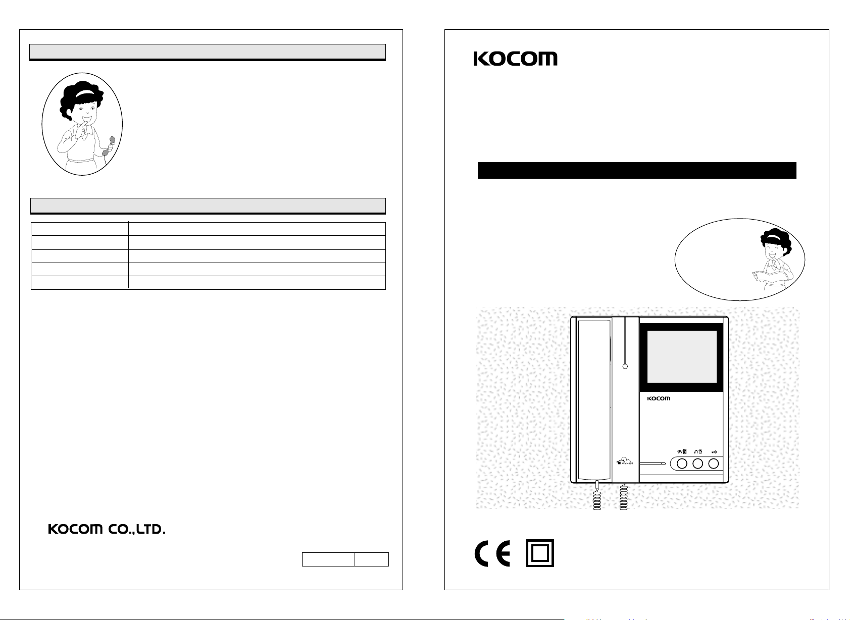
Video Door Phone
for Apartment Unit
KVM-520 Users Manual for Operation and Installation
Communication with and monitoring by front door camera
Interactive call and communication between house and guardroom
Inner line call and communication within the house
Communication with lobby phone and door open function
Thank you very much
for purchasing KOCOM
video doorphone.
please read this manual
thoroughly to ensure
correct usage, before
operating
This manual is based on the date as shown in the right and specifications
are subject to change without notice for quality improvement.
KVM-520 04.07
Page 2
Cautions for Safety
For safe use, please stick to the following cautions.
Warnings
Warnings for disposal
�
Do not throw used-up battery into fire places, which may cause fire and explosion.
�Read this cautions carefully and keep it within easy reach of you.
�For right installation, read this cautions thoroughly. Please install the product according to its specifications.
�This Cautions for Safety may include items that are not contained in specifications of the product that consumer
purchases.
�Reading this cautions, use the product in a right manner. For further information, please contact our A/S center.
About Symbol
A variety of symbols are used in this Cautions for Safety and your products to guide you to use products in a right
and safe manner and to prevent possible risks for users and other persons and damages to their property. The meaning
of each symbol is as follows. After fully aware of meaning of each symbol, read the following cautions.
This symbol means that wrong handling or ignorance of matters that this symbol indicates
Warnings
may cause serious injury or even death of user.
This symbol means that wrong handling or ignorance of matters that this symbol indicates
may cause serious injury or property damage of user.
Cautions
This symbol means the matter that user should not do at nay event.
This symbol means that user should follow the instructions.
Symbols on Drawing
Cautions
Cautions for installation
�
The relevant law obliges users to have a qualified electrician carry out wiring work for power supply. Work by disqualified
persons may cause fire and electric shock.
Wiring work for communication cables needs techniques and experiences. For this type of wiring work, please consult to your
�
local sales agent.
According to the standard for electric work and other relevant regulations, install communication cables at the place away
�
from power cables. The failure to install cables separately may cause fire, electric shock and communication troubles.
Do not install the product on rolling table or sloping place.
�
Dropping or falling may cause damage on your product.
In installation, avoid the place exposed to tremor or shocks, which may cause damages on your product.
�
Even if your product is waterproof, do not install it slanted place of water leakage, which may cause a short circuit.
�
For the product of wall-mounting type with fixing pegs, keep it safely.
�
Fixing pegs may cause injury of user.
�
Install the product of wall-mounting type carefully not to drop from the wall. Dropping due to earthquake or tremors may
cause injury of user.
When installing the product on the wall, consider the thickness and material of the wall.
�
Dropping in use may cause injury of user.
Cautions for Use
Do not put heavy thing on the product. Dropping or falling due to heavy things on it may cause injury of user.
�
This symbol means that contents (high voltage, electric shock, warnings, etc.) to which user
should pay attention are included.
This symbols means that a certain action is not permitted. Specific points not permitted are
depicted around this symbol (for example, in the left drawing, disassembly is not permitted.).
This symbol means instructions or is used to force user to do a certain action. Specific
instructions are depicted on the drawing
(for example, the left drawing instructs user to detach power plug from an outlet).
Cautions for Repairs and Maintenance
Clean the dust inside the product regularly. Failure to clean the dust for long time may cause fire. For inspection and cleaning
�
of the inside of product, please contact your local sales agent.
When putting your hands into the inside of equipment, be sure that plug is already detached form an outlet or circuit-breaker is
�
turned off.
Be careful not to expose the product to benzene, thinner or hot water.
�
Do not expose detergent directly to the product in a way of spaying, etc.
�
Moving equipment, be sure that the plug is detached from an outlet.
�
For equipment whose cables are connected to terminals, please contact your local sales agent or qualified electrician.
�
When replacing old fuse with new one, do not directly touch it with bare hands.
�
Use insulated tools or contact A/S center.
Page 3
Warnings
Warnings
Cautions for Use
�Do not install the product at bathroom or at the place near a washing machine, or at other humid places. It may cause fire or
electric shock.
�Do not install the product at the place near a dresser, humidifier or heater. Also avoid the place exposed to spark, heat or
humidity. All of them may cause fire and electric shock.
�Do not install the product at the place exposed to dust, metals and harmful gas such as hydrogen sulfide gas, all of which
may cause fire and electric shock.
�Do not install the product at the place exposed to water and chemicals. This may cause fire and electric shock.
� Do not scratch, break or arbitrarily process power cable, which may cause fire and electric shock. Putting a heavy thing on a
cable, heating it or pulling it may cause impairment on it.
�Do not place power cable at the place near heating equipment. It may cause damage of cable's clothing material, which
result in fire ad electric shock. When detaching plug from an outlet, do not pull power cable.
�Damages on power cable may cause fire and electric shock. When detaching plug from an outlet, please hold the plug
tightly.
�Do not detach plug from an outlet with wet hand. I may cause electric shock.
�When using the existing wiring, be sure of the suitability of it to the product and install the product. Failure to this caution
may cause fire.
�When moving equipment, be sure that plug is detached from an outlet and communication cable is disconnected. Damage
on cables may cause fire.
�Voltage other than prescribed rated voltage is not permitted, which cause fire and electric shock.
�Do not use power terminal of product's main body in other equipment than prescribed ones. It may cause fire and short-
circuit.
�In wiring work, use the designated wiring materials.
Wiring work using other materials than designated ones may cause fire.
� The equipment without waterproof marking shall not be installed at the place water leaks. It may cause electric shock and
short circuit.
�When working, be sure that power is disconnected. Failure to disconnect power may cause electric shock.
� Be sure that the power cable is connected and earths according to designated method. Failure to connection and earth may
cause fire.
�Do not connect power to other terminals than designated ones.
�It may cause fire and electric shock.
� When building a system with the product, do not connect the product other equipment than designated one. It may cause
fire.
�When installing A/C switch, do work after removing the substance that may cause short circuit or electric shock.
�Before installing or providing A/S service, be sure that the power is disconnected.
Cautions for Use
�This product is only for home. Do not the product for industrial or military use.
�Do not handle the equipment with wet hand, which may cause electric shock.
�Do not place wet or metallic materials on equipment. Water leakage or intrusion of metallic materials may cause fire and
electric shock.
�Do not block the ventilating opening of equipment or put alien substances into it, which may cause fire and electric shock.
�Do not use battery that is not designated or mix new battery with old ones. Insert batteries to fit their polarity. Explosion or
leakage of battery may cause fire and injury of user.
�When visitor's image or voice is not displayed on screen or not sounded from speaker, please check his/her identity before
opening the door and contact our A/S center.
�Do not use equipment when lighting is expected or strokes. It may cause fire and electric shock.
�Do not open rear cover, cabinet and cover of equipment. It may cause electric shock.
�Do not modify power cable or pull it with excessive strength, which may cause fire and electric shock.
�Do not modify equipment. It may cause fire and electric shock.
�Call signal may cause damage on user's hearing ability.
Cautions for Abnormality
�When power cable is broken (exposure of core or short-circuit), do not fail to replace broken cable with new one. Failure to
replace broken power cable may cause fire and electric shock.
�When detecting any abnormalities in equipment (communication is not available, images do not be displayed on screen, calling
is not available, or abnormal sound is heard), immediately detach plug from an outlet, or turn off circuit breaker or detach
batteries from equipment (in case that equipment has no plug) before requesting repairs to sales agent or A/S center. Keeping
connection to power supply may cause fire and electric shock.
�When alien substances go into equipment, immediately detach plug from an outlet, or turn off circuit breaker or detach batteries
from equipment (in case that equipment has no plug) before requesting repair to sales agent or A/S center.
�In the case of smoke or smell of unknown origin from equipment, keeping use it may cause fire and electric shock. Detach
plug from an outlet, or turn off circuit breaker or detach batteries from equipment (in case that equipment has no plug) and be
sure to check no more smoke or smell from equipment before requesting repair to sales agent or A/S center. Since personal
repairing work by user may serious accidents. In any case, do not repair equipment with your own hand.
�When dropping equipment or breaking its cabinet, detach plug from an outlet, or turn off circuit breaker or detach batteries
from equipment (in case that equipment has no plug) before requesting repair to sales agent or A/S center. Keeping use
equipment may cause fire and electric shock.
�Avoid direct exposure to sunlight and store equipment at the place free from dust and high temperature as you can. High
temperature of equipment may cause fire and electric shock.
Page 4
Safety Instructions, Warnings, and Cautions of Each System
- This equipment is electronically precision equipment, so do not arbitrarily disassemble it.
- In installation of the product, do not fail to follow the specifications (specifications offered by KOCOM).
- Do not touch the product with alien materials (for example, sticker, magnet, opener, metal chopstick, etc.)
or insert them into the product (it may cause reduction of the product's durability and harmful results to user as well).
- In the rainy season, water is likely to penetrate into the product along the wiring. Thus, U-type finishing is recommended
as a desirable method of end part finishing.
System for Multi-unit Housing
- In installation, be careful that other wiring or metallic substances should not contact to the system for multi-unit housing.
- In installation, be careful that alien substances should not go into the system.
- Before installation, be fully aware of wiring specifications of each model.
- In installation, be sure that the length and dimension of wiring meet the requirement prescribed in installation manual.
- Excessive strength and external shock may cause mechanical breakdowns of equipment.
- Do not arbitrarily open the case of the product
(When user opens the case arbitrarily, KOCOM may reject to provide A/S service).
Lobby Phone: KLP-(100, 104, 108, 112), KLP-(P100, P104, P108, P112), KDP-(100, 104, 108,112)
- A stroke of lighting or strong shock may give fatal and adverse effects on system. Thus, do not fail to ground the system.
- For registration of household password, please refer to user manual of the concerned product (it is applied to ten-key lobby phone products
[KLP-100, KLP-P100 and KDP-100]).
Image Splitter: KSV-104P
- An image splitter can support up to four households.
- In the case of over four householders, additional image splitters are needed.
Image Amplifier: KHU-102P
- In installation, follow the specification for image in/output.
V ideo Phone
- In assembling the product, be careful that wall-mounting pegs should not contact with wirings.
- In connection of cables, strip its insulation off as much as necessary (Excessive stripping off its insulation may cause short circuit).
- Be careful that signal cables should not be wired with A/C wiring (it may cause poor display quality).
- Do not drop handset (its damage or short-circuit due to drop may make communication impossible).
- When connecting wires to terminals, use standard screwdriver (otherwise, screws may loosen, which will result in disconnection of wiring).
- Do not clean CRT screen with wet towel or cloth. When water penetrates into the product, it may cause short-circuit.
Do not fail to clean it with dry towel or soft cloth.
- Do not install camera at the place where water penetrates or leaks. Penetration or leakage of water may cause electric shock or short circuit.
Home Auto: KHV-444/454/446/456
- Do not insert any metallic materials into the inside of fuse cover. It may cause electric shock.
- Do not close ear to speaker. Abrupt call or signal may give harmful effects on user's hearing.
- After turning power on and off, check again that input contents are saved correctly. Otherwise, data may be missed when auto-signal mode operates.
- Use a standard detector. Non-standardized detectors are likely to cause fire due to excessive voltage or current.
- Please install motion detector at a place easily detect the motions of subjects. When detector is installed at a wrong place or obstacles block the front
side of detector, it cannot work well.
- When setting night guard mode, be sure that detector should be connected well.
- Sufficiently charge the battery of wireless handset before using it. Be careful that children should not throw battery. Be sure to close battery cover
(When children throw or disassemble battery, it may cause serious accidents).
- Be careful that the polarity of the product matches to that of guardroom communication cable. When polarity is reversed, it may cause abnormal
operations of the product or apartment system as a whole.
4-Line Related Products: KVM-930, 931, 960, IP-203APB, AM-10KP, KCV-344/354
- In wiring work, be careful that wirings should keep away from the wall-mounting pegs or other furniture at regular interval. Contact of wiring with
wall-mounting pegs, etc. may cause short-circuit, electric shock and fire (it is applied to all products with wall-mounting pegs).
- Use the prescribed standard wirings. Non-standardized wirings may give adverse effects on operation of product
(it is applied to both video phone and CCTV).
CCTV Camera
- Do not install at noisy places.
- Do not install at the place exposed to electromagnetic waves.
Excessive electromagnetic waves may cause continuous noise on screen and mechanical troubles.
- When installing camera outdoor, please put it in the outdoor case. Otherwise, when it rains, the camera may be broken or operate incorrectly.
- Install the product at well-ventilated places.
- Do not use the product for medical or military uses.
- Do not install the product at humid places. It may cause reduction of the product's durability as well as fire and electric shock.
- When lens is stained with alien substances, clean it with soft cloth to prevent the damages on it.
- Install the product out of reach of children.
Page 5
B
E
N
Z
E
N
E
T
H
I
N
N
E
R
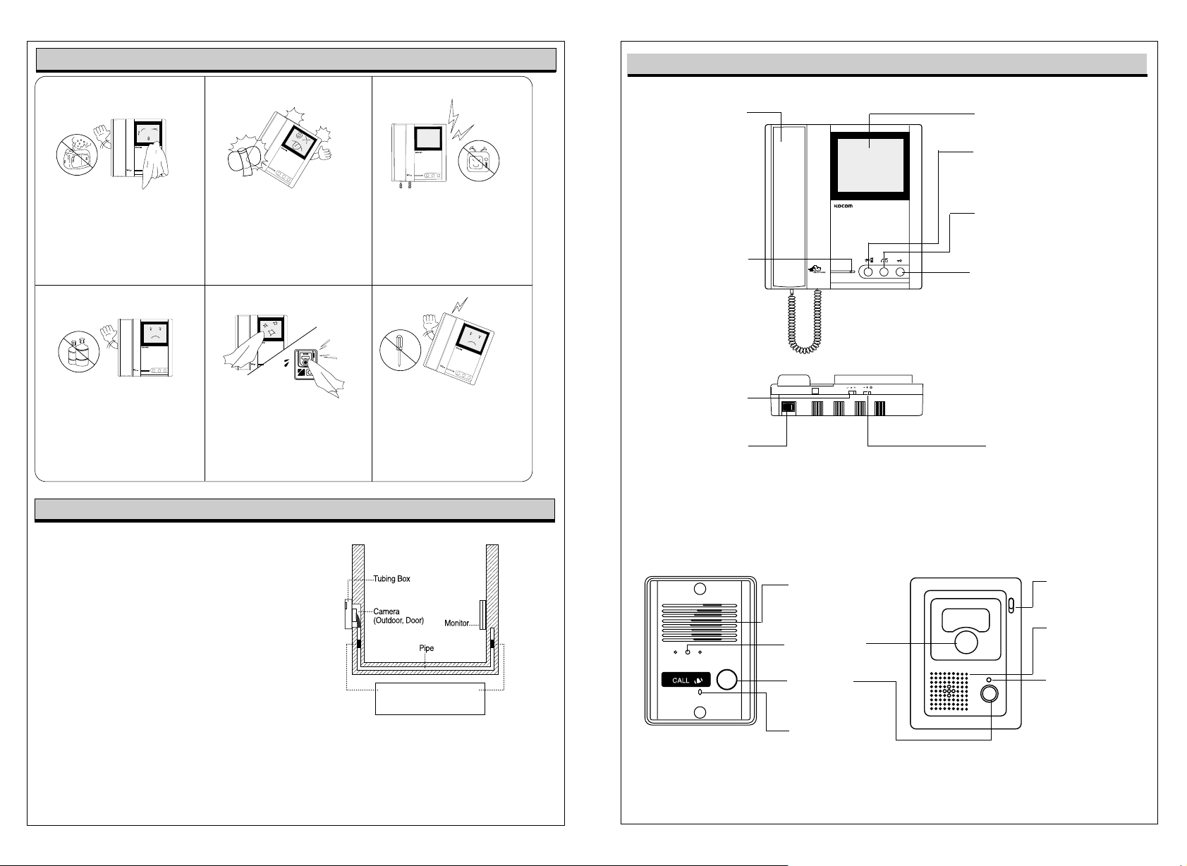
Precautions for Operation
Component’’s Name
Keep away from humidifier and
stove. High temperature and
humidity can cause breakdown.
When cleaning, never use wet
hands, volatile benzene or paint
thinner.
Do not drop monitor or door
camera, and avoid strong
impact.
Keep picture clear by cleaning
camera window frequently with
soft cloths.
Installation Precautions
Monitor and camera must be installed away from direct
light and counter light.
Camera must be installed at a place free from rain.
Standard height of monitor must be 1,450mm~1,500mm
from ground, centered around brawn tube.
Camera should be installed on the wall in which cement
is completely dry.
If installed during winter season at temperature below
-5, condensation might be generated inside monitor and
camera due to temperature difference between indoors
and outdoors. To prevent breakdown due to such
condensation, connection should be made in 2 hours or
more after installation.
Do not install monitor and camera in locations subject to
direct heating as harmful gases may subsequently be
emitted in significant amounts.
Keep away from devices
generating strong magnetic field
(TV, Speaker, etc.) (Picture can
be disturbed or blurred and
breakdown can result)
As this device consists of
electronic precision
components, and high voltage
is generated internally, do not
attempt to disassemble.
Stop up P.V.C. pipe using
adiabatic substances, to
prevent air circulation
Stopping up pipe as above minimizes
temperature difference between indoors and outdoors, and
also eliminates moisture and condensation on door camera
window.
Receiver
used in
communication with
front door camera
LED Indicator
Turned on when
Green:
front door/ inner line
functions are used
Orange: Turned on
lobby/guard functions are
3-Level Volume
Control Switch
Controls volume level
as high/middle/low
Power Switch
■■
KC-D20 Metal Pinhole Camera & KC-B61 Camera
used
Power on/off
Speaker
When visitor calls, the
voice from monitor comes
out of the speaker.
Camera Lens
Clear picture quality realized
by adopting 1/3" CCD
Call Button
By pressing the button, the
related house will be called.
C-Mic
To communicate
with Monitor
4Display
Check visitors
Lobby/Guard Button
Used in communication with
lobby, and call to and
communication with
guardroom
Inner Line/Front Door Button
Used in inner line call and
communication, and check and
communication with front door
Button
Used to open the door. Available
only for the door equipped with
door opener.
Bright
Controls the brightness of
monitor images
C-Mic
To communicate
with Monitor
Speaker
When visitor calls,
the voice from monitor
comes out of the speaker.
Power Lamp
To check power
ON/OFF status
Page 6
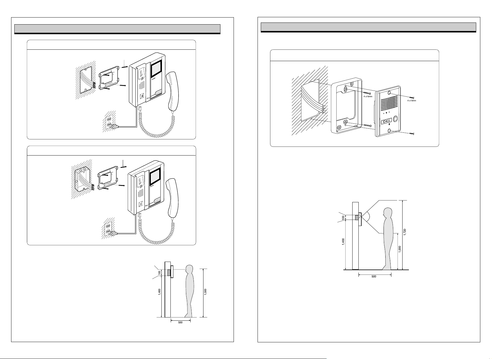
Monitor Installation
Basic Installation method of Monitor
Door camera Installation
KC-D20 Surface-mounting Door Camera Installation
Wall
Wall hanger panel
for fixing Monitor
Screw
When system is attached to 1 rectangular switch box
1 Rectangular
switch box
Wall hanger
panel for
fixing Monitor
Screw
Straight Ahead Installation
After attach the body supporter with 2 screws,
put the Door Camera into the grooves of body supporter,
and then fix it with 2 screws and stick the finishing materials.
Standard Height of Door Camera
Bottom base of
One hall Box
Surface mount
Standard height monitor
Standard height of monitor is ranged 1,450 ~ 1,500
from bottom to the center of monitor screen.
For installation, avoid the places where there is any
excessive humidity,magnetic force, dangerous
chemicals, direct ray of sun, and any places near a
heater which can cause break down.
Center of monitor
Bottom of
1 Rectangular
switch box
(unit:mm)
Standard height of the door camera is 1,400mm 1,450mm from the bottom of one camera
to the floor.
In case that the height of Door camera exceeds the range of min. 1,250mm1,550mm, it is
impossible to control the screen picture with only the lens angle,
and therefore, be careful of the height of camera installation.
(unit:mm)
Page 7
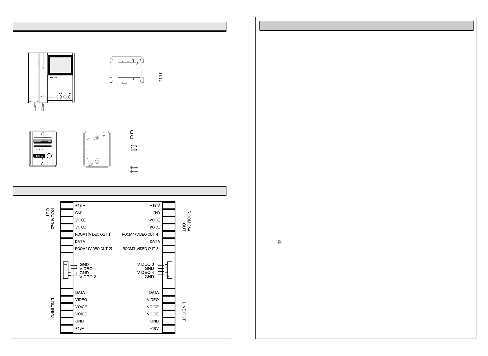
Component
Monitor
Camera Camera & Camera Accessories
Main body supporter
Monitor Accessories
Wall hanger panel
Wall hanger panel is packed in the Monitor
KVS-104P Wiring
Screws for
fixing
4 x 30mm
finishing rubber
Screw for fixing camera
main body supporter
4 x 10mm
Screws for fixing camera
4 x 16mm
Product Specifications
KVM-520 Monitor
Power
Voltage of Operating Power
Tone Sounds of Lobby, Guardroom,
and Inner Line
Monitoring Function
of Front Door Camera
Call Method
Communication Method
Available Image Displaying Time
Available Communication Time:
The Number of Wirings
CRT
Exterior Material
Dimensions
Communication Coverage
Guaranteed Operating Temperature
AC 220V (standby: 2.5W, operating: 20W)
AC 120V (standby: 2.5W, operating: 20W)
DC 17V 1V
Call Sound (Electronic Tone Sound). Sound maintains for 30 seconds when device is called.
By using front door button on monitor, camera monitors front door situations
(however, lobby monitoring function is not available).
Pressing front door camera call button, call sound rings (tone sound 2 times)
Front door image / lobby image display
Calling to house at lobby using preset house No., tone sound rings.
Handset type (two-way)
About 30 seconds from call to front door camera
About 3 minutes under communication state with front door, lobby, and guardroom
Front Door Camera: 4-Line Polar Wiring, over IV 0.65mm applicable
Main Wiring:VOICE1/VOICE2/DATA (3-Line) Polar Wiring, over IV 0.8mm applicable
Power(+/GND) (2-Line) Polar Wiring, over IV 1.2mm applicable
For images, coaxial wiring is used-using COAXIAL 5C-2V
CRT: 4Straight Tube B/W
Non-combustible ABS Resin
191(W) X 217(H) X 52(D)mm
Front Door Camera: 30m when using 0.65mm
Should be within 300m when the same specifications with main wiring is applied
(Same as 4-Line Parallel Method)
Guaranteed Temperature for Monitor: 0C ~50C
KC- 61, KC-D20 Front Door Camera
Input Power
Electricity
Image Device
View engle
Exterior Material
Dimensions
Minimum Illumination
Guaranteed Operating Temperature
(Communication : DC 12V 1V (Max. 3W) Supplies power for monitor
Max. 150mA
CCD
KC-B61 (120KC-D20 (90
Non-combustible ABS Resin
KC-B61 [96(W) X127 (H) X 34(D)mm], KC-D20 [96(W) X127 (H) X 32(D)mm]
0.1Lux(LED ON)
-10C ~50C
Page 8
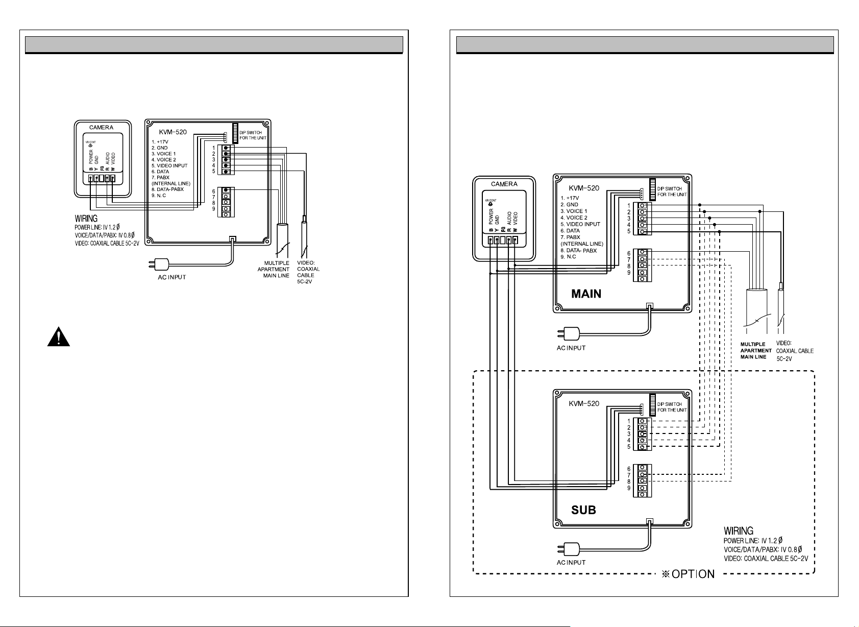
Exterior Wiring Diagram Wiring Diagram
Basic Wiring
Video phone-to- video phone wiring within a house (Installation up to 3 units available)
Cautions
1. No. 6 terminal (data line) is not connected in sub video phone.
2. Terminal No.1, 2, 3, 4, 5, 7 and 8 are used in a form of parallel wiring in additional connection
between main and sub device.
Precautions for Wiring
As incorrect wiring may cause the devices non-operation or poor communication quality, please
carefully conduct wiring work.
When connecting a wiring chord to a terminal, loosen screw, insert the end of the chord into the bottom
part of screw, and tighten the screw.
When fixing wiring chord, use stapler not to cause damage to the chord.
When using existing wiring, please be cautious not to cause disconnection and short-circuit.
Parallel Wiring
Page 9
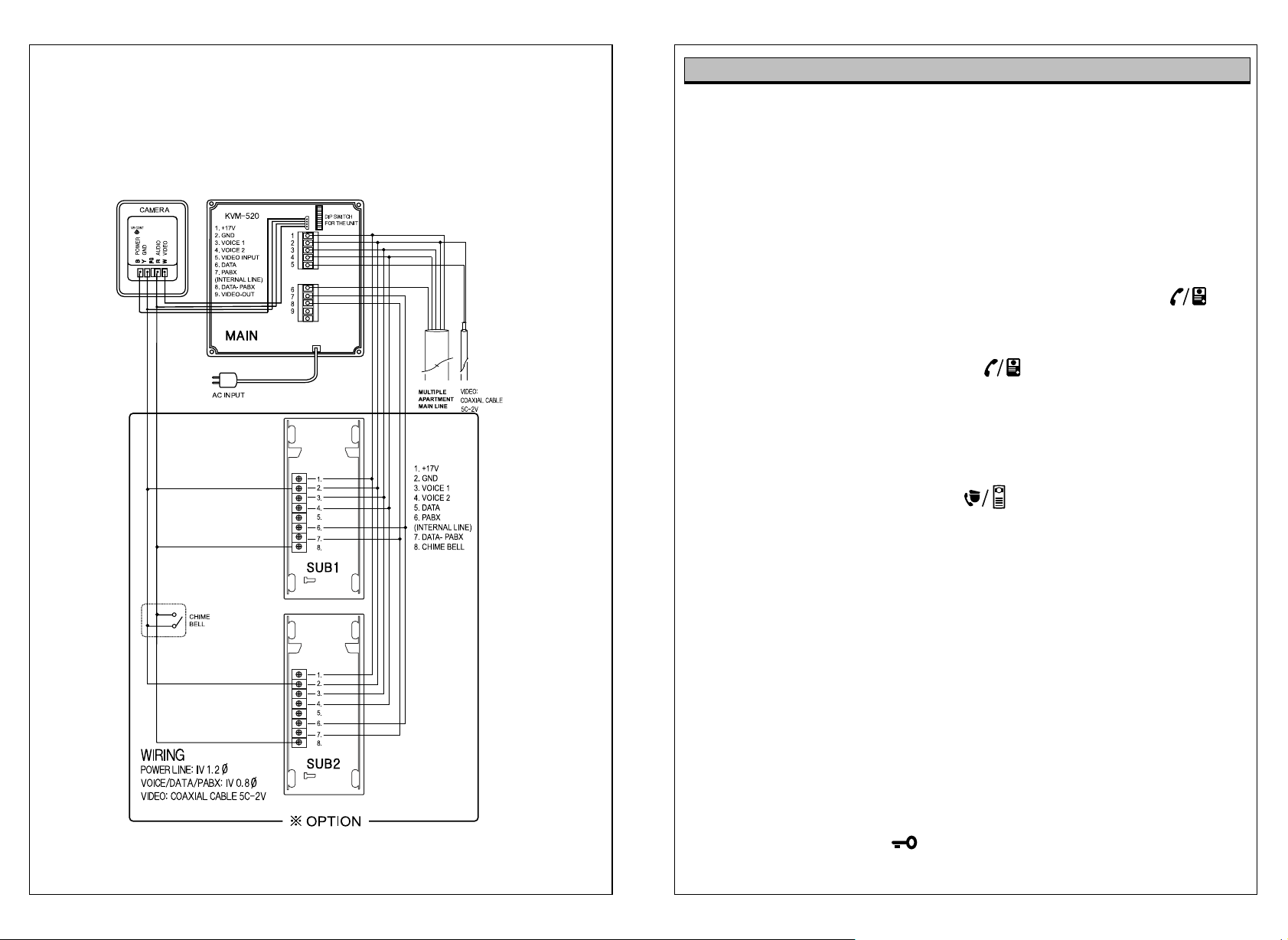
Video phone-to-interphone wiring within a house
Cautions
1. Terminal No. 5 (data line) is not connected in sub interphone.
2. Terminal No.1, 2, 3, 4, 7 and 8 are used in a form of parallel wiring in additional
connection between main and sub device. (Video phone terminals as basis)
Instructions for Operation
Functional Descriptions
Communication with front door when a visitor comes
If a visitor presses the call button on camera.
1. Tone sound rings in indoor monitor, and screen is automatically turned on to display visitor.
2. After picking up the receiver to monitor visitor, communicate with visitor.
(If user does not pick up the receiver, screen is automatically turned off after 30 seconds)
3. After communication with visitor, hang up the receiver.
If user intends to keep communication with visitor going, hang up the receiver and press
button in front side of product. Then, screen is turned on again and users can continue to communicate
with visitors.
When user intends to monitor front door situation : front door/inner line button
1. Pressing front door/inner line button on the video phone, screen is turned on.
2. Picking up handset (receiver), communication with front door is available.
(However, note that inner lines are called while picking up handset.)
Call from guardroom - How to communicate : guard/lobby button
1. Upon tone sound ringing, Orange LED in the front side of video phone flickers.
2. Picking up handset, communication with guardroom available (LED is turned off).
(When receiving call from guardroom while picking up handset, user should press guard/lobby button to
communicate with guardroom.)
Communication between interphone (KIP-603) and front door camera (KC-D20) is not available.
Call to guardroom - How to communicate
1. Picking up the handset and pressing guard/lobby button, tone sound rings.
2. Picking up handset at guardroom, communication with guardroom is available
(available communication time: 3 minutes). Hang up the handset, communication is automatically cut off.
Call from lobby - How to communicate
1. Receiving call, orange LED in the front side of video phone flickers (Tone sound rings for 30 seconds).
2. Picking up the handset, communication with lobby is available (orange LED is turned off).
(When receiving call from lobby while picking up handset, user should press guard/lobby button to
communicate with lobby.)
3. If user presses door open button while communicating with lobby, common front door
equipped with opener is opened.
Page 10
Call from inner lines
1. Receiving call, Green LED in the front side of video phone flickers.
2. Picking up the handset, communication with inner line is available (Green LED is turned on).
(When receiving call from inner line while picking up handset, user should press guard/lobby button to
communicate with inner line.)
3. Available communication time with inner line is for 3 minutes. If 3 minutes elapses, communication is
automatically cut off.
Call to house using inner line How to communicate
1. Pick up the handset and press button (available call time is for 30 seconds).
2. Picking up handset at newly installed house device, communication is available. Communication maintains
for 3 minutes. Hanging up the handset, communication is cut off.
With 3-level volume control switch, user can arbitrarily control the volume level into high, middle, or low.
For every function, call signal maintains for 30 seconds. As 30 seconds elapses, call signal and screen
returns to standby mode.
Every communication maintains for 3 minutes. As 3 minutes elapses, device returns to standby mode.
Instructions for Operation
Model: (KLP-100), Functional Specifications
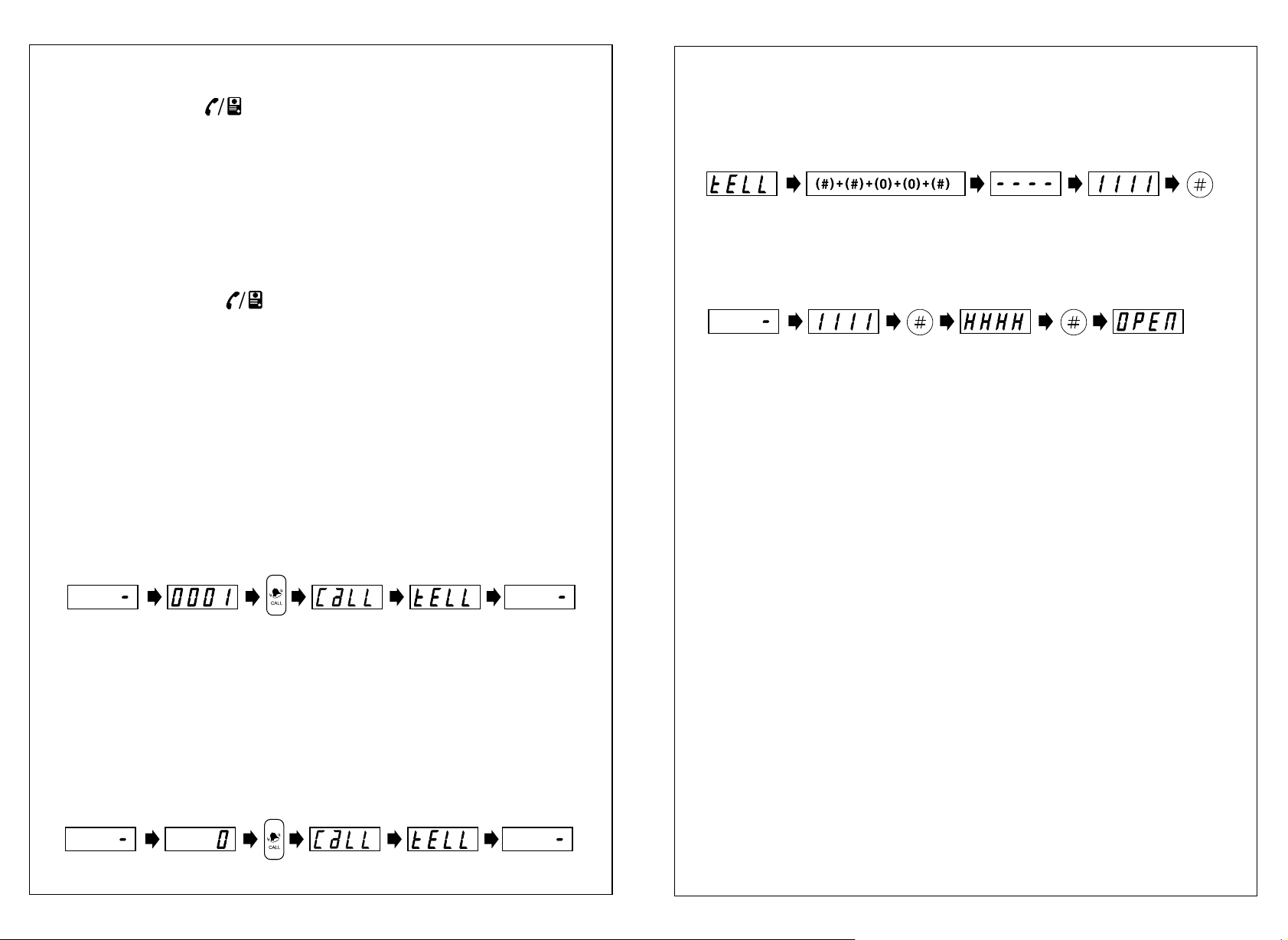
Call to house
When a visitor calls to house using lobby phone, press house number.
Password Change
(Password change function is only available during the call with house.)
Pressing # # 0 0 #during the call with house, is displayed.
Input new password and press button.
Door open using lobby phone with password
Pressing house number + # + password + #designated by the house, door is automatically opened.
e.g) Press house number 1111and password.
Call to house
1. Press the house number on the lobby phone.
(If pressing house number once more for call sound outputs, call is cancelled.)
(As separate cancel button is not available on these devices, press house number once more to cancel the
call.)
2. With call sound rings, house is called.
(In the case of newly installed lobby phone, call from and communication with guardroom, or house is on
the line, devices output absence melody and returns to standby mode.)
> Pressing call button, call sound rings and house is called.
> If the house responds to the call, communication is available for 3 minutes.
(Pressing door open button during the communication, opener installed common front door is opened.)
> When communication is ended, device returns to standby mode.
Call from lobby phone to guardroom
Pressing 0and call button on the lobby phone, guardroom is called and lobby ID is displayed in guardroom
device.
> Communication with guardroom maintains (for 3 minutes). When communication is ended, device returns
to standby mode.
In the event that opener operates during the communication with house
1. If door open button is pressed at the house during the communication with lobby phone, common front
door is opened.)
(Opener specification: within DC12V300mA - maintains 2 seconds)
DIRECT BUTTON TYPE LOBBY PHONE OPERATION
Call to the house
- Press the certain call button for the house.
Then, call signal (Tiriri~) sounds and it makes the call to the certain house.
- While making call to the house, if the same call button is pressed once again, the call is
cencelled. (There is no certain cancel button)
- In case, it is on the line with other lobby phone or guard master, absence signal (Ti~Ti~ Ti~)
sounds and it is on the mode of stand-by.
Page 11
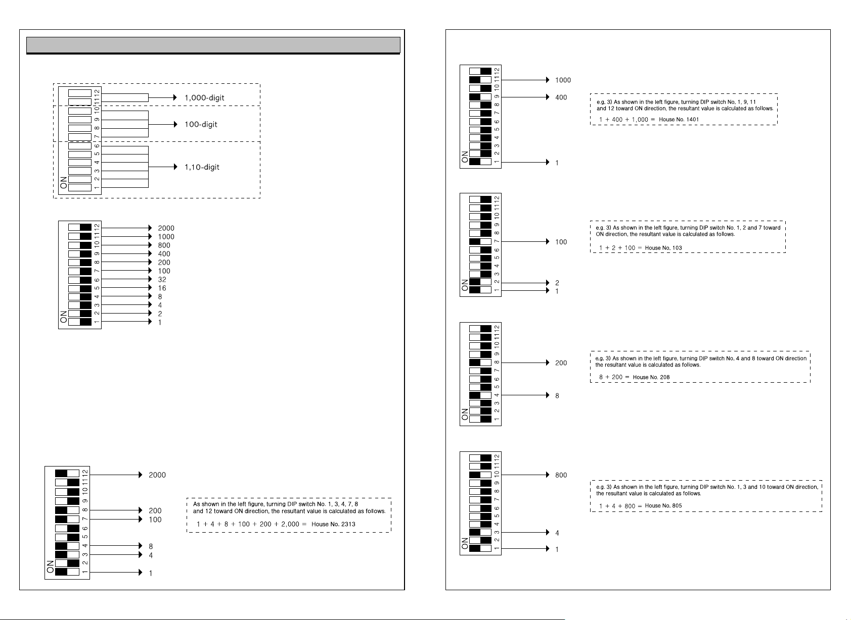
DIP Switch Setting at House Interphone and Video Phone
e.g. 1)
e.g. 2)
Numbers by the figure indicate the number set when
all switches move toward ON direction.
e.g. 3)
1. Above figure, turning all DIP switches from No.1 to No. 12 toward ON direction, numbers set by DIP
switches are summed up.
e.g. 1) Above figure, turning switch No.1 and No. 2 toward On direction, value is set at 3 (1 + 2 = 3) since
numbers set by switches are 1 and 2.
e.g. 2) Above figure, turning switch No.1 and No. 3 toward On direction, value is set at 4 (1 + 3 = 4) since
numbers set by switches are 1 and 3.
e.g. 3)
Page 12
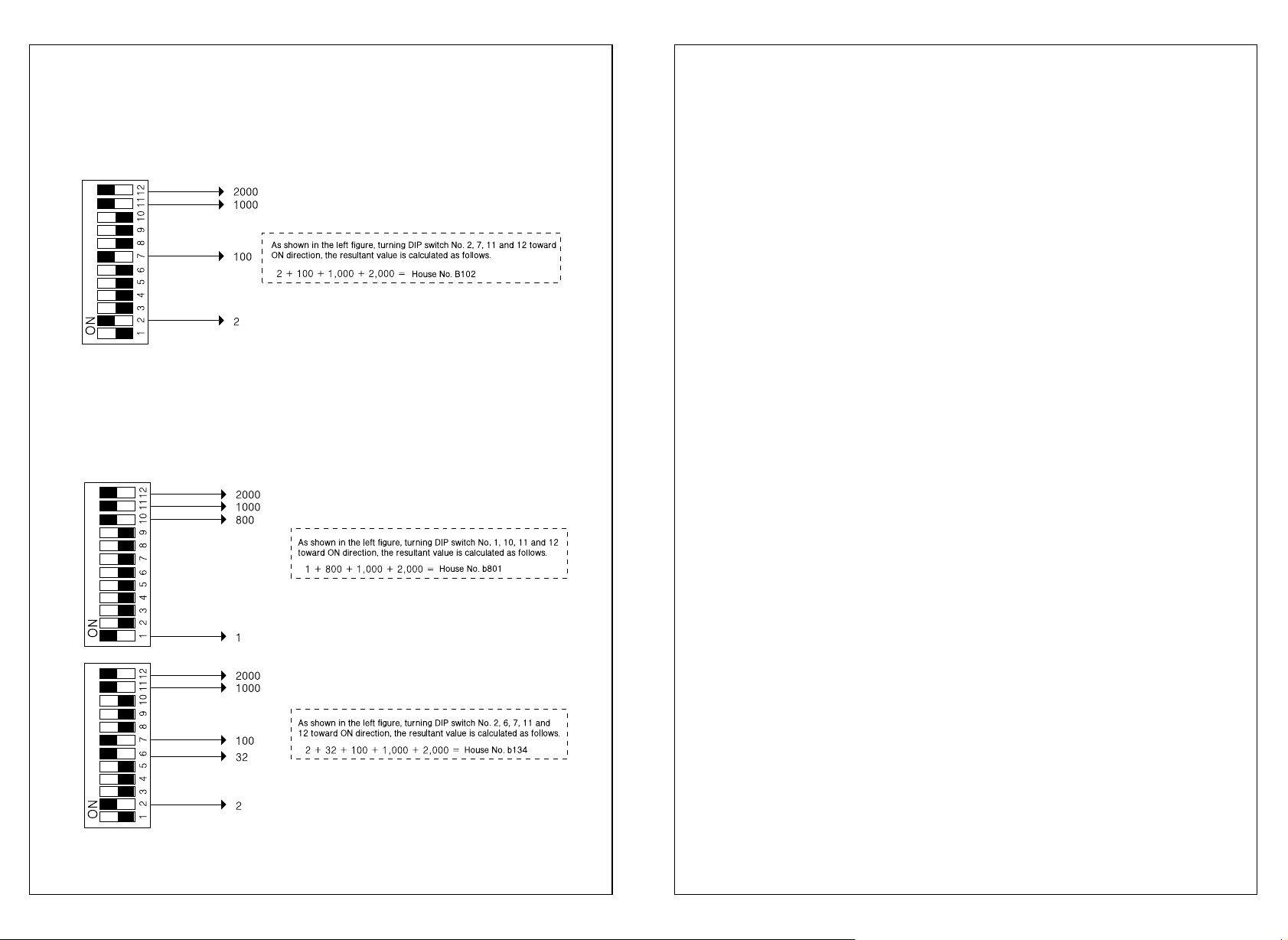
2. For basement floors, DIP switch No. 11 and 12 are generally set toward ON direction.
In this case, the value of DIP switch setting is 3,000 (1,000 + 2,000). However, program uses 8with
similar shape of B(Basement) to indicate basement floors. Thus, value is not 3,000 but 8,000.
3. If DIP switches are set as in the above example, press 8102to call the house using guardroom master
or lobby phone.
In addition, house number is displayed as small character b102in FND of guardroom master or
lobby phone.
4. Precautions for DIP Switch Setting (House No. Setting)
1) After setting DIP switches, device power should be reset.
(In power switch ON state, DIP switches cannot be set.)
2) For setting basement floors, switch No. 11 and 12 should be ON state.
3) For direct dialing type lobby phone, up to 12 houses can be set.
Thus, when DIP switches of house interphone and video phone are set, available houses are also 1 to 12 in
number.
4) If user wants to use interphone or video phone as sub-phone, all DIP switches should be in OFF state.
5) When user sets DIP switches, excessive impact on DIP switches may cause abnormal or erroneous
operation of device.
 Loading...