

Page 1
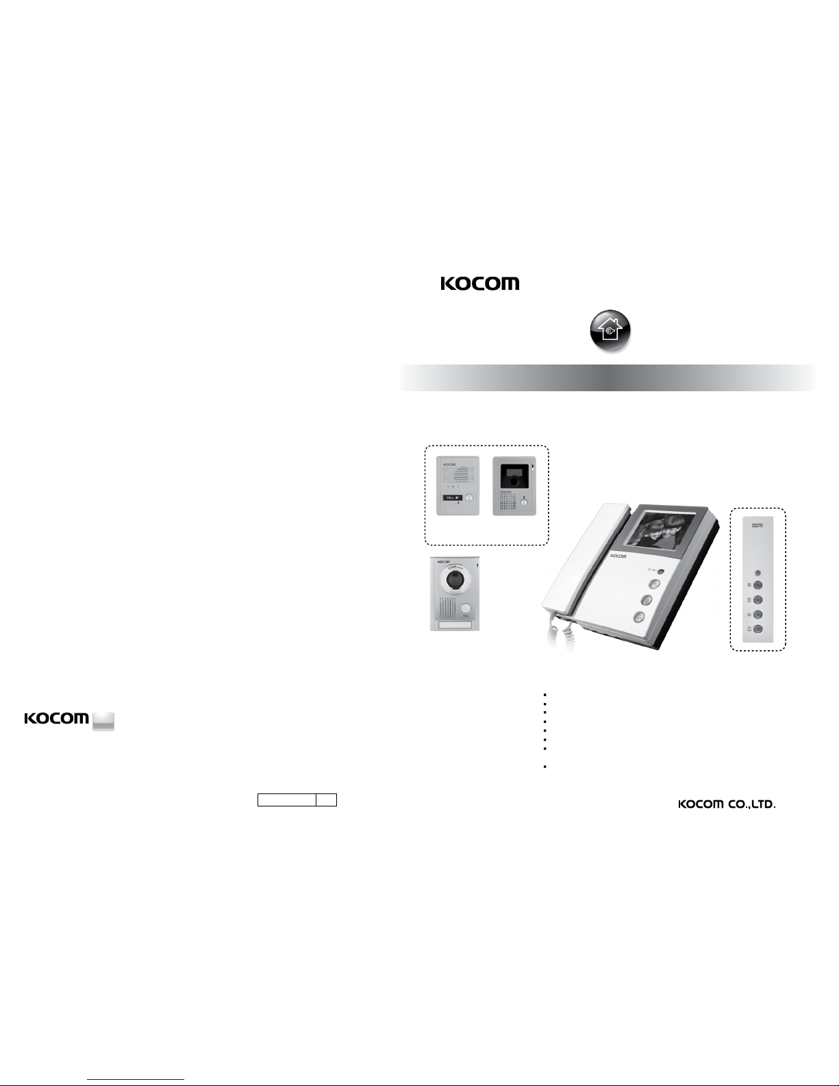
KVR-300 [OPTION]
KVM-301 / KVM-D301 09.04
KVM-301 / KVM-D301
SINCE
1976
KOREACOMMUNICATIONS CO.,LTD
4" B/W Flat CRT
Communication with door and door monitoring
Door open during communication
Intercom function between extended indoor units
Surface mount type installation
External 64 cut memory equipment (KVR-300) connection
Connection with up to 2 door cameras,
2 monitors and 2 sub audio phone (KDP-602G)
5 melody selection
[ Operating Installation Manual ]
KVM-301 / KVM-D301
KC-MB30
KC-D20 [OPTION] KC-C63 or KC-B61
[OPTION]
http://www.kocom.com
E-mail : [email protected]
This manual is based on the date as shown in the right and specifications are subject to
change without notice for quality improvement
Page 2
4
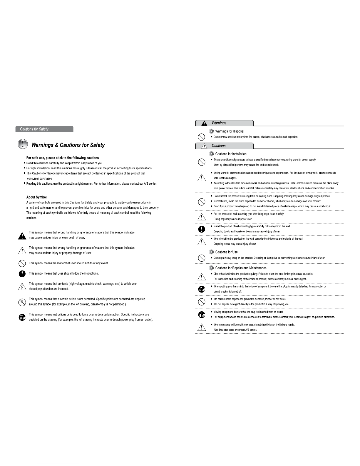
Cautions for safety
8
Monitor installation
9
Door camera installation
10
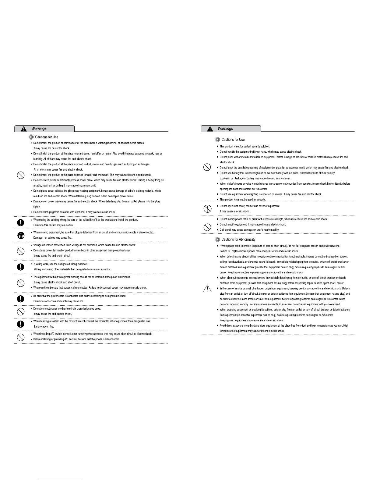
Precautions for operation
10
Installation precautions
11
11
12
13
Components
Specifications
Name of each part
How to operate
14
Interlocked device
21
Operational descriptions of special functions
21
KVR-300 User's manual
22
Installation (KVR-300)
16
Wiring Diagram [Cable requirement]
19
Wiring Diagram [CCTV Camera A type]
22
23
How to operate (KVR-300)
Warranty Card
■
■
■
■
■
■
■
■
■
■
ContentsContents
20
Wiring Diagram [CCTV Camera B type]
Page 3
54
Page 4
7 6
Page 5
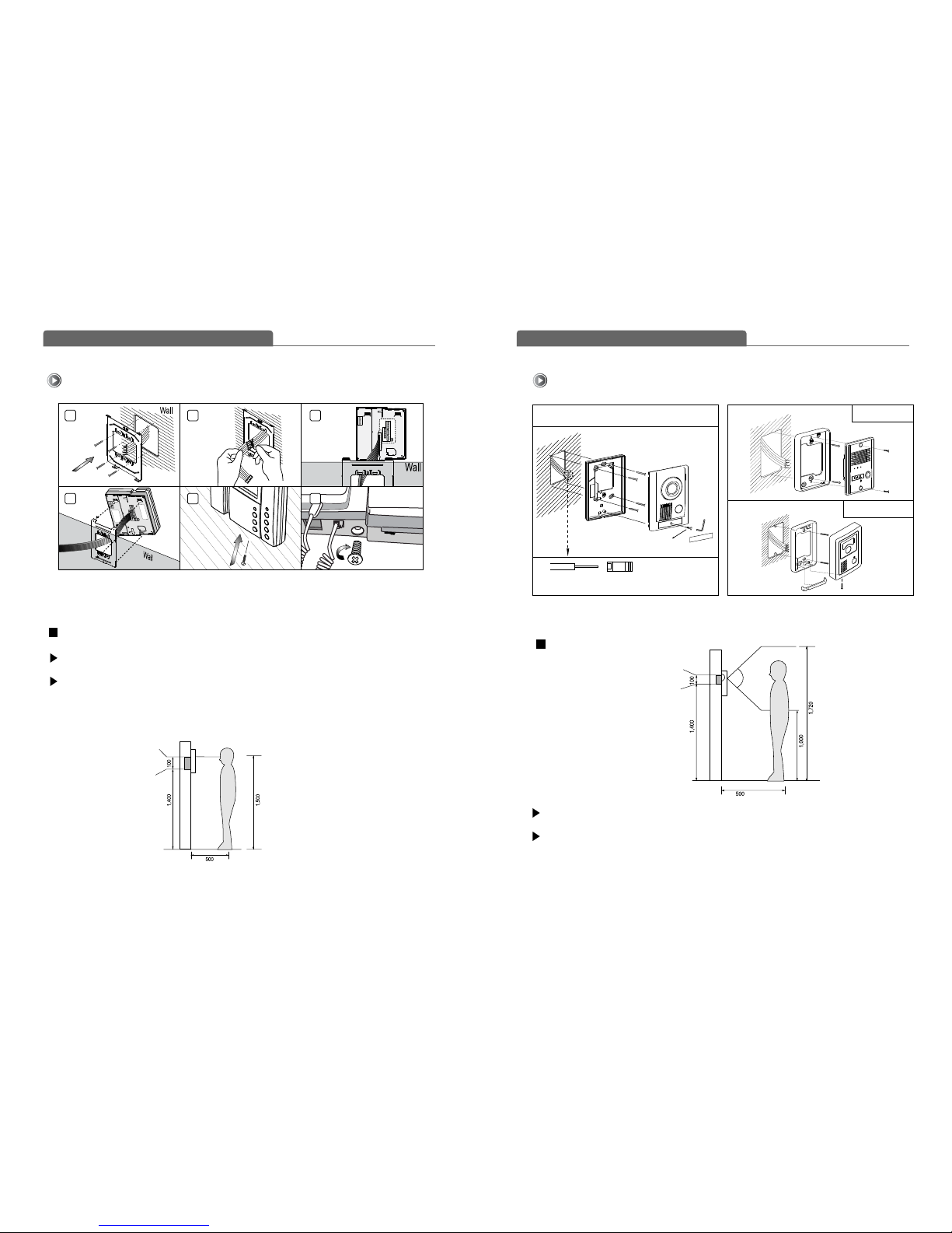
Door Camera Installation
KC-MB30
Standard Height of
Door Camera
(unit:mm)
B
o
t
t
o
m
b
a
s
e
o
f
O
n
e
h
a
l
l
B
o
x
Surface mount
Basic Installation method of Monitor
S
t
a
n
d
a
r
d
H
e
i
g
h
t
o
f
M
o
n
i
t
o
r
(unit:mm)
Bottom of
1 Rectangular
switch box
Center of monitor
R
ea
r
1 2 3
4 5
Rear
END
6
Wall hanger
pannel
Wall
3X8mm
Screw
4X25mm
Screw
4X25mm
Screw
4X8mm
Screw
Wrench
Name plate
A
fte
r
f
i
x
t
h
e
re
a
r
b
r
a
c
k
e
t
w
i
th
4
s
c
re
w
,
p
u
t
th
e
D
o
o
r
C
a
me
ra
i
n
t
o
t
h
e
g
ro
o
v
e
s
o
f
r
e
a
r
b
ra
c
k
e
t
,
a
n
d
t
h
e
n
fi
x
i
t
w
i
t
h
h
e
x
a
g
o
n
s
c
r
e
w
s
a
n
d
s
ti
c
k
th
e
f
i
n
i
s
h
i
n
g
ma
t
e
r
i
a
l
s
.
Rear Bracket
S
t
a
n
d
a
r
d
w
i
r
e
s
t
r
i
p
s
p
e
c
i
f
i
c
a
t
i
o
n
:
6
~7
m
m
S
t
a
n
d
a
r
d
w
i
r
e
(
A
W
G
)
:
1
6
~
2
4
(
0
.
5
m
m
~1
.
2
m
m
)
C
a
m
e
r
a
T
e
r
m
i
n
a
l
B
l
o
c
k
Monitor Installation Door camera Installation
Standard height of monitor is 1,450~1,500mm from bottom to the center of monitor screen.
For installation, avoid the places where there is any excessive humidity, magnetic force, dangerous
chemicals, diret ray of sun, and any places near a heater which can cause break down.
Standard height of door camera is 1,400~1,450mm from the bottom of one camera to the floor.
In case that the height of Door camera exceeds the range of min. 1,250mm ~ 1,550mm, it is
impossible to control the screen picture with only the angle, and therefore, be careful of the
height of camera in insrallation.
KC-D20
KC-C63 / KC-B61
Wall
Screw(4X10mm)
Screw
(4X10mm)
Screw
(4X16mm)
Screw(2.6X6mm)
baby support
Upward support
Wall
Camera
front
Camera
front
Camera front
98
Page 6
1
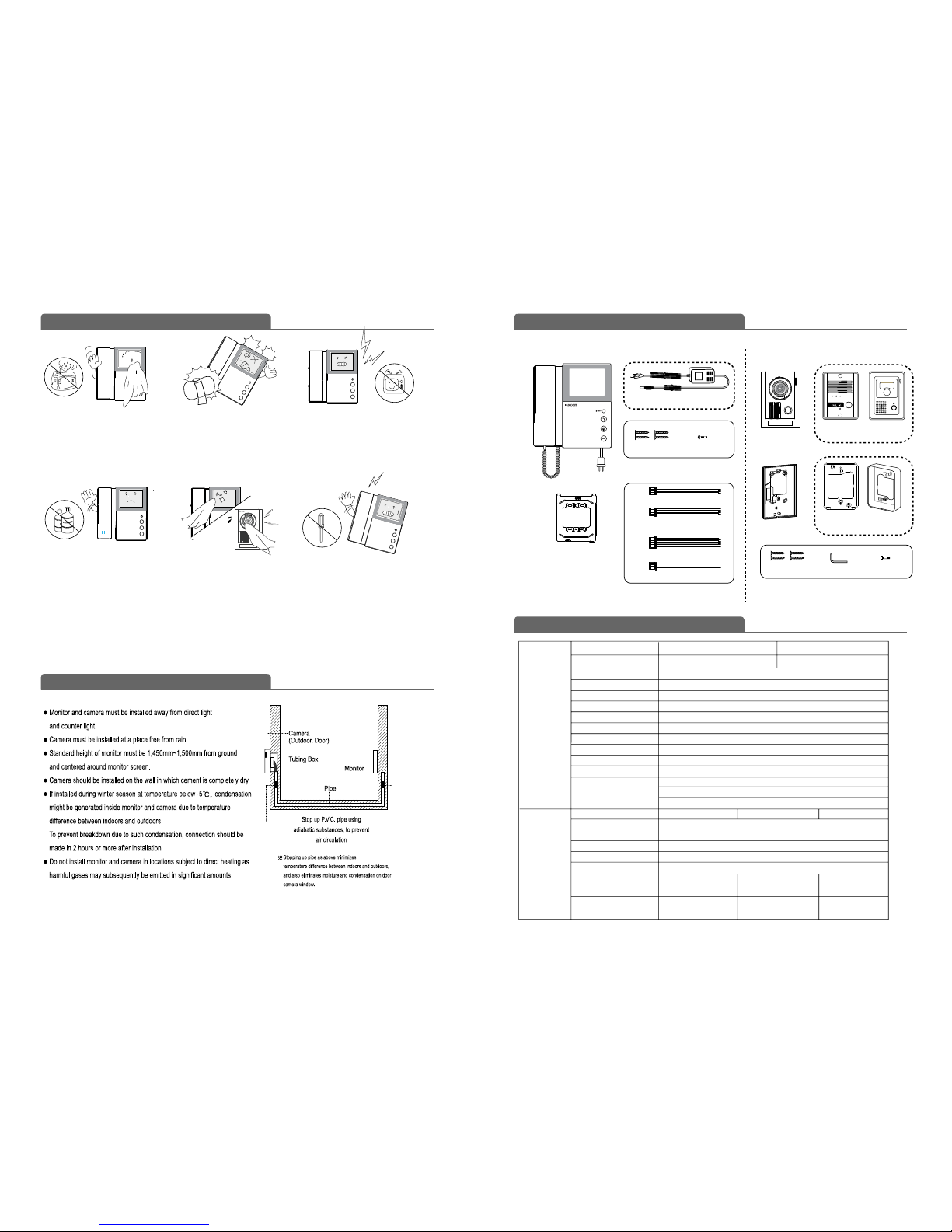
Specifications
Installation Precautions
ComponentPrecautions for Operation
MONITOR
Door Camera
Min. Illumination
Dimension
DC12V±1V
Max: 3W (In Load)
-10℃ ~ +50℃
0.1Lux (LED ON)
110(W)x158(H)
x39(D)mm
KC-MB30 KC-D20 KC-C63 / KC-B61
Diagonal 120
(angle adjustable)
。 。 。
Diagonal 90
Power Source
Power Co nsumption
Communication System
Call Sound
Wiring
SMPS AC 90-240V (50Hz/60Hz) DC15V ± 1V 1.2A
KVM-301 KVM-D301MODEL NO.
MODEL NO.
Max: 20W, Standby 1.6W
0℃~ + 40℃
Duplex handset conversation
Melody Sound
4 Wires (camera), 6Wires (audio phone), 8Wires (video phone)
Dimension
210 (W) x 222(H) x 57(D)mm
Keep away from humidifier and
sto ve . H igh te mpera ture and
humidity can cause breakdown.
Do not drop monitor or door
camera, and avoid strong
impact.
Keep away from devices
generating strong magnetic field
(TV, Speaker, etc.) (Picture can
be disturbed or blurred and
breakdown can result)
When cleani ng, n ever use we t
hands, volatile benzene or paint
thinner.
Keep pictur e clear by cleaning
camera window frequently with
soft cloths.
As this device consists of
electronic precision
components, and high voltage
is generated internally, do not
attempt to disassemble.
Wall hanger bracket
Wall hanger bracket is
packed in the Monitor
Monitor
Door Camera
KC-MB30
KC-D20 KC-C63 or
KC-B61
KC-MB30
KC-D20 KC-C63 or
KC-B61
Rear Bracket
4X25mm 4ea 3X8mm 1ea
※ According to outside environment, you may view the images somewhat unclear.
However, they do not result from any defect or trouble of the product.
Screws for fixing Monitor
Wire
Operating Temperature
Operating Temperature
4 Pin cable for camera
6 Pin cable for sub audio phone
(KDP-602G)
8 Pin cable for monitor extension
2 Pin cable for Door Opener
8P
4Px2
6P
2P
4X25mm 4ea
4X8mm 1ea
"L" Wrench
Screws for fixing Camera
CRT
Mount Type
Angle of Lens
Surface mount
Max.Wiring Distance TIV 0.8mm Cable=100m, UTP CAT5=100m
Indoor Unit Connection KDP-602G (Audio phone), KVM-301 (B/W monitor)
Camera Connection KC-MB30, KC-MB31,KC-D33, KC-D20, KC-MB20, KC-B61,
KC-MB12, KC-MB14, KLP-302, KLP-304, KLP-306, KLP-308,
KLP-312, KLP-P302, KLP-P304, KLP-P306, KLP-P308, KLP-P312
4" flat tube
Power Consumption
Power Source
(power from Monitor)
96(W)x127(H)
x32(D)mm
Diagonal 120
95(W) x 127(H)
x 34(D)mm
DC 15V Adapter (DCtype)
1110
Page 7
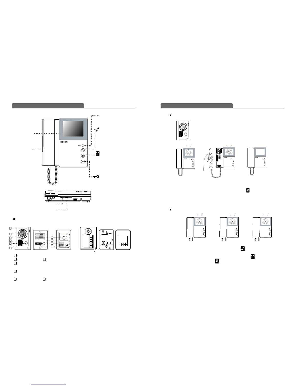
Door Camera
KC-MB30
KC-D20 KC-D20KC-C63 / KC-B61 KC-C63 / KC-B61
KC-MB30
4 inch screen
Toidentify visitor
Handset
Tocommunica te
with door camera.
Power LED / Set button
Setting of special functions
SET button
Extension button
Extended monitor or call & answer
to extended monitor
or doorphone
Camera button
Identification and communication
with a visitor at door.
Door Open button
Door opening during
communication
While melody sounds from the monitor, the image of a visitor at door is displayed.
Pick up the handset to communicate with a visitor at door.
In case the handset is used with extended indoor units, press camera button for communication.
Hang up the handset to finish communication.
Communication with door is available for up to three minutes.
When visitor presses the call button of door camera, the call from the door panel
keeps ringing for 2 minutes. But monitor screen will be turned on for 1 minute.
Monitor button won't fuction during the rest 1 minute.At this time, when holding
the handset, the screen will be turned on and communication will be available.
How to operate (Instruction for operating)
Name of each part
3-level brightness control knob
3-level melody volume control knob
To view the state of door without communication, p ress camera button and view the image from door
camera 1 through the screen.
To view the image from door camera 2 through the screen, press camera button once more.
To end door monitoring, press camera button once more.
1312
C-Mic : To communicate with Monitor
Camera Lens LED
Speaker: When visitor calls, the voice from
monitor comes out of the speaker.
Call Button: By pressing the button, the related
house will be called.
Name plate Screw cap
Camera monitoring-Don't need to hold handset
Communication with door camera
Door camera monitoring is available for up to one minute.
FG(FRAME GROUND)
①
②
③
④
⑤
⑥
⑦
⑧
① : VCC
② : GND
③ : Audio
④ : Video
⑤&⑥ : Door (Non-Polarity)
⑦
:
Camera angle knob
(Only KC-MB30)
⑧ : Wire clamp
1
2
3
4
4
2
5
5
6
6
1
2
3
4
5
7
1
① ② ③ ④
① ② ③ ④
Page 8
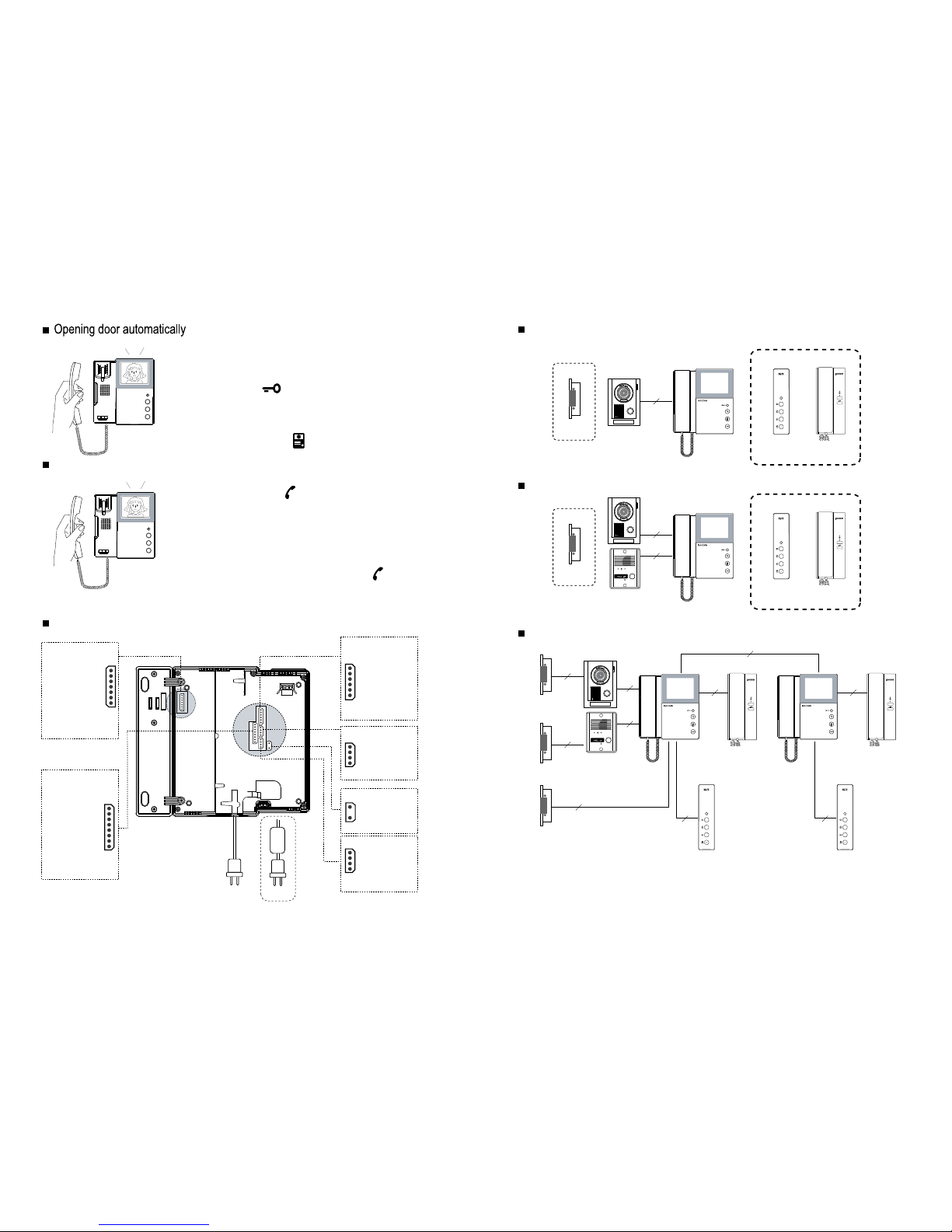
When the device has an extended monitor or door-phone, pick up the
handset and press Extension button.
Then, tone ring sounds from the monitor.
At this time, the device shifts to communication mode automatically.
On the other hand, when an indoor call is received from the extended
monitor or door-phone, pick up the handset. Then, communication is
made available immediately.
In the state of picking up the handset, press Extension button for
communication.
Indoor communication is available for up to three minutes.
For this purpose,automatic DC doorlock shouldbe installed on the
door and connected to camera or monitor.
If you press Door open button during the communication with door,
the door is opened automatically.
After opening the door, you may end the communication by hanging up
the handset or pressing camera button.
Extension Call & Communication
Name of Each Connection port
4 WIRE
OPTION
OPTION
Door Opener
Door Opener
Extended Memory Unit
KVR-300
Extended Memory Unit
KVR-300
Extended Memory Unit
KVR-300
Doorphone
KDP-602G
OPTION
4 WIRE
4 WIRE
4 WIRE
4 WIRE
6 WIRE
2 WIRE
Door Opener
External Power Input
Door Opener
External Power Input
2 WIRE
Door Opener
External Power Input
2 WIRE
8 WIRE
6 WIRE
Monitor 2
KVM-301
KVM-D301
Monitor 1
KVM-301
KVM-D301
7 WIRE 7 WIRE
OPTION
Extended Memory Unit
KVR-300
Doorphone
KDP-602G
Doorphone
KDP-602G
Doorphone
KDP-602G
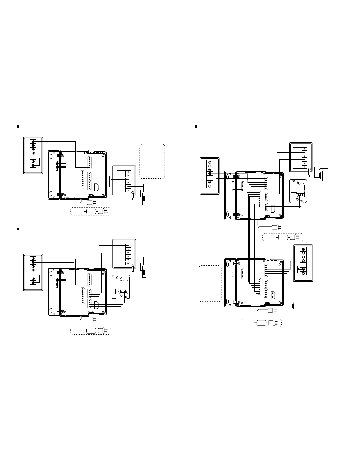
1 Camera : 1 Monotor Connection
2 Cameras : 1 Monitor Connection
System configurations
Extended Memory
Unit port
+12V
GND
CALL SIGNAL
VIDEO IN
VIDEO OUT
NC
PLAYSIGNAL
Extended
monitor port
DATA
CA2 VIDEO
CA2 AUDIO
CA2 Vcc
CA1 VIDEO
CA1 AUDIO
GND
CA1 Vcc
Door Opener(DC)
LINE 1
LINE 2
DOOR OPEN(-)
DOOR OPEN(+)
+12V
I/P AUDIO
GND
DATA
Extended
Interphone port
Camera 1
VIDEO
AUDIO
GND
VCC
Camera 2
VIDEO
AUDIO
GND
VCC
For AC
90V~240V
or
Adapter
①
②
③
④
⑤
⑥
⑦
⑥
⑤
④
③
②
①
④
③
②
①
④
③
②
①
②
①
⑧
⑦
⑥
⑤
④
③
②
①
1514
8
1
4
1
2
1
4
1
6
1
1
7
For DC
Page 9
AC POWER CABLE
AC 90V-240V
※Option
DC
Power
Door
opener
1
8
Extended
Memory Unit
KVR-300
AC POWER CABLE
AC 90V-240V
KDP-602G
※Option
※Option
①
②
③
④
⑤
⑥
7
1
7
1
1
1
1
2
4
1
6
4
Extended
Memory Unit
KVR-300
Extended
Memory Unit
KVR-300
KDP-602G
AC POWER CABLE
AC 90V-240V
DC 15V
※Option
※Option
①
②
③
④
⑤
⑥
Adapter
AC POWER CABLE
AC 90V-240V
7
1
7
1
1
1
1
1
8
4
1
6
4
KDP-602G
CAM 2
KC-MB30
KC-D20
※Option
※Option
※Option
DC
Power
Door
opener
①
②
③
④
⑤
⑥
①
②
③
④
⑤
⑥
CAM 1
CAM 1
KC-MB30
※Option
DC
Power
Door
opener
①
②
③
④
⑤
⑥
7
1
7
1
1
1
1
1
8
4
1
6
4
Extension
Monitor
DATA
CAM2 VIDEO
CAM2 AUDIO
CAM2 Vcc
CAM1 VIDEO
CAM1 AUDIO
GND
CAM1 Vcc
⑧
⑦
⑥
⑤
④
③
②
①
CAM 1
① : VCC
② : GND
③ : Audio
④ : Video
⑤&⑥ : Door
(Non-Polarity)
FG
FG
1 Camera : 1 Monitor Connection Wiring Full System Wiring / 2 Cameras : 2 Monitors Connection Wiring
2 Cameras : 1 Monitor Connection Wiring
DC 15V
Adapter
DC 15V
Adapter
Extended
Memory Unit
KVR-300
KDP-602G
CAM 2
KC-MB30
KC-D20
※Option
※Option
※Option
DC
Power
Door
opener
①
②
③
④
⑤
⑥
①
②
③
④
⑤
⑥
CAM 1
7
1
7
1
1
1
1
1
8
4
1
6
4
FG
DC 15V
Adapter
1716
① ② ③ ④
① ② ③ ④
Page 10
Wiring Diagram
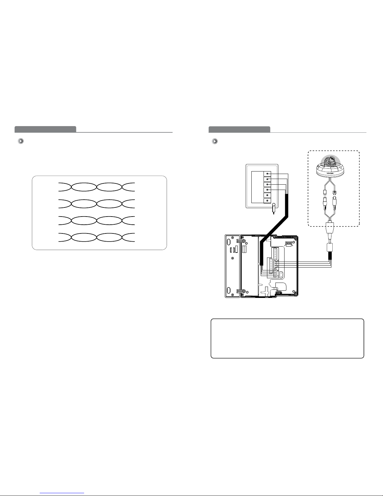
Wiring Diagram [Cable requirement]
1918
■
Upto100M: CAT5 cable
■
Upto50M : TIV 0.65㎟cable
■
Upto100M: Over TIV 0.8㎟cable
■
Upto150M: TIV0.8㎟cable + RG-59/ U
RG-59 / U (Coaxial cable)for Video signal
(Connect core to Video& shieldto GND)
Based on distance from a camera to the monitor
※※CAT5 wire configuration
In case of more than 50m of CAT5 cable length, the screenand voice qualitycan get lower.
But the sympthom is not a kind of fault. So less than 50m is recommended.
Orange
W / Orange
① VCC
double up
Green
W / Green
② GND
double up
B lue
W / Blue
③ Audio
double up
Brown
W / Brown
④ Video
double up
Wiring Diagram
Wiring Diagram [CCTV Camera A type]
A. In case the power consumtion of CCTV camera is below 200mA (DC12V) and in distance
below 50M, you can use monitor power to CCTV camera.
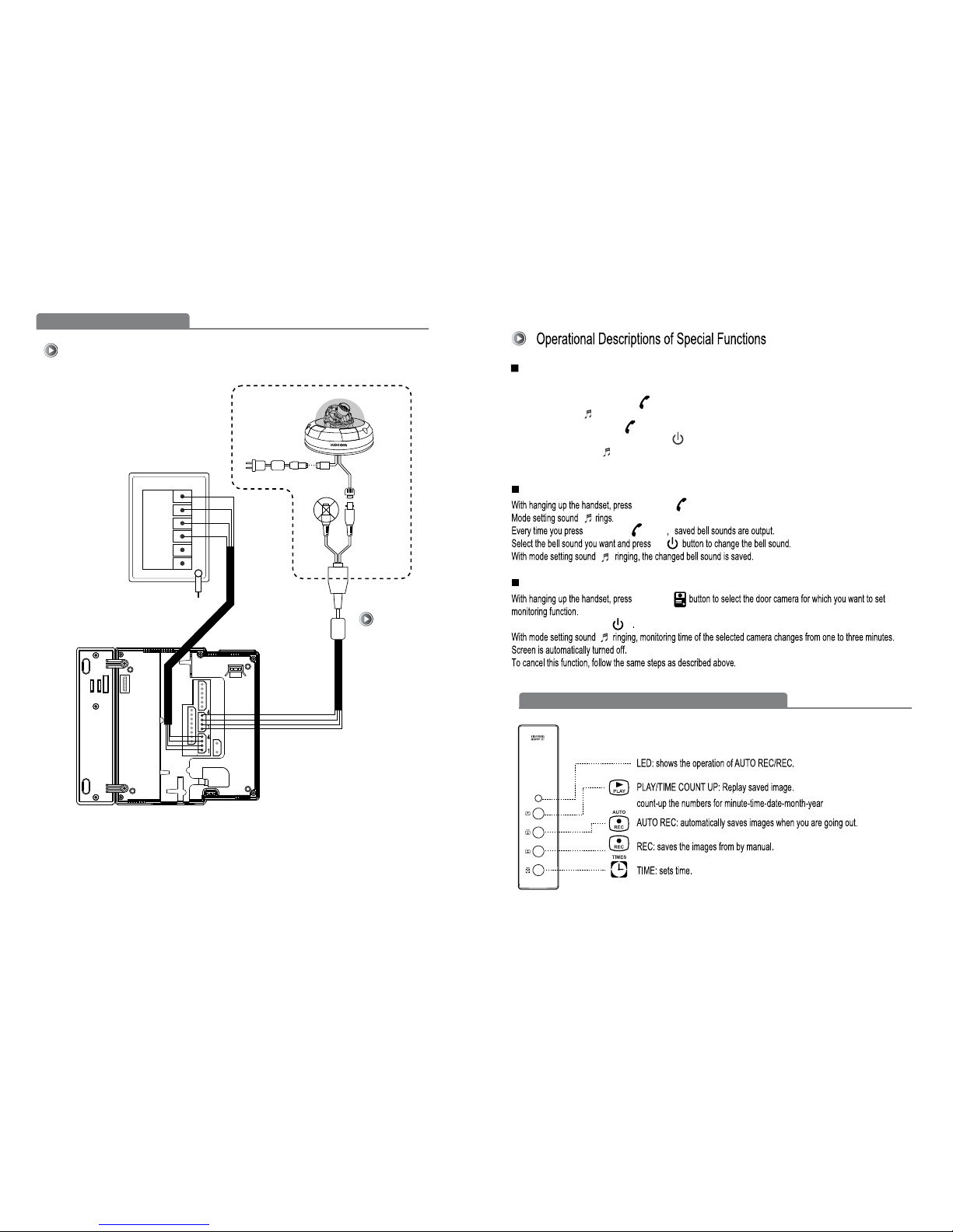
B. In case the power consumption of CCTV camera is over 200mA (DC 12V) and distance
between CCTV camera and monitor is over 50M, the addional power supply shoud be used
for CCTV camera.
KC-MB30
CAM1
①
②
③
④
⑤
⑥
Video
BNC
CCTV
A type
DC
Jack
FG
Main monitor
Page 11
2120
Wiring Diagram
Wiring Diagram [CCTV Camera B type]
B type
ADAPTOR
Video
BNC
CCTV
KC-MB30
CAM1
①
②
③
④
⑤
⑥
FG
Main monitor
With hanging up the handset, select the camera 1 or camera2 using monitoring function.
While screen is on, press Extension button for three seconds.
Mode setting sound rings.
Every time you press Extension button, saved bell sounds are output.
Select the bell sound you want and press set button to change the bell sound of related door camera.
With mode setting sound ringing, the changed bell sound is saved.
Screen is automatically turned off.
Door Camera Call Melody Selection (5 Melody)
Extension Call Melody Selection (5 Melody)
CCTV Monitoring (3min)
Ex
t
e
n
s
i
o
n b
u
t
t
o
n
E
xte
n
sio
n
b
u
tt
o
n
ca
m
e
r
a
CCT
V
set
While screen is on, press set button for three seconds.
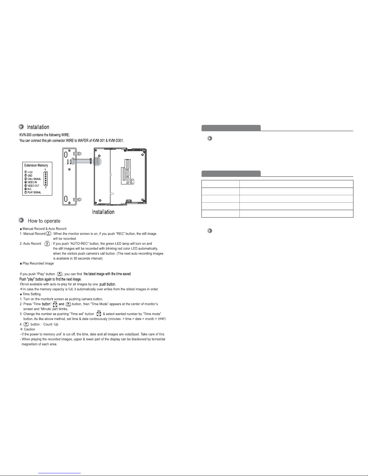
External Memory Equipment (KVR-300) User's Manual
Page 12
2322
Warranty
Warranty Card
KOCOM Warranties the original purchaser of this product as follows.
For after-Sale service, have the following ready when you
contact our branches.
PRODUCT
MODEL
DATE PURCHASED
WARRANTY PERIOD
AGENCY ADDRESS
1) This product is produced under strict quality control and inspection procedures.
2) If this product breaks down during proper use as a result of product defect, KOCOM
will repair it within one year from date of purchase free of charge.
3) The following cases will be subject to charge, even during warranty period:
a. Breakdown during transport, or through careless treatment, by consumer.
b. Breakdown cause by unauthorized repair, or system modification.
c. Breakdown caused by natural disaster or power disorder.
1. Name of the product.
2. Model number of the product.
3. The area of problem.
4. Phone number and address at which you can be contacted.
Upto 64 cut frame record
 Loading...