

Knight Equipment UT 502WX Installation Manual
UniTech Warewash
Instruction Manual
0900591 Rev: A (07/04) Page 1 of 24

TABLE OF CONTENTS
Specifications .......................................................................................................3
Pre-Installation ......................................................................................................4
Installation
►
Mounting
►
Electrical
►
Plumbing
Operation ..............................................................................................................8
Programming ........................................................................................................9
Titration Graphs ..................................................................................................13
Adding a Sanitizer Pump .................................................................................... 14
Changing the Circuit Board
►
Procedures
►
Jumper Settings
Parts Diagrams
►
All Configurations
........................................................................................................4
........................................................................................................5
........................................................................................................7
................................................................................................... 15
........................................................................................... 15
......................................................................................... 16
►
Liquid Detergent
►
Dry Detergent (Brass)
►
Dry Detergent (Plastic)
........................................................................................... 17
................................................................................... 18
.................................................................................. 19
Wiring Diagrams
►
Single Transformer
►
Dual Transformer
►
European Models
....................................................................................... 20
.......................................................................................... 21
.......................................................................................... 22
Declaration of Conformity ................................................................................... 23
Warranty Information .......................................................................................... 24
Knight Locations ................................................................................................. 24
CAUTION: Wear protective clothing and eyewear when dispensing chemicals or
other materials. Observe safety handling instructions (MSDS) of chemical mfrs.
CAUTION: To avoid severe or fatal shock, always disconnect main power when
servicing the unit.
CAUTION: When installing any equipment, ensure that all national and local
safety, electrical, and plumbing codes are met.
Page 2 of 24 0900591 Rev: A (07/04)
SPECIFICATIONS
Parameters Default Value Range
Pass Code 0000 0 – 9, A – Z
Language English English, Spanish, French, German, Dutch, Italian
Rinse Pump Speed 50% 0%-100% (of full speed)
Rinse Limit 60 0 – 60 sec
Rinse Delay 0 sec 0 – 60 sec
Machine Type DOOR DOOR/CONVEYOR
Rack Time 10 sec 10 – 255 sec
Detergent Mode Probe Probe/Probeless
Detergent Type Liquid Liquid / Dry / Small Tank
Detergent Speed 100% 100% (always runs at full speed)
Detergent Concentration 25 0 — 100 Knight units
Alarm Delay 180 sec 0 – 512 sec
Sani Pump Runs With Rinse Rinse/Detergent
Sani Pump Speed 50% 0%-100% (of full speed)
Initial Detergent Charge 1 sec
Detergent Recharge Time 1 sec 0 – 255 sec
Rack Count 0 0 – 65536
Recharge after n Racks 1 1 – 99
Det Feed Limit Off On/Off
Pass code does not change when clearing all programmed settings
Rack count has its own menu to allow resetting back to zero
1 — 64 sec (Door Mode)
1 — 128 sec (Conveyor Mode)
SAFETY SYMBOL EXPLANATIONS
Listed below are explanations of the safety symbols that appear either on the unit, in the instruction manual, or both.
Please familiarize yourself with the meaning of each symbol.
GENERAL CAUTION: This symbol indicates a general safety caution.
SHOCK HAZARD: This symbol indicates that hazardous voltages are inside the
enclosure.
READ MANUAL: This symbol indicates to read the manual for important
instructions and procedures related to safety.
0900591 Rev: A (07/04) Page 3 of 24
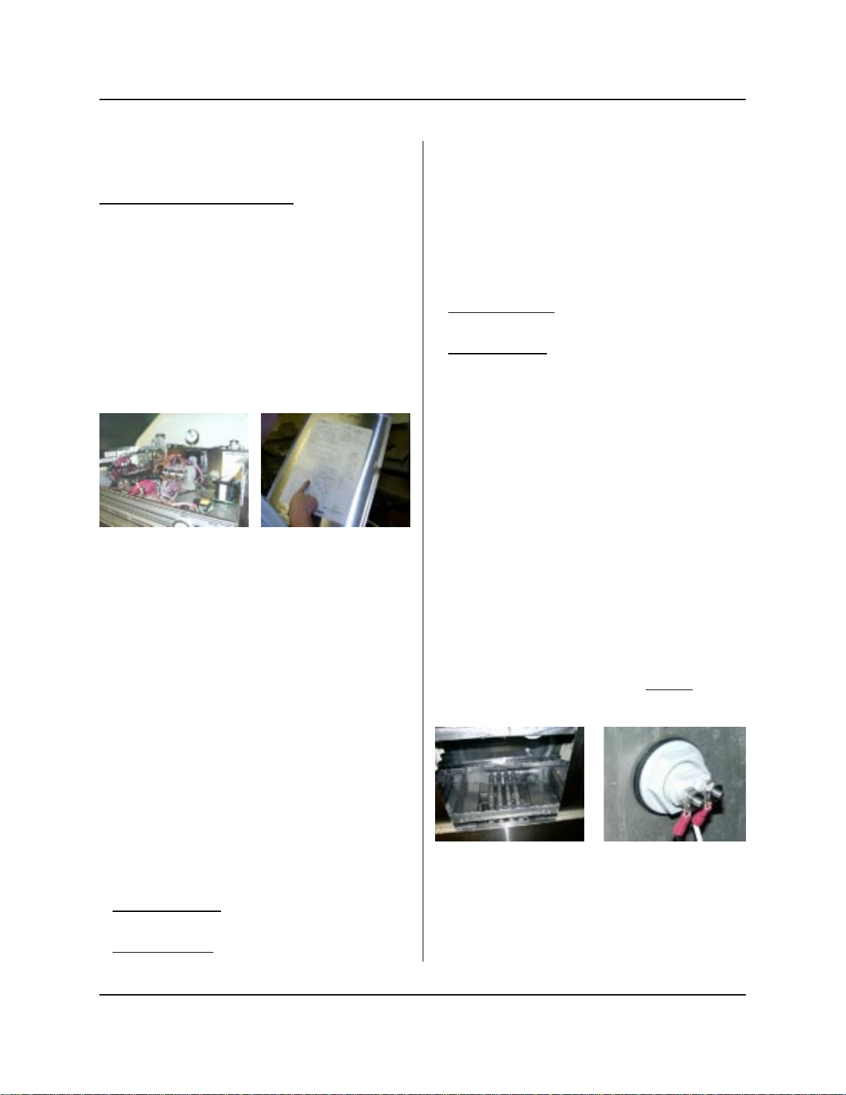
PRE-INSTALLATION
Check all applicable plumbing and electrical codes before installation. This will help to ensure that the system is
installed in safe and suitable manner. A wiring schematic of the dishwasher is useful. This is provided by the
dishwasher manufacturer or may be on the machine itself.
Plan to mount the unit on a nearby wall. Try to keep the unit within three feet from the final rinse line to avoid long
tubing runs. Do not
unit. Mounting the unit on the side, on the back, or on the vents of the dishwasher may cause thermal overload and
damage the performance of the unit.
If you are going to add a sanitizer pump (optional) to a two-product system, then it should be attached to the unit prior
to installation (see page 14).
mount the unit in the direct path of steam. This can short-circuit and permanently damage the
Before beginning the installation, make sure you have the following tools and materials ready...
• Flat and Phillips screwdrivers. One screwdriver needs
to have a long (20 cm) shank to reach the bottom
mounting screw on the dispenser.
• Drill and drill bits.
• 18 gauge wire for power, signals, and probe (check
local codes).
• Wire cutters, wire strippers, and pliers.
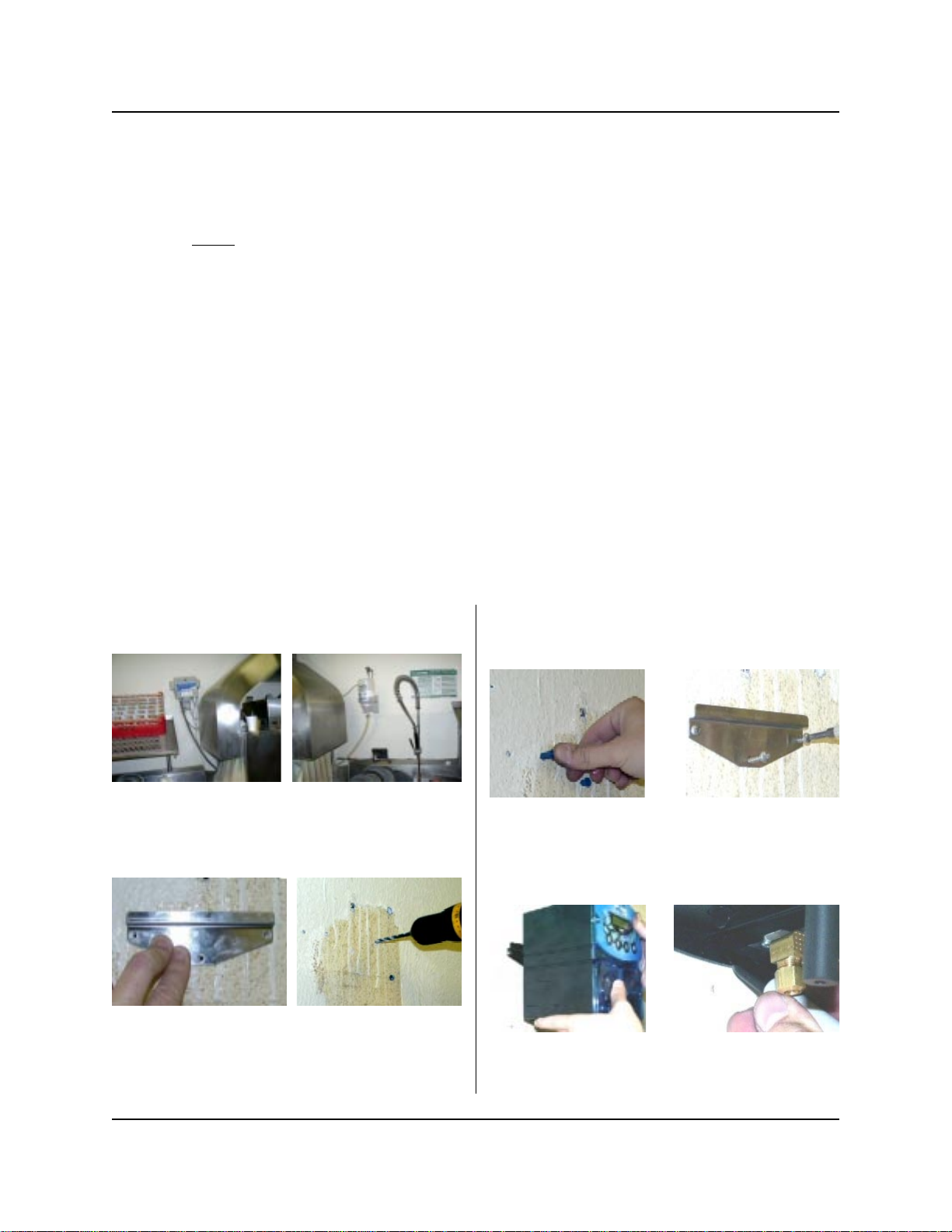
INSTALLATION — MOUNTING
(1) Remove existing dispenser, if any.
(2) Use the mounting bracket to mark where the holes
need to be drilled. Drill the three holes.
• Wire terminal connectors and a crimping tool.
• Voltmeter (or multi-meter).
• Dry wall inserts and mounting screws.
• Electrical tape.
• Titration kit.
• Dispenser accessory kit.
(3) Press in the dry wall anchors and mount the
bracket.
(4) Hang the dispenser and mark where the bottom
hole goes.
(5) Drill last hole and press in final dry wall insert. Do
not install the unit on the wall yet.
Page 4 of 24 0900591 Rev: A (07/04)
INSTALLATION — ELECTRICAL
Review the wiring diagrams on pages 20 - 22 to
familiarize yourself with the wiring connections that
apply to the UniTech model you have.
Important note for pre-wired units:
color coded wires for power, signals, and probe. Be sure
to use the correct wires for the following electrical
connections. The transformer connections in these
models are pre-wired for 230V (as shown in the wiring
diagrams). This must be changed inside the unit
prior to installation for 115V or 208V applications!
European models will always be 230V only!
Make sure that all power is off to the dishmachine. Open
the cover and locate an appropriate source for the wash
pump and rinse pump signals, plus a main power
source (for single transformer units). Consult the wiring
diagram for the dishmachine, if available.
These models have
Main Power
A main power connection only applies to single
transformer systems (typical). Disregard this section for
dual transformer systems.
Connect leads to a 115, 208, or 230 VAC power source
that is “on” when the dishmachine is “on.” This will
provide power for both detergent and rinse however,
UniTech will only pump chemical when electrically
signaled. Whenever possible, use the dishmachine’s
ON/OFF switc h as the main power s ource. Avoid using
the dishmachine’s washpump motor as main power.
Rinse Signal
In addition to running the rinse pump, the rinse power
signal triggers detergent recharge injection if probeless
mode is selected. The rinse signal can also be used to
trigger the detergent initial charge if using probeless/
door mode.
Check the dishwasher for a power source that is active
during the rinse cycle only, for example, the rinse
solenoid or rinse cycle light.
• Single transformer: Connect leads to the rinse signal
source. Signal voltage range is 14 - 240 VAC.
• Dual transformer: Connect leads to the rinse power
source (must be 115, 208, or 230 VAC).
Probe Installation (if required)
Drain the dishmachine if necessary. Install the probe per
the following steps, or replace any existing probe (if
there is one). Use new probe wire in either case.
(1) Install the probe in the wash tank below the water
level. It should be away from incoming water
supplies, near the recirculating pump intake, and 3
to 4 inches from corners, heating elements, or the
bottom of the tank. If an existing mounting hole
cannot be located, cut or punch a 7/8" hole.
(2) Use 18 AWG multi-stranded copper wire for the
probe connection. Avoid running the wire near high
voltage AC lines. Do not route probe wires through
the same conduit as power and signals.
(3) Connect leads to the probe. Ring-type terminals are
recommended (be sure to connect them to the
probe terminals with “backing” nuts to prevent the
probe tips from being pulled out of the probe). The
ring terminals should be secured between
(backing) nuts and outer nuts.
the inner
Detergent Signal
A detergent signal is required to either activate the
detergent probe sensing operation, or to trigger
probeless initial charge. A detergent signal is not
normally required when using probeless/door mode, as
the rinse signal is typically used to trigger initial charge.
Check the dishwasher for a power source that is active
during the wash cycle only, for example, the magnetic
contactor that controls the wash pump motor.
• Single transformer: Connect leads to the detergent
signal source. Signal voltage range is 14 - 240 VAC.
• Dual transformer: Connect leads to the detergent
power source (must be 115, 208, or 230 VAC).
0900591 Rev: A (07/04) Page 5 of 24
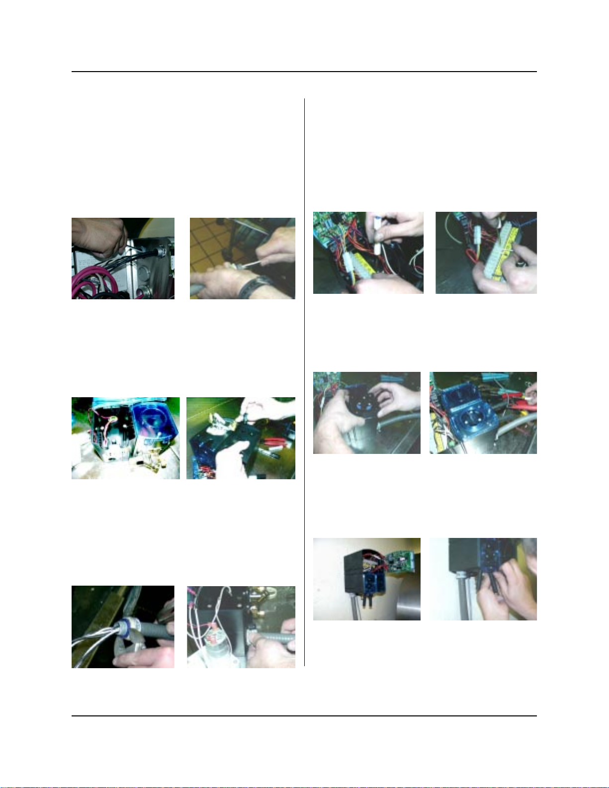
Connecting Power/Signals & Probe to UniTech
Steps 1 - 6 pertain to typical installations, where final
electrical connections must be completed inside the
UniTech dispenser. Disregard steps 1 - 6 for models
that are “pre-wired”.
(1) Ensure that all power sources are turned off before
proceeding with the following steps.
(2) Pull the power and signal wires through the conduit.
Do not route probe wires through the same conduit.
(3) Remove the rinse pump from the left side of the
dispenser to make room. Remove knockout plug for
the conduit by twisting with pliers. Remove
knockout plug for the probe wires. Install wire
grommet for probe wires.
(4) Pull wires through the pump case and into the
control box. Loosen the end of the conduit so that
the male piece can freely rotate. Clearance is tight
in the pump case, and you cannot easily rotate the
conduit nut. Instead, hold the conduit nut with a
wrench and rotate the male piece to tighten.
(5) Disconnect the wiring harnesses to gain easier
access to the wiring terminal strip. The terminal
strip panel can be removed by loosening one screw
(panel is slotted, therefore the screw does not need
to be removed). Slide the panel off the screw and
lift out to access. Strip the wires for power, signal,
and probe (if used) to ¼” bare ends and attach to
the appropriate terminals on the strip. See wiring
diagrams (pages 20 - 22) for further reference.
(6) Re-attach the terminal strip and tighten the screw.
Re-connect all wiring harnesses. Replace rinse
pump and attach faceplate.
(7) When all electrical wiring connections have been
performed, it will be time to hang the dispenser on
the wall. Install the final screw at the bottom of the
dispenser. Use a long shank screwdriver to reach it.
Page 6 of 24 0900591 Rev: A (07/04)
INSTALLATION — PLUMBING
Rinse & Sanitizer Plumbing
The following installation steps apply for rinse and
sanitizer pumps alike.
(1) Install the provided 1/4" tube x 1/8" NPT injection
fitting into the side or bottom of the dishwasher
rinse line between the rinse solenoid valves and the
rinse jets. If necessary, drill a 11/32" hole and tap to
1/8" NPT. Use of a saddle clamp may be desired on
copper rinse line for better support.
(2) Cut a suitable length of 1/4" OD poly tubing and
connect between the discharge (right) side of the
pump’s squeeze tube and the injection fitting.
(3) Cut a suitable length of 1/4" OD poly tubing and
connect between the suction (left) side of the
pump’s squeeze tube and the pickup tube provided.
Be sure to draw tubing through the end of the
pickup tube.
(4) Hand-tighten the compression nuts on both the
injection fitting and pickup tube. Plastic ties can be
used to cinch around the connections where the
poly tubing is inserted into the pump’s squeeze
tube.
Liquid Detergent Plumbing
(1) Install the provided bulkhead fitting through a wall
of the wash tank (above water level). If an existing
mounting hole cannot be located, cut or punch a
7/8" hole.
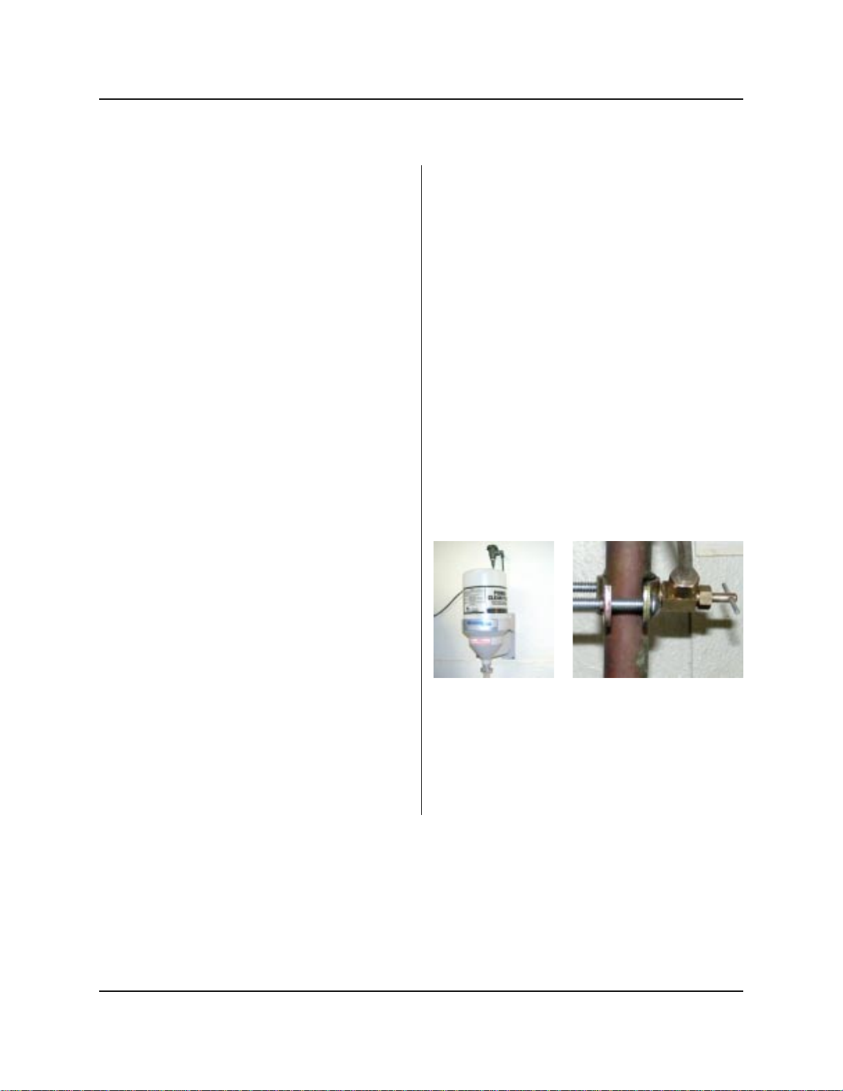
Dry Detergent Plumbing
(1) A powder or solid type feeder (not provided) should
be used for dispensing dry detergent products.
Follow the instructions included with the detergent
feeder for installation, and recommended water
temperature/pressure.
(2) Cut a suitable length of 1/4" OD copper tubing (not
provided) and connect between the input side of the
water solenoid and the water source. Maximum
recommended water temperature is 140°F (60°C).
(3) Cut a suitable length of 1/4" OD copper tubing (not
provided) and connect between the output of water
solenoid to a powder or solid detergent feeder.
(4) Carefully tighten the compression nuts on the water
solenoid — over tightening may cause solenoid to
leak. Tighten connections to the water source and
detergent feeder as needed.
NOTE: If there is an existing dispenser that uses dry
detergent, examine the power bowl. Make sure it is not
clogged and that the spray pressure is sufficient to
dissolve solid/powder products efficiently. Make sure the
water source is hot water. If necessary, tap into a hot
water line for a new source.
(2) Cut a suitable length of 1/4" OD poly tubing and
connect between the discharge (right) side of the
detergent pump’s squeeze tube and the bulkhead
fitting.
(3) Cut a suitable length of 1/4" OD poly tubing and
connect between the suction (left) side of the
detergent pump’s squeeze tube and the pickup
tube provided. Be sure to draw tubing through the
end of the pickup tube.
(4) Hand-tighten the compression nuts on both the
bulkhead fitting and pickup tube. Plastic ties can be
used to cinch around the connections where the
poly tubing is inserted into the pump’s squeeze
tube.
0900591 Rev: A (07/04) Page 7 of 24

OPERATION
BUTTON FUNCTIONS
Detergent — Probe Mode
With the detergent signal “on”, the conductivity probe
senses detergent concentration. When concentration
drops below the setpoint, the control automatically turns
on detergent feed. As the detergent feeds, the control
senses the rate at which the detergent concentration is
approaching the setpoint. The control then begins to
pulse feeds to prevent over-use of chemical. The pulse
feed rate will depend on how fast the setpoint is being
approached.
The detergent alarm will sound if the setpoint is not
reached within the alarm delay time period. The alarm
can be temporarily silenced. A “feed limit” feature allows
you to set the unit to automatically shut off the detergent
feed when the alarm has been activated.
Detergent — Probeless Mode
Controls detergent concentration without a probe, based
on timed detergent feed modes. Initial charge time feeds
detergent to bring the dishmachine to working
concentration when initially filled with water. The initial
charge can be activated by a detergent signal, or by the
rinse signal (of 30 seconds duration, or longer) when
using door mode. The initial charge counter will
increment for each activation.
Recharge time feeds detergent to maintain detergent
concentration as rinse water dilutes the dishmachine.
The recharge is triggered after a specified number of
racks passes through the machine.
Rinse Pump
The rinse pump will operate whenever the rinse signal is
energized. The rinse delay feature will postpone the
activation of the rinse pump until the delay time has
expired. The rinse limit shuts down the rinse pump after
the signal has been present for a selected time. Rinse
delay and rinse limit are functional with door machines
only.
• ENTER: Holding the enter button for 3 seconds
(approx.) switches between run and program modes.
Enter also advances through programming menus.
• SCROLL: The scroll button moves the position of the
cursor in menus where text or number changes are
done. The scroll button will “wrap around” at the end
of a line of characters, meaning that the cursor will
advance to the beginning of the line automatically.
The scroll button toggles between choices in menus
that have selectable settings. The scroll button also
shows the rack count and initial charge count during
normal operation.
• UP (
• DOWN (
): Increases numeric values or advances
upward through available characters. Hold the button
down to rapidly advance. The UP button also acts as
rinse prime during normal operation.
): Decreases numeric values or advances
downward through available characters. Hold the
button down to rapidly advance. The DOWN button
also acts as sanitizer prime during normal operation.
De-lime Mode
During normal operation, hold the SCROLL and DOWN
buttons simultaneously for 1 full second. When “DeLime Mode“ appears on the display, all chemical feed of
the UniTech will be halted. Press the SCROLL and
DOWN buttons again, or cycle main power to the unit, to
exit the de-lime mode. Otherwise, the unit will
automatically exit de-lime mode after 10 minutes.
Alarm Mute
During normal operation, the low detergent alarm
(probe mode) can be silenced by pressing the SCROLL
and UP buttons simultaneously for 1 full second. The
display will show “Alarm Muted” and the audio alarm will
turn off for 5 minutes.
Sanitizer Pump
A menu selection sets the sanitizer pump to operate
with detergent feed, or with rinse feed. The sanitizer
pump will run simultaneously with detergent or rinse,
whether using probe or probeless mode, rinse delay or
rinse limit.
Page 8 of 24 0900591 Rev: A (07/04)
 Loading...