

Knight Equipment UNITECH Installation Manual
UniTech Laundry
Instruction Manual
0900857 Rev: A (06/05) Page 1 of 24
TABLE OF CONTENTS
Specifications .......................................................................................................3
Pre-Installation ......................................................................................................4
Installation
►
Mounting
►
General
..........................................................................................................5
►
Signal Connections
Operation ..............................................................................................................7
Programming ........................................................................................................8
Adding Pumps .................................................................................................... 16
Changing the Circuit Board
►
Procedures
►
Jumper Settings
Parts Diagrams
►
Main Controller
►
800 Satellite
........................................................................................................4
.........................................................................................6
................................................................................................... 17
........................................................................................... 17
............................................................................................. 18
.................................................................................................. 20
Pump Layout Diagram ........................................................................................ 21
Wiring Diagram ...................................................................................................22
Declaration of Conformity ................................................................................... 23
Warranty Information .......................................................................................... 24
Knight Locations ................................................................................................. 24
CAUTION: Wear protective clothing and eyewear when dispensing chemicals or
other materials. Observe safety handling instructions (MSDS) of chemical mfrs.
CAUTION: To avoid severe or fatal shock, always disconnect main power when
servicing the unit.
CAUTION: When installing any equipment, ensure that all national and local
safety, electrical, and plumbing codes are met.
Page 2 of 24 0900857 Rev: A (06/05)
SPECIFICATIONS
Parameters Default Value Range
Pass Code 0000 0 – 9, A – Z
Pump Flow Rates 0 0-99.9 Oz, 999.ml
System Mode Signal Signal, Drain, Relay
Formula # 1 1 to 20
Load Count Pump 2 1 to 8
Load Counter 0 0 – 65536
Units of Measure US US, Metric, Imperial
Pump Delay Units SEC SEC, MIN
Wash Signal Lockout Disabled Disabled, Enabled
AFS Select Disabled Disabled, Enabled
System Lockout Time 0 0-100 min
AFS Mode Micro Micro, Chart
AFS Micro Time Div 1 1, 2, 5
Flush Mode Disabled Disabled, Enabled
Flush Time 0 0-100 sec
Drain Signal Polarity Normal Normal, Inverted
Washer Signal Qualify Time 1 1-100 sec
Calibrate Mode Time Time, Volume
Flush Flow Check Delay 5 0-100 sec
Formula Run Times/V olumes 0 0-255 sec, 0-999 ml, 0-99.9 oz
Formula Delay Times 0 0-255 sec or min
Formula Names Formula ## Alpha-numeric range
Pass code does not change when clearing all programmed settings
The load counter has its own menu to allow resetting back to zero
SAFETY SYMBOL EXPLANATIONS
Listed below are explanations of the safety symbols that appear either on the unit, in the instruction manual, or both.
Please familiarize yourself with the meaning of each symbol.
GENERAL CAUTION: This symbol indicates a general safety caution.
SHOCK HAZARD: This symbol indicates that hazardous voltages are inside the
enclosure.
READ MANUAL: This symbol indicates to read the manual for important
instructions and procedures related to safety.
0900857 Rev: A (06/05) Page 3 of 24
PRE-INSTALLATION
(1) Check all applicable plumbing and electrical codes before installation. This will help to ensure that the system is
installed in safe and suitable manner.
(2) Get a wiring schematic of the washmachine (provided by the machine mfr or may be on the machine itself).
(3) Check to make sure that all functions of the washmachine are operating properly. Including; card reader or timer,
water solenoids, flush down valves, water level switch, machine motor, and drain valve.
(4) Check the proposed location for a 115, 208, or 230 VAC power source.
(5) Check voltage of all washmachine supply signals that will be used. Measure voltage between supply signal and
signal common with a voltmeter. Do not
(6) Measure the distance from chemical supply containers to pump housing, and from pump housing to injection
point inside washmachine.
check signal voltage between supply signal and case (earth) ground.
Before beginning the installation, make sure you have the following tools and materials ready...
• Flat and Phillips screwdrivers. One screwdriver needs
to have a long (20 cm) shank to reach the bottom
mounting screw on the dispenser.
• Drill and drill bits.
• Suitable wire for main power and signals (check local
codes).
• Wire cutters, wire strippers, and pliers.
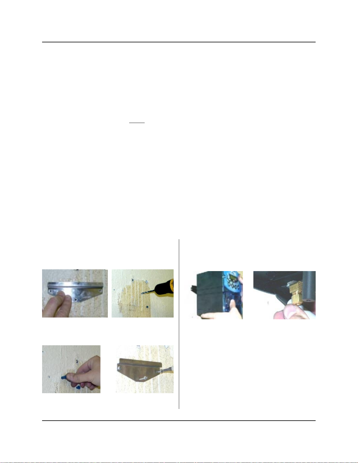
INSTALLATION — MOUNTING
(1) Remove existing dispenser, if any.
(2) Use the mounting bracket to mark where the holes
need to be drilled. Drill the three holes.
(3) Press in the dry wall anchors and mount the
bracket.
• Wire terminal connectors and a crimping tool.
• Voltmeter (or multi-meter).
• Dry wall inserts and mounting screws.
• Electrical tape.
• Chemical test kit.
• Dispenser accessory kit.
(4) Hang the dispenser and mark where the bottom
hole goes. For UniTech systems with more than
two pumps, mark the locations of the other
mounting holes.
(5) Drill remaining holes and press in final dry wall
inserts. Do not install the unit on the wall yet.
(6) If you are using an MFM remote control, mount it to
the front of the washer where operators can easily
access it. Secure it to the washer using provided
mounting screws or Dual-Lock fastening strips (be
sure to first clean the mounting surface as the
adhesive will not stick to a dirty surface).
NOTE: Systems shipped from the factory will already
have the MFM cable connected inside the control box. If
adding an MFM to an existing system, connect the cable
per the wiring diagram on page 22.
Page 4 of 24 0900857 Rev: A (06/05)
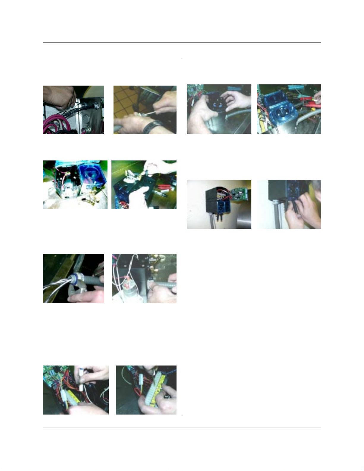
INSTALLATION — GENERAL
Ensure that all power sources are turned off before
proceeding with the following steps.
(1) Pull the power wires through the conduit.
(2) Remove the pump from the left side of the
dispenser to make room. Remove knockout plug for
the conduit by twisting with pliers.
(3) Pull wires through the pump case and into the
control box. Loosen the end of the conduit so that
the male piece can freely rotate. Clearance is tight
in the pump case, and you cannot easily rotate the
conduit nut. Instead, hold the conduit nut with a
wrench and rotate the male piece to tighten.
(4) Disconnect the wiring harnesses to gain easier
access to the wiring terminal strip. The terminal
strip panel can be removed by loosening one screw
(panel is slotted, the screw does not need to be
removed). Slide the panel off the screw and lift out
to access. Strip the power wires to ¼” bare ends
and attach to the appropriate terminals on the strip.
See wiring diagram (page 22) for further reference.
(5) Re-attach the terminal strip and tighten the screw.
Re-connect all wiring harnesses. Replace pump
and attach faceplate.
(6) Hang the dispenser on the wall and install the final
screw at the bottom of the dispenser. Use a long
shank screwdriver to reach it. For UniTech systems
with more than two pumps, install the remaining
mounting screws.
(7) For each pump, cut the suction tube to length and
insert one end into the appropriate supply container
using PVC pipe as a support. Insert other end of
suction tube into the left (input) side of the pump’s
squeeze tube.
(8) For each pump, cut the discharge tube to length
and insert one end into the right (output) side of the
pump’s squeeze tube. Form an anti-siphon loop
(pointing “down“) with the other end of discharge
tube and insert into the supply pocket of the
machine.
NOTE: If using a flush manifold, the output side of the
pump’s squeeze tube will connect to the checkvalves on
the manifold.
Powering Up
Upon power up, the display will sequence through all
devices that are recognized, such as the satellite
pumps, SIB, and MFM controller. If the display shows a
pump that is not the correct size (for example: if an 800
pump is used, but the display shows that it’s a 500)
contact Knight for assistance.
0900857 Rev: A (06/05) Page 5 of 24
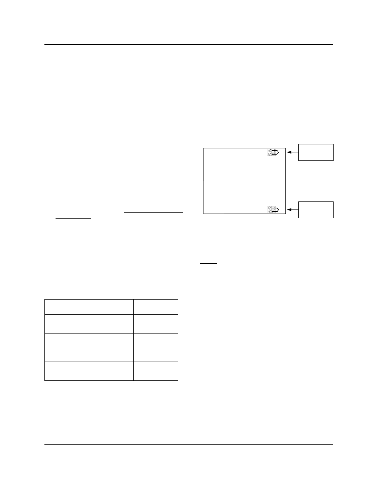
INSTALLATION — SIGNALS / SIB
The SIB is a signal interface module that receives
supply signals from the washer, then communicates
with the dispenser to run the pumps. The low voltage
cable connects the module to the pump system without
requiring conduit.
NOTE: Systems shipped from the factory will already
have the SIB properly connected. If a system in the field
later has an MFM added, then the SIB will need to be
connected directly to the MFM instead of the pump unit.
See the wiring diagram on page 22 for details.
(1) Mount the module using the provided Dual Lock
adhesive strip. The module can be mounted inside
the washer’s controls, along side the washer’s
controls, or any other convenient location.
(2) Connect the supply signals to the SIB per wire
colors on the SIB label. If using Drain Mode, only
one signal is required (pump #1).
(3) If you have one signal common (typical) connect
the common to “COM A” on the SIB. If you have
two signal commons, you will need to remove a
resistor inside the SIB before connecting the
common wires! See the following details.
Splitting signal commons:
(1) Remove the screws from the bottom of the SIB to
open the module.
(2) Loc ate the resi stors on the r ight sid e of the modu le
(each resistor has a single black band).
(3) Cut and remove the resistor that will “split” the
commons between the desired pumps. Be sure to
remove only one resistor.
CUT RESISTOR
R19 1—2 3—8 (and AFS)
R20 1—3 4—8 (and AFS)
R17 1—4 5—8 (and AFS)
R15 1—5 6—8 (and AFS)
R16 1—6 7—8 (and AFS)
R18 1—7 8 (and AFS)
R21 1—8 AFS
TO USE COM A
FOR PUMPS
AND COM B
FOR PUMPS
Low voltage signal filter
The SIB signal filtering capability can help prevent
unwanted injections caused by stray signals or “bleed“
voltages. Typically you will have only one signal
common, however, if using “split commons”, each
common can be independently set to filter signals.
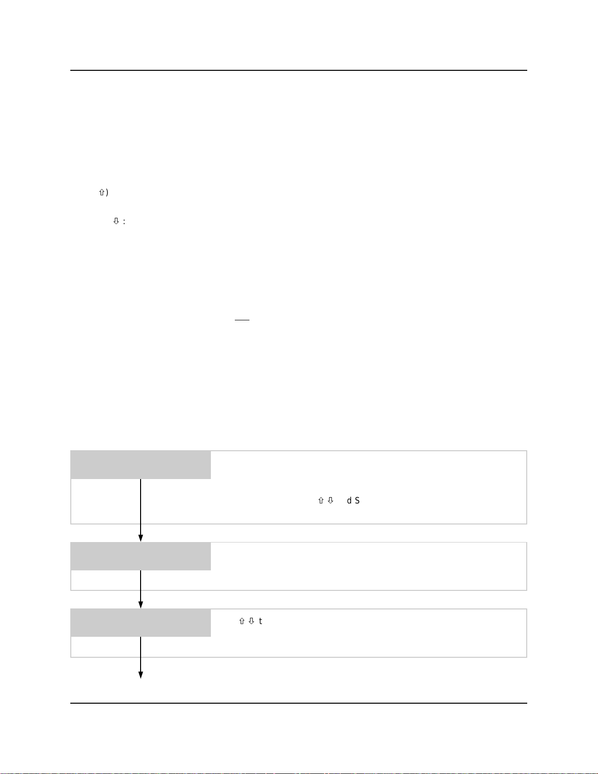
The signal filter is activated by removing a jumper wire
inside the SIB. There is one jumper wire for common A
and one for common B (if required). The diagram below
shows the location of the jumper wires inside the SIB.
Jumper wire for
common “A”
signal filter
Jumper wire for
common “B”
signal filter
• When the jumper wire is removed, the signal input
range is 70 – 240 volts.
• With the jumper wire in place (normal) the signal input
range is 24 – 240 volts.
• Do not connect any signal wires or common wires to
the terminals where the jumper wires go.
Follow the steps below to activate the signal filter. If you
later need to setup the SIB for normal signal range,
simply replace the jumper wires.
(1) Remove all screws from the bottom of the SIB to
open the module.
(2) To filter signals that use common A, remove the
jumper wire from the terminals in the upper left
corner of the circuit board.
(3) To filter signals that use common B (if required),
remove the jumper wire from the terminals in the
lower left corner of the circuit board.
(4) Close the module and replace screws when
finished.
(4) Close the module and replace the screws when
finished.
Page 6 of 24 0900857 Rev: A (06/05)

OPERATION
The UniTech laundry system has three operating modes for maximum versatility with all types of washing machinery,
and allowing you to choose the operation best suited for your application.
Signal Mode
The system is capable of up to 20 user selectable formulas with each formula having unique run times and delay
times for each pump. The base unit holds a maximum of 8 formulas (and also if using the formula selector). The
maximum of 20 formulas requires use of the MFM hand-held controller. Signals from the washer trigger the pumps,
then the UniTech takes control to count down delay times and run times with up to 3 individual “levels” (explained
below) for each pump. The machine operator, will select the formula using or buttons to choose the appropriate
wash formula.
Programming "levels" allows a pump to inject different amounts of chemical for multiple signals to the same pump
during a formula. For example, pump 1 could inject 8 ounces of chemical on its first signal, then later inject 12 ounces
of chemical on its second signal. Up to three levels are available for any pump on any formula, except for the load
count pump. Only 1 level can be programmed for the load count pump (and any other pump that may be signaled
simultaneously with the load count pump's signal). The level feature can also be used to “skip over” an injection.
Simply do not program any volume or delay time for that level.
One-to-one pump signal mode:
to be present for at least as long as the signal qualify time to be recognized. The second signal to the pump during
the formula will activate level 2. The third signal to the pump during the formula will activate level 3. Any further
signals will be disregarded once level 3 has been activated. The load count pump signal must be received to reset
levels in preparation for the next formula.
Assigned pump signal mode:
SIB) will trigger the chemical injection. For example, pump 1 input on the SIB becomes “signal 1” and can be
assigned to whatever pumps you wish to activate with this signal. Pump 2 input on the SIB becomes “signal 2”, and
so on. Incoming signals should be received by the UniTech in order from lowest number to highest number. This type
of operation allows certain types of washer signals to be used more effectively to trigger chemical injections.
When a formula begins the first signal to a pump will activate level 1. The signal has
Each pump/formula/level combination has a signal assignment for which signal (to the
Drain Mode
This mode is similar to signal mode but requires only one signal source from the washer and works by counting the
number of drains during a wash cycle. When programming UniTech for drain mode, each chemical pump is assigned
a specific drain occurrence to inject product on. This feature only affects how the pumps are triggered – all other
functions such as pump run times, delay times, and flush mode, will still operate normally.
During a wash formula, each drain signal is counted and the pumps inject chemical according to the drain number
they are assigned. Drain mode is similar to signal mode, in that the pumps are programmed with run times (and delay
times if necessary) and the flush mode works the same way it does in signal mode. Be sure to set the load count
pump as the last pump to inject during a formula, and program a drain assignment for the load count pump on every
formula used. If necessary, you can choose an unused pump number to be the load count pump.
The “multiple level” feature works slightly different in drain mode, because of the way drain mode counts the number
of signals to pump #1 input. If a second injection level is required, it should be programmed to inject on a later drain
number (occurrence) than the first level for that pump.
• During a formula, when pumps are idle, the display will show the current drain count and the formula name.
• Auto Formula Select is functional in drain mode, but not typically used (chart-type AFS is not recommended).
• Auto Formula Select (if used) resets drain count.
Relay Mode
This type of operation can be used with a microprocessor controlled washer. When set to relay mode, the UniTech
system will run its pumps as long as their respective signals are present. There is a slight delay of a few seconds
before the pump starts and stops running. The on and off delay are about equal, so there is no real need to adjust the
signal duration for accurate dosing. To accomplish this, the system “by-passes” its run time and delay time
capabilities for the chemical pumps, however flush mode still works the same way. Choosing a load count pump is
optional in relay mode — load counts are tallied as a cumulative number and viewed in the typical manner.
0900857 Rev: A (06/05) Page 7 of 24
BUTTON FUNCTION REFERENCE
• ENTER: Holding the enter button for 3 seconds (approx.) switches between run and program modes. Enter also
advances through programming menus.
• SCROLL: The scroll button moves the position of the cursor in menus where text or number changes are done and
toggles between choices in menus that have selectable settings. By pressing repeatedly, the cursor will “wrap
around” at the end of a line of characters (advance to the beginning of the line automatically). The scroll button is
also used to show load counts during normal operation. Press the button repeatedly to see load counts for
individual formulas, then will show the total cumulative load count.
• UP (
): Increases numeric values or advances upward through available characters. Hold the button down to
rapidly advance. The UP button also chooses the formula during normal operation.
• DOWN (
to rapidly advance. The DOWN button also chooses the formula during normal operation.
): Decreases numeric values or advances downward through available characters. Hold the button down
PROGRAMMING
You may find it helpful to read through the programming instructions before getting started. This will better familiarize
you with the operation of the UniTech, and will make the actual programming go much quicker.
Important Notes
• Be sure to clear all settings in base unit and MFM (if so equipped) before programming.
• If using an MFM, it is recommended to do all programming at the MFM keypad, rather than the base unit.
• If you wish to return to normal operating mode at any point during programming, hold down the ENTER button for 3
seconds to exit the programming mode.
• While programming, if no buttons are pressed for approximately 2 minutes, UniTech will automatically return to
normal operating mode.
When you’re ready to get started, hold down the ENTER button for about 3 seconds to go into the programming
mode. Release the button when you see the access code prompt below...
ENTER ACCESS
0000 CODE:
All new systems are shipped from the factory with the access code set at
0000. If the system is new, press ENTER to continue.
If the access code has been changed from the default of 0000 (explained
later in this manual) use / and SCROLL to type in your code, then press
ENTER to continue.
SELECT LANGUAGE:
ENGLISH
PRIME PUMP 2
SCROLL = START
Continue on next page
Page 8 of 24 0900857 Rev: A (06/05)
If you wish to change the menu language, press SCROLL to advance
through the available choices until your desired language name is shown on
the display. Press ENTER to continue.
Use / to choose the pump number (or flush solenoid if used) that you
wish to prime, then use SCROLL to turn the pump on or off. Repeat as
needed for other pumps. When finished, press ENTER to continue.
 Loading...