

Knight Equipment SINK MATE Installation Manual
INSTALLATION
6,1.0$7(
,16758&7,210$18$/
(1) Choose a mounting location within easy reach of the sink. Make sure
the Sink Mate is at least 12 inches above the chemical supply
container(s).
(2) Mount the unit using the wall anchors provided.
(3) Connect the water supply to the swivel garden hose connection.
Optimum water pressure is 30 - 40 PSI (water pressure over 40 PSI
may cause splash-out on Aire-Gap equipped units). It may be
possible to use a saddle-clamp to plumb directly into the water line.
Another possible connection is the Knight Faucet Plus Sink Adapter
Kit (P/N 7114100). Contact your local Knight representative for
details.
(4) For 1 product units: Route the outgoing 3/4" vinyl tube up through the bottom of the unit and connect to the
bottom of the mixing valve assembly. Flex-Gap equipped units have a “flow restrictor” inside the 3/4” tube —
connect the tube so that the end with the flow restrictor is closest to the valve.
For 2 product units:
have one nearby sink tub, and the other is farther away). Flex-Gap equipped units have a “flow restrictor” inside
both ends of the 3/4” tube. Cut the tube into the 2 lengths required for your installation, making sure that the end
with the flow restrictor (if used) will be closest to the valve. Route the tubes up through the bottom of the unit and
connect to the bottom of the mixing valve assemblies.
(5) Route the discharge end of the 3/4” vinyl tube(s) to the sink, securing the tube(s) to the wall with the provided tie
wraps (they have an “eyelet” for mounting hardware). Cut off any excess tube length not needed.
(6) For 1 product units:
bottom of chemical container.
For 2 product units:
the tube into the 2 lengths required for your installation — the tubes must reach from metering tips to bottom of
chemical containers.
A long 3/4” output hose is included so you can cut into needed lengths (many installations
Cut the 3/8" suction tube to a suitable length — the tube must reach from metering tip to
A long 3/8” suction tube is included with the unit. so you can cut into needed lengths. Cut
IMPORTANT NOTE:
If proportioner is connected to a janitor’s sink
an atmospheric vacuum breaker, a special
with
connection kit is required by A.S.S.E.
specification 1055. Failure to use this kit, or
equivalent connection means, will invalidate
the A.S.S.E. and I.A.P.M.O. (UPC)
certification. Specify P/N 7600187 when
ordering the kit.
(7) Insert the appropriate metering tip into the valve(s) — see the following page for tip selection.
(8) Route the suction tube(s) up through the bottom of the unit and slide the tube(s) over the metering tip. Secure in
place with a tie wrap.
(9) Slide a ceramic weight onto the pickup end of the suction tube, then insert a footvalve into the tube.
(10)Drop the suction tube(s) into the chemical container(s), ensuring that the ceramic weight pulls the footvalve(s)
down to the bottom of the container(s).
OPERATION
Turn the “T” handle (on the ball valve) counter-clockwise to open the valve, and clockwise to close it. Check all
connections for leaks and verify that chemical is being pulled up suction line. Make any necessary adjustments and
the unit is then ready to go!
0900512 Rev: D (02/02) Page 1 of 4
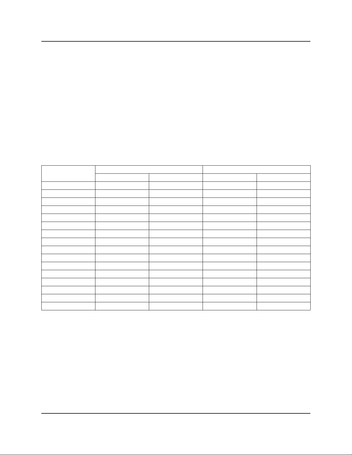
METERING TIP SELECTION
The chart below is based upon the chemical viscosity of water (CPS = 1.0) and should only be used as a guide.
Actual ratios and flow rates may vary due to product viscosity, flow pressure, and tubing distance. To easily calculate
the actual ounces per gallon for a specific product:
(1) Fill graduated cylinder or spray bottle (that has ounce markings) with product.
(2) Install metering tip closest to desired ounces per gallon from chart.
(3) Drop chemical pick-up tube into the container holding the product.
(4) Activate valve until chemical line is primed up to the metering tip.
(5) Note how many ounces of product are in the container.
(6) Activate valve again, filling a one gallon jug with water/product mix.
(7) Note how many ounces of product were used — this is your actual ounce per gallon ratio.
TIP COLOR
NO INSERT 21 5.1:1 25 4.3:1
WHITE 20 5.4:1 20 5.4:1
YELLOW 18 6.1:1 18 6.1:1
PINK 16 7.0:1 16 7.0:1
GREEN 12 10:1 12 12:1
BLACK 10 12:1 10 15:1
BROWN 7 17:1 7 20:1
GRAY 5 25:1 5 31:1
BLUE 4 31:1 4 42:1
RED 3 42:1 3 63:1
PEACH 2 63:1 2 72:1
LT BLUE 1.5 84:1 1.5 101:1
PURPLE 1 127:1 1 127:1
LT GREEN 0.75 170:1 0.75 170:1
ORANGE 0.50 255:1 0.50 255:1
LT BROWN 0.25 511:1 0.25 511:1
AIRE-GAP (3 GPM)
OZ/GAL
RATIO
FLEX-GAP (4 GPM)
OZ/GAL
RATIO
Page 2 of 4 0900512 Rev: D (02/02)
 Loading...