


Knight-Trak II
System Programming Manual
0901002 Rev: F (05/01) |
Page 1 of 34 |

7$%/( 2) &217(176 |
|
Menu Map ............................................................................................................. |
3 |
Keypad Diagram ................................................................................................... |
4 |
Keypad Descriptions............................................................................................. |
5 |
User Display Descriptions..................................................................................... |
6 |
Getting Started / Access Codes............................................................................ |
7 |
Memory Functions ................................................................................................ |
8 |
Setup Routines ................................................................................................... |
10 |
Report Setup Routines ....................................................................................... |
16 |
Maintenance Schedule ....................................................................................... |
21 |
Programming Routines ....................................................................................... |
22 |
Printing Functions ............................................................................................... |
26 |
Pump Test Routines ........................................................................................... |
27 |
Diagnostic Routines............................................................................................ |
28 |
WinReporter Network Diagram........................................................................... |
29 |
Troubleshooting .................................................................................................. |
30 |
67$57 83 352&('85(6 |
|
Check each of the following before connecting power: |
|
(1)Check the voltage-select switch on the POB circuit board located inside the dispenser. Make sure that the voltage to be applied to the dispenser matches the voltage of the POB circuit board. Also make sure the voltage of the pump motors matches voltage to the dispensers. 120 VAC motors have black wires, 240 VAC motors have red wires.
(2)Connect the voltage wires to the input terminals on the POB board. Make sure that no strands of wire are showing.
(3)If your are going to MULTI-LINK several POB boards, make sure that you assign a different ID number to each board PRIOR to connecting the Multi-Link wires.
(4)Make sure that the SIB (Signal Input Board) is properly connected to the LFP. Black, red, and brown wire from the SIB wires marked “SIB” connect to the black, red, and brown terminals inside the LFP. An uninsulated “drain” wire is connected to the BLACK wire. Use a shielded cable APPROVED BY KNIGHT INC.
(5)Connect the LFP to the POB.
(6)If you are using an LMIB (Laundry Management Input Board) to track hot and cold water data and door interlock signals, connect the black, red, and brown wires from the LMIB wires marked LMIB to the black, red, and brown wires on the SIB marked LMIB. If you aren’t using an LMIB, individually tape off the wires on the SIB marked LMIB.
(7)Apply power to the POB.
(8)Always clear dispenser memory before entering new setup program.
(9)If the LFP displays “PTM-6000 not responding/check connections” while connected to an RM-6000, unplug the RM-6000 from the LFP for 10 seconds, then re-connect.
Page 2 of 34 |
0901002 Rev: F (05/01) |

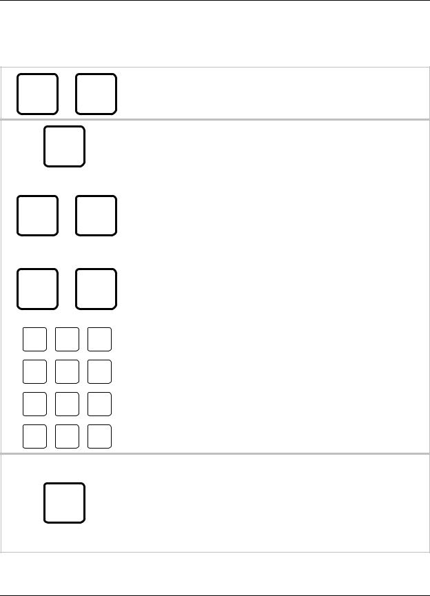
0(18 0$3
1 *** DISPENSER ***
MEMORY FUNCTIONS
∙Clear pump volumes and delay times
∙Clear sum/cycle report memory
∙Clear load counter
∙Clear setup information
∙Load setup file
2 |
*** |
DISPENSER |
*** |
∙ Change ID and main access code |
|
SETUP ROUTINES |
|
∙ Set date and time |
|
|
|
|
|
∙ Select unit of measure |
|
|
|
|
|
|
|
|
|
∙ Setup auto formula select and auto formual reset |
|
|
|
|
∙ Select load count pump and door signal |
|
|
|
|
∙ Set bleach defeat |
|
|
|
|
∙ Set delay time units/set signal lockout |
|
|
|
|
∙ Setup flush mode |
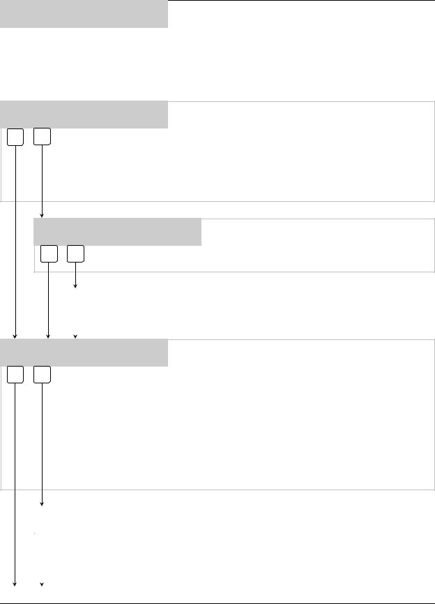
3 |
*** |
DISPENSER |
*** |
∙ Change user access code |
REPORT SETUP ROUTINES |
∙ Setup report name and display features |
|||
∙ Change chemical names and costs ∙ Change formula names and weights ∙ Set shift times and operating zone
∙ Set washer capacity and water flow rates ∙ Setup cycle time information
∙ Set signal qualifying time
4 *** DISPENSER ***
MAINTENANCE SCHEDULE
5 *** DISPENSER ***
PROGRAMMING ROUTINES
∙Date dispenser installed
∙Date tubes last changed
∙Date tubes last lubed
∙Calibrate pumps
∙Prime pumps
∙Set pump flow rates
∙Program pumps
∙Set delay times
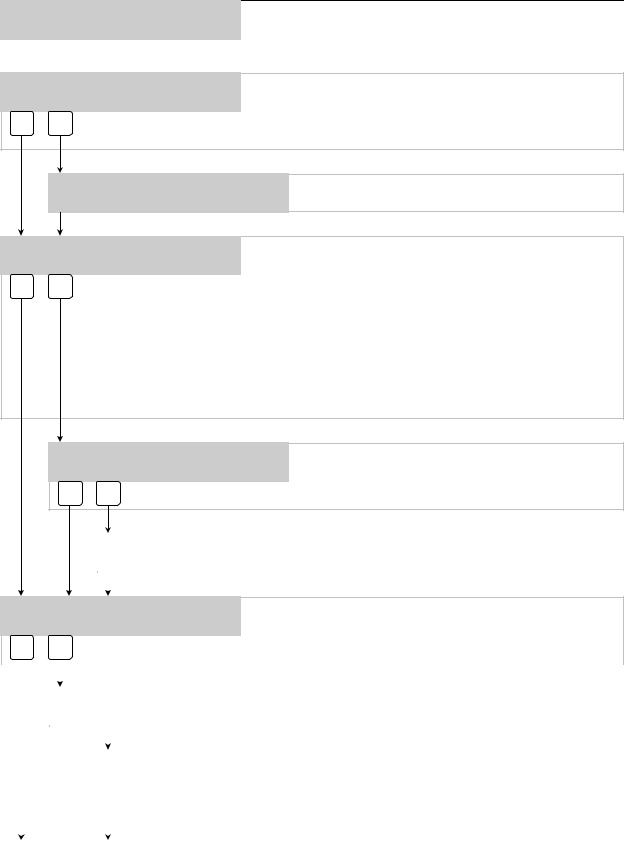
6 |
*** |
DISPENSER |
*** |
∙ Print reports on-site |
PRINTING FUNCTIONS |
∙ Save files to RM-6000 |
|||
|
|
|
|
∙ Simulate signals to pumps |
|
|
|
|
|
7 |
*** |
DISPENSER |
*** |
|
PUMP TEST ROUTINES |
∙ Prime pumps |
|||
|
|
|
|
∙ Test SIB/LMIB signal inputs |
|
|
|
|
|
8 |
*** |
DISPENSER |
*** |
|
DIAGNOSTIC ROUTINES |
∙ Perform SIB noise test |
|||
|
|
|
|
|
0901002 Rev: F (05/01) |
Page 3 of 34 |

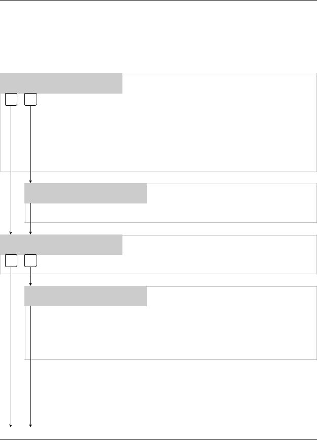
/)3 .(<3$' ',$*5$0
FORMULA NUMBER |
|
PROGRAMMING |
DISPLAY |
|
DISPLAY |
|
|
|
FORMULA 01
DATE 02/05 TIME 10:54:20
0 1
|
|
|
|
|
ALPHANUMERIC |
|
PROGRAMMING |
||
KEYPAD |
|
KEYPAD |
||
|
|
|
|
|
Page 4 of 34 |
0901002 Rev: F (05/01) |
/)3 .(<3$' '(6&5,37,216
The LFP has been designed “USER FRIENDLY“. The only two (2) keys you need to know are the MENU Ø and ENTER. Pressing either key will advance you through the screens. Read the screens and respond with one of the buttons below.
)2508/$ )2508/$
×Ø
0(18 0(18
The MENU (DOWN) and MENU (UP) buttons allows you to move down and up through the menu selections and pick what you want to do. Operators can use them to select formulas as well.
% # |
The ENTER key acknowledges input data and logs it into |
||
memory. It also takes you into a menu for programming. |
|||
|
|
||
|
|
|
|
|
|
The YES and NO keys allow you to pick whether you want to do |
|
|
|
something or not. Additionally, the YES key doubles as a |
|
12 |
<(6 |
BLEACH DEFEAT key, defeating the bleach pump by keeping it |
|
from operating when the “next” bleach signal is received. The NO |
|||
|
|
||
|
|
key doubles as a ALARM MUTE key, which will temporarily shut |
|
|
|
alarms off (due to flush errors, low levels, etc.). |
|
|
|
|
|
Õ |
Ö |
The SCROLL keys allow you to move through a particular menu |
|
screen, and pick one of several items to change (like characters |
|||
6&52// |
6&52// |
||
on a screen, etc). |
|||
|
|
||
|
|
|
|
$ % & |
' ( ) * + , |
|
|
n |
o |
p |
- . / |
0 1 2 |
3 4 5 |
q |
r |
s |
6 7 8 |
9 : ; |
< = |
t |
u |
v |
/2$' |
63$&( |
35,0( |
|
|
|
&2817 |
m |
&$/ |
The alphanumeric keys allow you to input numbers and letters. By repeatedly pressing any key, any of the letter characters (as well as the numeric character) can be entered into the menu selection you are working on. The PRIME/CAL key (lower right corner) can be used to switch units of measure between ounces and gallons when in U.S. units, or between milliliters and liters when in metric units, when auto-calibrating or manually setting flow rate (only). Its also used for priming/calibrating functions. The LOAD COUNT key (lower left corner) shows how many times the load count pump was signaled.
The RESET key performs a number of functions. From any main menu selection, pressing the RESET key LOCKS YOU OUT and returns the screen to the main display. From any screen within a
#$% main menu that allows you to adjust something (i.e. setting a flow rate), pressing the RESET key takes you back to that main menu selection. Subsequently, RESET can be used to halt pump operation; as desired or in an emergency situation.
0901002 Rev: F (05/01) |
Page 5 of 34 |

86(5 ',63/$< '(6&5,37,216
KNIGHT-TRAK II
DATA MANAGEMENT SYSTEM When the LFP is powered up, the display will initially show the image at the left. After a few seconds, the display will change to
one of the example formats shown below.
FORMULA 01
DATE 02/05 TIME 10:54:20 The “main display” screen shows the current formula selected (by name). The date and time are also shown unless load weight
display has been selected...
FORMULA 01
ENTER LOAD WEIGHT 000 LB
..if load weight display has been selected, the programmed load weight for the current formula will be shown. Operators can override the displayed weight and input the actual weight using the number keys, then pressing ENTER (before the formula begins).
Once the formula begins, the load weight is “locked in” and will be used for data-tracking purposes. See menu #3 for more details on programming load weights and choosing the load weight display.
FORMULA 01
\ PUMP-01 L1 000.0 OZS
When there is pump activity, the display will show a count-down of the pump run time, or the pump volume. The letter “L” (with number following) represents the formula “level” being injected.
When the pump is finished, the display will return to its previous appearance. See menu #3 for details on choosing time or volume display for pump activity.
OUT OF OPERATING ZONE
DATE 02/05 TIME 10:54:20 This display indicates that the system is unavailable for dispensing chemical. See menu #3 for more details, and setting
the operating zone.
Page 6 of 34 |
0901002 Rev: F (05/01) |

*(77,1* 67$57('
Knight Track II programming is done through the use of menu selections. Any menu can be entered by pressing the ENTER button, or exited by pressing RESET (or in some cases MENU Ø or ×). Its that simple! Each of the main menu headings give an idea of what information can be found, entered, or changed. Within each main menu selection are several screen “prompts” that walk you through the complete programming process step-by-step.
Below is an example of the main display when you are not in the programming menus. The main display is more commonly referred to as the default display, and appears when the system is in normal operating mode.
FORMULA 01 |
|
The default display shows the present formula name on the top |
|
DATE 05/11 |
TIME 14:32:54 |
||
line. The bottom line of the display will alternate between date/ |
|||
|
|
||
|
|
time and the message ENTER USER PASSWORD. |
|
|
|
The “user password” should not be confused with systems access |
|
|
|
codes. User passwords allow multiple persons to operate the |
|
|
|
system for dispensing chemicals, whereas the access codes |
|
|
|
allow entry into the menus for programming, or report printing. |
|
|
|
From the default display, you must enter the main access code |
|
|
|
(following) to begin programming. |
|
|
|
|
$&&(66 &2'(6
The Knight Track II system has two access codes for protection:
∙The "main" access code, allows entry into ALL of the menus and functions of the system.
∙The "user" access code allows entry into the printing functions menu ONLY, without the ability of changing programmed information.
Systems are shipped from the factory with both access codes set to zero. Only a person with the "main" access code can change the "user" access code. (changing codes is explained later in this manual). If desired the two access codes can be the same, however the user will then have access to ALL of the functions of the system, including the ability of changing programmed information.
72 352*5$0 ',63(16(5 35(66 ´(17(5µ
ENTER ACCESS CODE
THEN PRESS ENTER
,03257$17 127(6
From the default display shown above, press the ENTER button. The screen at left should appear. If the screen at left does not appear, wait 2 seconds, press RESET, then press ENTER.
When you see the screen at left, type in the access code and press ENTER. Remember, for a new system, the access code will be zero (until you change it later).
Follow the programming steps for each section, starting on the next page.
∙Leading zeroes on main access code, user access code, and user passwords, are not required to be entered. For example, a user password of “010” can be typed in as “10”, then press ENTER.
∙Its strongly recommended to clear pump volumes, sum/cycle report, and batch count, then loading factory defaults prior to initial programming of formulas. See MEMORY FUNCTIONS [menu 1] for details.
∙Its recommended to print the setup report and access report each time they’re changed. See PRINTING FUNCTIONS [menu 6] for details.
∙If at any time you get lost in the programming and are not sure what to do, press the RESET button until the section menu heading appears, then proceed.
0901002 Rev: F (05/01) |
Page 7 of 34 |
1 *** DISPENSER ***
MEMORY FUNCTIONS
∙Clear pump volumes and delay times
∙Clear sum/cycle report memory
∙Clear load counter
∙Clear setup information
∙Load setup file
IMPORTANT: Dispenser memory must be cleared when programming a new dispenser. Press ENTER to enter the menu or MENU Ø to skip to the next main menu.
CLEAR PUMP VOLUMES ?
PRESS: YES OR NO
12 <(6
This selection allows you to clear pump volumes in the dispenser. Pressing NO moves you thru this menu selection.
PRESSING “YES” IS STRONGLY RECOMMENDED for all new installations. to clear:
–Pump Volumes
–Delay Times
–Pump Flow Rates
–Costs (per gallon, or liter)
ARE YOU SURE ?
PRESS: YES OR NO
12 <(6
If you entered YES, you are allowed to check and make sure that you REALLY want to clear pump volume information from the dispenser. Pressing NO moves you thru this selection.
|
CLEARING ALL |
If you entered YES, all volumes and delay times |
|
VOLUMES AND DELAY TIMES |
|
|
will then be cleared. |
|
|
|
|
|
|
|
|
|
|
CLEAR SUM/CYCLE REPORT ?
PRESS: YES OR NO This selection allows you to clear summary and cycle report memory. Pressing NO moves you thru this menu selection.
12 <(6
A MUST WHEN YOU ARE READY TO TRACK WASHER AND CHEMICAL INFORMATION! Clearing the sum/cycle report clears:
–Production Summary Report
–Time Stamp Report (Wash Cycle Tracking)
It also gives you a correct report by making sure that the first load that is run is stored in the first memory location.
Note: The SUM/CYCLE, reports should be cleared every 30 to 60 days for optimum reporting ability.
|
CLEARING ALL SUM/CYCLE |
This shows that report memory is being cleared. |
|
INFORMATION |
|
|
|
|
|
|
|
|
|
|
GO TO NEXT PAGE
Page 8 of 34 |
0901002 Rev: F (05/01) |
1 *** DISPENSER ***
MEMORY FUNCTIONS
CLEAR LOAD COUNT ? PRESS: YES OR NO
12 <(6
∙ Continued
This selection allows you to clear the load counter. The load counter stores the number of times the load count pump has operated. Pressing YES clears the counter; pressing NO moves to the next menu selection WITHOUT clearing the counter.
CLEARING LOAD COUNT
Load count is then cleared.
CLEAR SETUP ?
PRESS: YES OR NO
12 <(6
This selection clears the setup. Pressing NO ends this menu selection. THIS IS A MUST FOR NEW INSTALLATIONS! It clears and resets the following:
–Flush Mode (to DISABLED)
–Formula Names and Chemical Names (to default names)
–The Report Name (to a blank display)
–Maintenance Records (all are cleared to 00/00/00)
–Shift Times (set to default of 06:00, 11:00, 17:00)
–Load Capacity (to 000 pounds/kilos)
–Hot and Cold Water Flow Rates (to 000 gallons or liters/minute)
ARE YOU SURE ?
PRESS: YES OR NO This selection lets you verify that you REALLY want to clear the setup. Press NO to end this menu selection.
12 <(6
|
CLEARING SETUP |
Setup data is then cleared. |
|
*** PLEASE STAND BY *** |
|
|
|
|
|
|
|
|
|
|
LOAD A PTM SETUP FILE ?
PRESS: YES OR NO
12 <(6
This selection allows you to load a setup file from an PTM-6000. Press YES only once and file names will appear within 30 seconds. Pressing NO allows you to end this menu selection.
|
|
|
|
|
|
|
|
|
|
|
|
|
|
|
RECEIVING FILE NAMES |
The system then “looks” for setup files on the PTM. |
|
|
|
|
PLEASE WAIT ... |
||
|
|
|
|
||
|
|
|
|
|
|
|
|
|
|
|
|
|
|
|
|
|
|
|
|
|
EXAMPLE NAME |
Use SCROLL keys to find the desired file name; press |
|
|
|
|
<SCROLL> AND PRESS ENTER |
||
|
|
|
ENTER while the file name is displayed to load the file. |
||
|
|
|
|
|
The file transfer will take about 90 seconds to complete. |
|
|
|
|
|
|
|
|
|
|
|
|
MEMORY FUNCTIONS MENU HEADING |
|
||||
|
|
|
|
|
|
0901002 Rev: F (05/01) |
Page 9 of 34 |
2 |
*** |
DISPENSER *** |
|
SETUP ROUTINES |
|
|
|
|
CHANGE DISPENSER ID# ?
PRESS: YES OR NO
12 <(6
∙Change ID and main access code
∙Set date and time
∙Select unit of measure
∙Setup auto formula select and auto formual reset
∙Select load count pump and door signal
∙Set bleach defeat
∙Set delay time units/set signal lockout
∙Setup flush mode
This selection allows you to change the ID of the dispenser you are presently communicating with. Set your dispenser ID’s so that they correspond with the washer numbers. Pressing NO allows you to move through the menu selection.
In a “multilink” where several dispensers at the same installation site are connected together, be sure that each dispenser has its own unique ID number. IF MORE THAN ONE SYSTEM HAS THE SAME ID NUMBER, COMMUNICATION ERRORS WILL RESULT. Before multilinking, give EACH dispenser a separate ID number. More details on multilinking can be found in the KnightTrak II System Instruction and Installation Manual.
NEW DISPENSER ID# 00 THEN PRESS ENTER
If you entered YES, the LFP will ask for the new ID number of the dispenser. Use the number keys to enter the new data, and press ENTER when done. Press MENU Ø to move through the menu selection.
CHANGE MAIN ACCESS CODE ?
PRESS: YES OR NO
12 <(6
This selection allows you to change the main access code. The main access code allows access to ALL menu selections and functions of the Knight-Trak II System. Pressing NO allows you to move through the menu selection.
MAIN ACCESS CODE = 000 THEN PRESS ENTER
If you entered YES, the LFP will ask for the new main access code. Use the number keys to enter the new data, and press ENTER when done. Press MENU Ø to move through the menu selection.
TIP: If access codes are changed, keep a record of the changes in a safe place in the event that access codes are forgotten. If the record of the code changes becomes misplaced, contact Knight inc.
GO TO NEXT PAGE
Page 10 of 34 |
0901002 Rev: F (05/01) |
2 |
*** |
DISPENSER *** |
|
SETUP ROUTINES |
|
|
|
|
SET DATE & TIME ?
PRESS: YES OR NO
12 <(6
∙ Continued
This selection allows you to change the current date and time for the dispenser (as shown on the main display screen). Pressing NO allows you to move through the menu selection.
NOTE: All multilinked dispensers will change their clocks when any one of them are set. This allows you to “synchronize” the date and time settings for an entire dispenser network in one step.
|
HOUR 00 |
|
MINUTE 00 |
If you entered YES, you can set the current date and |
|
MONTH 00 |
DAY 00 |
YR 00 |
|
|
time. Use the keys to enter the new data, and press |
|||
|
|
|
|
|
|
|
|
|
ENTER when done. Actual time of day is entered on a |
|
|
|
|
24 hour clock cycle, just like military time. Press MENU |
|
|
|
|
Ø to move through the menu selection. |
|
|
|
|
An example of 24 hour (military time) is shown below: |
|
|
|
|
11:45 A.M. = HOUR 11 MINUTE 45 |
|
|
|
|
12:00 P.M. = HOUR 12 MINUTE 00 (Noon) |
|
|
|
|
1:01 P.M. = HOUR 13 MINUTE 01 |
|
|
|
|
11:59 P.M. = HOUR 23 MINUTE 59 |
|
|
|
|
12:00 A.M. = HOUR 00 MINUTE 00 (Midnight) |
|
|
|
|
Always press ENTER after entering a new time of day. |
|
|
|
|
|
|
|
|
|
|
UNIT OF MEASURE = US
1=US 2=METRIC 3=IMPERIAL This selection allows you to choose between US, Metric, or Imperial units of measure. Use the keys to choose the correct setting, then use MENU Ø to move through this menu selection.
NOTE: For auto-calibrating or manually entering flow rates, default units are GALLONS or LITERS respectively (changing from gallons to ounces, or liters to milliliters is done by pressing the PRIME/CAL button). For programming formula volume settings, GALLONS or LITERS are not selectable. The default units are ounces (US and Imperial) or milliliters (Metric) only.
TYPE OF SYSTEM = EXTRACT
This display shows that the dispensing system is for a standard washer-extractor. Press MENU Ø to move through this menu selection
GO TO NEXT PAGE
0901002 Rev: F (05/01) |
Page 11 of 34 |
 Loading...