

Page 1
The Art of Measuring.
The Art of Measuring.
Analysenmesssystem
Protos 3400(X)
Messmodul Protos CONDI 3400 (X)-051
zur Leitfähigkeitsmessung mit induktiven Sensoren
Deutsch
Protos 3400(X)
User Manual
English
Process Analysis System
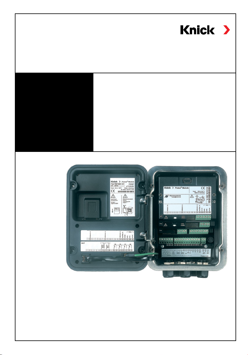
Protos PHU 3400(X)-110 Communication Module
For Actuating Probe Controllers (Unical / Uniclean)
-Automatic pH Measurement-
Latest Product Information: www.knick.de
Page 2

©2017 Subject to change without notice
Return of products under warranty
Please contact our Service Team before returning a defective device. Ship the cleaned device to
the address you have been given. If the device has been in contact with process fluids, it must be
decontaminated/ disinfected before shipment. In that case, please attach a corresponding certificate,
for the health and safety of our service personnel.
Disposal
Please observe the applicable local or national regulations concerning the disposal of
“waste electrical and electronic equipment”.
Trademarks
The following trademarks are used in this manual without further marking:
CalCheck®, Calimatic®, Protos®, Sensocheck®, Sensoface®, Unical®, VariPower®, Ceramat®, SensoGate®
are registered trademarks of Knick Elektronische Messgeräte GmbH & Co. KG, Germany
Memosens®
is a registered trademark of
Endress+Hauser Conducta GmbH & Co. KG, Germany
Knick Elektronische Messgeräte GmbH & Co. KG, Germany
SMARTMEDIA®
is a registered trademark of Toshiba Corp., Japan
Knick
Elektronische Messgeräte GmbH & Co. KG
Beuckestr. 22
14163 Berlin, Germany
Page 3

Table of Contents
Protos PHU 3400(X)-110 Module
Return of products under warranty .................................................................................... 2
Disposal ......................................................................................................................................... 2
Trademarks ................................................................................................................................... 2
Intended Use .................................................................................................... 9
Conformity with FDA 21 CFR Part 11 .................................................................................. 9
Safety Information ........................................................................................ 10
Application in Hazardous Locations: PHU 3400X-110 Module ...............................10
Software Version ......................................................................................................................11
Modular Concept .....................................................................................................................13
Short Description .......................................................................................... 14
Short Description: FRONT Module ....................................................................................14
Short Description: Menu Structure ....................................................................................15
Short Description: BASE Module ........................................................................................ 17
Overview of the System Components .............................................................................18
PHU 3400(X)-110 Module ......................................................................................................20
Terminal Plate PHU 3400(X)-110 Module .................................................... 21
Inserting the Module .................................................................................... 22
Wiring Example VP and SixPlug ..........................................................................................23
Connecting the Probe Controller ................................................................. 25
Menu Selection .............................................................................................. 26
Menu Structure .............................................................................................. 26
Passcode Entry ............................................................................................... 27
Changing a passcode .....................................................................................................27
Configuring the Measurement Display .......................................................28
Start-Up .......................................................................................................... 30
Parameter Setting: Operating Levels .......................................................... 31
Administrator level .........................................................................................................31
Operator level ...................................................................................................................31
Viewing level .....................................................................................................................31
Parameter Setting: Locking a Function ...........................................................................32
3
Page 4

Table of Contents
Protos PHU 3400(X)-110 Module
Parameter Setting for PHU 3400(X)-110 .....................................................33
Activating Parameter Setting ..............................................................................................33
Settings of Sensor Data..........................................................................................................34
Sensoface ....................................................................................................................................36
SW 3400-005: Tolerance Adjustment ................................................................................ 39
Activating the Cal Tolerance Band ............................................................................40
Documenting Parameter Setting .......................................................................................47
ProgaLog 3000 Software (Option) forConfiguration and Documentation .......49
Configuration using "ProgaLog 3000" .....................................................................52
Logbook, Factory Setting ......................................................................................................53
Configuring a Current Output .............................................................................................54
Current Outputs: Characteristics ........................................................................................55
Output Filter ...............................................................................................................................57
NAMUR Signals: Current Outputs ......................................................................................58
NAMUR Signals: Relay Contacts ..........................................................................................59
Relay Contacts: Protective Wiring ......................................................................................60
Relay Contacts, Usage ............................................................................................................61
Relay Contacts: Sensoface Messages ................................................................................62
Rinse Contact .............................................................................................................................63
Limit Value, Hysteresis, Contact Type................................................................................64
Icons in the Measurement Display ....................................................................................64
OK1, OK2 Inputs: Specify Level ...........................................................................................65
Selecting Parameter Set (A, B) via OK2 Input ................................................................66
Signaling Active Parameter Set via Relay Contact .......................................................66
Unical 9000(X) Parameter Setting ............................................................... 67
Cal Preset Values Unical 9000 .....................................................................................68
Time Control ......................................................................................................................68
4
Page 5

Table of Contents
Protos PHU 3400(X)-110 Module
Parameter Setting: Program Flows ....................................................................................70
Cleaning (Continuous), Media Monitoring Off .....................................................70
Cal 2point (Continuous), Media Monitoring Off ..................................................71
Cal 1point (Continuous), Media Monitoring Off ..................................................72
Parking .................................................................................................................................74
Measurement (Short-Time), Media Monitoring Off ............................................75
Cal 2point (Short-Time), Media Monitoring Off ...................................................76
Cal 1point (Short-Time), Media Monitoring Off ...................................................77
Service .................................................................................................................................78
Configuring the Program Flow ...................................................................................79
Entering a Program Name ............................................................................................79
Editing a Program Step .................................................................................................79
Configuring a Function .................................................................................................80
Activating Monitoring ...................................................................................................80
Parameter Setting: Installation ............................................................................................81
Selecting the Measurement Procedure ...................................................................82
External Control via DCS ...............................................................................................82
Control via Process Control Cystem (DCS) ......................................................................83
Control Programs and Meas. Procedures ........................................................................84
Sensor Detection .............................................................................................................85
Probe ....................................................................................................................................85
Configuring Media Monitoring ...........................................................................................86
Media Adapter ..................................................................................................................87
Additional Media (2) .......................................................................................................87
Start-Up ...............................................................................................................................87
System Forecast (Ceramat, SensoGate) ....................................................... 88
Reference / Probe Travel Profiles ...............................................................................89
Creation of a Probe Travel Profile and Presentation in Protos ........................89
Setting the System Forecast Parameters .........................................................................90
System Forecast: Reference Profile ...........................................................................91
System Forecast: Tolerance Specifications ............................................................. 93
System Forecast: Diagnostic Messages ...................................................................95
System Forecast: RecordingonSmartMediaCard ..............................................96
5
Page 6

Table of Contents
Protos PHU 3400(X)-110 Module
Uniclean 900(X) Parameter Setting ............................................................. 98
Measuring Module ..........................................................................................................99
Time Control ......................................................................................................................99
Parameter Setting: Program Flows ................................................................................. 101
Rinsing (Continuous) ...................................................................................................101
Cleaning (Continuous) ................................................................................................102
Parking .............................................................................................................................. 104
Measuring (Short-Time) .............................................................................................105
Service .............................................................................................................................. 106
Editing a Program Step ..............................................................................................107
Configuring a Function .............................................................................................. 107
Parameter Setting: Installation .........................................................................................108
Selecting a Measurement Procedure .................................................................... 109
External Control via DCS ............................................................................................ 109
Control via Process Control System (DCS) ...................................................................110
Control Programs and Meas. Procedures ..................................................................... 111
Sensor Detection .......................................................................................................... 112
Probe ................................................................................................................................. 112
Media Adapter ............................................................................................................... 113
Additional Media (2) .................................................................................................... 113
Start-Up ............................................................................................................................ 113
Calibration / Adjustment ............................................................................114
Calibration Methods ............................................................................................................ 116
One-Point Calibration ................................................................................................. 116
Two-Point Calibration ................................................................................................. 116
Three-Point Calibration .............................................................................................. 116
Sensor Replacement (First Calibration) ................................................................ 116
Temperature Compensation ............................................................................................. 117
Automatic Calibration .........................................................................................................118
Manual Electrode Calibration ........................................................................................... 120
HOLD Function During Calibration ................................................................................ 122
6
Page 7

Table of Contents
Protos PHU 3400(X)-110 Module
Selecting a Calibration Method ....................................................................................... 123
Calimatic Automatic Buffer Recognition .............................................................124
Calibration with Manual Entry of Buffer Values ................................................ 126
Product Calibration .....................................................................................................128
Calibration by Entering Data from Premeasured Electrodes ....................... 130
ORP Calbration/Adjustment .................................................................................... 132
ISFET Zero Adjustment ..............................................................................................134
Maintenance of PHU 3400(X)-110 ..............................................................136
Sensor Monitor ....................................................................................................................... 136
Temp Probe Adjustment.....................................................................................................136
Probe Maintenance via Protos 3400(X) .....................................................137
Diagnostics Functions ................................................................................. 141
Point of Meas Description ......................................................................................... 141
Logbook ........................................................................................................................... 141
Device Description ....................................................................................................... 142
Diagnostics of PHU 3400(X)-110 ..................................................................................... 143
Module Diagnostics.............................................................................................................. 143
Sensor Monitor .............................................................................................................. 143
Calibration Timer .......................................................................................................... 144
Tolerance Adjustment .................................................................................................144
Cal Record ....................................................................................................................... 145
Sensor Network Diagram .......................................................................................... 145
Statistics ........................................................................................................................... 145
Diagnostics of Unical 9000(X) ...........................................................................................146
Unical Status ................................................................................................................... 146
Unical Network Diagram ........................................................................................... 146
Diagnostics of Uniclean 900(X) ........................................................................................ 147
Uniclean Status .............................................................................................................. 147
Diagnostic Messages of System Forecast ..................................................................... 148
Setting Diagnostics Messages as Favorite ................................................149
7
Page 8

Table of Contents
Protos PHU 3400(X)-110 Module
Message List ........................................................................................................................... 151
Messages ...................................................................................................... 152
System Forecast Messages ................................................................................................ 161
Error Messages of Unical 9000(X) .................................................................................... 162
Error Messages of Uniclean 900(X) ................................................................................. 168
Specifications ...............................................................................................172
Appendix: ..................................................................................................... 176
Minimum Spans for Current Outputs ............................................................................ 176
Buffer Table "Mettler-Toledo" ............................................................................................ 177
Buffer Table "Knick CaliMat" .............................................................................................. 178
Buffer Table "DIN 19267" .................................................................................................... 179
Buffer Table "NIST Standard" (DIN 19266: 2000-01).................................................. 180
Buffer Table "Techn. Buffers to NIST" .............................................................................. 181
Buffer Table "Hamilton" ....................................................................................................... 182
Buffer Table "Kraft" ................................................................................................................ 183
Buffer Table "Hamilton A" ................................................................................................... 184
Buffer Table "Hamilton B" ................................................................................................... 185
Buffer Table "HACH" ............................................................................................................. 186
Buffer Table "Ciba"................................................................................................................. 187
Buffer Table "Reagecon"...................................................................................................... 188
SW 3400-002: Specifiable Buffer Sets ............................................................................ 189
Overview of Parameter Setting ..................................................................190
Index ............................................................................................................. 196
Menu Selection ............................................................................................ 210
Quick Access .................................................................................................211
8
Page 9

Intended Use
The module is used for simultaneous pH, ORP, and temperature measurement
with glass electrodes. It allows connection of the Unical 9000(X) probe controller for fully automated pH measurement, cleaning, and calibration or the
Uniclean 900(X) for fully automated pH measurement.
The PHU 3400X-110 module is intended for operation in locations subject to
explosion hazards which require equipment of Group II, device category 2(1),
gas/dust.
Conformity with FDA 21 CFR Part 11
In their directive “Title 21 Code of Federal Regulations, 21 CFR Part 11,
Electronic Records; Electronic Signatures“ the US American health agency FDA
(Food and Drug Administration) regulates the production and processing of
electronic documents for pharmaceutical development and production. This
results in requirements for measuring devices used for corresponding applications. The following features ensure that the Protos 3400(X) modular process
analysis system meets the demands of FDA 21 CFR Part 11:
Electronic Signature
Access to the device functions is regulated and limited by individually adjustable codes – “Passcodes“. This prevents unauthorized modification of device
settings or manipulation of the measurement results. Appropriate use of these
passcodes makes them suitable as electronic signature.
Audit Trail Log
Every change of device settings can be automatically recorded and documented in the Audit Trail Log on the SmartMedia card. The recording can be
encrypted.
9
Page 10

Safety Information
Application in Hazardous Locations
Caution!
Never try to open the module! If a repair should be required, return the module
to our factory.
If the specifications in the instruction manual are not sufficient for assessing
the safety of operation, please contact the manufacturer to make sure that your
intended application is possible and safe.
Be sure to observe during installation:
• Switch off power supply before replacing or inserting a module.
• Protect the signal inputs of the modules against electrostatic discharge.
• Before commissioning it must be proved that the device may be connected
with other equipment.
• Observe correct shielding: To avoid interferences, the cable shielding must
be completely covered by the ESD shielding cap.
Application in Hazardous Locations: PHU 3400X-110 Module
The module is approved for operation in hazardous locations.
Observe all applicable local codes and standards for the installation of electrical
equipment in hazardous locations. For orientation, please refer to
IEC 60079-14, EU directives 2014/34/EU and 1999/92/EC (ATEX), NFPA 70 (NEC),
ANSI/ISA-RP12.06.01.
• When installing the device in a hazardous location, observe the specifications of the EC-Type-Examination Certificate and, if applicable, of the Control
Drawing (download: www.knick.de).
• Before commissioning you must prove that the device may be connected
with other equipment, such as a supply unit including cables and wires.
• In hazardous locations the device shall only be cleaned with a damp cloth to
prevent electrostatic charging.
• Devices and modules which have already been used shall be subjected to
a professional routine test before they may be operated in another zone or
another type of protection.
10
Page 11
Software Version
PHU 3400(X)-110 Module
Device Software Protos 3400(X)
The PHU 3400(X)-110 module is supported by software version 5.0
or higher.
Module Software PHU 3400(X)-110
Software version 3.x
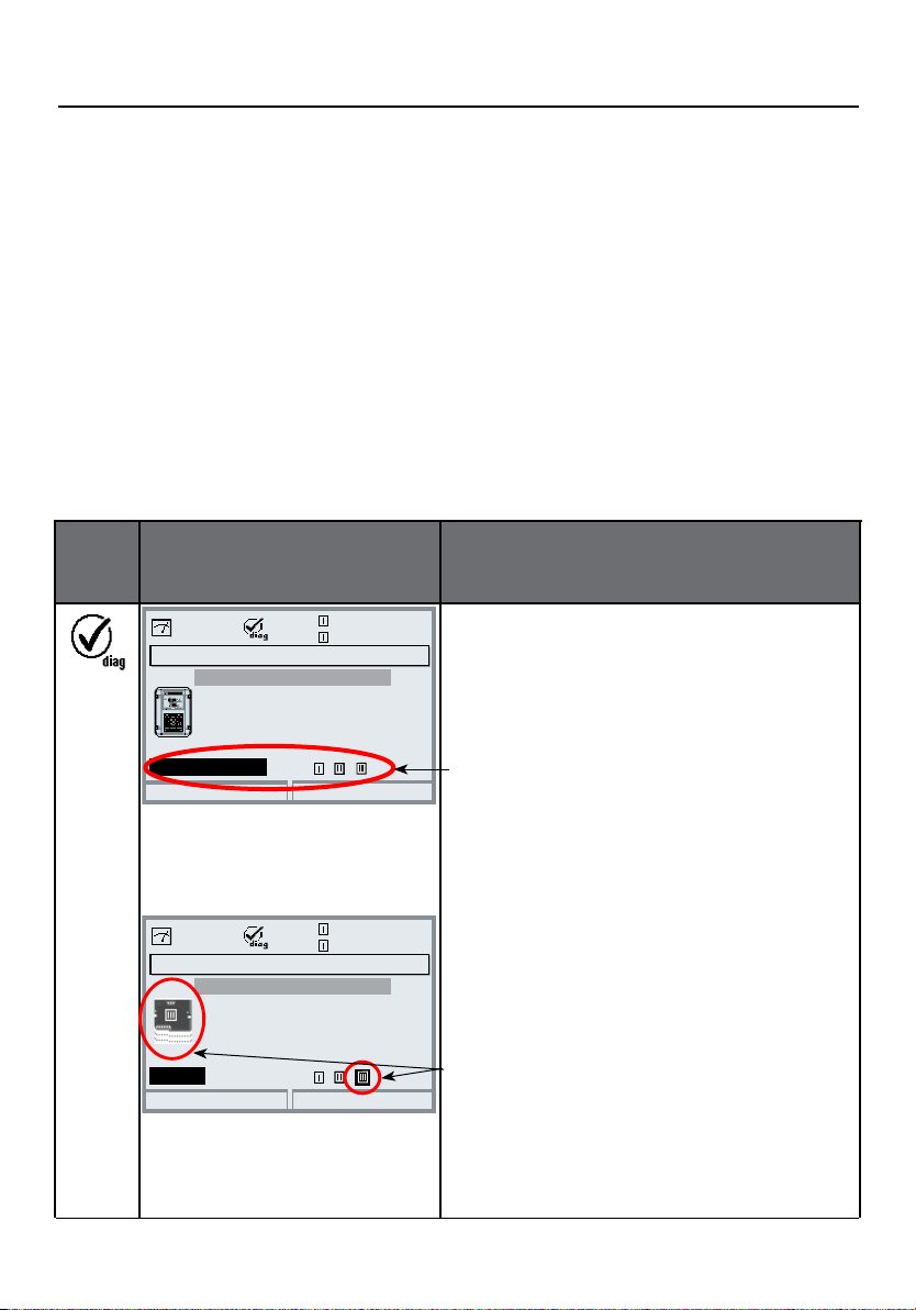
Query actual device/module software
When the analyzer is in measuring mode:
Press menu key, open Diagnostics menu: Device description
Menu Display Device description
Device description
Module FRONT 3400-011
Operating panel Protos
Hardware: 1.1, Software: A.2
Serial number: 08150815
Module
FRONT
Return
Device description
Module PHU 3400-110
Input for pH, ORP and °C
Hardware: 1, Software: 3.0
Serial number: 471101147
Module
FRONT
Return
BASE
BASE
7.00 pH
22.7 °C
Options
7.00 pH
22.7 °C
Options
Device hardware and software
version
Provides information on all modules
installed: Module type and function,
serial number, hardware and software
version and device options.
Select the different modules (FRONT,
BASE, slots 1 - 3) using the arrow keys.
Query module software
Module PHU 3400-110,
hardware and software version,
serial number –
here installed in slot3.
11
Page 12

12
Page 13
Modular Concept
Basic unit, measuring modules, additional functions
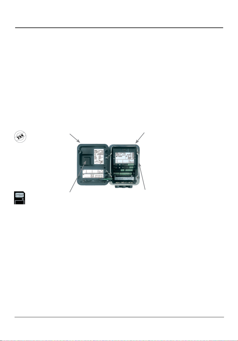
The Protos 3400(X) is an expandable modular process analysis system.
The basic unit (FRONT and BASE modules) provides three slots which can be
equipped by the user with any combination of measuring or communication
modules. The software capabilities can be expanded by additional functions
(options). Additional functions must be ordered separately. They are supplied
with a device-specific TAN for function release.
Protos 3400(X) Modular Process Analysis System
Additional functions
Activation via
device-specific TAN
SmartMedia card
Data recording
ProgaLog 3000
Windows® software for
parameter setting and
data evaluation
3 module slots
for free combination of
measuring and communication
modules
Measuring modules
• pH / ORP / Temp
• O2 / Temp
• Noncontacting conductivity / Temp
• Contacting conductivity / Temp
• Memosens sensors
Communication modules
• OUT (additional switching and current
outputs)
• PID (analog and digital controller)
• Profibus PA
• Foundation Fieldbus
• FIU (radio, Memosens, Unical)
(software occupies 2 slots)
• Unical probe controller
Documentation
The basic unit is accompanied by a CD-ROM containing the complete
documentation.
Latest product information as well as user manuals for earlier software
releases are available at
www.knick.de.
13
Page 14
Short Description
Short Description: FRONT Module
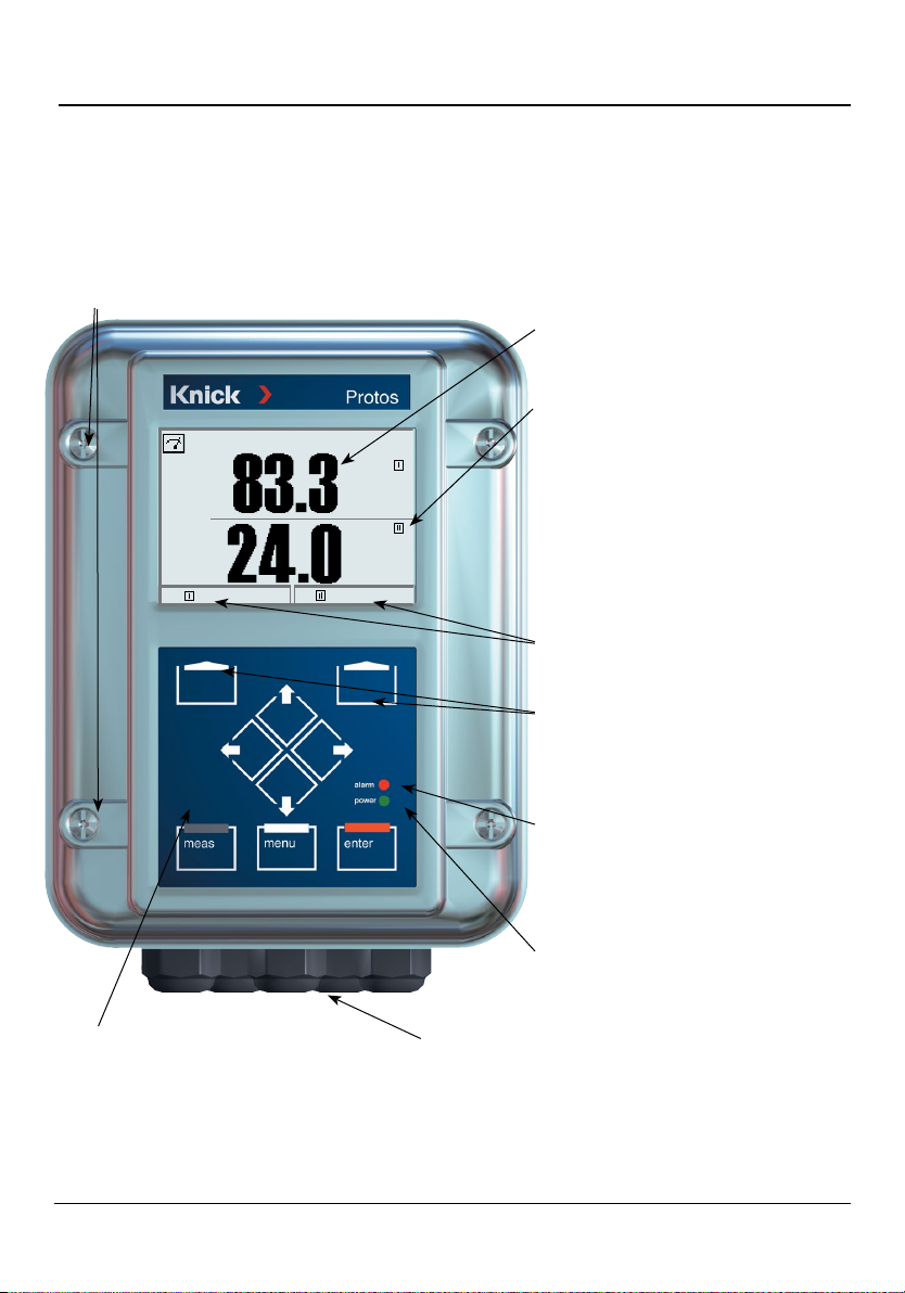
4 captive screws
for opening the analyzer
(Caution! Make sure that the gasket between FRONT and
BASE is properly seated and clean!)
%Air
°C
24.0°C
25.8°C
Transflective LC graphic display
(240 x 160 pixels)
white backlighting, high resolution and
high contrast.
Measurement display
User interface
with plaintext menus as recommended by NAMUR.
Menu texts can be switched to:
German, English, French, Italian,
Swedish/Portuguese or Spanish.
Intuitively acquirable menu logic,
based on Windows standards.
Secondary displays
2 softkeys
with context-sensitive functions.
Red LED
signals failure (On) or
maintenance request/function check
(flashing) according to NE 44.
Control panel
3 function keys
(menu, meas, enter)
and 4 arrow keys for menu selection
and data entry
14
Green LED
Voltage supply okay
5 self-sealing cable glands
M20 x 1.5
for entry of voltage supply and signal lines
Page 15
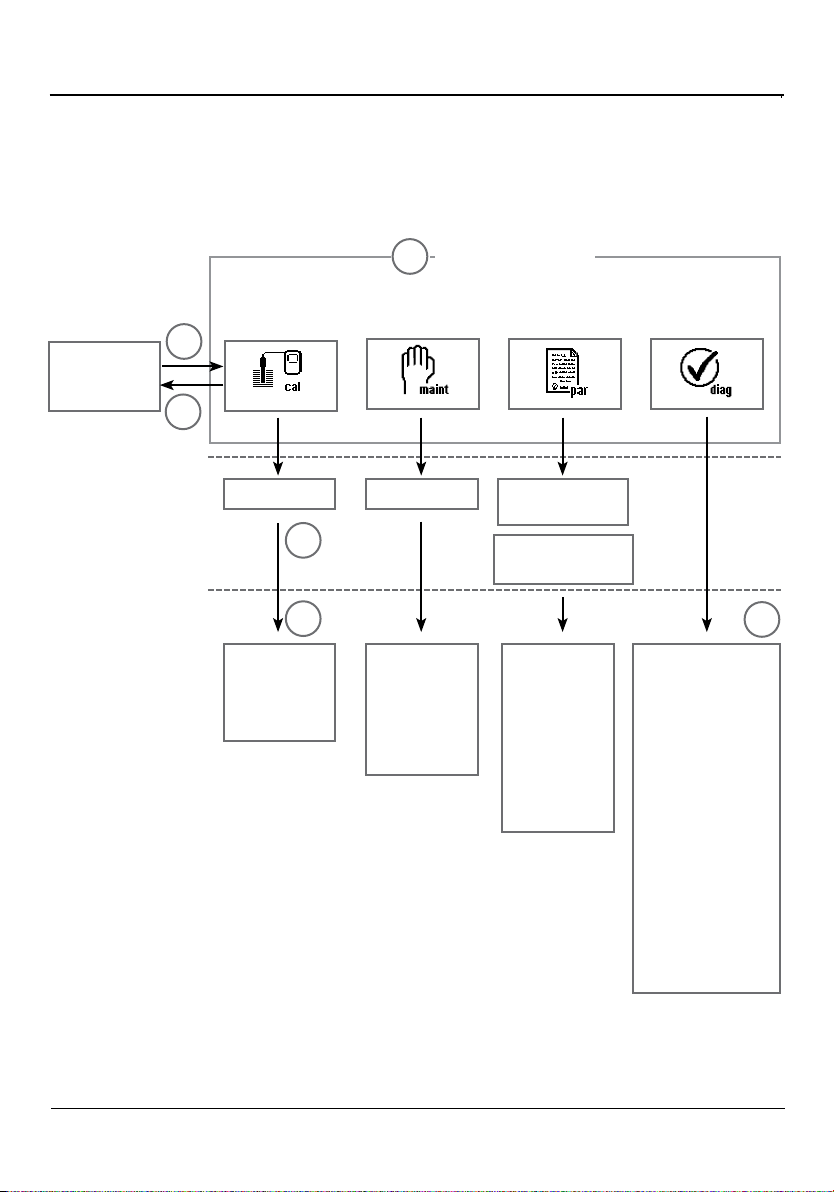
Short Description: Menu Structure
Basic functions: Calibration, Maintenance, Parameter setting, Diagnostics
3
Menu groups
Parameter setting
1
Calibration
Maintenance
Measure
2
Passcode:
Selection of
further
menu items:
1147
4
5
Module 1
Module 2
Module 3
2958
BASE
Module 1
Module 2
Module 3
1246
Operator level
1989
Administrator level
SYSTEM
FRONT
BASE
Module 1
Module 2
Module 3
Legend:
1) Pressing the menu key accesses menu selection.
2) Pressing the meas key returns to measurement.
3) Menu groups are selected using the arrow keys
4) Press enter to confirm, enter passcode
5) Further menu items are displayed
6) Selected functions of the Diagnostics menu can be recalled
via softkey even when in measuring mode
Diagnostics
6
Message list
Point of meas
description
Logbook
Device description
FRONT
BASE
Module 1
Module 2
Module 3
15
Page 16
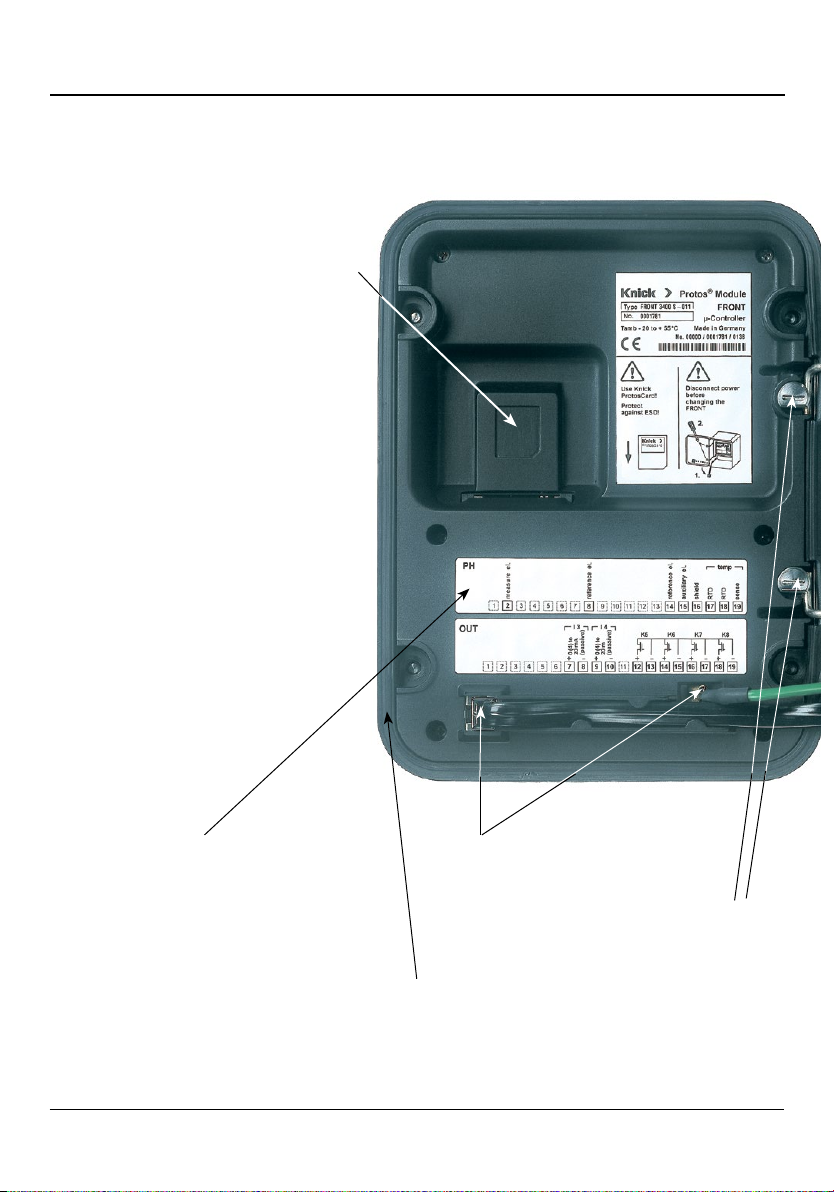
Short Description: FRONT Module
View into the open device (FRONT module)
Slot for SmartMedia card
• Data recording
The SmartMedia card expands the
measurement recorder capacity to
> 50000 records.
• Exchange of parameter sets
5 parameter sets can be stored on the
SmartMedia card, 2 of them can be
loaded simultaneously to the analyzer
and be switched by remote control.
Parameter sets can be transmitted
from one analyzer to the other.
• Function expansions
are possible with additional software
modules, which are released using
transaction numbers (TAN).
• Software updates
Terminal plates
of “hidden” modules
Each module comes with an adhesive label
containing the contact assignments. This
label should be sticked to the inner side
of the front (as shown). Then, the terminal
assignments remain visible even if further
modules are inserted.
16
Replacing the front module
Pull off power cord and ground wire.
To separate the FRONT module from
the BASE module, turn the retaining screws
of the pivot hinge by 90°.
The circumferential sealing
guarantees IP 65 protection and allows spray
cleaning / disinfection.
NOTICE! Keep clean!
Page 17
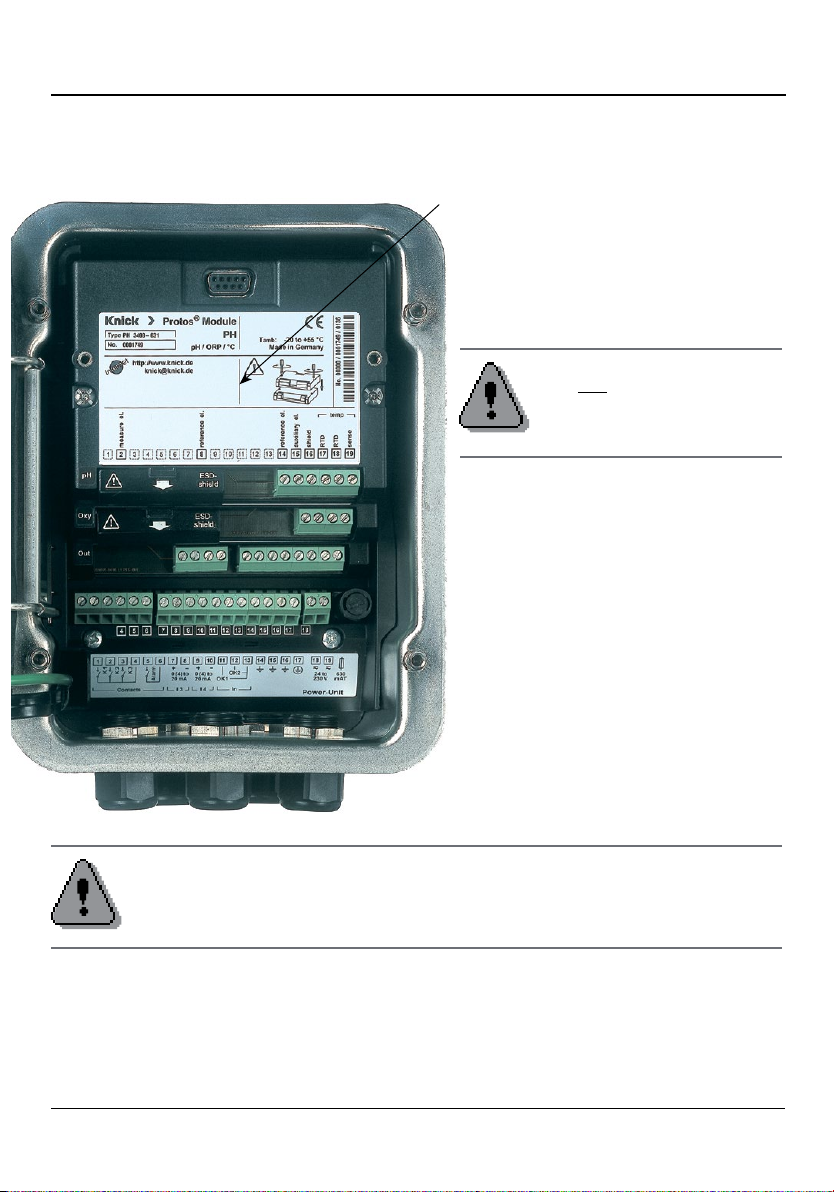
Short Description: BASE Module
View into the open device (BASE module, 3 function modules installed)
Module equipment
Module identification: Plug & Play.
Up to 3 modules can be combined as
desired. Several input and communication
modules are available.
Note
Only one module can be
connected in addition to a
FIU 3400(X)-140/141 module.
BASE module
2 current outputs (free assignment of process variable) and 4 relay contacts,
2 digital inputs.
VariPower broad-range power supply unit,
20 ... 265 V AC/DC, suitable for all public
mains supplies in the world.
Power supply units, Ex version:
100 ... 230 V AC or
24 V AC/DC
WARNING!
Do not touch the terminal compartment,
there may be dangerous contact voltages!
Important notice concerning SmartMedia Card
The SmartMedia card may be inserted or replaced with the power supply
switched on. Before a memory card is removed, it must be “closed” in the maintenance menu. When closing the device, make sure that the sealing is properly
seated and clean.
17
Page 18
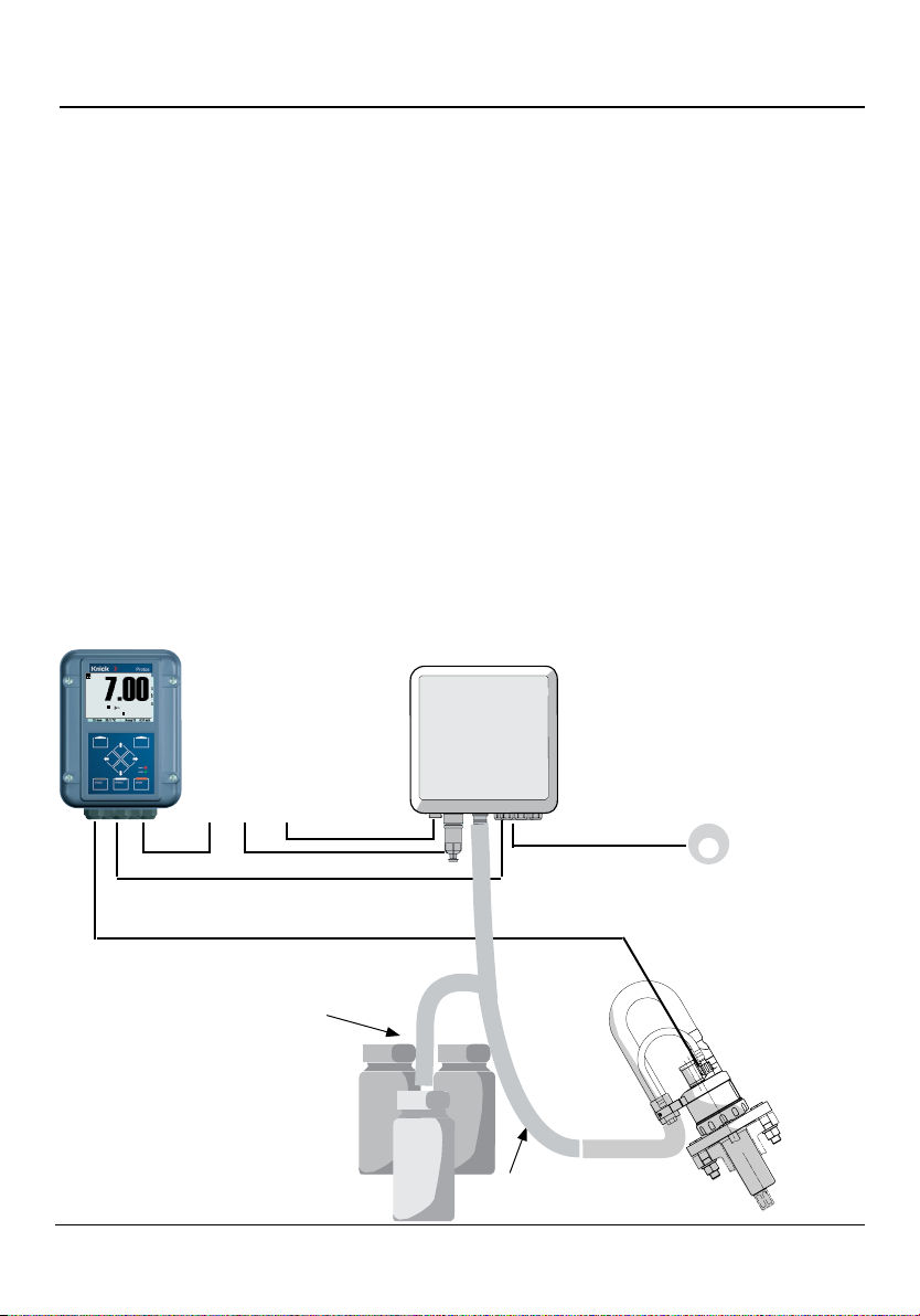
Overview of the System Components
Fully Automated Process Analysis System
The fully automated process analysis system consists of the following
components
• Protos 3400(X) (modular process analysis system)
• Unical 9000(X) / Uniclean 900(X) (automatic control of retractable fittings)
• Ceramat WA 150(X) (retractable fitting with ceramic sealing to the process)
The system is operated from the Protos 3400(X). Four operating modes are
provided: calibration, parameter setting, maintenance, diagnostics.
The PHU 3400(X)-110 module consists of 2 functional groups:
• PHU 3400(X)-110 (measuring circuit)
• Unical 9000(X) / Uniclean 900(X) (probe control)
Protos 3400(X)
pH
25.6 °C09.03.07
Max. 10 m
To probe (pH/temp) max. 20 m
Media adapter
with metering
pumps
(calibration buffers,
cleaning agent
Compressed air
Power supply
e.g. Unical 9000(X)
Service
Rinse water
Media connection
Max. 10 m
Max. 10 m
switch
Ceramat WA 150(X)
with pH sensor
18
Page 19
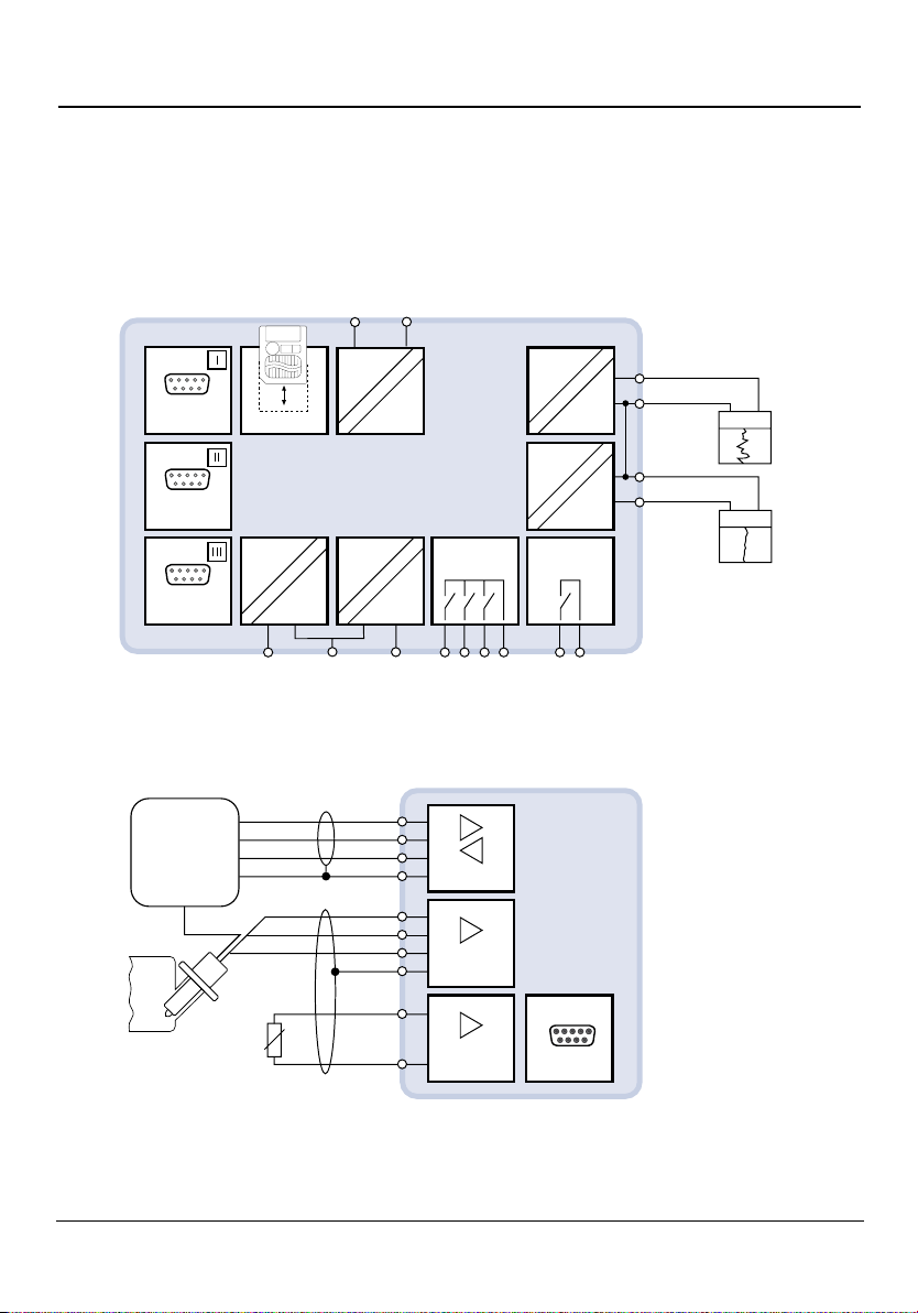
Overview of the System Components
Protos 3400(X) Basic Unit and Controller Module for Retractable Fittings
PHU 3400(X)-110 and Unical 9000(X) / Uniclean 900(X) Probe Controller
Protos 3400(X) basic unit.
The PHU 3400(X)-110 module is located in one of the 3 module slots available.
Module
slot
Module
slot
Module
slot
SMARTMEDIA
OK 1
VariPower
Protos 3400(X)
OK 2
Contacts
K1, K2, K3
I 1
I 2
Alarm
K4
mA
mA
PHU 3400(X)-110 controller module for retractable fittings
and Unical 9000(X) / Uniclean 900(X) probe controller:
Unical 9000 (X)
or
Uniclean 900(X)
Unical
pH, ORP
MΩ, kΩ
PHU 3400(X)-110
module
0(4) ... 20 mA
pH
0(4) ... 20 mA
Temp
Probe
RTD
Temp
Interface
19
Page 20

PHU 3400(X)-110 Module
Measuring Circuit and Probe Control Function Blocks
For a direct access to the function descriptions related to the Unical 9000(X)/
Uniclean 900(X) probe controller, please refer to the overview on the back page
of this manual.
You can document your specific settings for the Unical 9000(X) / Uniclean
900(X) probe controller in the Excel spreadsheet from the CD-ROM
(supplied with Protos 3400(X) or as download at www.knick.de)
Measuring Circuit and Probe Control Function Blocks
Probe Controller
The PHU 3400(X)-110 module allows connection of the Unical 9000(X) probe
controller for fully automated pH measurement, cleaning, and calibration or
the Uniclean 900(X) probe controller for fully automated pH measurement.
Measuring Circuit
Even without the Unical 9000(X) / Uniclean 900(X), the PHU 3400(X)-110
module is a fully fledged pH measuring module for simultaneous pH, ORP and
temperature measurement with glass electrodes.
This instruction manual describes the whole functionality of the
PHU 3400(X)-110 module corresponding to the following menu groups:
• Calibration
• Maintenance
• Parameter setting
• Diagnostics
The Protos 3400(X) is an expandable modular process analysis system.
For latest product information, please refer to:
www.knick.de
20
Page 21
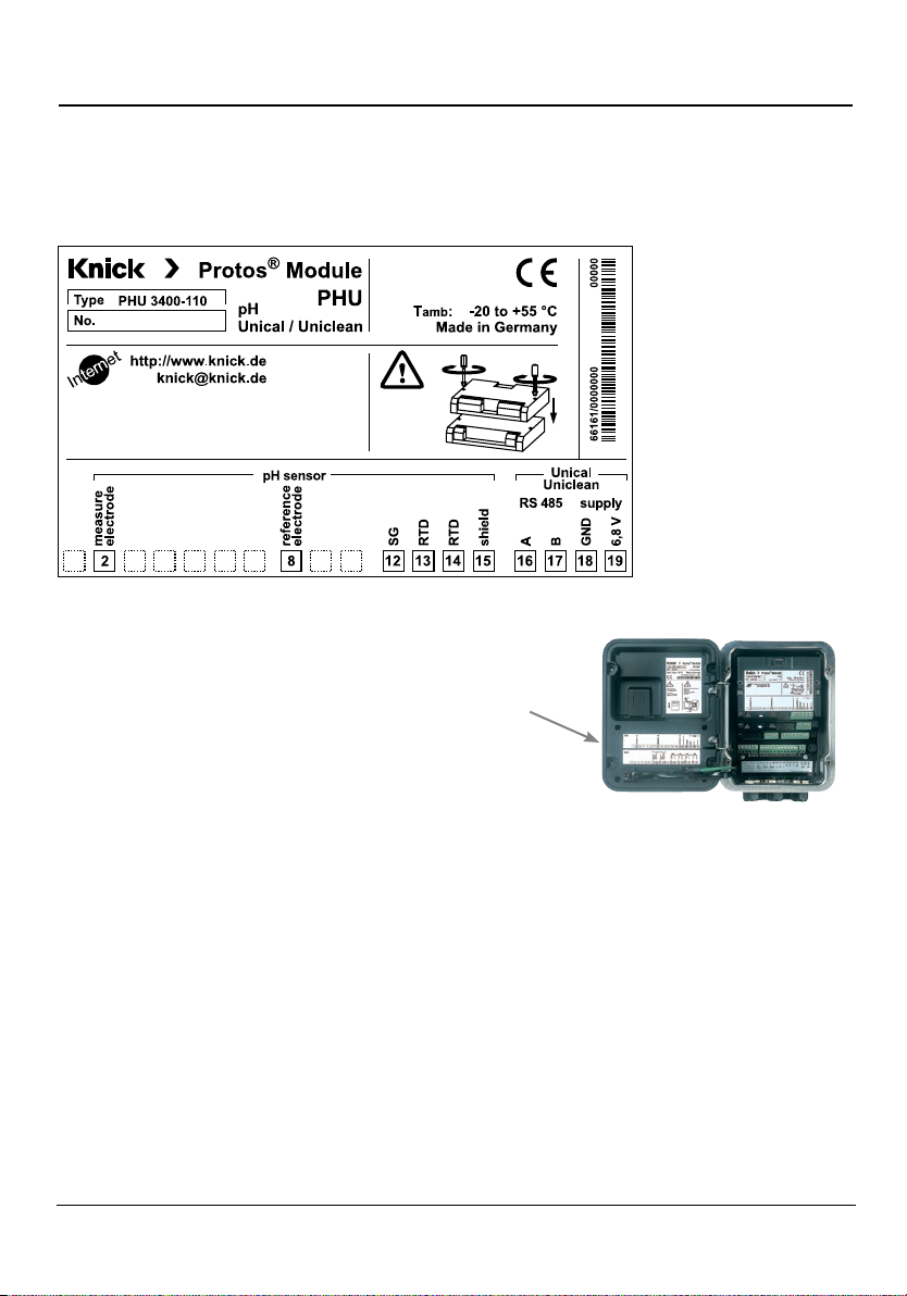
Terminal Plate PHU 3400(X)-110 Module
Terminal Plate PHU 3400-110 Module:
Attaching the Terminal Plates
The terminal plates of the lower modules can
be sticked to the inner side of the door.
This facilitates maintenance and service.
21
Page 22
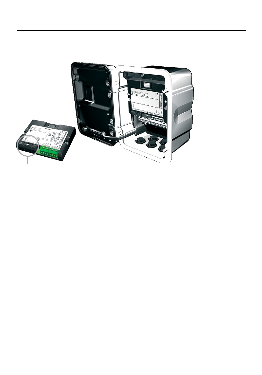
Inserting the Module
Note: Be sure to connect the shielding properly!
The terminals 2 and 8 are
covered by an ESD shield.
To connect the sensor cable,
just pull it back.
Switch off power supply
1.
Open the device (loosen the 4 screws at the front)
2.
Place module in slot (D-SUB connector)
3.
Tighten fastening screws of the module
4.
Open ESD shielding cap (covering terminals 2 and 8)
5.
Connect sensor cable.
6.
To avoid interferences, the cable shielding must be completely
covered by the ESD shielding cap.
Close ESD shielding cap (covering terminals 2 and 8)
7.
Connect RS 485 interface to probe controller
8.
(terminals 16 ... 19)
Close device, tighten screws at the front
9.
Switch on power supply
10.
Set parameters
11.
Make sure that the cable
glands are tightly closed to
protect against humidity.
22
Page 23
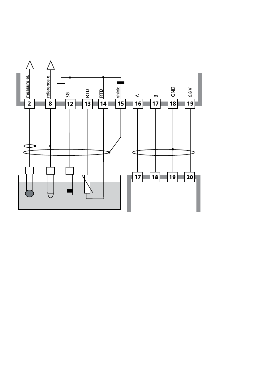
Wiring Example 1
Wiring Example VP and SixPlug
Multisense electrode (pH/ORP/temp) with solution ground (SG)
PHU 3400-110
Green
Core
Shield
Blue
Green
White
GN/YE
Yellow
Brown
White
UNICAL 9000(X)
23
Page 24
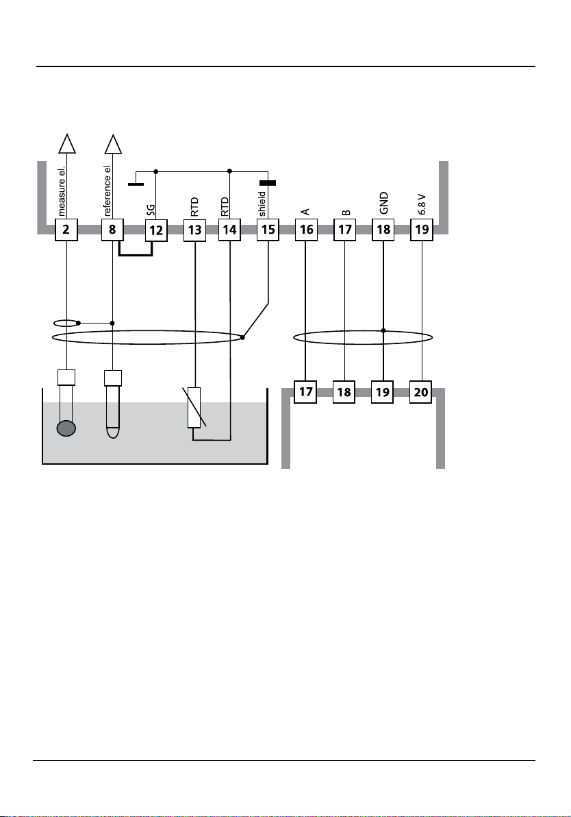
Wiring Example 2
Wiring Example VP and SixPlug
Electrode (pH/temp) without solution ground (SG)
PHU 3400-110
Jumper
GN/YE
Green
Core
Shield
White
Green
Yellow
Brown
White
24
UNICAL 9000(X)
Page 25
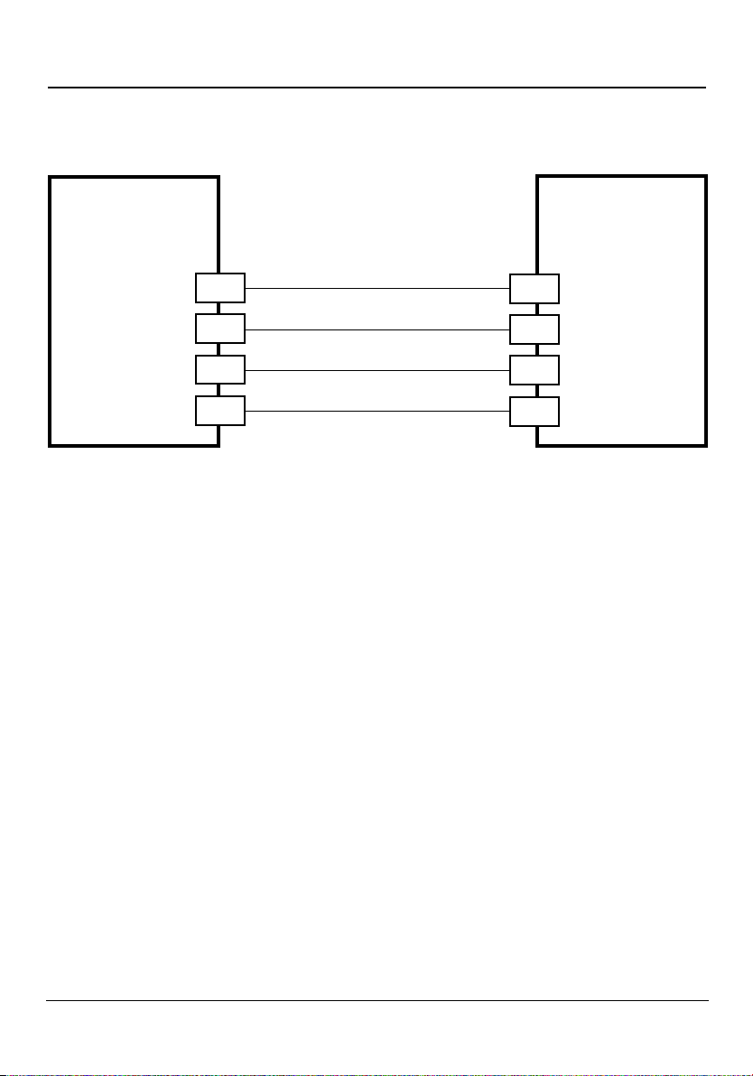
Connecting the Probe Controller
Probe Controller for Fully Automated Measurement, Cleaning and Calibration
Unical 9000X
Uniclean 900(X)
RS 485 A
RS 485 B
GND
Power
Unical 9000(X) / Uniclean 900(X) Controller
The Unical 9000(X) / Uniclean 900(X) probe controllers come with
installation manuals, free download at www.knick.de.
17
18
19
20
Green
Yellow
Brown
White
Protos module
PHU 3400(X)-110
16
RS 485 A
17
RS 485 B
GND
18
6.8 V (supply)
19
25
Page 26
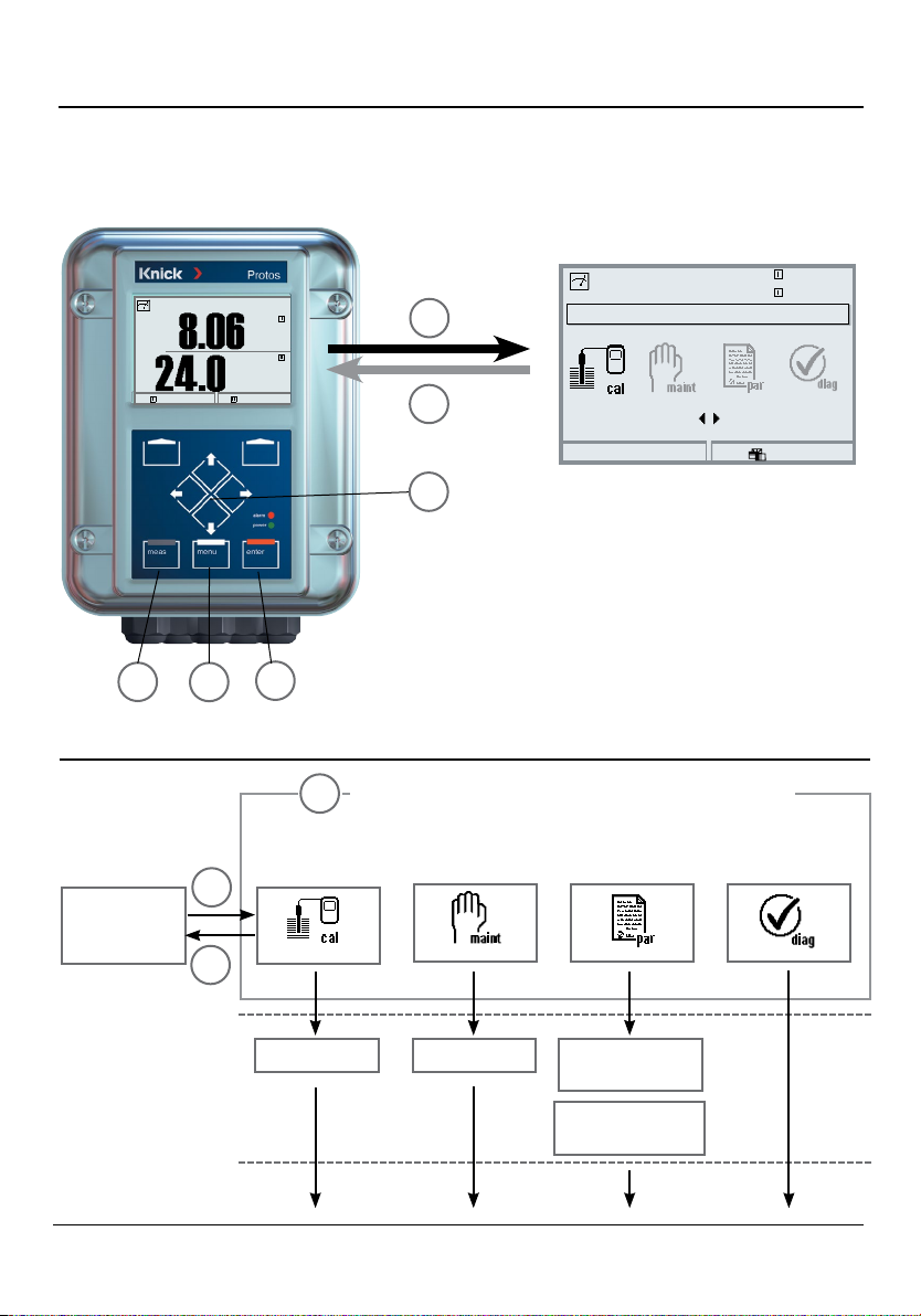
Menu Selection
After switching on, the analyzer performs an internal test routine and
automatically detects the number and type of modules installed.
Then, the analyzer goes to measuring mode.
Menu selection
Select:
Return to meas
[enter]
24.0°C
pH
°C
25.8°C
1
2
3
1 Pressing menu accesses menu selection.
2 Pressing meas returns to measurement.
3 Arrow keys for selecting a menu group
4 enter key for confirming a selection
8.06 pH
25.1 °C
Lingua
2
4
1
Menu Structure
Calibration Maintenance Parameter setting Diagnostics
1
Measuring
2
Passcode
1147
(as delivered)
Selection of further
menu items:
26
3
Menu groups (Select using arrow keys)
2958
1246
Operator level
1989
Administrator level
Page 27
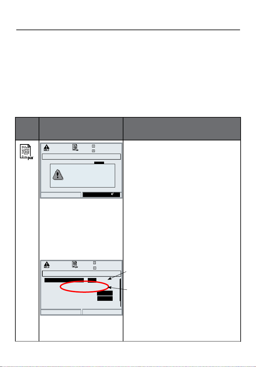
Passcode Entry
To enter a passcode
Select the position using the left/right keys,
then edit the number using the up/down keys.
When all numbers have been entered, press enter to confirm.
To change a passcode
• Open the menu selection (menu)
• Select parameter setting
• Administrator level, enter passcode
• Select System control: Passcode entry
Menu
Display
Passcode entry (Administrator)
cal
Calibration
maint
opl
Passcode entry (Administrator)
cal
maint
opl
If you lose the
adm passcode, system
access will be locked!
Calibration
Change passcode
Maintenance
Operator level
Return Info
On
Close
7.00 pH
25.6 °C
Off
OK
7.00 pH
25.6 °C
On Off
1147
On
Off
On
Off
System control:
Passcode entry
Changing a passcode
“Passcode entry” menu
When this menu is opened, the
analyzer displays a warning (Fig.).
Passcodes (factory settings):
Calibration 1147
Maintenance 2958
Operator level 1246
Administrator level 1989
If you lose the passcode
for the Administrator level, system
access will be locked! Please consult
our technical support!
To change a passcode
Select “On” using arrow keys,
confirm with enter.
Select the position using the left/right
keys, then edit the number using the
up/down keys.
When all numbers have been entered,
confirm with enter.
27
Page 28
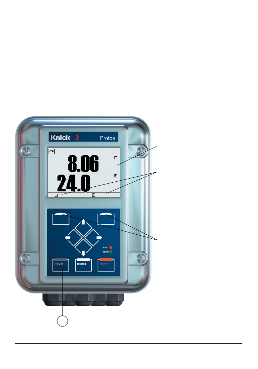
Configuring the Measurement Display
Select menu: Parameter setting/Module FRONT/Measurement display
Pressing meas (1) returns the analyzer to the measuring mode from any
function.
All process variables coming from the modules can be displayed.
The table on the next page describes how to configure the measurement
display.
Measurement display
Typical measurement display
24.0°C
1
pH
°C
25.8°C
Secondary displays
Additional values, also date and
time, can be displayed depending
on the modules installed.
Softkeys
In measuring mode, the softkeys
allow selection of values for the
secondary displays or control of
functions (user defined).
28
Page 29
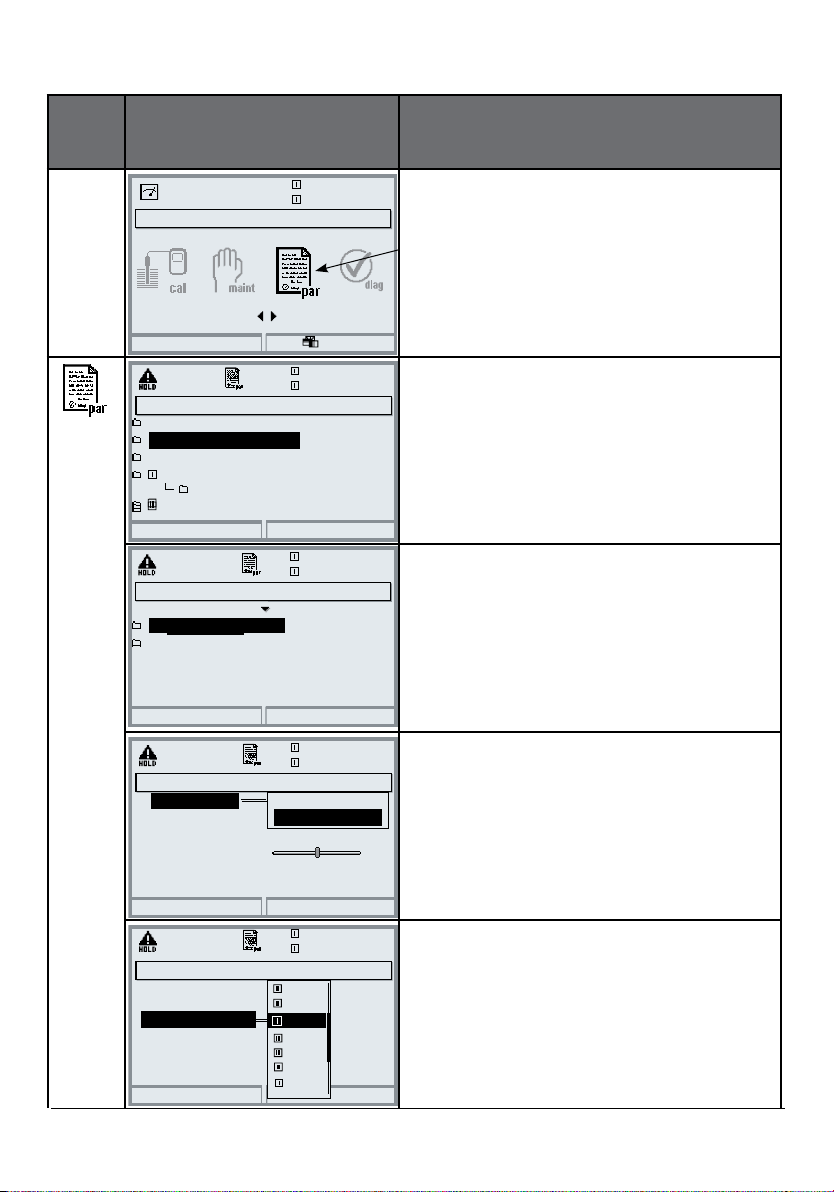
Menu Display Configure measurement display
7.00 pH
Menu selection
Select:
Return to meas
Parameter setting (Administrator)
System control
Module FRONT 3400-011
Module BASE 3400-021
Module PHU 3400-110
Probe control
Module PH 3400-035
Return
Module FRONT 3400-011 (Administrator)
Languages
Measurement display
Measurement recorder
Return
Measurement display (Administrator)
Main display
1st primary value
2nd primary value
Viewing angle
25.6 °C
[enter]
Lingua
7.00 pH
25.6 °C
7.00 pH
25.6 °C
English
7.00 pH
+65° C
1 primary value
2 primary values
Configure measurement display
Press menu key to select menu.
Select parameter setting using arrow
keys, confirm with enter. Select:
“Administrator level”: Passcode 1989
(default setting).
Parameter setting:
Select “Module FRONT”
Front module:
Select “Measurement display”
Measurement display:
Set the number of primary values
(large display) to be displayed
%Air
%O
°C
mg/l
mg/l
ppm
mbar
pH
OK
7.00 pH
25.6 °C
2
K
values
Abort
Measurement display (Administrator)
Main display
1st primary value
2nd primary value
Viewing angle
Abort
Select process variable(s) to be displayed and confirm by pressing enter.
To return to measurement:
press meas
29
Page 30
Start-Up
Prerequisite
Mechanical and electrical installation of the components has been performed
according to the separately enclosed operating and installation instructions
(free download at www.knick.de):
• Protos 3400(X)
• Unical 9000(X) or Uniclean 900(X)
• Ceramat WA 150(X) (or other retractable fittings)
Warning!
Before working on the retractable fitting, it must be moved into
SERVICE position. Be sure to read and observe the user manual of
the retractable fitting!
Caution!
Be sure to execute the following steps in the specified order!
1) Insert the PHU 3400(X)-110 module (see Page 22)
2) Connect sensor cable and probe controller (see Pages 23...25)
3) Configure the PHU 3400(X)-110 module (Page 34)
30
Page 31
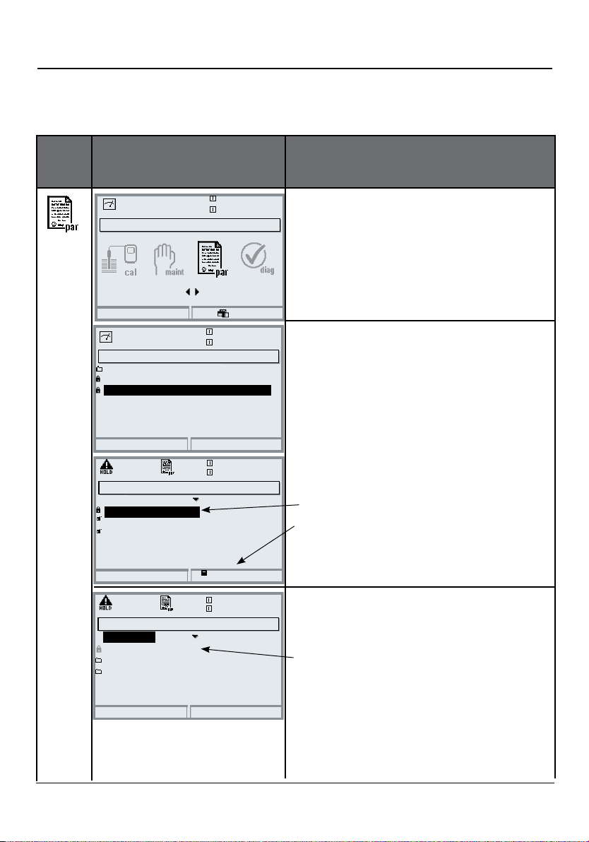
Parameter setting
Parameter Setting: Operating Levels
Viewing level, Operator level, Administrator level
Note: HOLD mode (Setting: BASE module)
Menu
Display
Menu selection
Select:
Return to meas
Parameter setting
Viewing level
Operator level
Administrator level
Return
Module FRONT (Administrator)
Languages
Measurement display
Measurement recorder
KI recorder
[enter]
(All Data) view
(Operation Data) opl
(All Data) adm
English
11.03 pH
25.6 °C
Lingua
11.03 pH
25.6 °C
11.03 pH
25.6 °C
Viewing level, Operator level,
Administrator level
Open parameter setting
From the measuring mode:
Press menu key to select menu.
Select parameter setting using arrow
keys, press enter to confirm.
Administrator level
Access to all functions, also passcode
setting.
Releasing or blocking a function for
access from the Operator level.
Functions which can be blocked for
the Operator level are marked with
the "lock" symbol.
The functions are released or blocked
using the softkey.
Return
Module FRONT
Languages
Measurement display
Measurement recorder
KI recorder
Return
Release
English
11.03 pH
25.6 °C
Operator level
Access to all functions which have
been released at the Administrator
level. Blocked functions are displayed
in gray and cannot be edited (Fig.).
Viewing level
Display of all settings.
No editing possible!
31
Page 32
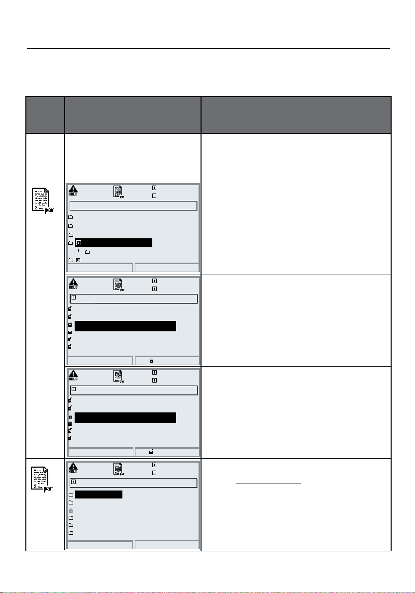
Parameter Setting: Locking a Function
Administrator level: Enabling/locking functions for Operator level
Note: HOLD mode (Setting: BASE module)
Menu Display
Parameter setting (Administrator)
System control
Module FRONT 3400-011
Module BASE 3400-021
Module PHU 3400-110
Probe control
Module PH 3400-035
Return
Module PHU 3400-110 (Administrator)
Input filter
Sensor data
Cal preset values
TC process medium
ORP/rH value
Delta function
Return
Module PHU 3400-110 (Administrator)
Input filter
Sensor data
Cal preset values
TC process medium
ORP/rH value
Delta function
Return
Module PHU 3400-110 (Administrator)
Input filter
Sensor data
Cal preset values
TC process medium
ORP/rH value
Delta function
Return
11.03 pH
25.0°C
11.03 pH
25.0°C
Block
11.03 pH
25.0°C
Release
11.03 pH
25.0°C
Administrator level:
Enabling / locking a function
Example: Blocking access to the
calibration adjustments from the
Operator level
Open parameter setting
Select Administrator level.
Enter passcode (1989).
Select “Module PHU” (for example)
using arrow keys,
press enter to confirm.
Select “Cal preset values”
using arrow keys,
“Block” with softkey.
Now, the “Cal preset values” line is
marked with the “lock” icon.
This function cannot be accessed from
the Operator level any more.
The softkey function changes to
“Release”.
Open parameter setting
Select Operator level,
passcode (1246).
Select “Module PHU” (for example).
Now, the locked function is displayed
in gray and marked with the “lock” icon.
32
Page 33
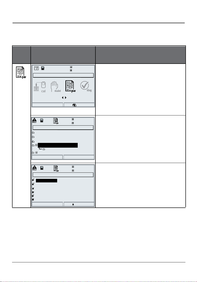
Parameter Setting for PHU 3400(X)-110
Activating parameter setting
Menu Display Parameter setting
11.03 pH
[enter]
25.0°C
Lingua
11.03 pH
25.0°C
11.03 pH
25.0°C
Block
Menu selection
Select:
Return to meas
Parameter setting (Administrator)
System control
Module FRONT 3400-011
Module BASE 3400-021
Module PHU 3400-110
Probe control
Module PH 3400-035
Return
Module PHU 3400-110 (Administrator)
Input filter
Sensor data
Cal preset values
TC process medium
ORP/rH value
Delta function
Return
Activating Parameter Setting
From the measuring mode:
Press menu key to select menu.
Select parameter setting using arrow
keys, press enter to confirm.
Passcode as delivered: 1989
Select "Module PHU 3400-110", press
enter to confirm.
Select parameter using arrow keys,
press enter to confirm.
During parameter setting the analyzer is in HOLD mode:
Current outputs and relay contacts behave as configured (BASE module).
33
Page 34
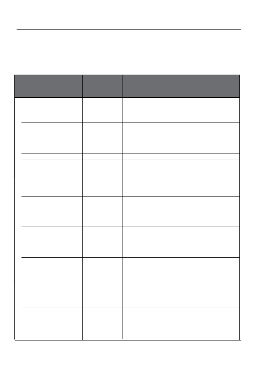
Settings of Sensor Data
With “Auto“, the tolerance limits for the monitoring criteria are determined by
the analyzer. They are displayed in gray. These values cannot be edited.
With ”Individual”, the tolerances can be adjusted.
Note: HOLD mode active.
Parameter Default Selection / Range / Notes
Input filter
• Pulse suppression
Sensor data
• Sensor type
• Temperature detection
- Temperature probe
- Measuring temp
- Cal temp
• Sensoface
• Sensor monitoring details
- Slope
Nominal
Min
Max
Message
- Zero point
Nominal
Min
Max
Message
- Sensocheck Ref el
Nominal
Min
Max
Message
- Sensocheck Glass el
Nominal
Min
Max
Message
- Response time
Response time Max
Message
- Calcheck
Meas distance Max
Message
Off
Standard
Pt 1000
Manual
Manual
Default
Auto
59.2 mV/pH
53.3 mV/pH
61.0 mV/pH
Maint. request
Auto
07.00 pH
06.00 pH
08.00 pH
Maint. request
Auto
5.0 kΩ
3.1 kΩ
100.0 kΩ
Off
Auto
120.0 MΩ
28.6 MΩ
350.0 MΩ
Off
Auto
0000 sec
Off
Auto
3.20 pH
Off
Off, On (suppression of fast transients at the input)
Standard, ISFET (ISFET: Insert PH 3400-032 module)
Pt100, Pt1000, NTC 8.55 kΩ, NTC30kΩ (sensor)
Auto, manual: Default +25.0 °C (entry)
Auto, manual: Default +25.0 °C (entry)
Default, Individual
Auto, Individual
Can only be set with “Individual” selected
Off, failure, maintenance request
Auto, Individual
Can only be set with “Individual” selected
Off, failure, maintenance request
Auto, Individual
Can only be set with “Individual” selected
Off, failure, maintenance request
Auto, Individual (not for sensor type ISFET)
Can only be set with “Individual” selected
Off, failure, maintenance request
Auto, Individual
Off, failure, maintenance request
Calcheck: checks the difference between calibration
buffers and measured values
Auto, Individual
Off, failure, maintenance request
34
Page 35
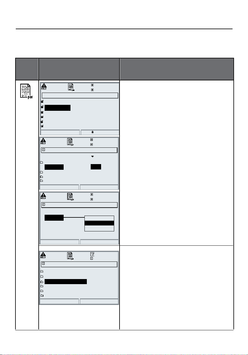
Parameter Setting of PHU 3400(X)-110
Note: HOLD mode active
Menu
Display Display Parameter selection
7.00 pH
Module PHU 3400-110 (Administrator)
Input filter
Sensor data
Cal preset values
TC process medium
ORP/rH value
Delta function
Return
Sensor data (Administrator)
Sensor type
Temperature detection
Sensoface
Slope
Zero
Sensocheck Ref el
Abort
Calcheck (Administrator)
Meas distance max +02.00 pH
Message
Abort
20.1 °C
BlockBlock
7.00 pH
20.1 °C
StandardStandard
(Pt100)
Off
On
OK
7.00 pH
20.1 °C
Off
Failure
Maint. request
OK
Sensor data
Sensor data are preset depending on
the sensor type.
Gray display lines cannot be edited.
Sensoface provides information on
the sensor condition (evaluating the
sensor data).
Great deviations are signaled.
Sensocheck can be switched off.
The following parameters are
monitored: Slope, zero, reference
impedance (for ISFET sensors),
glass impedance (pH electrodes),
response time, CalCheck.
The tolerance limits are displayed in
gray.
Limit violations can be signaled by a
message (either "failure" or
"maintenance request").
Sensor monitoring details
Slope
Zero
Sensocheck Ref el
Sensocheck Glass el
Response time
Calcheck
Abort
(Auto)
(Auto)
(Auto)
(Auto)
(Auto)
(Auto)
7.00 pH
20.1 °C
OK
Sensor monitoring details
With “Auto” selected, the limits
calculated by the analyzer are used
(displayed in gray).
With “Sensor monitoring Individual”,
the tolerance limits for the parameters
are displayed in black and can be set.
35
Page 36
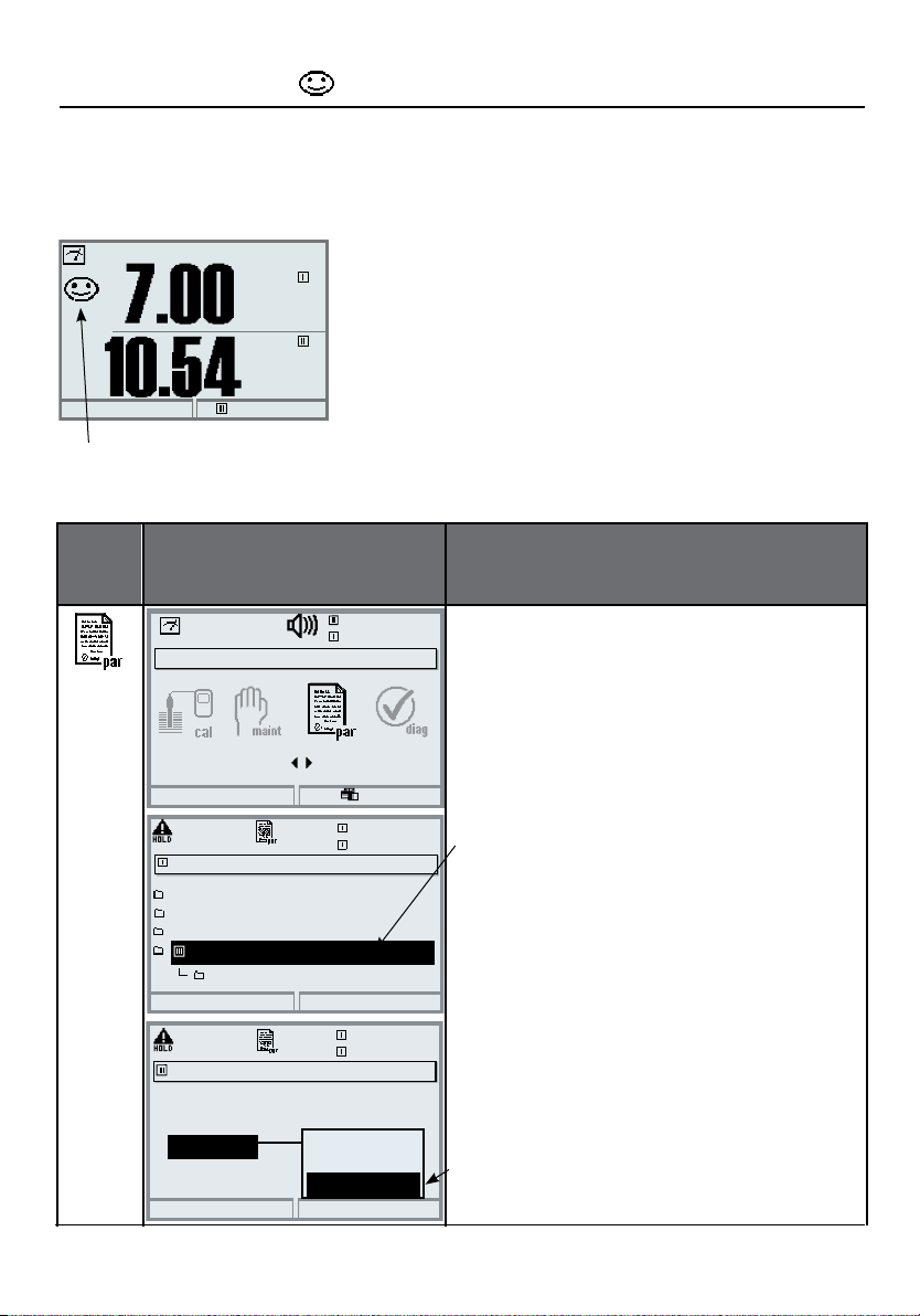
Sensoface
Sensoface is a graphical indication of the sensor condition –
Sensocheck must have been activated during parameter setting.
Sensocheck:
Automatic monitoring of glass and
pH
pH
24.3°C
The “smileys” provide information on wear and required maintenance of the
sensor (“friendly” - “neutral” - “sad”).
Menu Display Activate Sensocheck
reference electrode
Menu selection
Select:
Return to meas
Parameter setting (Administrator)
System control
Module FRONT 3400-011
Module BASE 3400-021
Module PHU 3400-110
Probe control
Return
Sensocheck Ref el (Administrator)
Nominal
Min
Max
Message
Abort
[enter]
005.0 kOhm
003.1 kOhm
100.0 kOhm
Off
Failure
Maint. request
7.00 pH
25.6°C
Lingua
7.00 pH
25.6°C
7.00 pH
25.6°C
OK
Open menu selection
Select parameter setting
Enter passcode (Administrator)
Select (“PHU”) module.
Confirm with enter
Select “Sensor data”.
Confirm with enter.
Then select “Sensocheck Ref el”.
(Fig.)
Assign function and
confirm with enter.
36
Page 37
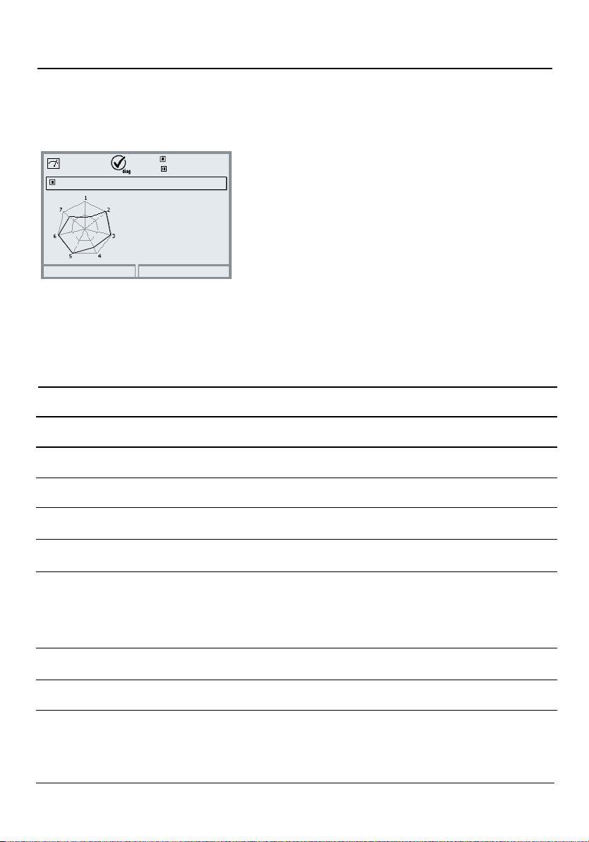
Sensoface is “sad” ...
The “Diagnostics / Module PHU / Sensor network diagram”
shows all current sensor parameters in a graphic diagram.
Sensor network diagram
1 - Slope
2 - Zero point
3 - Ref impedance
4 - Glass impedance
5 - Response time
6 - Cal timer
7 - Calcheck
Return
Sensoface Criteria
Parameter
Slope
Zero
Reference impedance
Glass impedance
7.00 pH
24.1°C
Info
Standard*
59.2
7.00
Rcal **
Rcal **
Sensor Network Diagram
“Diagnostics / Module PHU / Sensor network
diagram”.
Tolerance limit violations can be seen at a
glance. Critical parameters (inner circle) are
flashing. Parameters displayed in gray have
been disabled during parameter setting or
do not apply to the currently selected sensor.
Critical range
< 53.3 or > 61
< 6.00 or > 8.00
< 0.6 Rcal or > 100 kΩ + 0.5 Rcal
< 0.3 Rcal or > 3.5 Rcal
Response time
Fine
Standard
Coarse
Calibration timer
Calcheck
120 sec
80 sec
60 sec
When 80 % expired
Difference meas. value / buffer > 3.2 pH
* Applies to standard electrodes with pH = 7.00
** Rcal is determined during calibration
37
Page 38
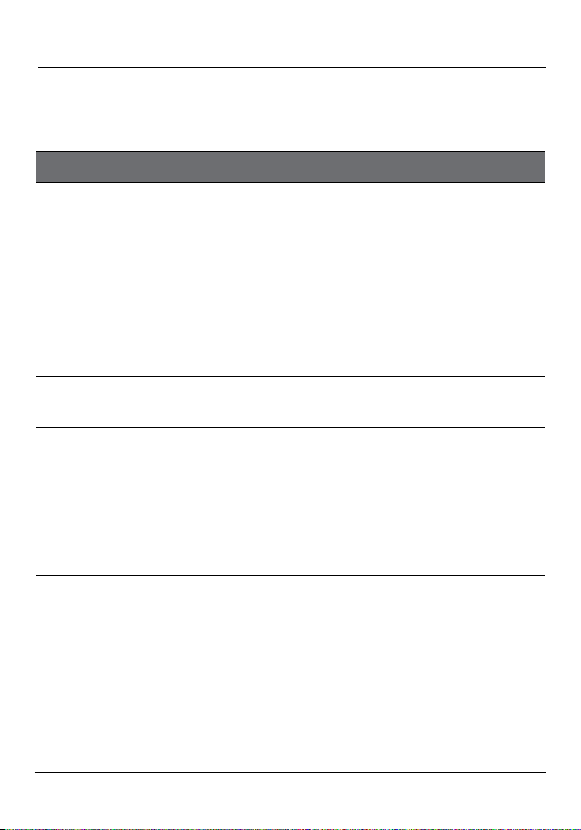
Parameter Setting of PHU 3400(X)-110
Cal preset values
Note: HOLD mode active
Cal Preset Values
Parameter Choices (default in bold print)
• Calimatic buffer Knick: 2.00 4.01 7.00 9.21
Merck/Riedel: 2.00 4.00 7.00 9.00 12.00
DIN 19267: 1.09 4.65 6.79 9.23 12.75
NIST standard: 4.006 6.865 9.180
NIST technical: 1.68 4.00 7.00 10.01 12.46
Hamilton: 2.00 4.01 7.00 10.01 12.00
Kraft: 2.00 4.00 7.00 9.00 11.00
Hamilton A: 2.00 4.01 7.00 9.00 11.00
Hamilton B: 2.00 4.01 6.00 9.00 11.00
Hach: 4.01 7.00 10.00
Ciba: 2.06 4.00 7.00 10.00
Reagecon: 2.00 4.00 7.00 9.00 12.00
• Drift check Fine: 1.2 mV/min (Abort after 180 sec)
Standard: 2.4 mV/min (Abort after 120 sec)
Coarse: 3.75 mV/min (Abort after 90 sec)
• Calibration timer
Monitoring Auto, Off, Individual
Calibration timer 0168h Entry with “Individual”; Off = 0000
Adaptive cal timer Off, On
• Cal tolerance band Tolerance band check: Off, On
Tolerance Zero +00.20 pH (entry)
Tolerance Slope +002.0 mV/pH (entry)
• ORP check Test period: 010 s (entry)
Test difference: 0010 mV (entry)
Tolerance Adjustment
(Additional function SW 3400-005)
During calibration this function checks the zero and slope values and
automatically performs an adjustment when the tolerance band is exceeded.
The parameters are stored in the tolerance band recorder (Diagnostics menu).
Control via Probe Controller
(Parameter setting / Probe control / Cal preset values / Cal mode / Adjustment)
With “Cal tolerance band check” switched on, data are only taken over when
they exceed the limits defined by the tolerance band.
38
Page 39
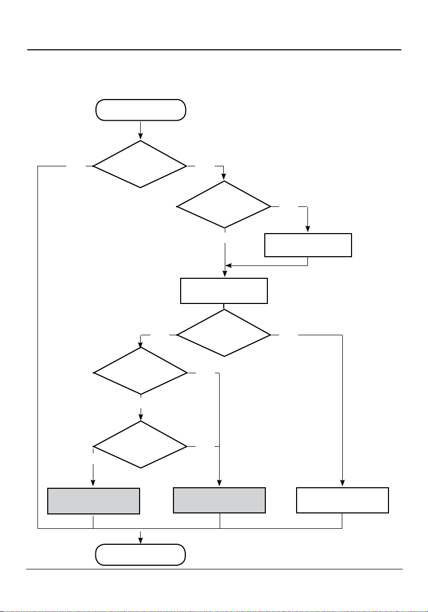
SW 3400-005: Tolerance Adjustment
Program Flow
Start tolerance band
No
Calibration /
Adjustment ?
Zero > Tolerance ?
Slope > Tolerance ?
No
No
Yes
Yes
First Calibration?
No
New entry
Zero + Slope
T-band check?
Yes
Yes
Yes
Erase tolerance band
No
Calibration
Old tolerance band
End of tolerance band
Adjustment
New tolerance band
Manual check
39
Page 40
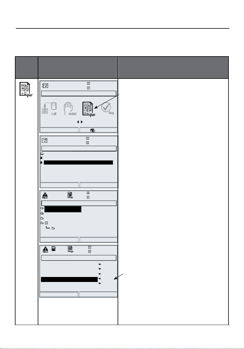
Activating the Cal Tolerance Band
Select menu: Parameter setting/System control/Release of options
Note: The TAN for releasing an additional function is only valid for the
device with the corresponding serial number!
Menu
Display
Menu selection
Select:
Return to meas
Parameter setting
Viewing level
Operating levels
Administrator level
Return
Parameter setting (Administrator)
System control
Module FRONT 3400-011
Module BASE 3400-021
Module PHU 3400-110
Probe control
Return
Release of options (Administrator)
001 KI recorder
002 Buffer sets
003 Adaptive timer
005 Cal tolerance band
006 Current characteristic
Return
[enter]
(All Data) view
(Operation Data) opl
(All Data) adm
7.00 pH
25.6 °C
Lingua
7.00 pH
25.6 °C
7.00 pH
25.6 °C
7.00 pH
25.6 °C
Activating an additional function
Menu selection
Open parameter setting.
From the measuring mode:
Press menu key to select menu.
Select parameter setting using arrow
keys, confirm with enter.
Parameter setting
Select Administrator level
using arrow keys,
confirm with enter.
Enter passcode and confirm
(Passcode as delivered: 1989).
Select system control
using arrow keys,
confirm with enter.
Then select Release of options
using arrow keys,
confirm with enter.
Release of options
Select the additional function to be
Inactive
Inactive
Inactive
Active
Inactive
released (“Cal tolerance band”).
Set option to “active”. Enter the TAN
at the prompt. (Note: The TAN is only
valid for the device with the corresponding serial number, see previous
page.) The option is available after the
TAN has been entered.
40
Page 41
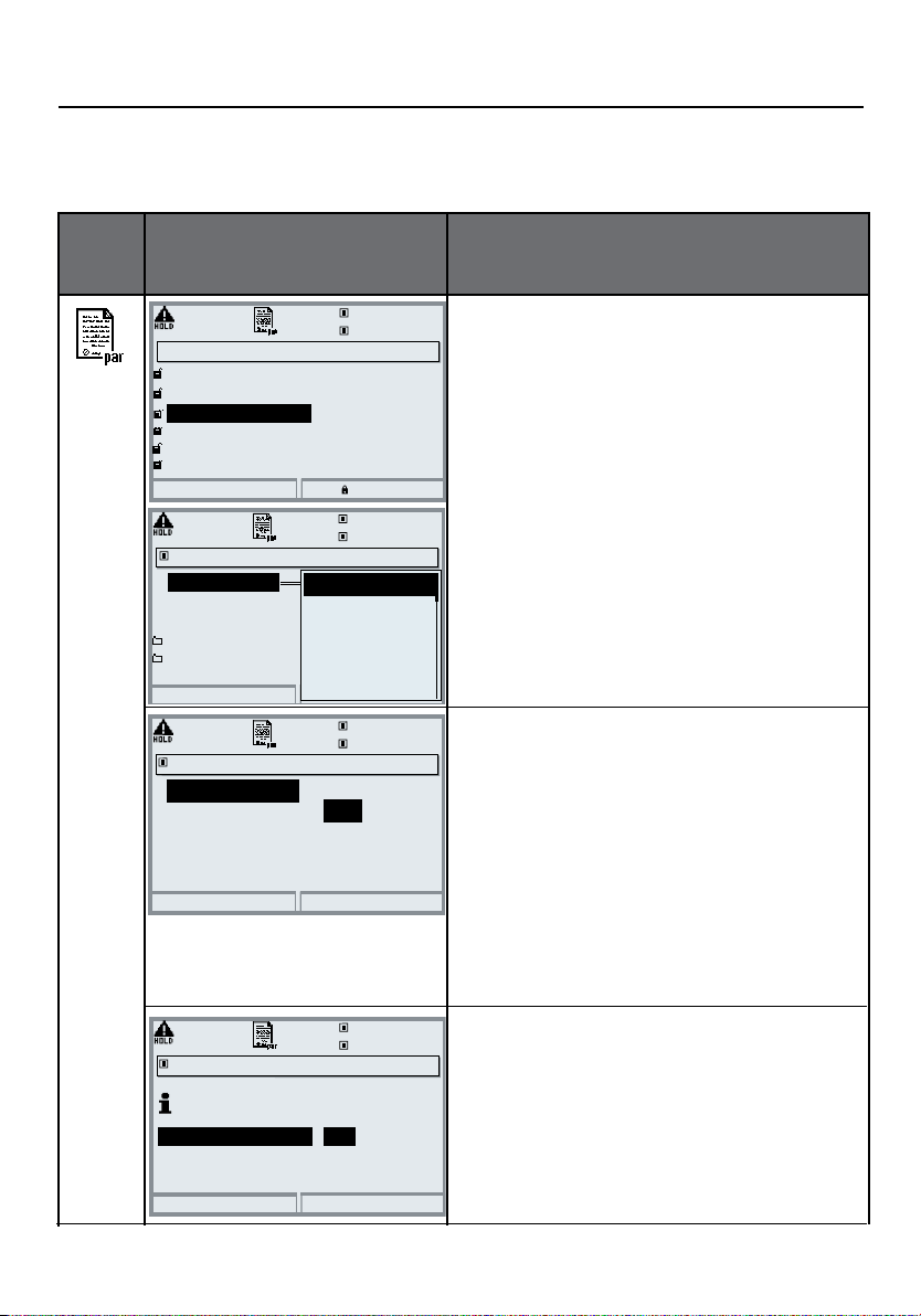
Parameter Setting of PHU 3400(X)-110
Cal preset values: Calimatic buffer, Cal timer, Cal tolerance band
Note: HOLD mode active
Menu Display Cal preset values
7.00 pH
Module PHU 3400-110 (Administrator)
Input filter
Sensor data
Cal preset values
TC process medium
ORP/rH value
Delta function
Return
Cal preset values (Administrator)
Calimatic buffer
Knick 2.00 4.01
Drift check
Calibration timer
Cal tolerance band
Abort
Cal timer (Administrator)
Calibration timer
Adaptive cal timer
Return
20.1 °C
Block
7.00 pH
20.1 °C
Knick
Mettler-Toledo
Merck/Riedel
DIN 19267
NIST standard
NIST technical
Hamilton
7.00 pH
20.1 °C
168 h
Off
On
Calimatic buffer
For automatic calibration, you must
define the buffer set you want to use.
For calibration, you must then use
buffer solutions from this buffer set.
The order does not matter.
The selected buffer set with the
nominal values of the individual buffer
solutions is displayed in gray.
The “Calimatic buffer” menu shows all
buffer sets available.
Select buffer set with enter.
Calibration timer
Entry of the time interval until the
next due calibration.
Adaptive calibration timer
Automatically reduces the time until
the next due calibration when the
electrode is exposed to high stress
(temperature, extreme pH values).
Cal tolerance band (Administrator)
Calibration data taken over when
tolerance band exceeded
Tolerance band check
Tolerance Zero
Tolerance Slope
Return
On
7.00 pH
20.1 °C
Off
+00.20 pH
002.0 mV/pH
Tolerance adjustment
If the measured value leaves the tolerance band specified here for zero
and slope, an adjustment is automatically performed during calibration.
41
Page 42

Parameter Setting of PHU 3400(X)-110
TC process medium, ORP/rH value, delta function:
Default settings and selection range
Parameter Choices (default in bold print)
• TC process medium Off, linear, ultrapure water, table
Linear: enter temperature factor +XX.XX %/K
• ORP/rH value
Reference electrode Ag/AgCl, KCl 1 mol/l
Ag/AgCl,KCI 3mol/l
Hg, Tl/TlCl, KCl 3.3 mol/l
Hg/Hg2SO4, K2SO4 sat
ORP conversion to SHE No, Yes
Calculate rH with factor No, entry of factor
• Delta function Off, pH, mV+ORP or rH: entry of delta value
Temperature compensation of process medium
Linear temperature compensation, reference temp fixed at 25 °C
pH(25 °C) = pHM + TC/100 % (25 °C - TM)
pH
(25 °C)
= pH value compensated to 25 °C
pHM = Measured pH value (temp-corrected)
TC = Temperature factor [%/K]
T
M
= Measured temperature [° C]
42
Page 43
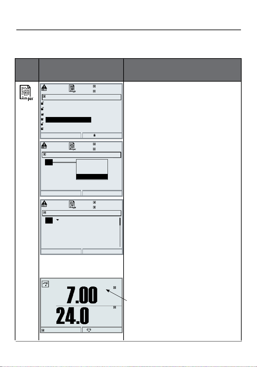
Parameter Setting of PHU 3400(X)-110
TC process medium
Note: HOLD mode active
Menu Display TC process medium
7.00 pH
Module PHU 3400-110 (Administrator)
Input filter
Sensor data
Cal preset values
TC process medium
ORP/rH value
Delta function
Return
TC process medium (Administrator)
TC
Return
TC process medium (Administrator)
TC
TC at 00°C:
TC at 05°C:
TC at 10°C:
TC at 15°C:
TC at 20°C:
Abort
Table
Off
linear
Ultrapure water
Table
+00.00%
+00.00%
+00.00%
+00.00%
+00.00%
24.0 °C
Block
7.00 pH
24.0 °C
OK
7.00 pH
24.0 °C
Info
TC process medium
You can choose from:
• Linear (entry of TC coefficient)
• Ultrapure water
• Table
When measuring media with a known
temperature behavior, the output pH
value can be corrected using a table.
TC can be entered in 5 °C steps for
temperatures between 0 and +95°C.
Then, the output pH value is corrected by the corresponding TC value
depending on the measuring temperature. Intermediate values are linearly
interpolated. In the case of lower or
higher temperatures (< 0 °C or
> +95 °C), the last table value is used
for calculation.
If the delta function has been activated (see Pg 42) simultaneously
with temperature compensation, the
temperature is compensated first and
then the delta value is subtracted.
Outp I1 5.70 mA
TC
pH
°C
Favorites menu
When the TC correction for process
medium is switched on, ”TC” appears
in the display in measuring mode.
43
Page 44
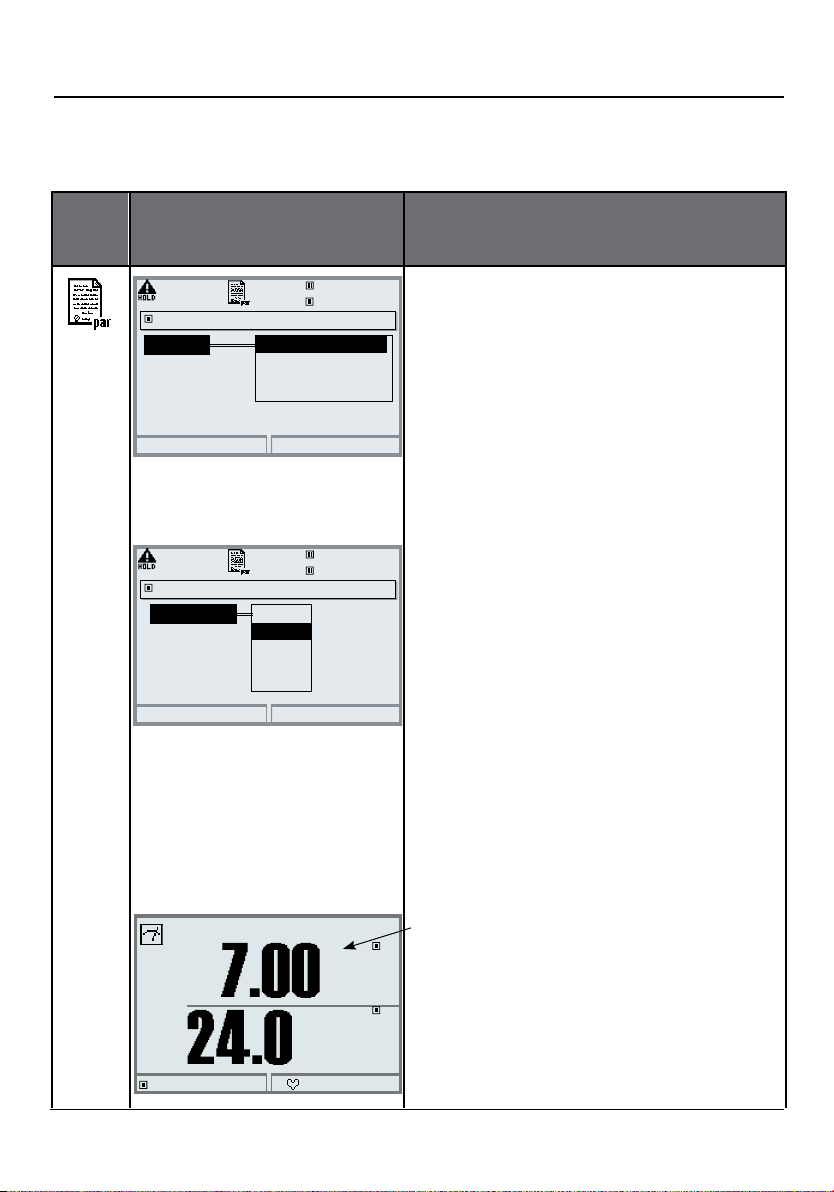
Parameter Setting of PHU 3400(X)-110
ORP/rH value, delta function
Note: HOLD mode active
Menu Display ORP/rH value, delta function
ORP/rH value (Administrator)
Ref el
ORP conversion
rH with factor
Abort
Delta function (Administrator)
Delta function
Delta value
Return
Ag/AgCl, KCl 1m
Ag/AgCl, KCl 3m
Hg,Ti/TiCl,KCl 3.5m
Hg/Hg2SO4,K2SO4 sat
Off
pH
mV
ORP
rH
7.00 pH
20.1 °C
OK
7.00 pH
20.1 °C
OK
ORP/rH value
• Select type of reference electrode:
Ag/AgCl, KCl 1 mol/l (silver/silver chloride)
Ag/AgCl, KCl 3 mol/l (silver/silver chloride)
Hg, Tl/TlCl, KCl 3.3 mol/l (Thalamid)
Hg/Hg2SO4, K2SO4 saturated (mercury sulfate)
• ORP conversion to SHE
• Calculate rH with factor
Delta function
When a delta value is entered, the
system calculates the difference.
Output value = measured value – delta value
The output value controls all outputs
and is shown on the display. When
the delta function has been activated
simultaneously with temperature
compensation, the temperature is
compensated first and then the delta
value is subtracted.
44
Outp I1 5.70 mA
∆
pH
°C
Favorites menu
When delta function is switched
on, “∆” appears in the display in
measuring mode.
Page 45
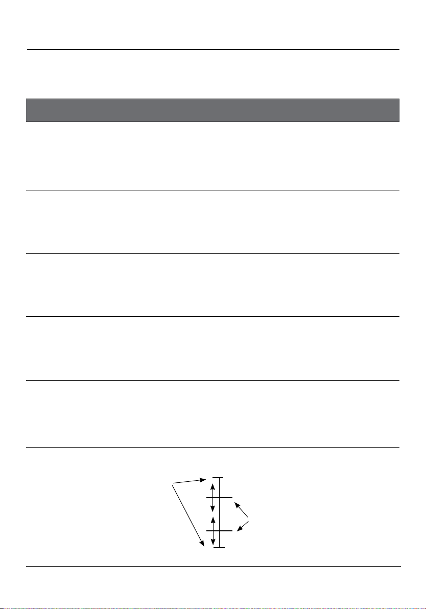
Parameter Setting of PHU 3400(X)-110
Messages: Default settings and selection range
Parameter Choices (default in bold print)
• pH value Off, device limits max., Variable limits:
- Failure Limit LO
- Warning Limit LO
- Warning Limit HI
- Failure Limit HI
• ORP value Off, device limits max., Variable limits:
- Failure Limit LO
- Warning Limit LO
- Warning Limit HI
- Failure Limit HI
• rH value Off, device limits max., Variable limits:
- Failure Limit LO
- Warning Limit LO
- Warning Limit HI
- Failure Limit HI
• Temperature Off, device limits max., Variable limits:
- Failure Limit LO
- Warning Limit LO
- Warning Limit HI
- Failure Limit HI
• mV value Off, device limits max., Variable limits:
- Failure Limit LO
- Warning Limit LO
- Warning Limit HI
- Failure Limit HI
Device limits max.
+ 16.00 pH
(maximum range of
measuring module)
Variable limits
(range limits specified)
- 02.00 pH
45
Page 46
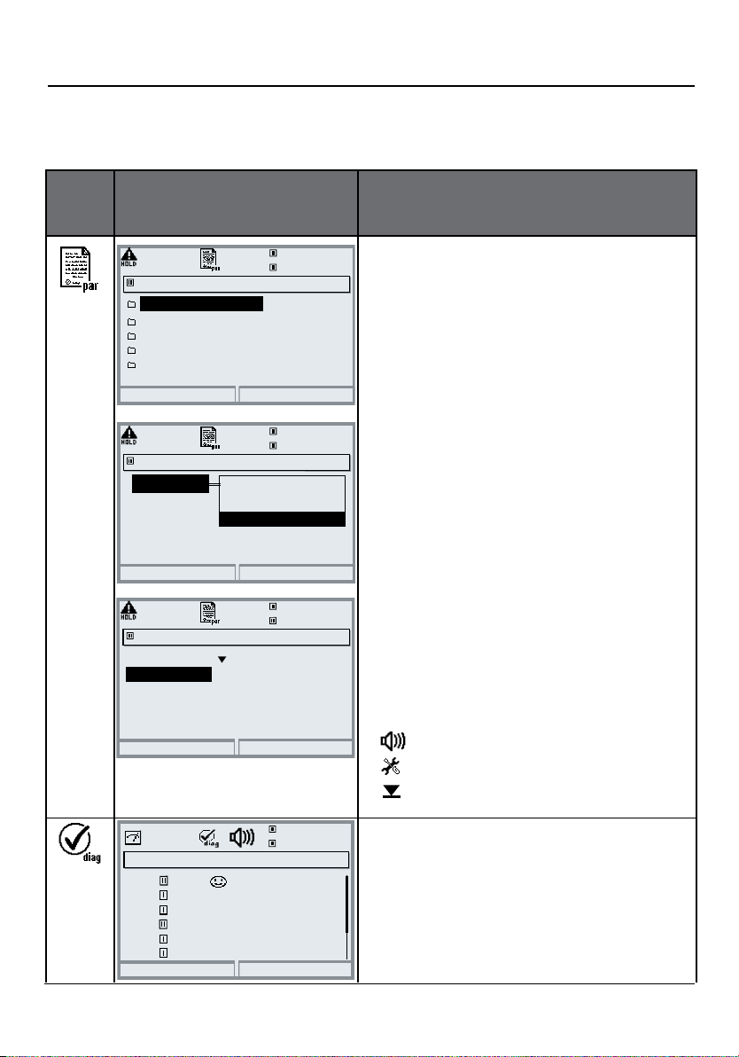
Parameter Setting of PHU 3400(X)-110
Messages
Note: HOLD mode active
Menu Display
Messages (Administrator)
Messages pH value
Messages ORP value
Messages rH value
Messages Temperature
Messages mV value
Return
Messages pH value (Administrator)
Monitoring
Abort
Messages (Administrator)
Monitoring
Failure Limit Lo
Warning Limit Lo
Warning Limit Hi
Failure Limit Hi
Return
7.00 pH
25.6°C
7.00 pH
25.6°C
Off
Device limits max.
Variable limits
OK
7.00 pH
25.6°C
Variable limits
–02.00 pH
–02.00 pH
+16.00 pH
+16.00 pH
OK
Messages
Messages
All parameters determined by the
measuring module can generate
messages.
Device limits max.
Messages are generated when the
process variable (e.g. pH) is outside
the measurement range. The “Failure”
icon is displayed, the NAMUR failure
contact is activated (BASE module,
factory setting: contact K4, N/C
contact).
The current outputs can signal a
22 mA message (user defined).
Variable limits
For the “failure” and “warning” messages you can define upper and lower
limits for message generation.
Message icons
Failure (Failure limit HiHi/LoLo)
Maintenance (Warning limit Hi/Lo)
Limit indication (here: lower range)
46
Message list
D062
Warn
P018
Warn Temp alarm HI
P030
Warn Zero range
D013
Saturation %Air Alarm HI
P210
Fail Wrong ISM sensor
Warn Tolerance band
P092
Return
Sensocheck
7.00 pH
25.6°C
8 messg.
Diagnostics menu
When the “Maintenance” or “Failure”
icons are flashing in the display, you
should call the Diagnostics menu.
The messages are displayed in the
“Message list”.
Page 47

Documenting
Documenting Parameter Setting
You must reproducibly document all parameter settings in the device to
achieve a high level of system and device security according to GLP. For that
purpose, an Excel file is provided (on the CD-ROM shipped with the basic
device) to enter the parameter settings.
The Excel file provides one worksheet for each module with columns for the
following parameters: Factory settings, parameter set A, parameter set B.
Enter your settings as parameter set A or B.
The gray cells in the parameter set B column cannot be modified since they
contain sensor-specific values which cannot be changed by parameter set
switchover. Here, the values listed under parameter set A apply.
47
Page 48
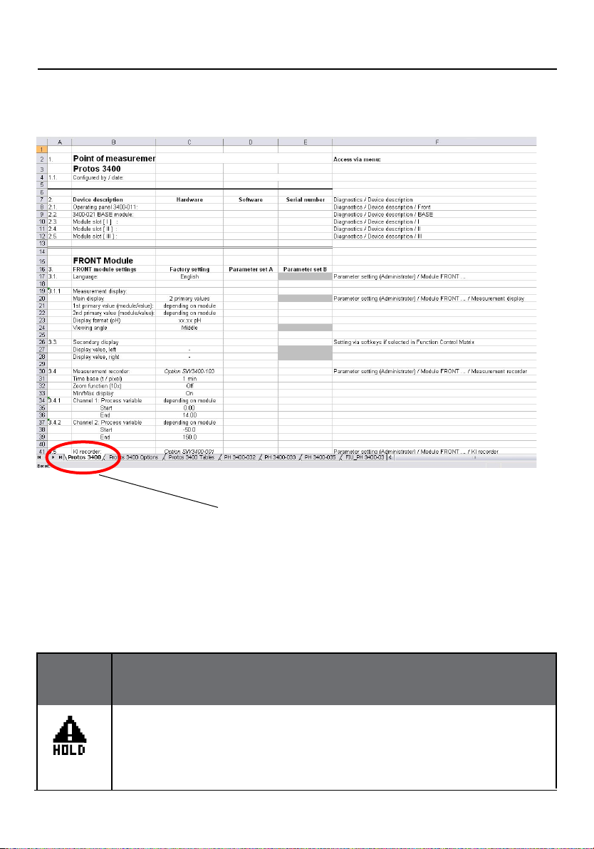
Documenting Parameter Setting
From the application window of the Excel file, select the worksheet for the
module the parameter settings of which you want to document.
Set the parameters of the respective module and enter the selected values in
the corresponding cells of the module worksheet.
NOTICE!
Display
The "HOLD" mode is active during parameter setting.
HOLD. The NAMUR “HOLD” contact (function check) is active (factory setting: Module BASE,
Contact K2, N/O contact). Current output response is user-defined:
• Current meas.: The currently measured value appears at the current output
• Last usable value: The last measured value is held at the current output
• Fixed 22 mA: The output current is at 22 mA
48
Page 49
ProgaLog 3000 Software (Option)
forConfiguration and Documentation
The ProgaLog 3000 software is available for convenient configuration of the
Protos 3400(X) process analysis system. The user interface can be switched to
the Protos display languages English, German, French, Spanish, Italian, Swedish
or Portuguese. The software comes on CD-ROM. It runs under Windows® 8 / 7 /
XP. A card reader for SmartMedia cards is required for transferring the configuration files between PC and Protos 3400.
Configuration with ProgaLog 3000
Insert a SmartMedia card formatted as "memory card" into the analyzer. First,
the configuration data are written to the SmartMedia card. These data can then
be read and edited by the ProgaLog 3000 software.
1. Save the configuration data at the Protos 3400(X)
Parameter setting/System control/Copy configuration.
With “Save“ configuration, the complete device configuration
(except the passcodes) is written on the memory card.
2. Close and remove the SmartMedia card
Select "Maintenance / Close memory card", then remove the card.
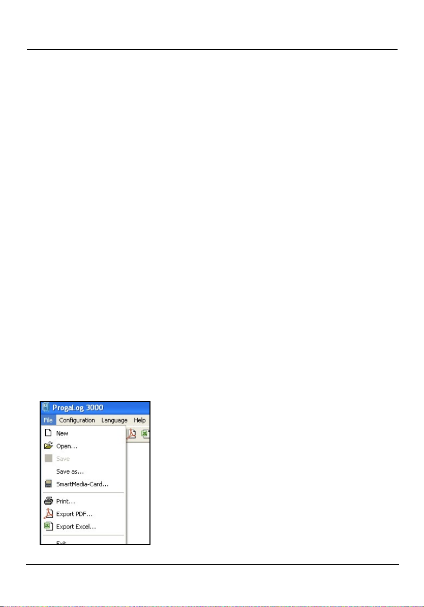
3. Read out SmartMedia card with "ProgaLog 3000"
Open the "File / SmartMediaCard" menu of the
ProgaLog 3000 software to read out the configuration data stored on the SmartMedia card.
Now, you can edit all parameters at your PC.
Save the edited configuration file to the
SmartMedia card. Then, insert the SmartMedia card
into the Protos 3400(X) analyzer.
Fig.: ProgaLog 3000 menu: File
49
Page 50
ProgaLog 3000 Software
for Configuration and Documentation
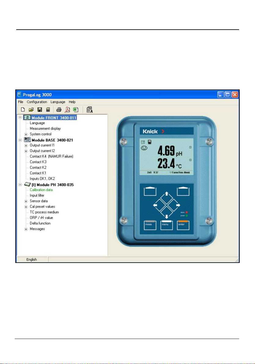
4. Edit configuration data using ProgaLog 3000
When the configuration data have been loaded, the software lists the
connected modules with all available configuration parameters:
Fig.: ProgaLog 3000 configuration data
The parameters are listed according to the modular device structure.
All configuration parameters (except the "Sensor data details", which are determined by digital sensors) can be edited at the PC.
After having finished the configuration, save the data to the SmartMedia card.
50
Page 51
ProgaLog 3000 Software
for Configuration and Documentation
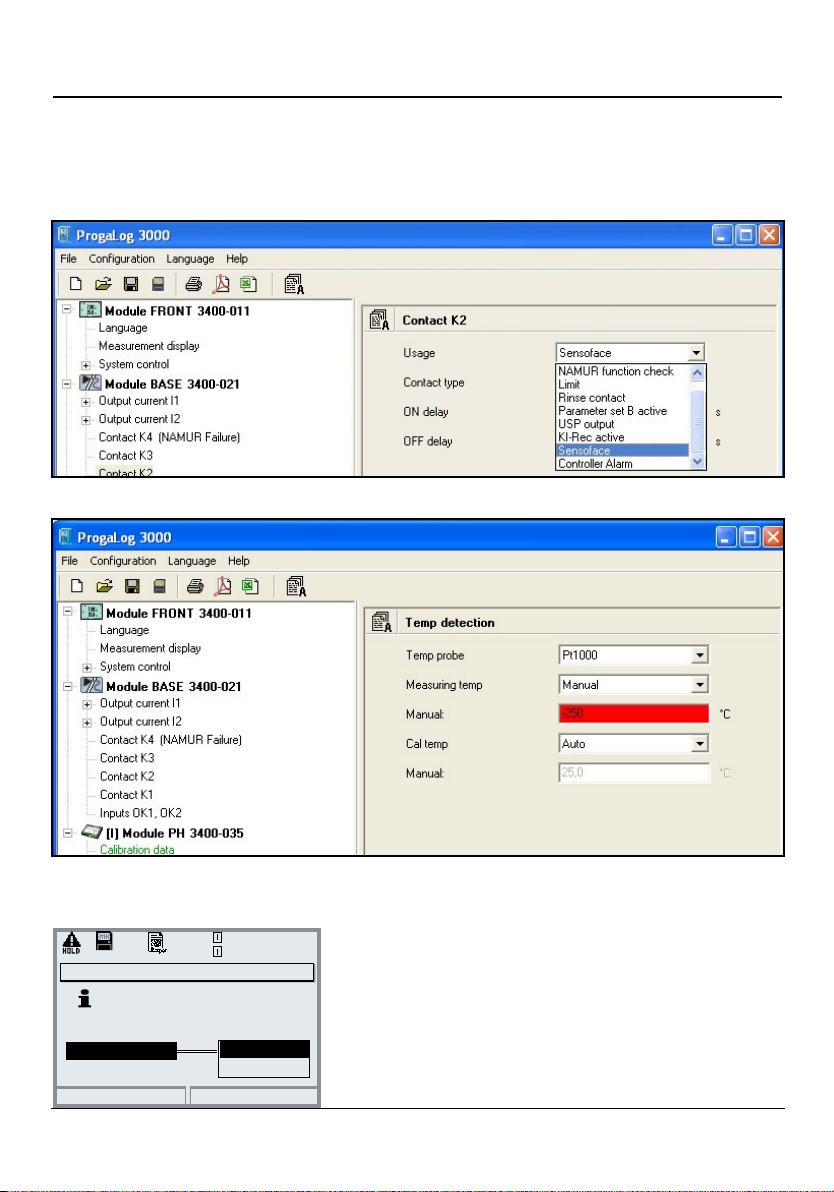
Configuring the parameters, e.g. relay contact usage:
Input errors are indicated by red highlighting:
5. Save the configuration data to SmartMedia card
7.00 pH
Copy configuration (Adminstrator)
Identical module equipment
required for transfer
Configuration
Return
25.6 °C
Load
Save
Save
6. Load the configuration data to the
Protos 3400(X)
Parameter setting / System control /
Copy configuration.
Select “Load configuration” to write the complete
device configuration (except the passcodes) to
the Protos 3400(X).
51
Page 52
ProgaLog 3000 Software
for Configuration and Documentation
Configuration using "ProgaLog 3000"
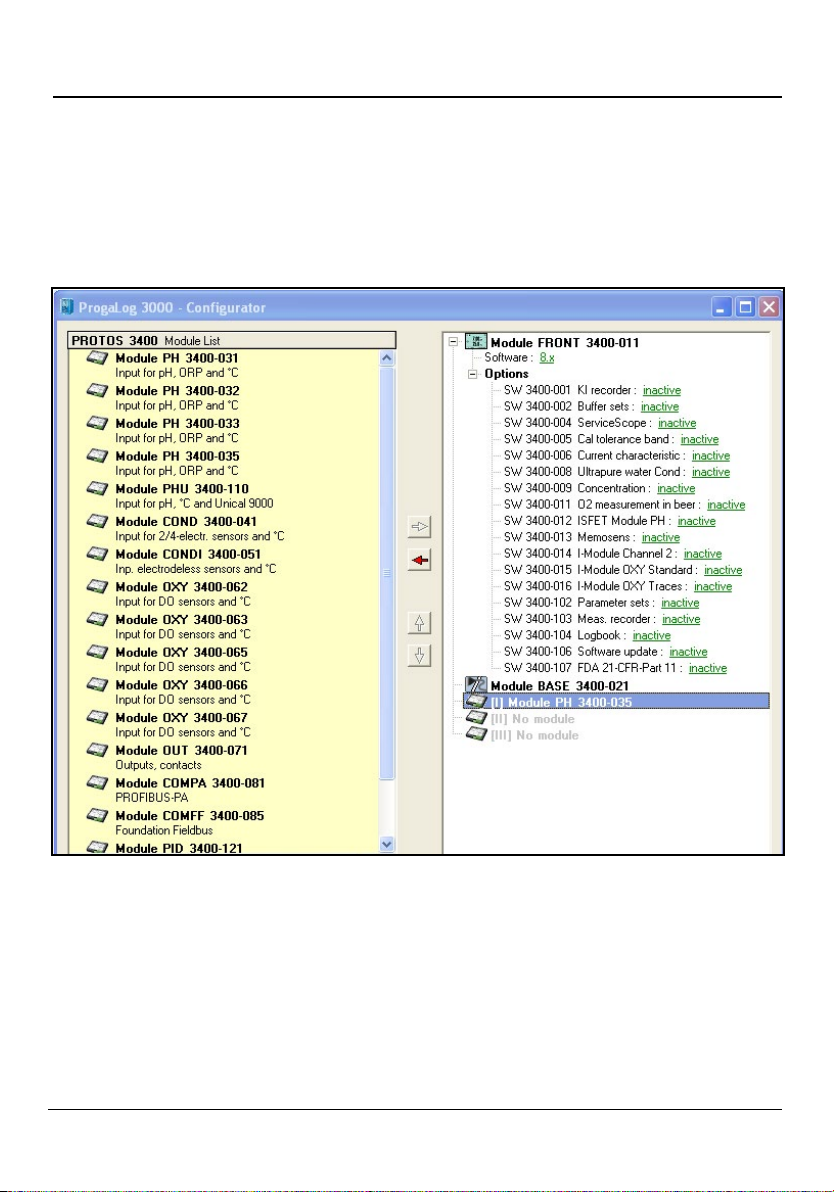
In the "Configurator" menu you can preconfigure a complete Protos 3400(X)
process analysis system with up to 3 modules at your PC.
1. Select your configuration from the modular system components offered in
the left-hand field.
2. Click the right arrow (-->) to add the components or remove components by
clicking (<--).
3. Now configure the parameters for the selected system components.
4. Save the configuration.
You can save the configuration to a memory card that has been pre-
formatted in the Protos 3400(X) and transfer them to analyzers with identical module configurations.
52
Page 53
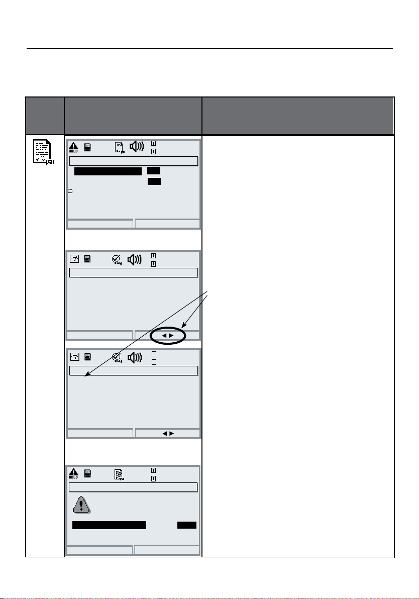
Logbook
Factory setting
Logbook, Factory Setting
Parameter setting/System control/Logbook
Note: HOLD mode
Menu
Display Logbook, Factory setting
Logbook (Administrator)
Log failure
Log warning
Erase logbook
Yes
Yes
7.00 pH
25.6 °C
No
No
Logbook
Select which messages are to be
logged in the logbook.
The last 50 events are recorded with
date and time.
This permits quality management
Return
7.00 pH
Logbook
04/13/10 09:50 Measurement active
04/13/10 09:36 Parameter setting active
04/12/10 17:52 Measurement active
04/12/10 17:44 Parameter setting active
04/12/10 17:40 Wrong passcode
04/12/10 17:04 Measurement active
04/12/10 16:53 Diagnostics active
Return
Logbook
F223 04/13/10 09:50 Diagnostics active
F222 04/13/10 09:36 Parameter setting active
F224 04/12/10 17:52 Measurement active
25.6 °C
7.00 pH
25.6 °C
documentation to ISO 9000 et seq.
The logbook can be called from the
diagnostics menu (Fig.).
Pressing the right softkey displays the
message identifier.
Additional function SW 3400-104:
Extended logbook for recording data
on SmartMedia card (TAN).
Return
Factory setting (Administrator)
The factory setting erases
all your set parameters!
Measuring system
Return
7.00 pH
25.6 °C
Yes
No
Factory Setting
Allows resetting the parameters to
their factory setting. When this menu
is opened, the analyzer displays a
warning (Fig.).
53
Page 54
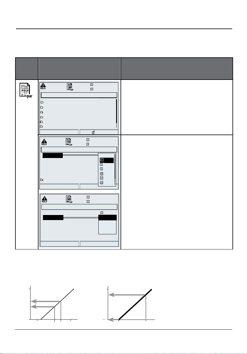
BASE module
Current outputs
Current Outputs, Contacts, OK Inputs
Select menu: Parameter setting/Module BASE
Note: HOLD mode active
Menu
Display
Module BASE (Administrator)
Output current I2
Contact K4 (NAMUR Failure)
Contact K3 (NAMUR maintenance)
Contact K2 (NAMUR HOLD)
Contact K1 (Limit)
Inputs OK1, OK2
Return
Output current I1 (Administrator)
Variable
Curve
Output
Start
End
Behavior during messages
Abort
Output current I1 (Administrator)
Variable
Curve
Output
Start
End
Output filter
Abort
7.00 pH
19.2°C
Block
7.00 pH
19.0 °C
OK
7.00 pH
19.0 °C
OK
Off
pH
°C
rH
S/cm
°C
g/kg
°C
Linear
Trilinear
Function
Table
Parameter setting
BASE module
To configure current output
Configuring a Current Output
• Call up parameter setting
• Call up parameter setting
• Enter passcode
• Enter passcode
• Select “Module BASE”
• Select “Module BASE”
• Select “Output current I1”
• Select “Output current ...”
• Select measured variable
• Select Curve,
e.g. “linear”: The measured variable is
represented by a linear output current curve. The desired range of the
measured variable is specified by the
values for “Start” and “End”.
Assignment of Measured Values: Start (4 mA) and End (20 mA)
Example 1: Range pH 0 - 14 Example 2: Range pH 5 - 7
Output current
20
4
[mA]
0
5 7
14
Advantage: Higher resolution in range of interest
[mA]
20
[pH]
4
5
[pH]
7
54
Page 55
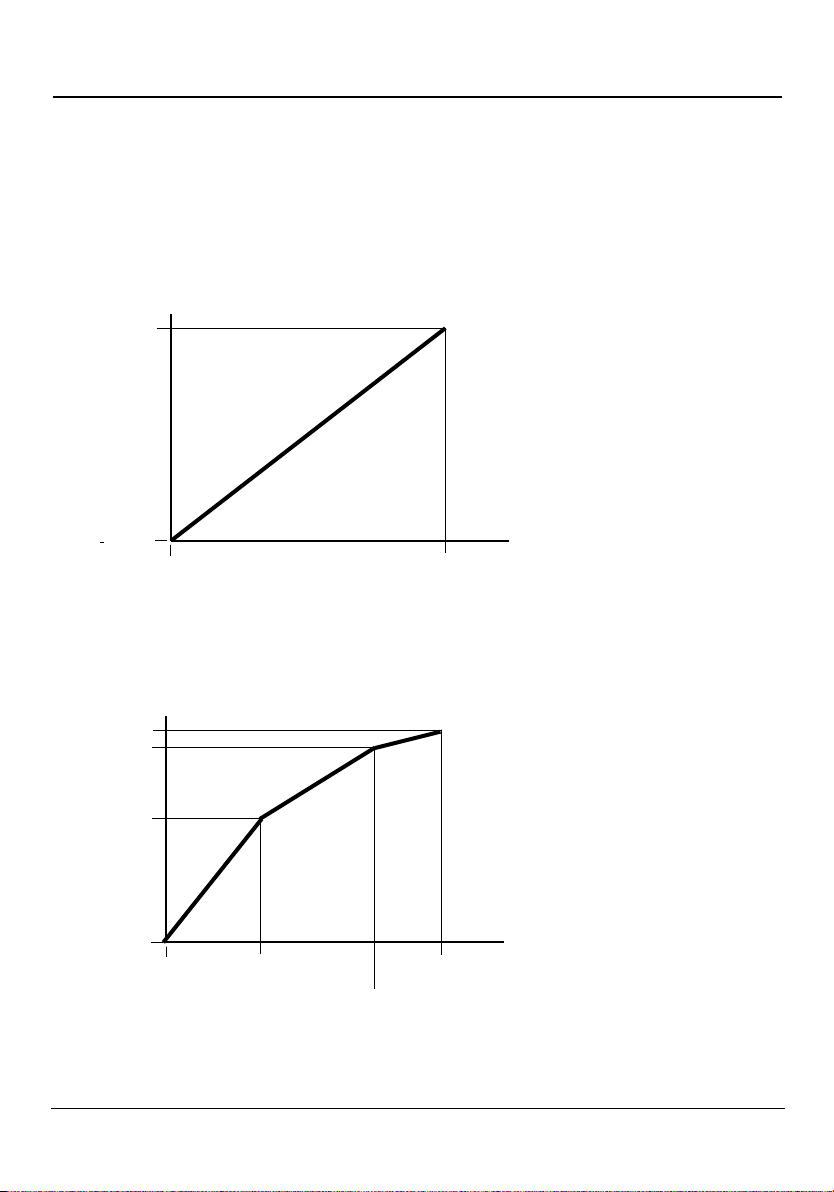
Current Outputs: Characteristics
Select menu: Parameter setting/Module BASE
• Linear characteristic
The process variable is represented by a linear output current curve.
Output current
Y
[%]
100
0
Start
End
X
Process variable
• Trilinear characteristic
Two additional vertices must be entered:
Output current
Y
[%]
100
2nd vertex Y
1st vertex Y
0
Start
1st vertex X
End
2nd vertex X
X
Process variable
• Note: Bilinear characteristic
For a bilinear characteristic, identical parameters are entered for the two
vertices (1st vertex, 2nd vertex).
55
Page 56
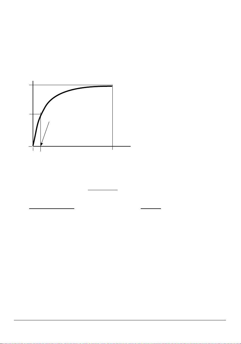
• Function characteristic
Nonlinear output current characteristic: allows measurements over several
decades, e.g. measuring very low values with a high resolution and high
values with a low resolution.
Required: Entering a value for 50 % output current.
Output current
Y
[%]
100
50
Entry for “50 % point”:
e.g.:
10 % of measured value
0
End
Equation
X
Process variable
Output current (4 to 20 mA) = 16 mA + 4 mA
E + S - 2 * X50%
K =
S: Start value at 4 mA
X50%: 50% value at 12 mA (output current range 4 to 20 mA)
E: End value at 20 mA
M: Measured value
Logarithmic output curve over one decade:
S: 10 % of maximum value
X50%: 31.6 % of maximum value
E: Maximum value
Logarithmic output curve over two decades:
S: 1 % of maximum value
X50%: 10 % of maximum value
E: Maximum value
X50% - S
(1+K)x
1+Kx
x =
56
M - S
E - S
Page 57
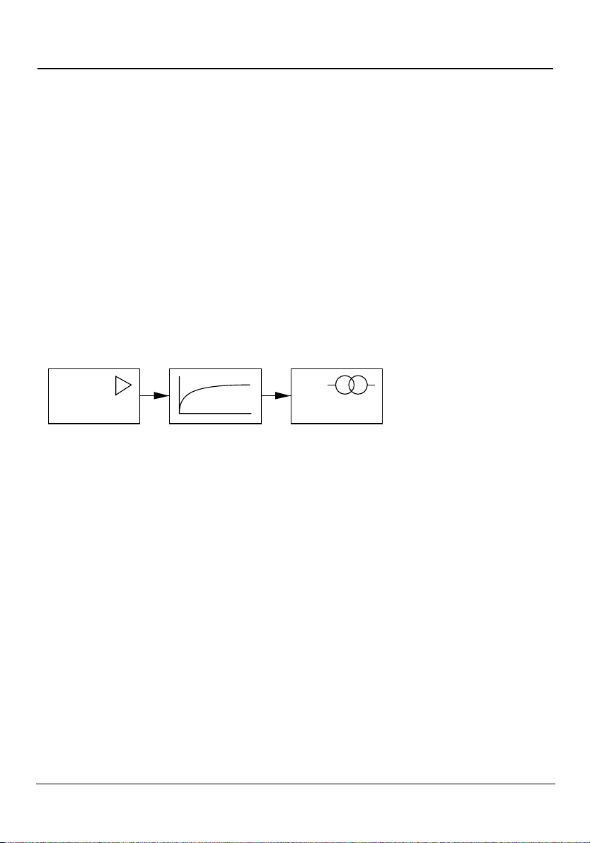
Output Filter
Time interval
Time averaging filter
To smoothen the current output, a low-pass filter with adjustable time interval
can be switched on. When there is a jump at the input (100 %), the output level
is at 63 % after the time interval has been reached.
The time interval can be set from 0 to 120 sec. If the time interval is set to 0 sec,
the current output follows the input.
Note:
The filter only acts on the current output and the current value of the secondary display, not on the measurement display, the limit values or the controller!
Process variable
0 (4) - 20 mA
Time interval 0 ... 120 sec
57
Page 58
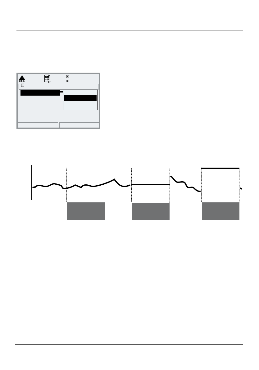
Current outputs: Behavior during messages
NAMUR Signals: Current Outputs
Behavior during messages: HOLD, 22mA signal
Behavior during messages
Depending on the configuration (“Messages”)
the current outputs switch to:
• Currently measured value
• Last measured value (HOLD function)
Behavior during messages
HOLD
22mA message
83.1 % Air
19.0°C
Current meas.
Last usable value
Fixed 22 mA
• Fixed value (22 mA)
In the case of a fault a 22 mA signal can be
Abort
OK
generated for the selected process variable
(1st primary value).
Output current
[mA]
22
4
"Current meas."
HOLD
“Last usable value”
HOLD
“fix (22 mA)”
HOLD
Message when the current range is exceeded
As delivered, the “Maintenance request” (Warn) message is generated when the
current range is exceeded (< 3.8 mA or > 20.5 mA).
This setting can be changed in the Parameter setting menu of the respective
measuring module at “Messages”.
To generate a “Failure” message, the limit value monitoring must be set to
“Variable limits”:
Parameter setting - <measuring module> - Messages - Variable limits -
Failure limit ...
Enter the same values for the failure limits as for the current output:
Parameter setting - Module BASE - Output current - Variable Start / End.
58
Page 59
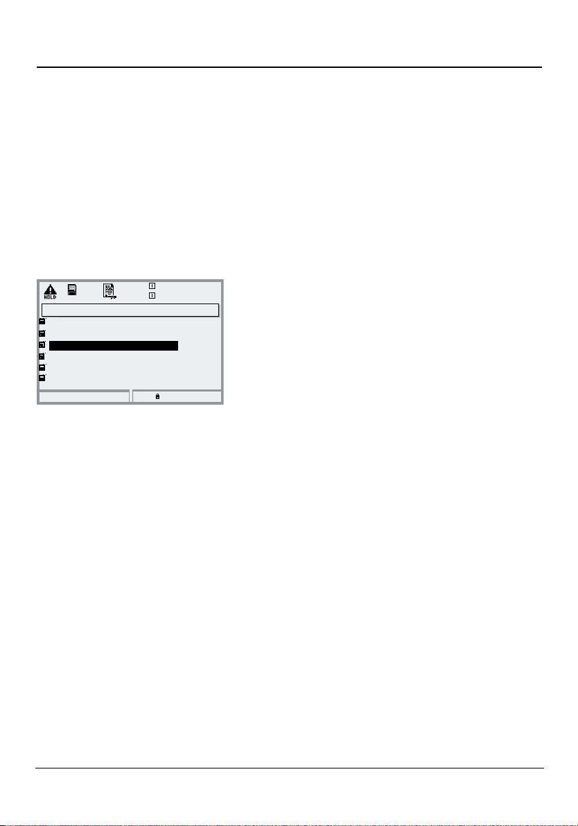
NAMUR Signals: Relay Contacts
Failure, maintenance request, HOLD (function check)
As delivered, the floating relay outputs of the BASE module are assigned to the
NAMUR signals:
Failure Contact K4, normally closed
(signaling current failure)
Maintenance request Contact K3, normally open contact
HOLD Contact K2, normally open contact
NAMUR signals: Factory setting of contacts
• Select parameter setting
• Administrator level
• Select “Module BASE” (Fig.)
You can define a delay time for “Maintenance request”
and “Failure”, resp.
If an alarm message is released, the contact will only be
activated after expiry of this delay time.
Module BASE (Administrator)
Output current I1
Output current I2
Contact K4
Contact K3
Contact K2
Contact K1
(NAMUR failure)
(NAMUR maintenance)
(NAMUR HOLD)
(Limit)
Return
7.00 pH
19.0°C
Block
Failure is active
when a value has exceeded (or fallen below, resp.) a preset ”Failure Limit Hi”
or ”Failure Limit Lo”, when the measured value is out of range, or in the event
of other failure messages. That means that the equipment no longer operates
properly or that process parameters have reached a critical value.
Failure is disabled during "HOLD" (Function check).
Maintenance request is active
when a value has exceeded (or fallen below, resp.) a preset "Warning Limit Hi"
or "Warning Limit Lo", or when other warning messages have been activated.
That means that the equipment is still operating properly but should be serviced, or that process parameters have reached a value requiring intervention.
Warning is disabled during "HOLD" (function check).
HOLD is active:
• during calibration
• during maintenance (current source, meas. point maintenance)
• during parameter setting at the Operator level and the Administrator level
• during an automatic rinsing cycle
59
Page 60
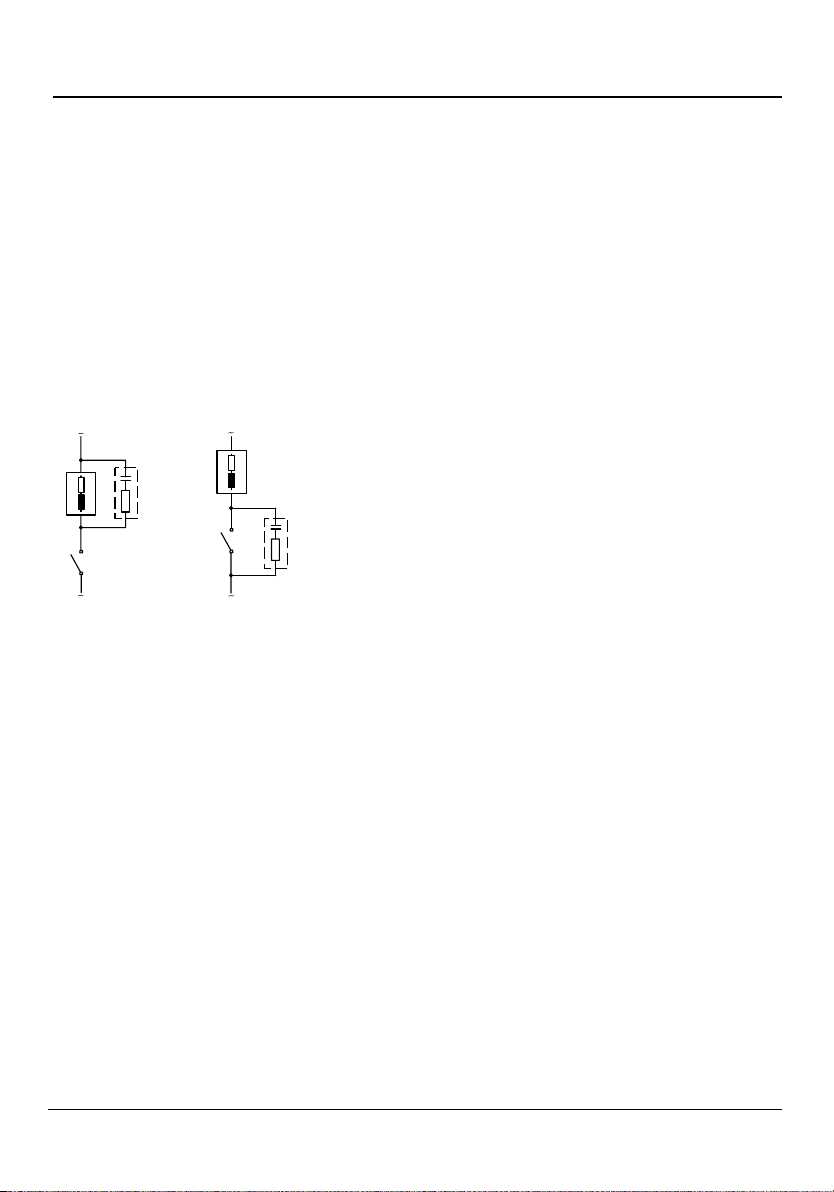
Relay Contacts: Protective Wiring
Protective wiring of relay contacts
Relay contacts are subject to electrical erosion. Especially with inductive and
capacitive loads, the service life of the contacts will be reduced. For suppression of sparks and arcing, components such as RC combinations, nonlinear
resistors, series resistors and diodes should be used.
Typical AC applications
1
1
3
2
3
with inductive load
1 Load
2 RC combination, e.g. RIFA PMR 209
Typical RC combinations
2
e.g.
capacitor 0.1 µF
resistor 100 ohms / 1 W
3 Contact
Caution!
Make sure that the maximum ratings of the relay contacts are not exceeded
even during switching!
Information concerning relay contacts
As delivered, the relay contacts are suitable for low signal currents (down to
approx. 1 mA). If currents above approx. 100 mA are switched, the gold plating
is destroyed during the switching process. After that, the contacts will not
reliably switch low currents.
60
Page 61
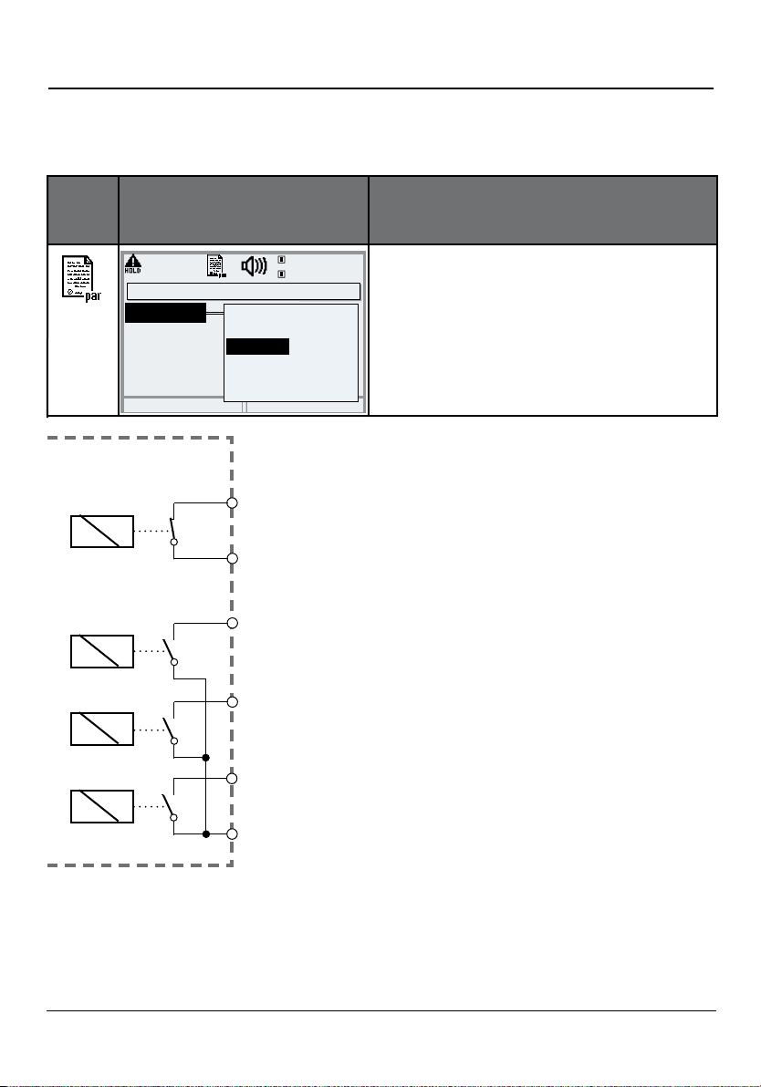
Relay contacts
Relay Contacts
Parameter setting/Module BASE/Relay contacts
Menu
Display Setting the relay contacts
Usage
Variable
Limit value
Hysteresis
Effective direction
Contact type
Module BASE
Alarm (K4)
K1
K2
Contact K1 (Administrator)
NAMUR maintenance
NAMUR HOLD
Limit value
Rinse contact
Parameter set B active
Return
USP output
7.00pH
19.2°C
Relay Contacts, Usage
• Open parameter setting
• Enter passcode
• Select “Module BASE”
• Select “Contact ...”
• “Usage” (Fig.)
The BASE module provides 4 relay contacts
(max. AC/DC rating 30 V / 3 A each).
Contact K4 is provided for failure message. The
switching behavior (normally open or normally
closed), as well as a switch-on or switch-off
delay can be defined.
Default settings of the user-definable relay
contacts of the BASE module:
K3: NAMUR maintenance request
K2: NAMUR HOLD (function check)
K1: Limit value
K3
Contact assignment:
See terminal plate of
BASE module
K1-K3 are user definable (“Usage”):
• NAMUR maintenance
• NAMUR HOLD
• Limit value
• Rinse contact
• Parameter set B active
• USP output (COND module only)
• KI rec. active
• Sensoface
• Alarm control
61
Page 62

Relay Contacts: Sensoface Messages
Parameter setting/Module BASE/Relay contacts/Usage/Sensoface
Menu
Display Parameter setting (Sensoface)
Module BASE (Administrator)
Output current I1
Output current I2
Contact K4
Contact K3
Contact K2
Contact K1
Contact K1 (Administrator)
Usage
Variable
Limit value
Hysteresis
Effective direction
Contact type
Return
Return
(NAMUR Failure)
(NAMUR maintenance)
( Sensoface)
( Sensoface)
NAMUR maintenance
NAMUR HOLD
Limit value
Sensoface
Parameter set B active
USP output
7.00 pH
19.0°C
Block
7.00 pH
19.2°C
Assign Sensoface messages to relay
contacts
When more than one measuring
module is used, the Sensoface messages of the modules can be assigned
to different contacts.
Relay contacts, usage
• Open parameter setting
• Enter passcode
• Select “Module BASE”
• Select contact e.g. K1)
• Assign Sensoface message of
desired measuring module to
selected relay contact
Set contact parameters
• (e.g. "N/O")
• Set ON / OFF delay.
Contact K1 (Administrator)
Usage
Contact type
ON delay
OFF delay
7.00pH
19.2°C
Sensoface
N/O
0010 s
0010 s
62
Return
Page 63
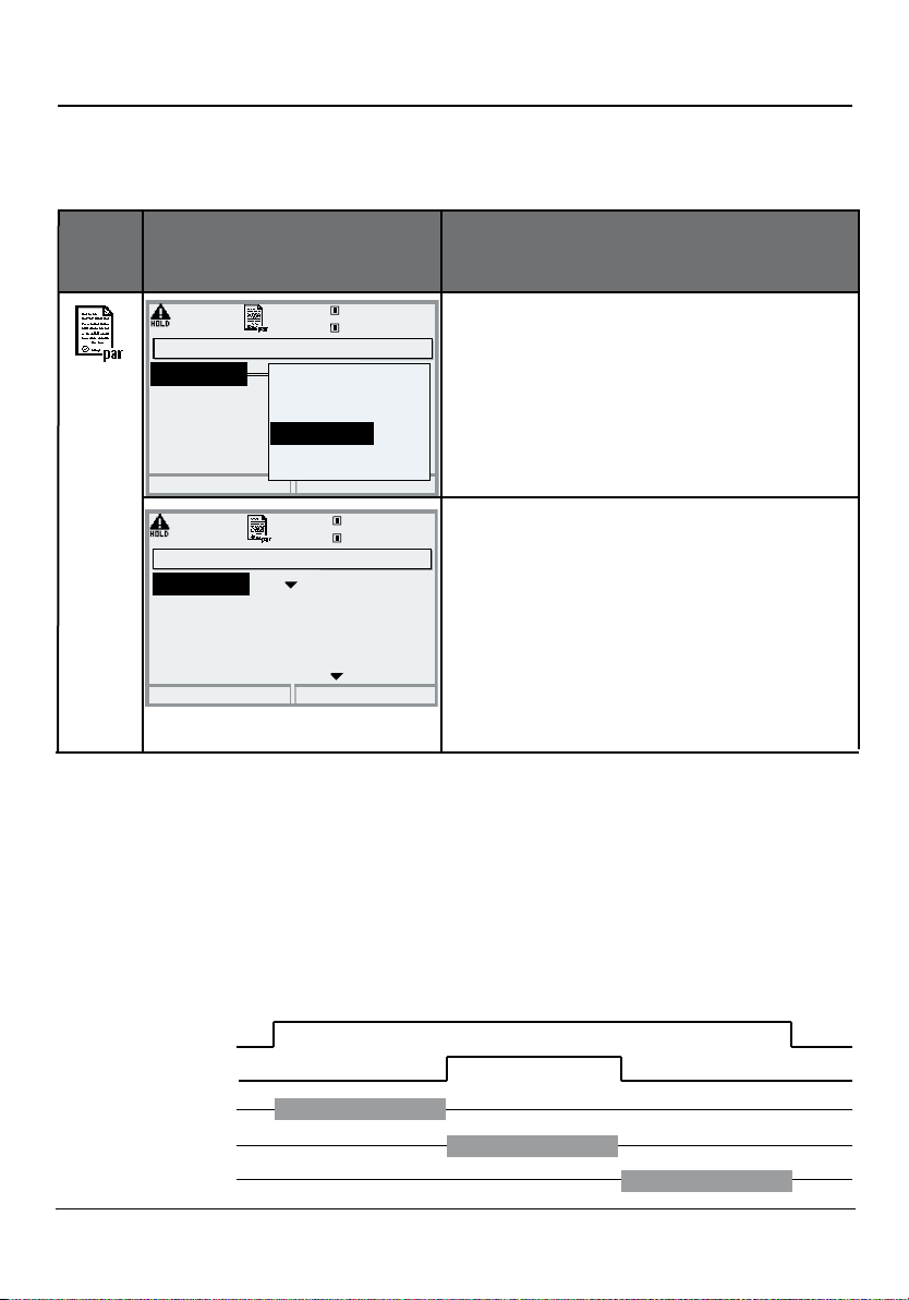
Rinse contact
Rinse Contact
Parameter setting/Module BASE/Relay contacts/Usage/Rinse contact
Menu
Display Configuring the rinse contact
Contact K1 (Administrator)
Usage
Variable
Limit value
Hysteresis
Effective direction
Contact type
Return
Contact K1 (Administrator)
Usage
Rinse interval
Rinsing lead time
Rinse duration
Measurement lead time
Contact type
Return
NAMUR maintenance
NAMUR HOLD
Limit value
Rinse contact
Parameter set B active
USP output
7.00 pH
19.2°C
7.00pH
19.2°C
Rinse contact
000.0 h
0010 s
0016 s
0010 s
N/O
Relay contacts, usage
• Open parameter setting
• Enter passcode
• Select “Module BASE”
• Select contact e.g. K1)
• “Rinse contact” (Fig.)
Set rinse contact parameters
• Set rinse interval
• Set rinse duration
• During the defined "lead time" the
"HOLD" mode is active.
• Select contact type
(e.g. "N/O")
Please note when configuring the "Rinse contact" function
• "HOLD" mode (e.g. during parameter setting) delays the execution of the
"Rinse contact" function.
• Up to 3 rinse functions (contacts K1 ... K3) can be configured independently.
• The individual rinse functions are not synchronized with each other.
Time response
HOLD
Contact Kx
Lead time
Rinse duration
Shut-off delay
63
Page 64
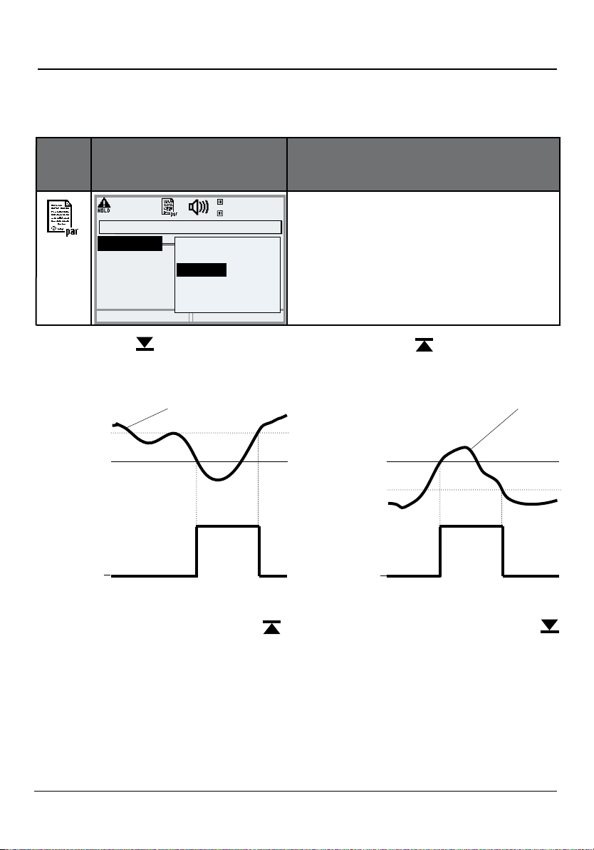
Limit value
Limit Value, Hysteresis, Contact Type
Parameter setting/Module BASE/Relay contacts/Usage
Menu Usage as limit value
7.00 pH
Contact K1 (Administrator)
Usage
Variable
Limit value
Hysteresis
Effective direction
Contact type
Return
NAMUR maintenance
NAMUR HOLD
Limit value
Rinse contact
Parameter set B active
USP output
19.2°C
Limit value
Effective direction min
Signal
Hysteresis +
Limit value
1
Contact
0
Icons in the Measurement Display
Measured value exceeds limit:
Relay output: Limit value
• Open parameter setting
• Enter passcode
• Select “Module BASE”
• Select “Contact ...”
• “Usage: Limit” (Fig.)
Limit value
Effective direction max
Signal
Limit value
Hysteresis -
1
Contact
0
Measured value falls below limit:
Hysteresis
Tolerance band around the limit value, within which the contact is not
actuated. Serves to obtain appropriate switching behavior at the output
and suppress slight fluctuations of the measured variable (Fig.)
Contact type
Specifies whether the active contact is closed (N/O) or open (N/C).
64
Page 65
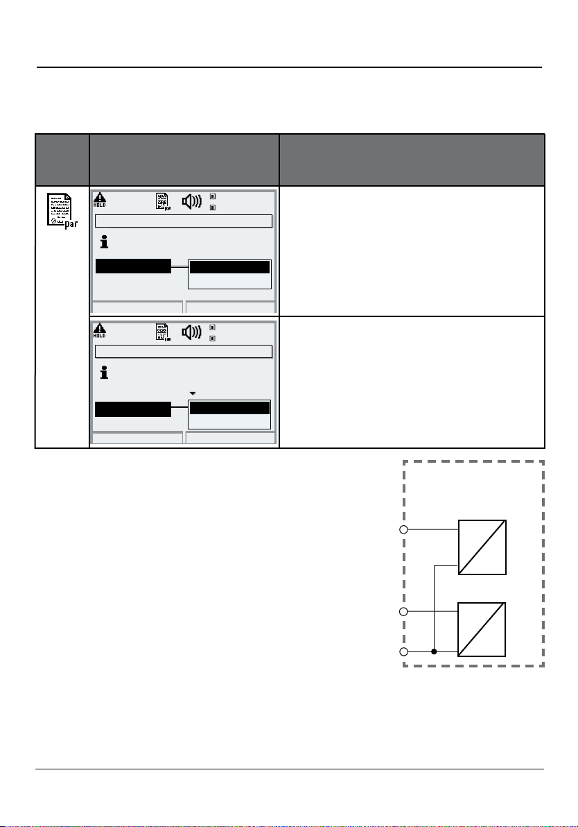
OK1, OK2 Inputs: Specify Level
Parameter setting/Module BASE/Inputs OK1, OK2
Note: HOLD mode (Setting: BASE module)
Menu Display Setting the OK inputs
Inputs OK1, OK2 (Administrator)
For OK2 usage see
“Function control matrix”
OK1 usage
OK2 usage
Return
Inputs OK1, OK2 (Administrator)
For OK2 usage see
“Function control matrix”
OK1 usage
Input OK1
Input OK2
Return
Off
HOLD
HOLD
active 10 ... 30 V
active < 2 V
7.00 pH
19.2°C
7.00 pH
19.2°C
OK
OK1 usage
• Open parameter setting
• Enter passcode
• Select “Module BASE”
• Select “Inputs OK1/OK2”
• Select “OK1 usage”
OK1/OK2 switching level
• Open parameter setting
• Enter passcode
• Select “Module BASE”
• Select “Inputs OK1/OK2”
• Specify active switching level
The BASE module provides 2 digital inputs
(OK1, OK2). The following functions (depending
on the parameter setting) can be started via a
control signal:
• OK1: “Off” or “HOLD”
• OK2: Select: System control / Function
control matrix. (“Off”, “Parameter set A/B”,
“Start KI recorder”)
Module BASE
OK1
OK1
OK2
OK2
You must specify the switching level
for the control signal:
(active 10...30 V or active < 2 V).
OK
65
Page 66
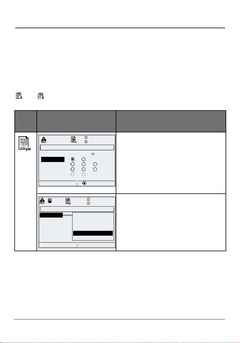
Switching Parameter Sets via OK2
Parameter setting / System control / Function control matrix
Note: HOLD mode (Setting: BASE module)
Parameter Sets
2 complete parameter sets (A, B) can be stored in the analyzer.
You can switch between the parameter sets using the OK2 input.
The currently activated set can be signaled by a relay contact.
An icon in the measurement display shows which parameter set is active:
or
Menu Display
Function control matrix (Administrator)
Input OK2
Left softkey
Right softkey
Profibus DO 2
Return
Contact K3 (Administrator)
Usage
Contact type
ON delay
OFF delay
Abort
83.1 % Air
24.8°C
ParSet KI rec. Fav Unical
NAMUR maintenance!
NAMUR HOLD
Limit value
Rinse contact
Parameter set B active
USP output
– –
Connect
83.1 % Air
24.8°C
OK
Parameter sets
Selecting Parameter Set (A, B) via OK2 Input
• Open parameter setting
• System control
–
–
• Function control matrix
––
• Select “OK2”
• Connect “Parameter set A/B”
Signaling Active Parameter Set via Relay Contact
• Open parameter setting
• BASE module
• Select contact
• Usage: “Parameter set ...”.
Note
The selection has no effect when working on SmartMedia card with
SW 3400-102.
66
Page 67

Setting the Unical 9000(X)
parameters
Unical 9000(X) Parameter Setting
Functional Capabilities
Setting Adjustable parameters Page
• Control Off, Unical 9000, Uniclean 900
• Cal preset values Buffer set as configured in the PHU 3400-110
Cal Buffer 1 Calimatic (automatic) or selection of a buffer
Cal Buffer 2 Calimatic (automatic) or selection of a buffer
Cal mode Adjustment, Calibration
Cal timer program Off, Cleaning, Cal 2pt, Cal 1pt, Parking, User1, User2
• Time control Fixed interval, Week program:
Fixed interval: Select program, interval
Week program: Configuration of program flows
• Program flow Individual adaptation of program steps for:
Cleaning, Cal 2point, Cal 1point, Service, Parking, User 2, User 1
• Installation
External control (DCS) Off, On
DCS inputs (36...39) active 10...30 V or active < 2 V
M/S input (42/43) active 10...30 V or active < 2 V
A/M input (40/41) active 10...30 V or active < 2 V
Output DCS 34 Measuring, Alarm
DCS outputs (31…34) N/O, N/C
• Sensor detection On, Off
• Immersion lock Off, Sensocheck Glass el
• Access manual control Access code required. All valves can be actuated separately.
• Probe Probe type (Ceramat, SensoGate, InTrac, Others)
Move time max. Adjustable; default setting 0015 s
Sealing water On, Off
Cavity rinsing Off, Interval, Continuous
Check interval On, Off (On: Entry: Check after x travels)
Maintenance interval On, Off (On: Entry: Maintenance after x travels)
• Rinse water Monitoring: Off, Process value, Temperature
• Media adapter (I ... III)
(up to 3 metering
pumps)
• Additional media (1...2) Monitoring of medium (Off, Process value, Temperature)
• Start-up Yes, No
• System forecast On, Off
Each:
Medium, Displaced volume, Residual volume,
Monitoring of medium (Off / Process value / Temperature)
Pg 68
Pg 69
Pg 70
Pg 81
Pg 82
Pg 87
Pg 88
67
Page 68
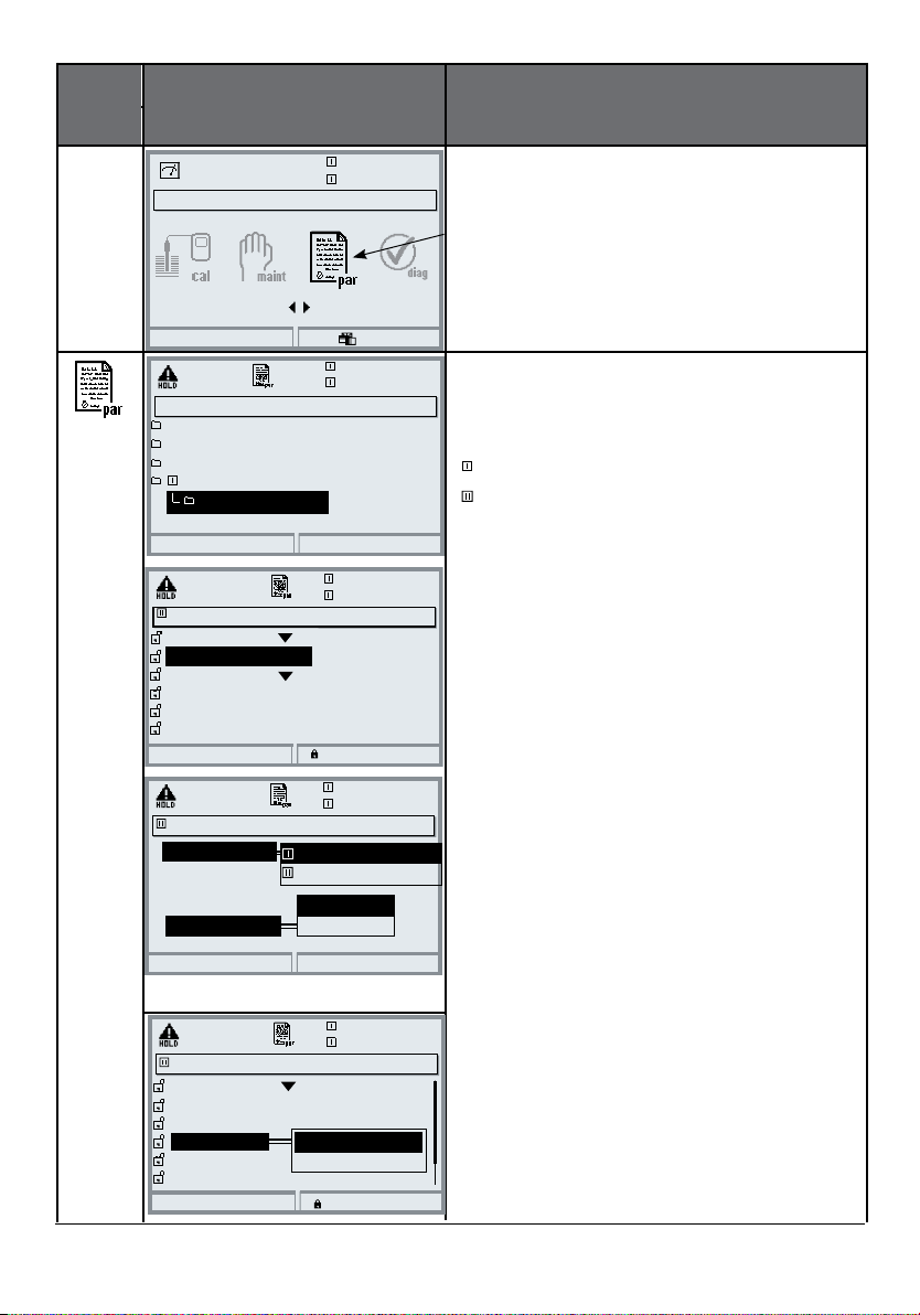
Cal preset values
Time control
Menu Display Unical 9000 parameter setting
7.05 pH
Menu selection
Select:
Return to meas
Parameter setting (Administrator)
System control
Module FRONT 3400-011
Module BASE 3400-021
Module PHU 3400-110
Probe control
Return
Probe control (Administrator)
Control
Cal preset values
Time control
Week program
Program flow
Installation
Return
Cal preset values (Administrator)
Measuring module
Knick 2.00 4.01
Cal Buffer 1
Cal Buffer 2
Cal mode
Return
Module PHU 3400-110
25.6 °C
[enter]
7.05 pH
25.6 °C
OK
7.05 pH
25.6 °C
Unical 9000
Week program
Block
7.05 pH
25.6 °C
Module PH 3400-032
Adjustment
Calibration
Open parameter setting
From the measuring mode:
Press menu key to select menu.
Select parameter setting using arrow
keys, press enter to confirm.
Lingua
Select “Probe control / Unical 9000”.
Icons to assign the measured values
displayed:
specifies module slot I
specifies module slot II
Cal Preset Values Unical 9000
Select pH module: (only if equipped
with more than 1 pH module).
Select cal mode
• Adjustment: The values determined
by a calibration are taken over.
• Calibration: The values determined
by a calibration are logged but not
taken over.
Cal timer program
Starts the selected program after
caltimer expiry.
68
Probe control (Administrator)
Control
Measuring Module
Cal mode
Time control
Program flow
Installation
Return
Unical 9000
Fixed interval
Week program
Block
7.05 pH
25.6 °C
Time Control
• Fixed interval (3): Specify times
(000.0 h ... xxx.x h)
(Please note: 000.1 h = 6 min)
• Week program:
Specify weekday
Page 69
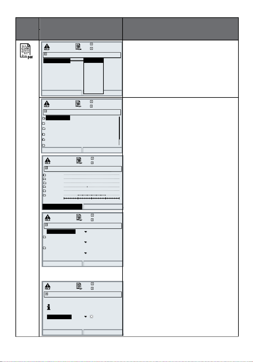
Time control (fixed interval /
week program)
Menu Display Time control configuration
Fixed interval (Administrator)
Program
Interval
Program
Interval
Program
Interval
Abort
Week program (Administrator)
Monday
Tuesday
Wednesday (Today)
Thursday
Friday
Saturday
Return
Monday (Administrator)
User 3
User 2
Parking
Cal 1point
Cal 2point
Clean
0:00 6:00 12:00 18:00 24:00
Return
Monday (Administrator)
01: Program
Start 06:00 End 18:00 Int. 002.0 h
02: Program
Time of start 08:00
03: Program
Return
Off
Clean
Cal 2point
Cal 1point
User 1
User 2
User 3
Clean
Cal 1point
--- End ---
7.05 pH
25.6 °C
OK
7.05 pH
25.6 °C
7.05 pH
25.6 °C
Weekday
7.05 pH
25.6 °C
Time control: Fixed interval
The “Fixed interval” menu allows selection of up to three programs. An individual time interval an be assigned to
each program.
Time control: Week program
In this menu you can View, Edit, and
Copy.
View
shows the configured program
sequences over the day
Edit
allows selection of up to 10 programs
per day and you can choose between
“Individual start” or “Interval” (the program is executed within a start and an
end time at a specified interval).
Copy day (Administrator)
Copy Monday to “Weekday”
Old day is overwritten!
Weekday
Return
7.05 pH
25.6 °C
Copy
allows taking over a configured
program for another weekday.
(Further editing is possible.)
69
Page 70
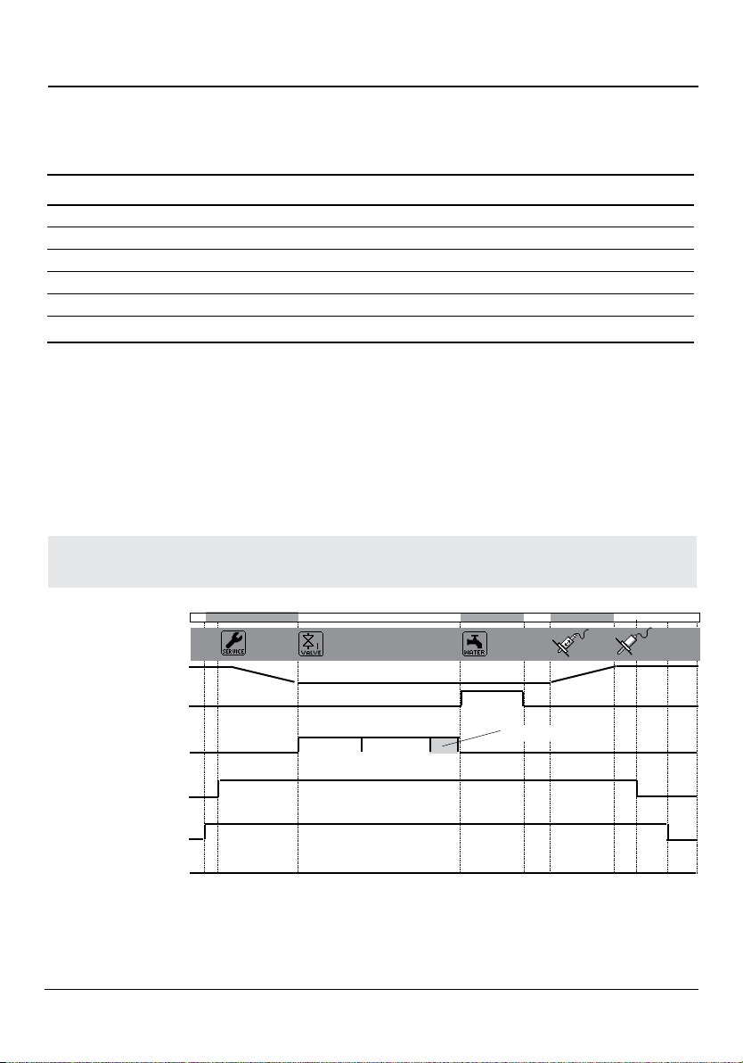
Parameter setting: Program
flows
Cleaning program
Parameter Setting: Program Flows
Cleaning (Continuous), Media Monitoring Off
Display text Time [s]
01: Probe in SERVICE
02: Cleaning agent 0020 s
03: Rinse water ON 0060 s
04: Rinse water OFF 0002 s
05: Probe in MEASURE 0005 s
06: Program end
Cleaning (continuous) can also be started via a DCS input signal at input BIN1
of the Unical 9000 probe controller.
Program step
Message (display)
Probe: Measure
Probe: Service
Rinse water
Cleaning agent
(Pump III)
HOLD
DCS ML3
(Program running)
01 02
Stroke 1
Stroke 2
03 04 05 06
Exposure time
70
[t]
s
Page 71
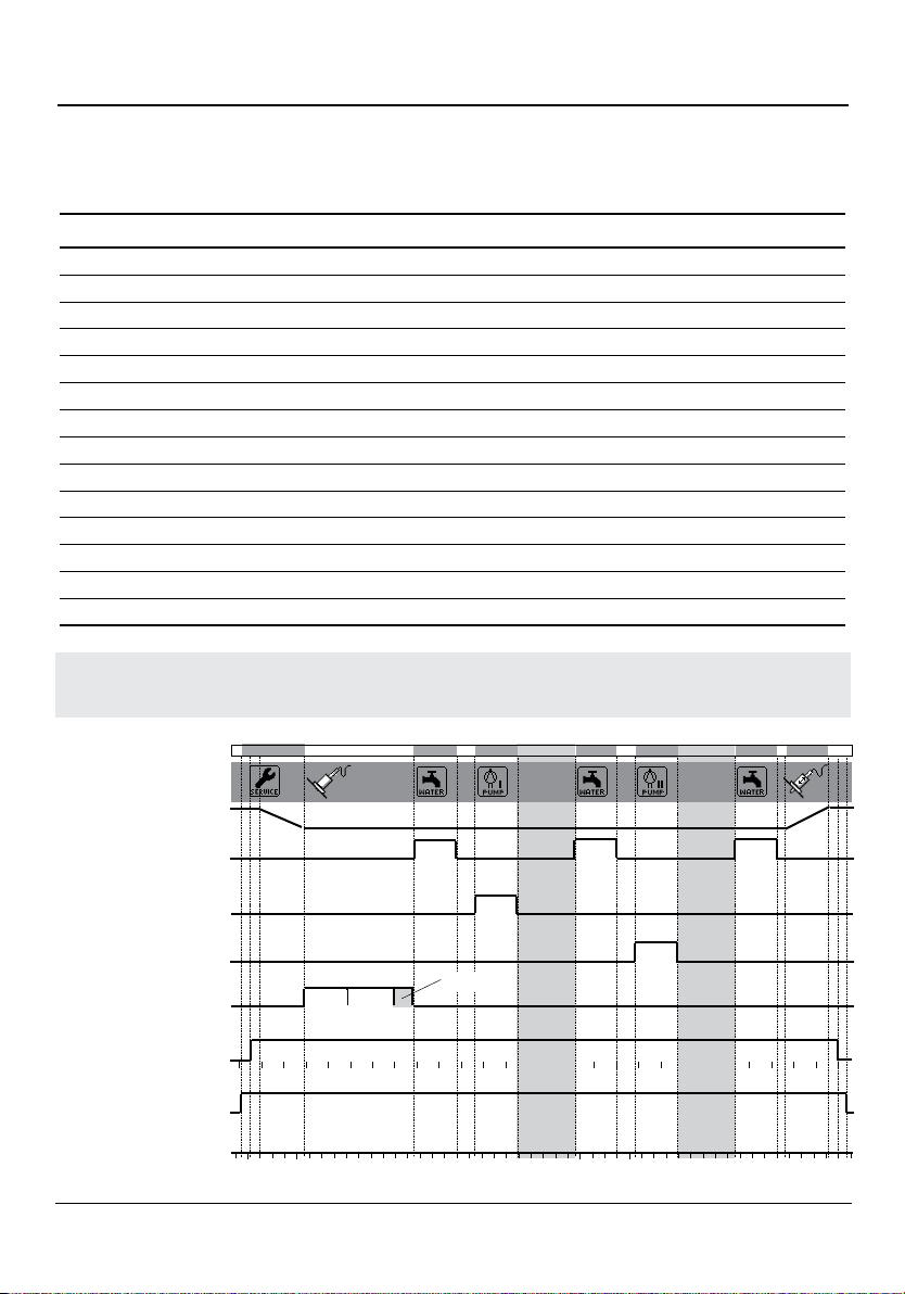
Calibration program
Parameter Setting: Program Flows
Cal 2point (Continuous), Media Monitoring Off
Display text Time [s]
01: Probe in SERVICE
02: Cleaning agent 0020 s
03: Rinse water ON 0060 s
04: Rinse water OFF 0002 s
05: Buffer I 0000 s
06: Cal Buffer 1
07: Rinse water ON 0010 s
08: Rinse water OFF 0002 s
09: Buffer II 0000 s
10: Cal Buffer 2
11: Rinse water ON 0010 s
12: Rinse water OFF 0002 s
13: Probe in MEASURE 0005 s
14: Program end
Cal 2point (continuous) can also be started via a DCS input signal at input BIN2
of the Unical 9000 probe controller.
Program step
Message (display)
Probe: Measure
Probe: Service
Rinse water
Buffer 4.01
(Pump I)
Buffer 7.00
(Pump II)
Cleaning agent
(Pump III)
HOLD
DCS ML3
(Program running)
01 02
Stroke 1
Stroke 2
03 04 05 06 07
Exposure time
Calibration
with 1st buffer
08 09 10
Calibration
with 2nd buffer
11 12 13 14
[t]
s
71
Page 72
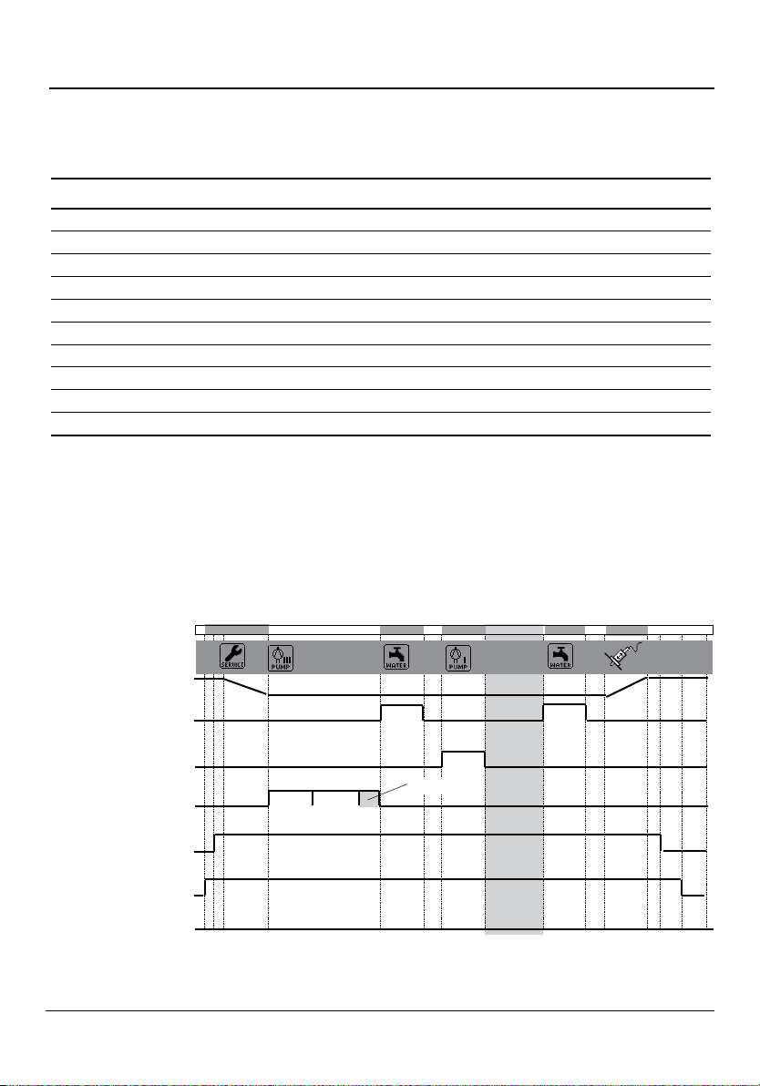
Parameter Setting: Program Flows
Cal 1point (Continuous), Media Monitoring Off
Display text Time [s]
01: Probe in SERVICE
02: Cleaning agent 0003 s
03: Rinse water 0010 s
04: Rinse water 0002 s
05: Buffer I 0000 s
06: Cal buffer 1 (pH 4.01)
07: Rinse water 0010 s
08: Rinse water 0002 s
09: Probe in MEASURE
10: Program end
Program step
Message (display)
Probe: Measure
Probe: Service
Rinse water
Buffer 4.01
(Pump I)
Cleaning agent
(Pump III)
HOLD
DCS ML3
(Program running)
72
01 02
Stroke 1
Stroke 2
03 04 05 06 07
Exposure time
Calibration with
1st buffer
08 09 10
[t]
s
Page 73
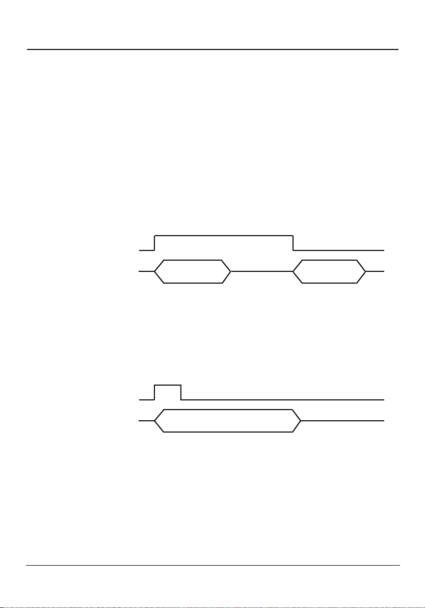
Park program
Park Program: Wait Position
The park program includes the programming step “Wait position”.
When the program is started via the DCS inputs BIN 1 ... BIN 3 on the
Unical 9000, the program will be executed until the “Wait position” is reached.
There it remains until the signal status at the DCS inputs changes.
• The program is started via the DCS inputs and remains in “Wait position”
until the assignment of the DCS inputs changes:
DCS inputs BIN 1 ... BIN 3
of Unical 9000
Program until
wait position
Program after
wait position
• The program is started by a short signal at the DCS inputs:
Wait position is skipped.
DCS inputs BIN 1 ... BIN 3
of Unical 9000
Program is executed completely.
Wait position is skipped.
Notice:
If the programs are started by the Protos 3400(X) from the Calibration or
Maintenance menu, the wait position will be skipped.
73
Page 74
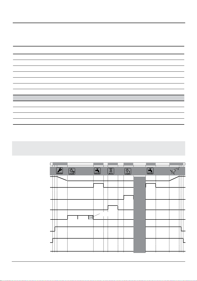
Parameter Setting: Program Flows
Parking
Display text Time [s]
01: Probe in SERVICE
02: Cleaning agent 0020 s
03: Rinse water ON 0060 s
04: Rinse water OFF 0002 s
05: Purge air ON 0010 s
06: Purge air OFF 0002 s
07: Cal buffer 1 (pH 4.01)
08: Wait position > Position will be held until next command (e.g., DCS)
09: Rinse water ON 0010 s
10: Rinse water OFF 0002 s
11: Probe in MEASURE 0005 s
12: Program end
Parking is started via a DCS input signal at input BIN3
of the Unical 9000 probe controller.
Program step
01 02
03 04 05 06 07
08 09 10
11
Message (display)
Probe: Measure
Probe: Service
Rinse water
Buffer 4.01
(Pump I)
Purge air
(AUX1 valve)
Cleaning agent
(Pump III)
HOLD
DCS ML3
(Program running)
74
Stroke 1
Stroke 2
Exposure time
Wait
Wait position
[t]
s
Page 75
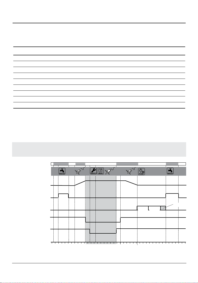
Parameter Setting: Program Flows
Measurement (Short-Time), Media Monitoring Off
Display text Time [s]
01: Rinse water ON 0010 s
02: Rinse water OFF 0002 s
03: Probe in MEASURE 0005 s
04: Meas duration 0030 s
05: Probe in SERVICE
06: Cleaning agent 0020 s
07: Rinse water ON 0060 s
08: Rinse water OFF 0002 s
09: Program end
Measurement (short-time) can also be started via a DCS input signal at input BIN1
of the Unical 9000 probe controller.
Program step
01 02
03 04 05 06
07 08
Message (display)
Probe: Measure
Probe: Service
Rinse water
Cleaning agent
(Pump III)
HOLD
DCS ML3
(Program running)
Probe in MEASURE
(short-time)
Stroke 1
Stroke 2
Exposure time
[t]
s
75
Page 76
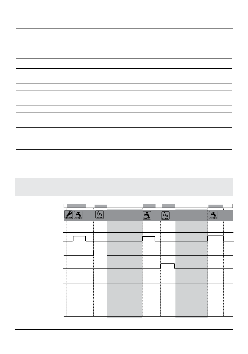
Parameter Setting: Program Flows
Cal 2point (Short-Time), Media Monitoring Off
Display text Time [s]
01: Rinse water ON 0010 s
02: Rinse water OFF 0002 s
03: Buffer I 0000 s
04: Cal Buffer 1
05: Rinse water ON 0010 s
06: Rinse water OFF 0002 s
07: Buffer II 0000 s
08: Cal Buffer 2
09: Rinse water ON 0010 s
10: Rinse water OFF 0002 s
11: Program end
Cal 2point (short-time) can also be started via a DCS input signal at input BIN2
of the Unical 9000 probe controller.
Program step
01 02
03 04 05 06
07
08 09
10
Message (display)
Probe: Measure
Probe: Service
Rinse water
Buffer 4.01
(Pump I)
Buffer 7.00
(Pump II)
HOLD
76
Calibration with
1st buffer
Calibration with
2nd buffer
[t]
s
Page 77
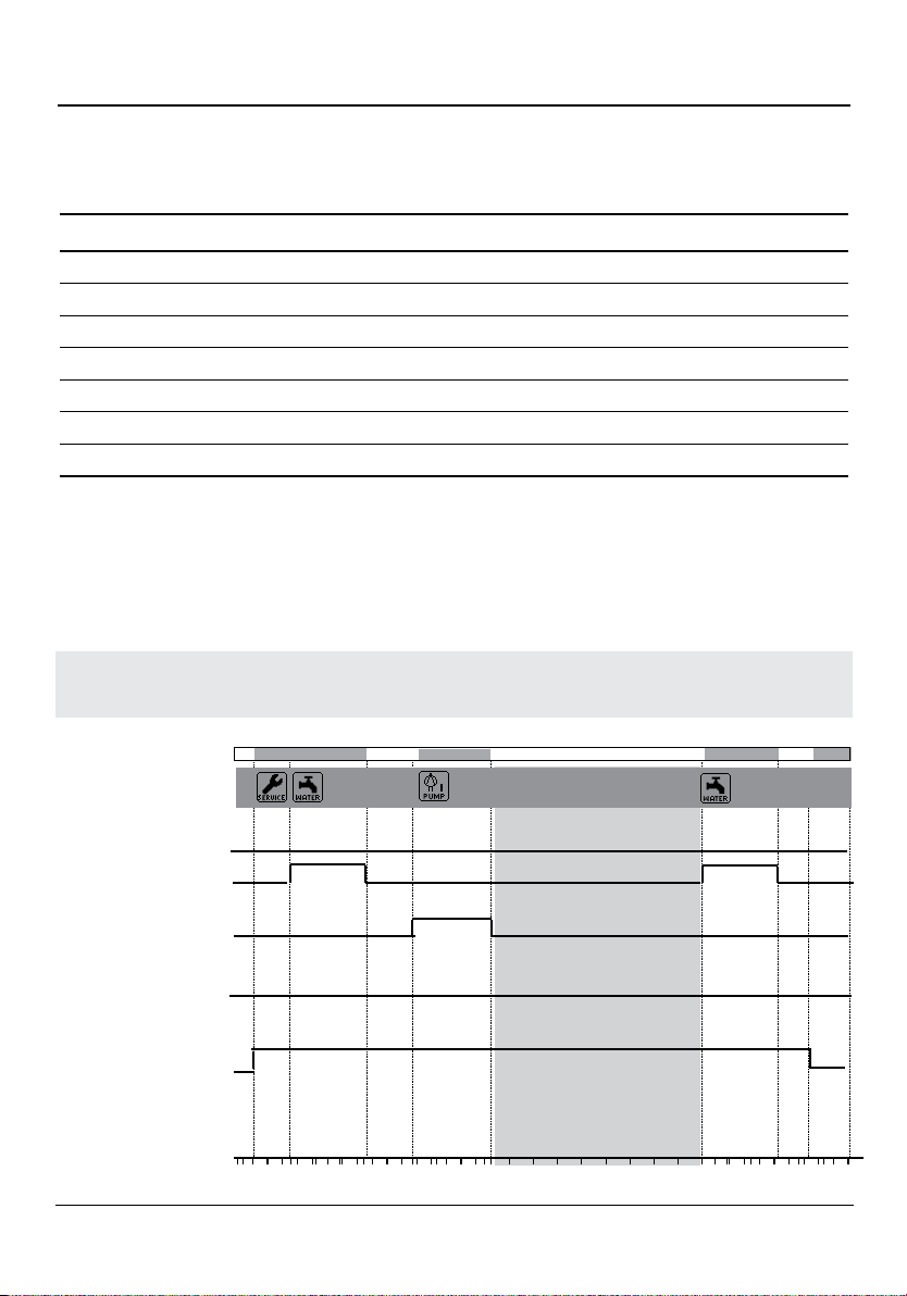
Parameter Setting: Program Flows
Cal 1point (Short-Time), Media Monitoring Off
Display text Time [s]
01: Rinse water ON 0010 s
02: Rinse water OFF 0002 s
03: Buffer I 0000 s
04: Cal buffer 1 (pH 4.01)
05: Rinse water ON 0010 s
06: Rinse water OFF 0002 s
07: Program end
Cal 1point (short-time)
Program step
Message (display)
Probe: Measure
Probe: Service
Rinse water
Buffer 4.01
(Pump I)
HOLD
DCS ML3
(Program running)
01 02
03 04 05 06
Calibration with
1st buffer
[t]
s
77
Page 78
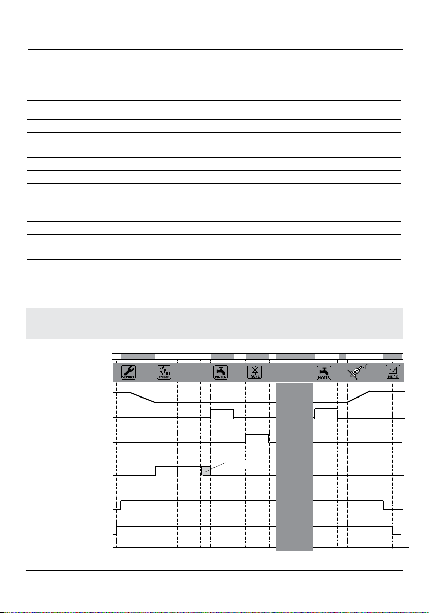
Service program
Parameter Setting: Program Flows
Service
Display text Time [s]
01: Probe in SERVICE
02: Cleaning agent 0020 s | Measure -> Service
03: Rinse water ON 0060 s |
04: Rinse water OFF 0002 s |
05: Purge air ON 0005 s |
06: Purge air OFF 0002 s |
07: Wait position | Service position
08: Rinse water ON 0010 s |
09: Rinse water OFF 0002 s |
10: Probe in MEASURE 0005 s | Service -> Measuring
11: Program end
Service can also be is started via a DCS input signal at input M/S
of the Unical 9000 probe controller.
Program step
Message (display)
Probe: Measure
Probe: Service
Rinse water
Purge air
(AUX1 valve)
Cleaning agent
(Pump III)
HOLD
DCS ML3
(Program running)
01 02
Stroke 2
Stroke 1
Part 1: Measure —> SERVICE
03 04
Exposure time
05
78
06
07
08 09 10 11
Wait position
Part 2: SERVICE —> Measure
Page 79
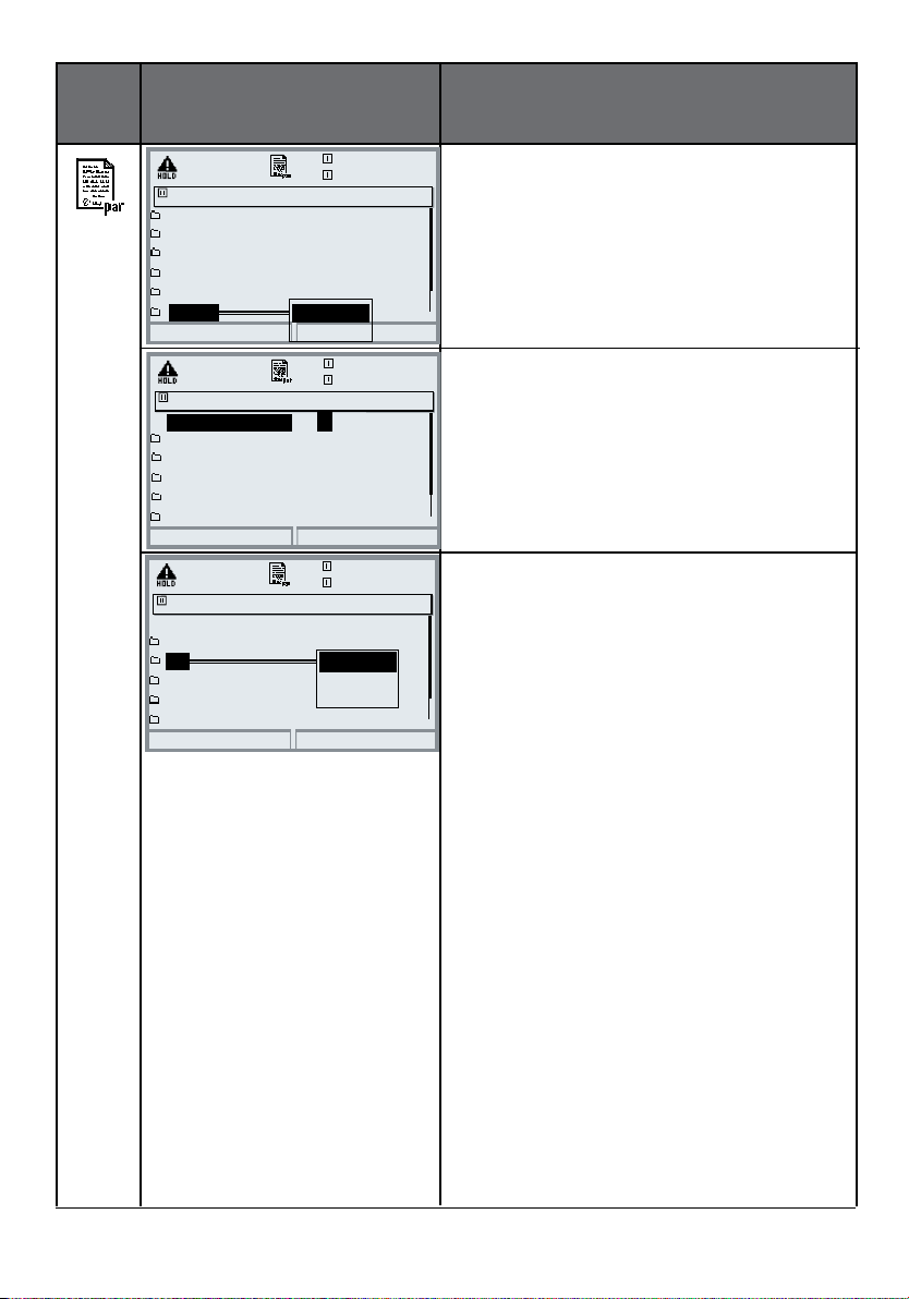
Menu Display
Parameter setting
Program flow
Program flow (Administrator)
Clean
Cal 2point
Cal 1point
Service
Parking
User 2
Abort
User 2 (Administrator)
Program name
01: Probe in SERVICE
02: Cleaning agent
03: Rinse water ON
04: Rinse water OFF
05: Buffer I
Abort
Example (Administrator)
Program name
01: Probe in SERVICE
02:
03: Rinse water ON
04: Rinse water OFF
05: Cleaning agent
Abort
approx. 2:02 min
approx. 2:50 min
approx. 2:26 min
approx. 2:40 min
Edit:
Copy
U
0020 s
0060 s
0002 s
0000 s
Example
Edit:
Insert
Delete
0020 s
7.05 pH
25.6 °C
7.05 pH
25.6 °C
ser-2-----------
OK
7.05 pH
25.6 °C
OK
Configuring the Program Flow
Parameter setting / Probe control /
Program flow / User 2:
Select “Edit” using arrow keys,
confirm with enter
Entering a Program Name
A new program name can be entered
using the arrow keys.
Confirm the name with enter
Editing a Program Step
Select the program step you want to
edit using the arrow keys.
Press enter:
Now you can choose between
“Edit, Insert, Delete”.
• Edit:
Allows selecting a function
• Insert:
Inserts an empty step above the
selected program step and then
allows selecting a function by
“editing” the empty step.
Allows selecting a function
• Delete:
The program step is deleted.
79
Page 80
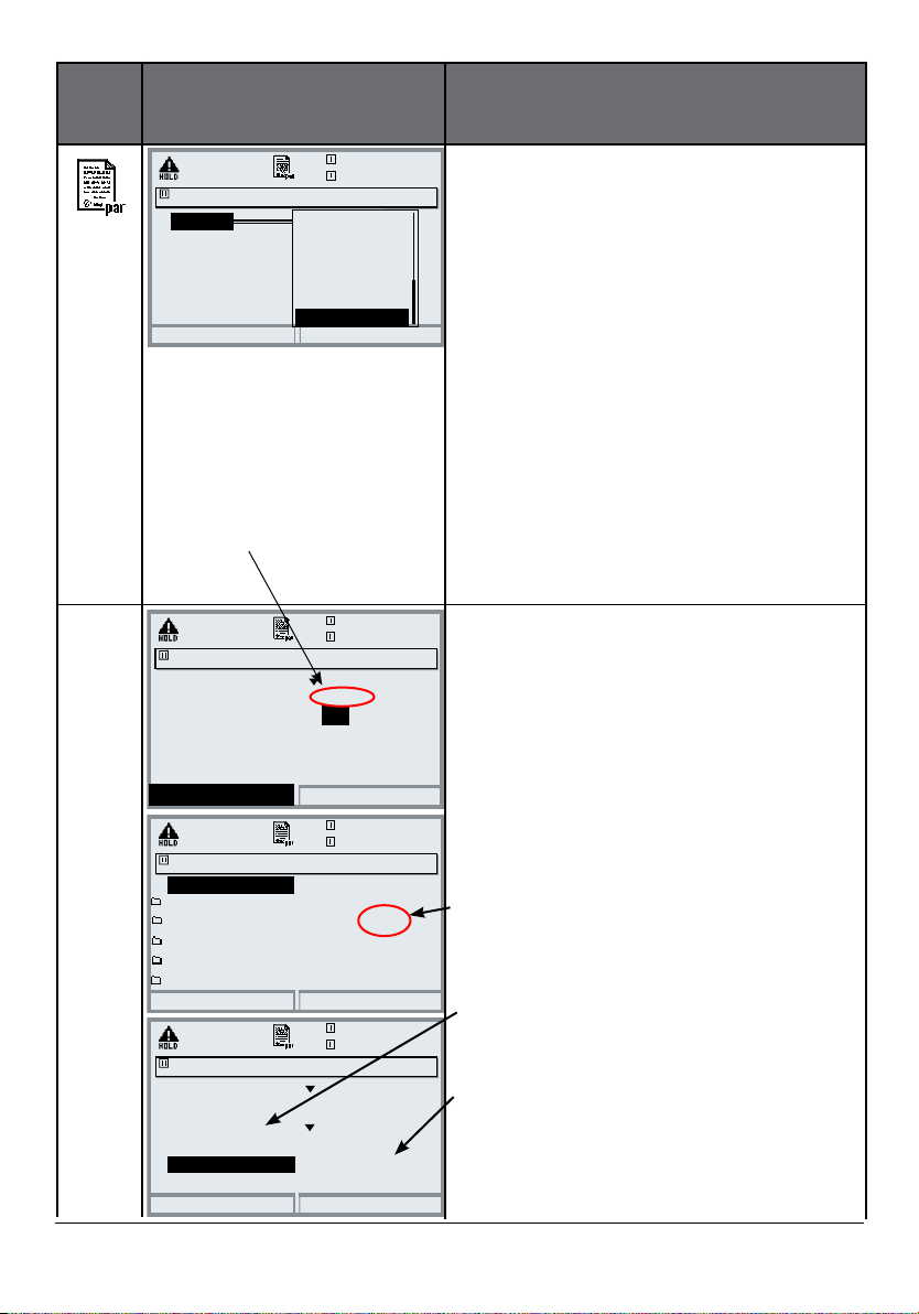
Menu Display
• Configure function
• Activate monitoring
7.05 pH
Program flow (Administrator)
Function
Abort
For valve functions the run time
must be specified, for pumps
the exposure time.
Example (Administrator)
Function
Run-time
Monitoring
Return
Example (Administrator)
Program name
01: Probe in SERVICE
02: Cleaning agent 0020 s Chk
03: Rinse water ON
04: Rinse water OFF
05: Pump
Return
Media adapter (Administrator)
Port III
Medium
Monitoring
Setpoint
Adm. deviation
25.6 °C
Cal Buffer 1
Cal Buffer 2
Purge air On
Purge air Off
Aux medium On
Aux medium Off
Blank step
OK
7.05 pH
25.6 °C
Cleaner On
0020 s
Off
On
7.05 pH
25.6 °C
Example 1
0060 s
0002 s
0000 s
7.05 pH
25.6 °C
Cleaning valve
Mr Proper
Process value
09.20 pH
01.00 pH
Configuring a Function
Select a function using arrow keys,
confirm with enter
Program end
Probe in SERVICE
Probe in MEASURE
Rinse water On
Rinse water Off
Wait time
Buffer I - - - Text can be edited during installation
Buffer II - - Text can be edited
Cleaning agent - Text can be edited
Cal Buffer 1
Cal Buffer 2
Purge air On - Text can be edited
Purge air Off - Text can be edited
Aux medium On - Text can be edited
Aux medium Off - Text can be edited
Wait position
Goto line
ORP check
Activating Monitoring
(see “Media monitoring”)
With several functions you can
monitor the media used in the
calibration chamber (“Monitoring:
On”) (e.g. cleaning agent, buffers,
rinse water, ...).
The respective program step is then
marked with “Chk”.
In any case it is necessary that you
select the monitoring function for the
respective medium in the “Installation”
menu and specify valid tolerance
limits for temperature or process
value, otherwise the respective line is
not displayed.
80
Return
Page 81
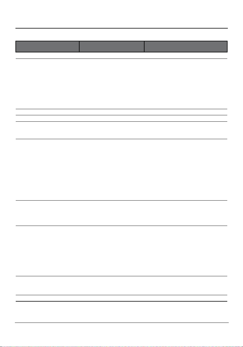
Parameter setting: Installation
Parameter Setting: Installation
Configuration of Unical 9000 Functions
Installation Default setting Adjustable parameters
• Measurement procedures Continuous (Short-time)
• Ext. control (DCS) (Polarity / Output settings)
- Signal level of inputs
DCS (36 ... 39)
M/S (42, 43)
A/M (40, 41)
- DCS output (34) Measure Alarm
- Signal level of outputs
DCS (31 ... 34)
• Sensor detection Off On
• Immersion lock Off Sensocheck Glass el
• Access manual control Access code for manual
• Probe
- Probe type Ceramat (SensoGate, InTrac, Other)
- Max. move time 0015 s
- Safety valve No (Yes)
- Sealing water Off (On)
- Cavity rinsing Off (Off, Interval, Continuous:
- Check interval Off On (Check after travels)
- Maintenance interval Off On (Maintenance after travels)
• Rinse water
- Monitoring Off (Process value/Temperature)
- Setpoint +07.00 pH
- Adm. deviation 01.00 pH
• Media adapter
- Port I ... III Off* “Pump” or “Off”
- Medium: --- (e.g. “Buffer I”)
- Displaced volume 25 ml (50 / 75 / 100 ml)
- Residual volume 250 ml (0 / 250 / 500 ml)
- Monitoring Off (Process value/Temperature)
- Setpoint 07.00 pH (Process medium or temp)
- Adm. deviation 0.50 pH
• Additional media
- Additional medium 1 Off (On - with monitoring)
- Additional medium 2 Off (On - with monitoring)
• Start-up No Yes/No
• System forecast Off Off / On: Monitors the probe travels for
Active: 10 ... 30 V (Active: 10 ... 30 V / active < 2V)
N/O (N/O / N/C)
control (Maintenance menu)
Default: 2598
Default for interval: 0001.0 h,
Rinse duration: 05 s)
predictive maintenance of Ceramat und
SensoGate
*Automatic adjustment by “Plug & Play” in: System control / Factory setting Probe control
81
Page 82
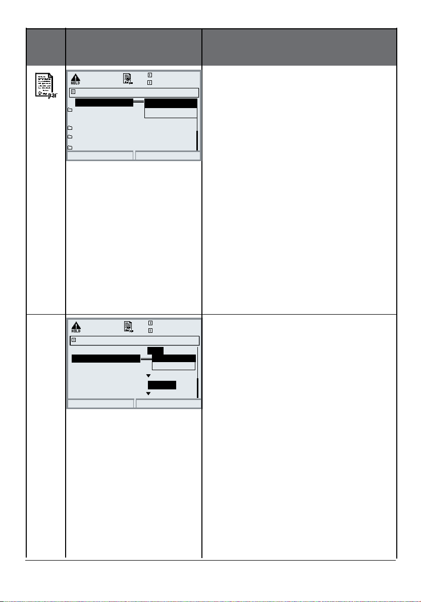
Menu Display
• Meas. procedure
• External control via DCS
Installation (Administrator)
Meas. procedure
Ext. control (DCS)
Sensor detection
Access manual control
Probe
Rinse water
Return
Ext. Control (DCS) (Administrator)
Control
DCS inputs (36...39)
M/S input (42/43)
A/M input (40/41)
DCS output (34)
DCS outputs (31…34)
Return
Continuous
Short-time
On
active 10...30V
active < 2 V
active 10...30 V
Measure
N/O
7.05 pH
25.6 °C
7.05 pH
25.6 °C
Off
Alarm
Selecting the Measurement Procedure
• Continuous measurement:
With continuous measurement
the pH electrode is located in the
process medium and is retracted for
calibration or cleaning.
• Short-time measurement:
(interval measurement, sampling,
sample mode ...)
The pH electrode is only momentarily moved into the process
medium. This method is applied
when measuring aggressive or thermally demanding process media
which require short measurement
times with long rest periods.
External Control via DCS
• DCS inputs: Inputs for selecting the
control programs. Here, the active
signal level is specified.
( < 2 V or 10 ... 30 V).
• M/S input: Control of probe
movement
• A/M input: Intervals automatic /
blocked
• DCS output (34): Specify output signal for terminal 34:
- Measuring or
- Alarm
• DCS outputs (31 … 34):
Specify contact type (N/O, N/C)
82
Page 83
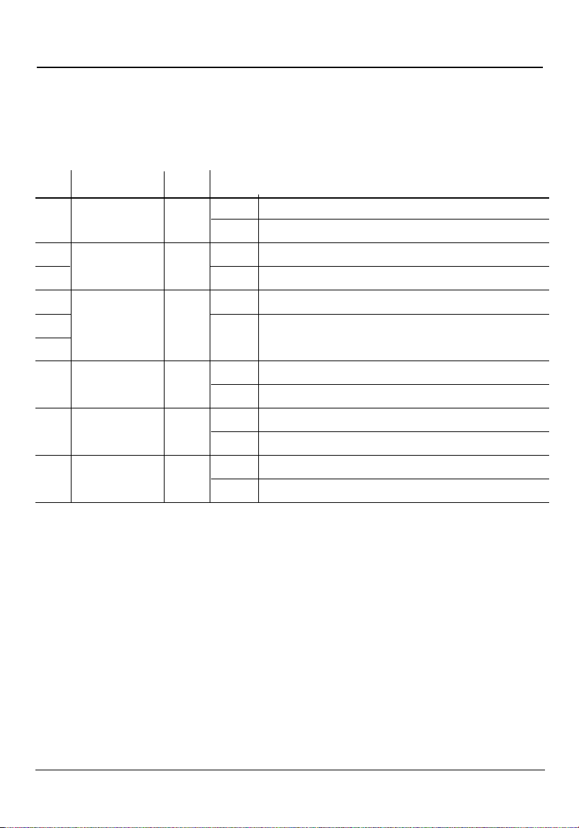
Control via process control
system
Control via Process Control Cystem (DCS)
Inputs/Outputs of Unical 9000(X)
42
40
37
38
39
Designation I / O FunctionNo.
Measuring/
Service
Auto / Manual
Bin 3
Bin 2
Bin 1
Measuring***
(user-defined:
“Alarm”)
Service
Program runs
Level
Probe moves to measure position
I
I
0
Probe moves to service position43
1
Automat. interval control from Unical
0
Automat. intervals locked41
1
I Program selection and start, manual / DCS
(Program 1 ... 6 - see next page)
O34
O33
O32
0
Probe in “MEASURE” position
1
0
Probe in “SERVICE” position
1
0
Program running
1
* Passive contacts,
24 V must be supplied externally or via DCS
*
*
* **
*
*
*
** Signal duration at least 2 s (passing contacts)
*** As delivered, the signal output DCS 34 serves for probe position
feedback – as shown. However, you can also program this output as
“Alarm”. Then it sends a signal to the DCS in the event of calibration
errors or faulty probe movement.
83
Page 84
Control Programs and Meas. Procedures
Factory Settings
Control Programs of Unical 9000(X)
6 programs and one service program can be started. 5 program flows are
preset. 2 further programs can be entered by the user (User 1, User 2).
The programs are started ...
• for manual operation via Protos 3400(X)
• remotely via DCS or switch with passive inputs Bin 1 ... 3
(24 V must be externally supplied, see Specifications)
Program Description Bin 3 Bin 2 Bin 1
1 Cleaning 0 0 1
2 Two-point calibration (Cal 2point) 0 1 0
3 One-point calibration (Cal 1point) 0 1 1
4 Park position 1 0 0
5 User-programmable (User 1) 1 0 1
6 User-programmable (User 2) 1 1 0
7 Service program Request via M/S
The service program (7) stops all other running programs (1 - 6) immediately
and erases stored requests. For programs 1-6 the following applies:
When you start a new program, the remaining steps of a currently running
program are executed first. Further requests are stored and executed subsequently. When you control the Unical 9000(X) via Protos 3400(X), you can block
the Bin 1, Bin 2, Bin 3 signal lines as well as M/S and A/M to prevent conflicts
(Parameter setting / Probe control / Installation / Ext. control (DCS): Off)
Measurement Procedures
• Continuous measurement: After cleaning / calibration the probe moves into
the process for measurement
• Short-time measurement (interval measurement, sampling, sample mode
...): After cleaning / calibration the probe remains in the calibration chamber
and only moves into the process for measurement upon request.
84
Page 85
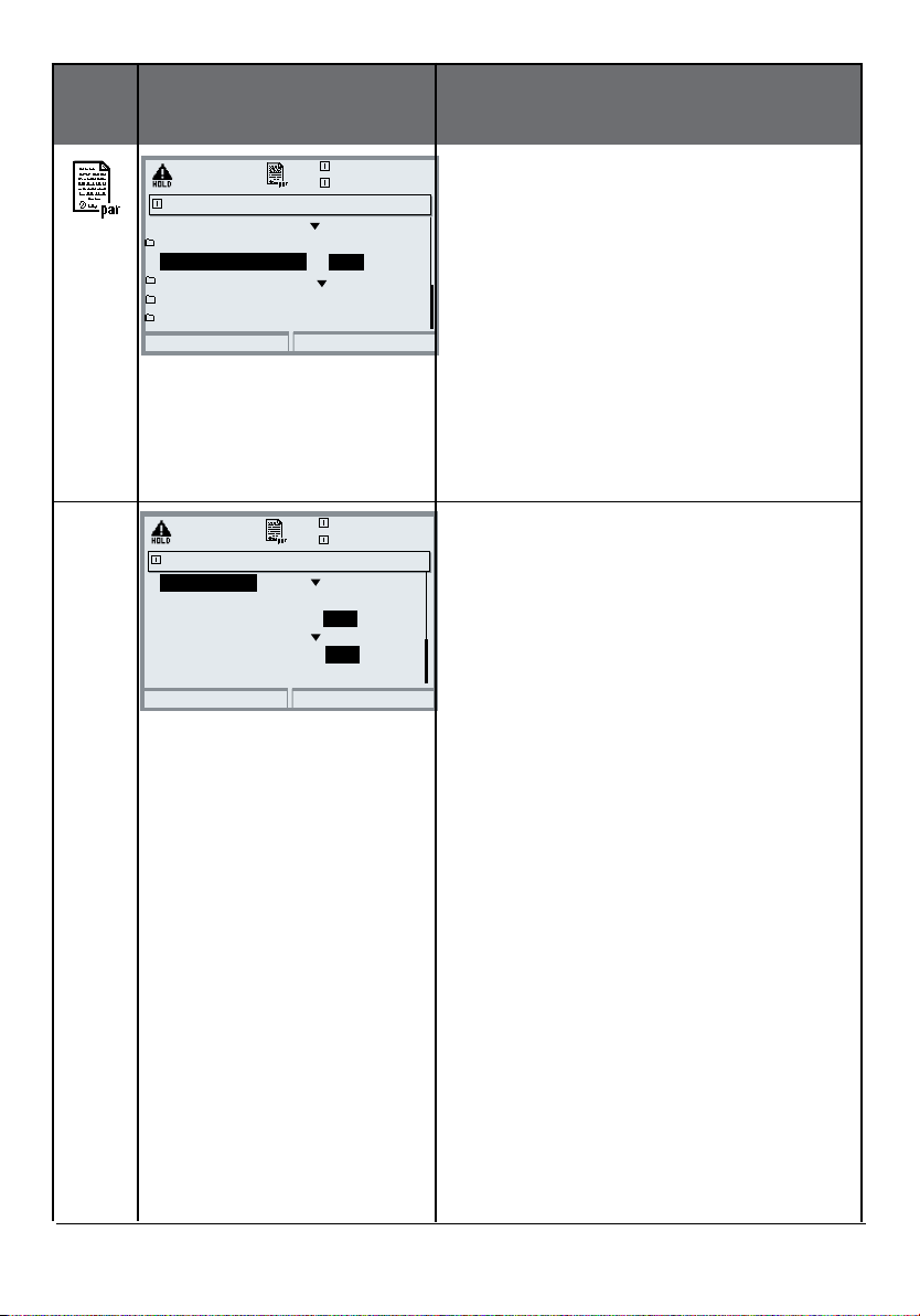
Menu Display
• Sensor detection
• Probe
Installation (Administrator)
Meas. procedure
Ext. control (DCS)
Sensor detection
Immersion lock
Access manual control
Probe
Return
Probe (Administrator)
Probe type
Move time max.
Sealing water
Cavity rinsing
Check interval
Check after travels
Return
7.05 pH
25.6 °C
Continuous
On
Off
Off
7.05 pH
25.6 °C
Ceramat
006 s
On
Off
Off
On
Off
20000
Sensor Detection
Sensor detection “On” prevents
accidental probe movement when the
electrode has been removed.
This is done by checking whether the
temperature detector integrated in
the sensor is connected.
Probe
Selecting the retractable fitting.
Here, the max. move time is automatically adjusted (depending on model).
Sealing Water
Sealing water is switched on shortly
before the probe movement is started
to keep the rinsing chamber free from
medium. This is important for processes containing fibrous or adhering
media.
The sealing water pressure must be
higher than the medium pressure.
Intrusion of medium is prevented by
the counter-pressure in the rinsing
chamber which is caused by the
sealing water.
Check Interval, Maintenance Interval
Permits specifying the max. admissible
number of move cycles until a message
is generated, factory setting:
Check after travels: 20000
Maintenance after travels: 100000
85
Page 86
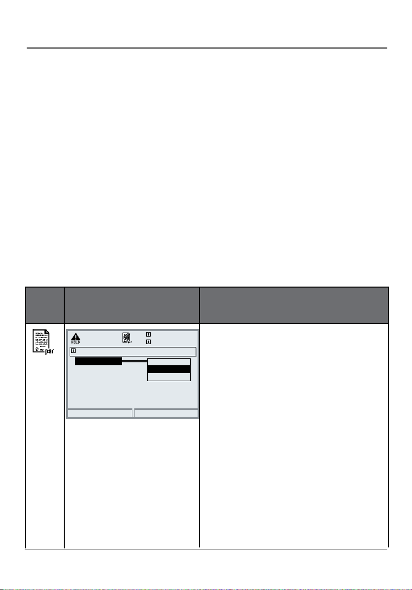
Configuring media monitoring
Configuring Media Monitoring
Parameter setting / Unical 9000 / Installation
Media Monitoring
For perfect system control, the pH value (or temperature) of the media used
(buffer solutions, cleaning solution, rinsing water ...) can be checked against a
specified value in the calibration chamber. This ensures that only correct media
are used in the calibration chamber of the probe. Exchanged or contaminated
media or media with a wrong temperature are recognized.
In that case a message will be released. If faulty media are recognized before a
calibration step, that step will not be performed.
NOTICE!
When monitoring the pH value of a medium, the zero and slope deviations
of the electrode must be taken into account. Therefore the value specified for
“adm. deviation” must not be too low!
Menu Display
Rinse water (Administrator)
Monitoring
Setpoint
Adm. deviation
86
Return
7.05 pH
25.6 °C
Off
Process value
Temperature
Configuring the
media monitoring
Media monitoring can be configured
in the “Parameter setting / Probe
control / Installation” menu for:
• Rinse water
• Media at media adapter
(... in the “Media adapter” menu)
• Additional media
The process value or temperature
of the media can be monitored.
Please note that the value specified
for “Adm. deviation” should not be
too low. The minimum response
time is automatically taken into
account when configuring the user
programs.
Page 87
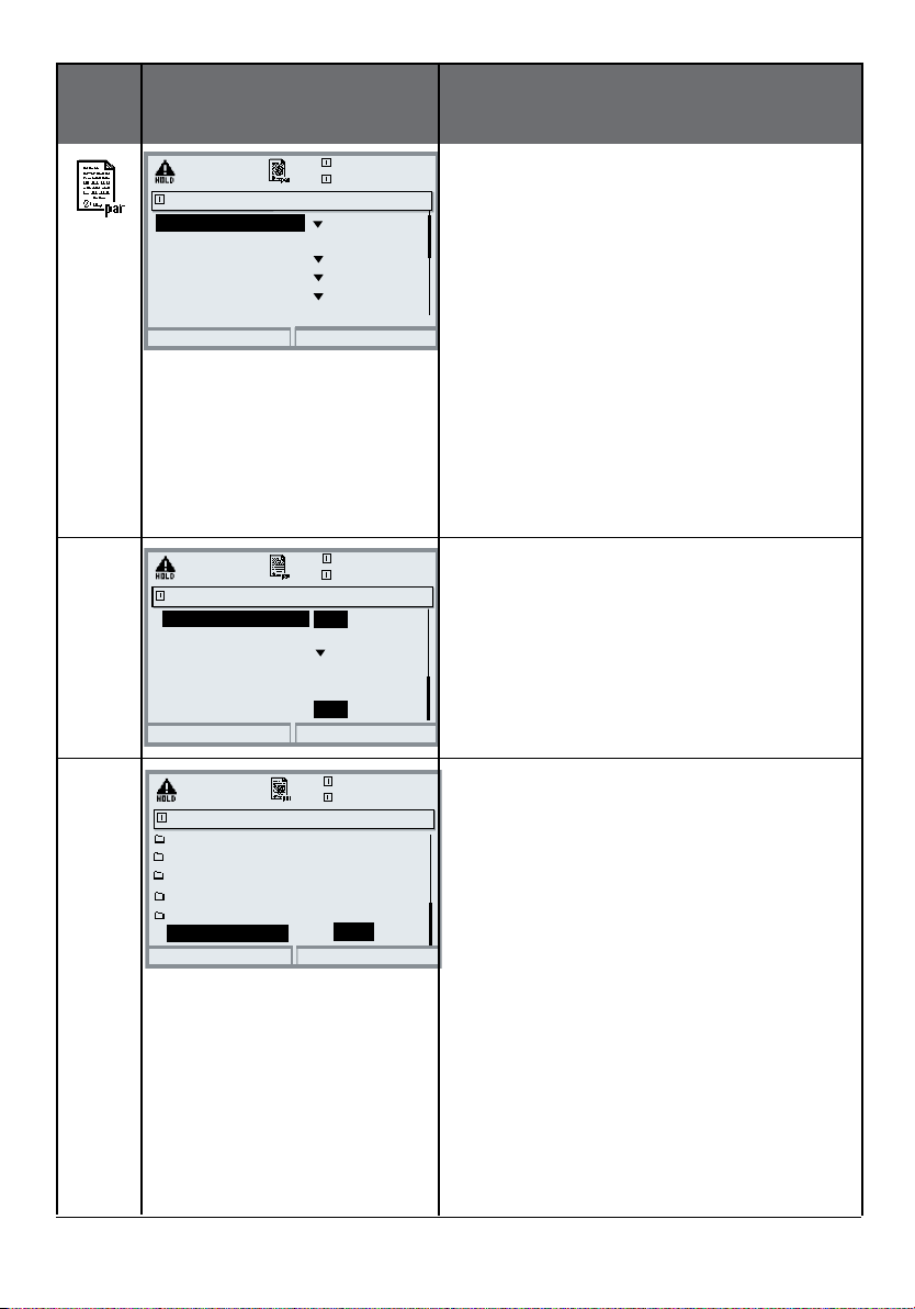
Menu Display
• Media adapter, Additional media
• Start-up
Media adapter (Administrator)
Port I
Medium
Displacement volume
Residual volume
Monitoring
Setpoint
Return
Additional media (Administrator)
Additional medium 1
Medium
Monitoring
Setpoint
Adm. deviation
Additional medium 2
Return
Installation (Administrator)
Access manual control
Probe
Rinse water
Media adapter
Additional media
Start-up
Return
Metering pump
Buffer - I -------
25 ml
250 ml
Process value
+07.00 pH
On
Purge air-----
Process value
+07.00 pH
00.20 pH
On
No
Yes
7.05 pH
25.6 °C
7.05 pH
25.6 °C
Off
Off
7.05 pH
25.6 °C
Media Adapter
• Specifying the equipment
(Metering pump, Off, or Cleaner)
• Designation of medium
• Specifying the displaced volume
depending on model, e.g.:
Ceramat 25 ml
InTrac 77Xe 50 ml
InTrac 797e 75 ml
InTrac 798e 100 ml)
• Residual volume
• Monitoring (Process value/Temp)
• Setpoint
Additional Media (2)
• Specifying the equipment
(On, Off)
• Designation of medium,
• Monitoring (Process value/Temp)
• Setpoint
Start-Up
At the end of the parameter-setting
procedure, a “Start-up” line appears in
the “Installation” menu. When you are
sure to have set all parameters, select
“Yes” to confirm. Now the pumps
perform the number of stroke movements required for filling the media
tubes completely.
The necessary rinsing cycles are
automatically started.
87
Page 88
System forecast
System Forecast (Ceramat, SensoGate)
Monitoring the probe travel behavior of retractable fittings
(with Unical 9000(X) software version 4.3 or higher)
The "System Forecast" function
enables monitoring of the probe
travel behavior of the Ceramat or
SensoGate retractable fittings.
Possible signs of wear are detected in
good time to prevent failure or downtimes ("predictive maintenance").
Fittings frequently display signs
of wear as a change in their travel
behavior. The travel time can increase
significantly, for example, if aggressive media or critical processes cause
monitored probe
travel
SensoGate in Service
position...
... and in
Process position
the retractable fitting to become
sticky or seals to swell. The switching
behavior of control elements such
as piezo valves also changes in the
course of time, particularly with long
dwell times in one position.
The opening and closing times as well as the passing capacity of these valves
can then be significantly changed. Over time, pneumatically-controlled valves
are also subject to changed switching times as a result of increasing friction,
fatty deposits or other influences. The "System Forecast" determines whether
the probe movement is continuous or jerky, which, for example, would indicate
resinified fat. These changes can be recorded in a probe travel profile.
By comparing with reference times, an expert
can draw conclusions on the status of the separate components, and the system itself can
Message list
U172
Warn SP probe sluggish
UNICAL
active
1 messg.
generate appropriate messages, see example
(menu "Diagnostics / Message list").
Return
88
Page 89
System Forecast: Probe Travel Profiles
Reference / Probe Travel Profiles
Following installation of a system or after a repair, several cycles are run by calling the "System forecast / Edit reference profile" function. The travel behavior
(probe travel profile) detected is saved as a "reference profile" with time and
date. A distinction is made here between retraction behavior S (service) and
insertion behavior P (process).
Creation of a Probe Travel Profile and Presentation in Protos
Menu: Parameter setting / Probe control / Installation / System forecast
07.00 pH
System forecast (Administrator)
Active reference profile
12/21/16 12:37 S a06 b17 c25 d33 e02 CM
12/21/16 12:37 P a09 b16 c26 d34 e02 CM
Auto - New record
Edit reference profile
Tolerances
Return
25.6 °C
Auto
Yes
The active reference profile contains the
following parameters:
No
12/21/16 12:37 S a06 b17 c25 d33 e02 CM
CM/SG probe type
CM: Ceramat, SG: SensoGate
aXX … eXX Records of separate travel times
aXX: Time [1/10 s] from run command to response of air sensor.
bXX: Time [1/10 s] from run command until drop-out of the exit limit position.
cXX: Time [1/10 s] from run command to response of desired limit position.
dXX: Time [1/10 s] from run command to drop-out of air sensor.
eXX: Counter: number of air current interruptions during a travel cycle.
S/P: Direction of travel
S: Service position
P: Process position
Date and time of profile creation
89
Page 90
Setting the system forecast parameters
Setting the System Forecast Parameters
Menu: Parameter setting / Probe control / Installation / System forecast
Menu Display System forecast
07.00 pH
Yes
25.6 °C
No
7.00 pH
25.6 °C
WA150
System control (Administrator)
Probe
Rinse water
Media adapter
Additional media
System forecast
Start-up
Return
Note:
Clicking on "System forecast"
brings up the following message:
“Please wait! Function is executed".
Protos initially reads the data for
the reference profile saved in the
Unical. This can take some time.
System forecast (Administrator)
Active reference profile
12/21/16 12:37 S a06 b17 c25 d33 e02 CM
12/21/16 12:37 P a09 b16 c26 d34 e02 CM
Edit reference profile
Tolerances
Messages
Return
Setting the system forecast
parameters
(only Ceramat and SensoGate types)
Select a Ceramat or SensoGate
retractable fitting from within the
"Probe" menu item. Further parameters can then be set under "System
forecast".
Active reference profile
Reference profiles are preinstalled by
default for the following probes:
Ceramat WA150
Ceramat WA160
SensoGate WA130S (short)
SensoGate WA130L (long)
These profiles can be selected under
"Active reference profile".
They are based on the following
process conditions:
Process pressure: 3 bar
Compressed air: 5 bar
Unical hose length: 5 m
Temperature: 20 °C
90
In the event of greater deviations in
the process conditions, you should
create an individual “User” reference
profile.
Page 91
System Forecast: Reference Profile
Menu: Parameter setting / Probe control / Installation / System forecast
Menu Display
System forecast
Active reference profile
12/21/16 12:37 S a06 b17 c2
12/21/16 12:37 P a09 b16 c2
Auto - New record
Edit reference profile
Tolerances
Return
System forecast
Active reference profile
12/21/16 12:37 S a06 b17 c25 d33 e02 CM
12/21/16 12:37 P a09 b16 c26 d34 e02 CM
Auto - New record
Edit reference profile
Tolerances
Return
System forecast
01/01/00 00:00 S a00 b00 c00 d00 e00 X Auto
01/01/00 00:00 P a00 b00 c00 d00 e00 X Auto
............................................................................................
12/21/16 12:37 S a06 b17 c25 d33 e02
12/21/16 12:37 P a09 b16 c26 d34 e02
7.00 pH
25.6 °C
Auto
User
WA 150
WA 153
WA 154
WA 160
OK
7.00 pH
25.6 °C
Auto
Yes
7.00 pH
25.6 °C
System forecast:
Active reference profile
Active reference profile “Auto”
A reference profile is recorded
in the background during the
first probe movements (at least
20probe movements).
Auto - New record
The old reference profile is deleted
and and a new one is recorded.
No
While recording is in progress,
all values are set to “0” and the “Auto”
remark is active.
Return
7.00 pH
System forecast
12/21/16 12:37 S a06 b17 c25 d33 e02 CM Auto
12/21/16 12:37 P a09 b16 c26 d34 e02 CM Auto
............................................................................................
12/21/16 12:37 S a06 b17 c25 d33 e02
12/21/16 12:37 P a09 b16 c26 d34 e02
12/21/16 12:37 S a06 b17 c25 d33 e02
Return
25.6 °C
“Auto” reference profile created
After 20 probe movements the reference values are created. They are
followed by the probe identifier
(CM=Ceramat, SG=SensoGate) and
"Auto" for the reference profile.
91
Page 92
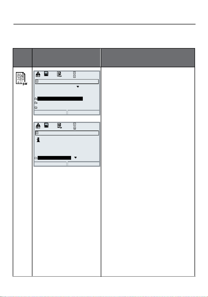
System forecast: create reference profile
System Forecast: Creating a Reference Profile
Menu: Parameter setting / Probe control / Installation / System forecast
Menu Display
System forecast
Active reference profile
12/21/16 12:37 S a06 b17 c25 d33 e02 CM
12/21/16 12:37 P a09 b16 c26 d34 e02 CM
Edit reference profile
Tolerances
Messages
Return
Edit reference profile (Administrator)
Record new profile with "Start"
softkey
12/21/16 12:37 S a06 b17 c25 d33 e02 CM
12/21/16 12:37 P a09 b16 c26 d34 e02 CM
Reference profile
Return
Start
7.00 pH
25.6 °C
User
7.00 pH
25.6 °C
User
System forecast:
Active reference profile: “User”
Creating a “User” reference profile
By selecting "Edit reference profile",
you can create an individual “User”
reference profile. Use the Start soft-
key to record a reference profile. For
this purpose, six probe movements
are executed. The reference profile is
the average of the recorded values.
Auto, User reference profiles:
Setting tolerances
For monitoring during operation,
permissible deviations in the separate travel times can be set in the
"Tolerances" menu. The tolerances
a...e are permissible deviations from
the active reference profile.
– See next page
The name "User" cannot be modified
by the user. The new profile is identifiable by the date and time of its
recording.
92
Page 93
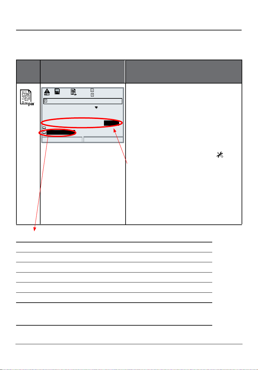
System forecast: Tolerance specifications
System Forecast: Tolerance Specifications
Menu: Parameter setting / Probe control / Installation / System forecast
Menu Display System forecast: Tolerances
7.00 pH
Off
25.6 °C
WA150
On
System control (Administrator)
Active reference profile
12/21/16 12:37 S a06 b17 c25 d33 e02 CM
12/21/16 12:37 P a09 b16 c26 d34 e02 CM
Monitoring
Edit reference profile
Tolerances
Return
Tolerance specifications
For monitoring during operation,
permissible deviations in the separate travel times can be set in the
"Tolerances" menu. The tolerances
"a...e" are permissible deviations
from the active reference profile.
If monitoring is set to "on", the
icon is displayed in measuring mode
if a tolerance limit is exceeded – the
corresponding message text can
be viewed under "Diagnostics /
Messages".
Tolerances (tol.) Input range
a Probe valve switching time (tol.+) 00 ... 99 [1/10 s]
b Exit of limit position (tol.+) 00 ... 99 [1/10 s]
c Achievement of limit position (tol.+) 00 ... 99 [1/10 s]
d Air sensor deactivated (tol.+) 00 ... 99 [1/10 s]
Air sensor deactivated (tol.–) 00 ... 99 [1/10 s]
e Air current interruptions (tol.+) 01 ... 09 [number]
Reference profile tolerance 00 ... 99 %
93
Page 94
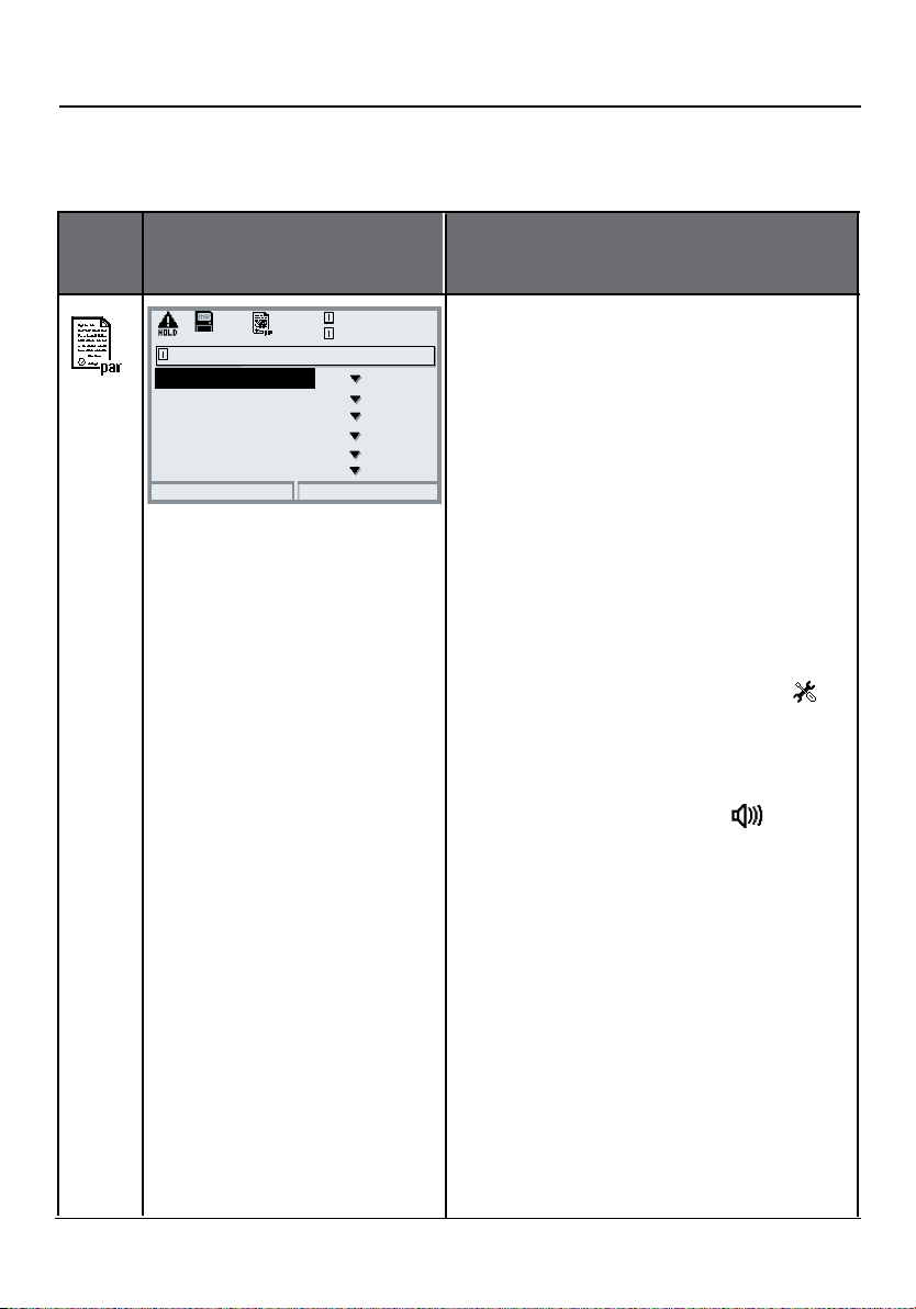
System Forecast: Reference Profiles, Messages
Menu: Parameter setting / Probe control / Installation / System forecast
Menu Display System forecast
Messages
Monitoring
U160 Pressure loss/Air sensor
U161 Probe valve not functioning
U162 Air sensor not functioning
U163 Probe valve sluggish
U164 Air sensor sluggish
Return
7.00 pH
25.6 °C
Maintenance
Active
Active
Active
Active
Active
Reference profiles, messages
Monitoring allows forecast messages
to be switched off (“Off”)
or to be output as
maintenance message (“Maintenance”)
or as failure message (“Failure”).
The corresponding message text
can be viewed under "Diagnostics /
Messages".
The individual messages can be set to
“active” or “inactive” (switched off ).
With “Maintenance” selected, the
icon is shown in measuring mode
when a tolerance is exceeded.
With “Failure” selected, the
icon
is shown in measuring mode when a
tolerance is exceeded.
94
Page 95
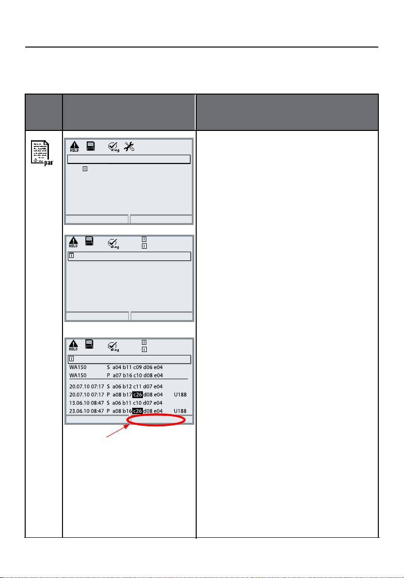
System Forecast: Diagnostic Messages
Menu: Diagnostics / System forecast
Menu Display System forecast: Diagnostics
UNICAL
active
S >>>
S >>>
1 messg.
7.00 pH
25.6 °C
7.00 pH
25.6 °C
Message list
U168
SP SERVICE position not functioning
Return
System forecast
12/21/16 12:37 S a06 b17 c25 d33 e02 CM
12/21/16 12:37 P a09 b16 c26 d34 e02 CM User
Load probe travel profile
Return
System forecast
Return
For better comparability, the travel
cycles can be displayed using the right
softkey:
- in Service “S“ and Process “P“
directions
- in Service "S" direction only
- in Process "P" direction only
Message list
When you have activated "Monitoring
On" in the System forecast menu, a
violation of a preset tolerance will
generate a message text. These texts
can be viewed in the message list.
System forecast
In operation, travel times are saved
for every cycle (max. 200) and are
compared with the active reference
profile.
If "System forecast" is selected in
the diagnostics menu, the active
reference profile and probe profiles
already recorded are displayed (this
may take some time). If tolerance limits are exceeded in the probe travel
profile, the error number is displayed
after the probe profile.
NOTICE
In the Protos/Unical system, the last
200 travel cycles are recorded in volatile memory, i.e. the data is lost when
the supply voltage is switched off.
Recording on a SmartMedia card is
therefore recommended – see following page.
95
Page 96
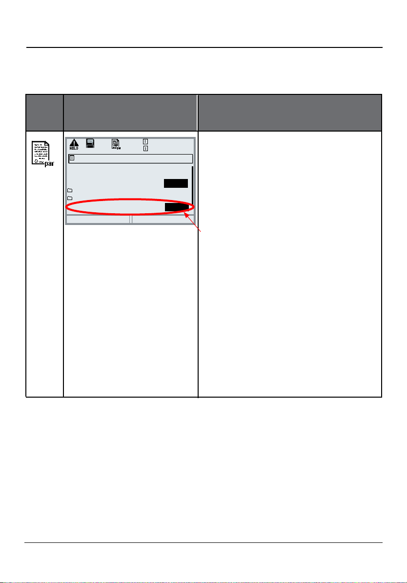
System forecast: Record on SmartMedia card
System Forecast:
RecordingonSmartMediaCard
Menu: Parameter setting / Probe control / Installation / System forecast
Menu Display System forecast: SmartMedia card
7.00 pH
Off
25.6 °C
On
On
System control (Administrator)
12/21/16 12:37 S a06 b17 c25 d33 e02 CM
12/21/16 12:37 P a09 b16 c26 d34 e02 CM
Monitoring
Edit reference profile
Tolerances
Record on card Off
Return
Record on SmartMedia card
If a SmartMedia card is installed,
probe travel times can be saved on it
(ASCII). The recording capacity is limited only by the amount of memory on
the card.
For this function, use the final menu
item in the system forecast –
"Record on card".
96
Page 97

System forecast: Messages
System Forecast: Messages
No. "System forecast" message Cause
U160 SP Pressure loss/Air sensor Air leaking uncontrolled – air sensor defective
U161 SP Probe valve not functioning Pilot valve does not switch; probe valve possibly
U162 SP Air sensor not functioning Air sensor does not switch
U163 SP Probe valve sluggish Pilot valve switches late; probe valve possibly
U164 SP Air sensor sluggish Air sensor switches late
U165 SP Limit positions interrupted Both limit positions do not switch
U166 SP Limit positions short-circuited Both limit switches are actuated (short-circuited)
U170 SP Probe stopped between end positions Probe is stuck between the limit positions
U171 SP PROCESS position sluggish Limit switch (PROCESS) reacts too late after start of
U172 SP Probe sluggish Probe sluggish (limit position is reached)
U173 SP Probe is stuck during probe travel Probe is stuck during probe travel (limit position is
U174 SP SERVICE position not functioning Limit switch (SERVICE) does not react after end of
U175 SP PROCESS position not functioning Limit switch (PROCESS) does not react after end of
U176 SP SERVICE position sluggish Limit switch (SERVICE) reacts too late after end of
U177 SP SERVICE position not functioning Limit switch (SERVICE) not functioning
U178 SP PROCESS position not functioning Limit switch (PROCESS) not functioning
U179 SP Probe instantly got stuck Probe is stuck in limit position
U188 SP General error Error not clearly assignable
does not switch
switches late
(e.g. GND missing)
probe travel
not reached)
probe travel
probe travel
probe travel
Messages are automatically reset after two correct probe movements.
97
Page 98

Setting the Uniclean 900(X)
parameters
Uniclean 900(X) Parameter Setting
Functional Capabilities
Setting Adjustable parameters Page
• Control Off, Unical 9000, Uniclean 900
• Time control Fixed interval, Week program:
Fixed interval: Select program, interval
Week program: Configuration of program flows
• Program flow Individual adaptation of program steps for:
Rinsing, Cleaning, Parking, Service
• Installation
Meas. procedures Continuous / Short-time
External control (DCS) Off, On
DCS inputs (36...39) active 10...30 V or active < 2 V
M/S input (42/43) active 10...30 V or active < 2 V
A/M input (40/41) active 10...30 V or active < 2 V
Output DCS 34 Measuring, Alarm
DCS outputs (31…34) N/O, N/C
• Sensor detection On, Off
• Immersion lock Off, Sensocheck Glass el
• Access manual control Access code required. All valves can be actuated separately.
• Probe Probe type (SensoGate, Ceramat, others)
Move time max. Adjustable; default setting 0015 s
Sealing water On, Off
Cavity rinsing Off, Interval, Continuous
Check interval On, Off (On: Entry: Check after x travels)
Maintenance interval On, Off (On: Entry: Maintenance after x travels)
Pg 99
Pg 100
Pg 108
• Media adapter (I ... III)
(up to 3 metering
pumps)
• Add. media (1 ... 2) Monitoring of medium (On, Off, Medium)
• Start-up Yes, No
• System forecast On, Off
Each:
Pump (On, Off), Medium, Displaced volume, Residual volume
98
Pg 113
Pg 88
Page 99
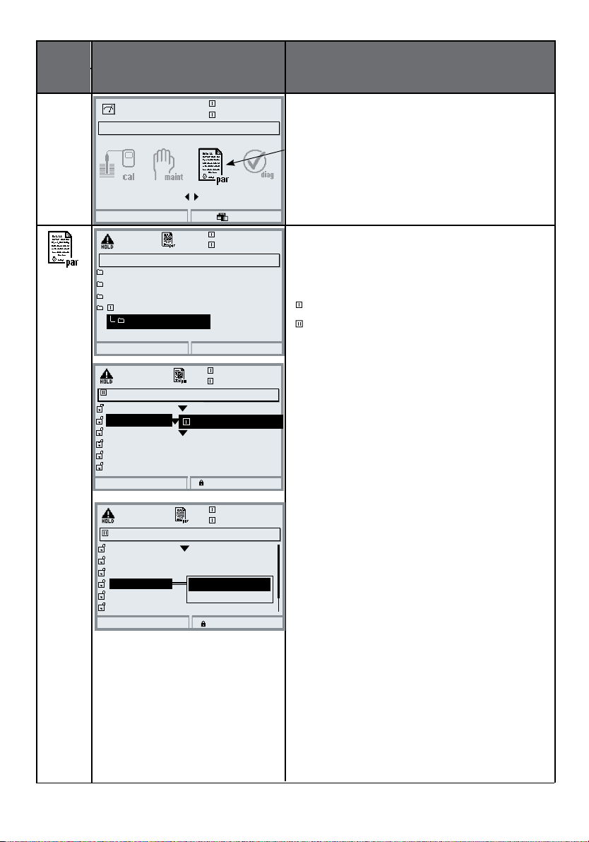
Time control (fixed interval /
week program)
Menu Display
Menu selection
Return to meas
Parameter setting (Administrator)
System control
Module FRONT 3400-011
Module BASE 3400-021
Module PHU 3400-110
Probe control
Return
Probe control (Administrator)
Control
Meas. module
Time control
Week program
Program flow
Installation
Return
Select:
Uniclean 900
Module PHU 3400-110
Week program
[enter]
Block
7.05 pH
25.6 °C
Lingua
7.05 pH
25.6 °C
OK
7.05 pH
25.6 °C
Uniclean 900
parameter setting
Open parameter setting
From the measuring mode:
Press menu key to select menu.
Select parameter setting using arrow
keys, press enter to confirm.
Select “Probe control / Uniclean 900”.
Icons to assign the measured values
displayed:
specifies module slot I
specifies module slot II
Measuring Module
Select measuring module:
Select the pH module for evaluation
with the Uniclean 900 controller (only
if equipped with more than 1 pH
module).
Probe control (Administrator)
Control
Measuring module
Cal mode
Time control
Program flow
Installation
Return
Uniclean 900
Fixed interval
Week program
Block
7.05 pH
25.6 °C
Time Control
• Fixed interval: Specify times
(000.0 h ... xxx.x h)
(Please note: 000.1 h = 6 min)
• Week program:
Specify weekday
99
Page 100
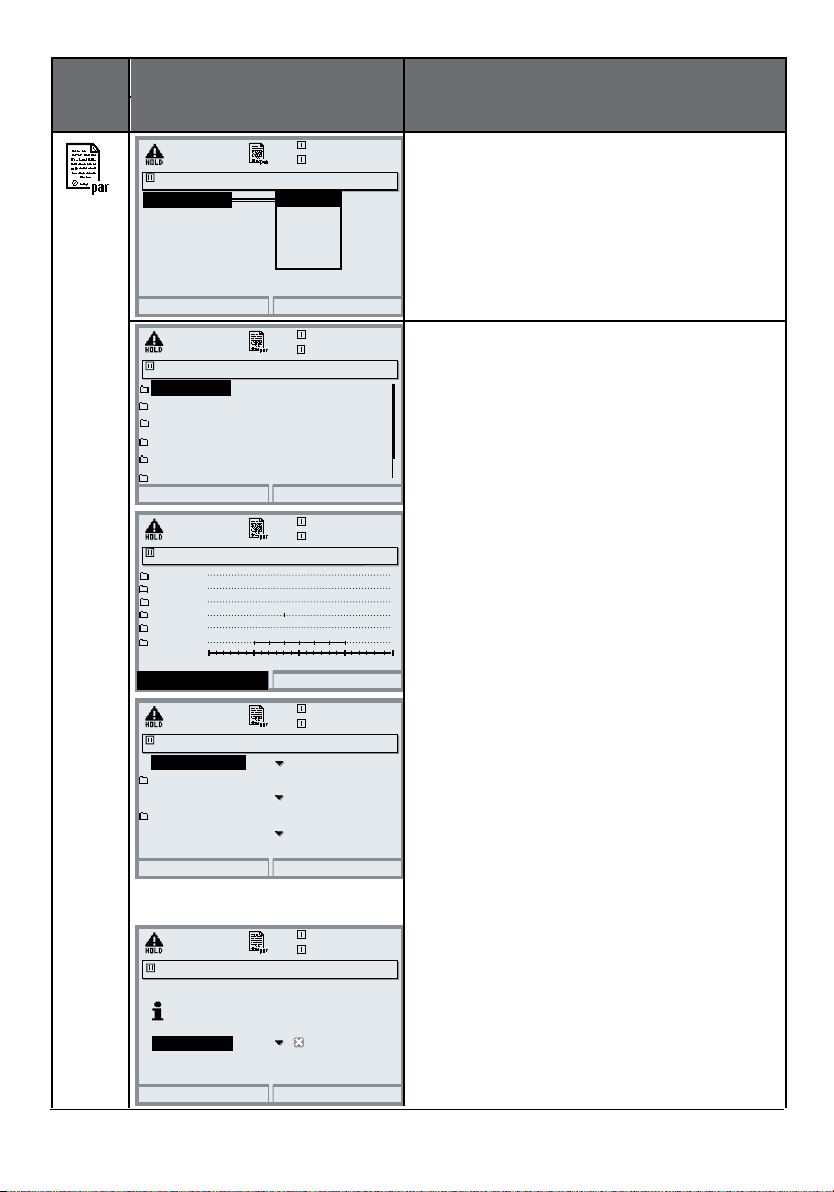
Week program
Menu Display Time control configuration
Fixed interval (Administrator)
Program
Interval
Abort
Week program (Administrator)
Monday
Tuesday
Wednesday (Today)
Thursday
Friday
Saturday
Return
Monday (Administrator)
User 2
User 1
Parking
Parking
Clean
Rinse
0:00 6:00 12:00 18:00 24:00
Return
Monday (Administrator)
01: Program
Start 06:00 End 18:00 Int. 002.0 h
02: Program
Time of start 08:00
03: Program
Return
Off
Rinse
Clean
Parking
Clean
Cal 1point
--- End ---
Weekday
7.05 pH
25.6 °C
OK
7.05 pH
25.6 °C
7.05 pH
25.6 °C
7.05 pH
25.6 °C
Time control: Fixed interval
The “Fixed interval” menu allows selection of up to three programs. An individual time interval an be assigned to
each program.
Time control: Week program
In this menu you can View, Edit, and
Copy.
View
shows the configured program
sequences over the day.
Edit
allows selection of up to 10 programs
per day and you can choose between
“Individual start” or “Interval”
(the program is executed within a start
and an end time at a specified interval).
100
Copy day (Administrator)
Copy Monday to “Weekday”
Old day is overwritten!
Weekday
Return
7.05 pH
25.6 °C
Copy
allows taking over a configured
program for another weekday.
(Further editing is possible.)
 Loading...