

Page 1
Building Automation SystemsIndustrial Automation
User Manual
easy500, easy700
Control Relay
05/04 AWB2528-1508GB
Think future. Switch to green.
Page 2

All brand and product names are trademarks or registered
trademarks of the owner concerned.
st
1
published 2004, edition date 05/04
© Moeller GmbH, 53105 Bonn
Author: Dieter Bauerfeind
Editor: Michael Kämper
Translator: Terence Osborn
All rights reserved, including those of the translation.
No part of this manual may be reproduced in any form
(printed, photocopy, microfilm or any other process) or
processed, duplicated or distributed by means of electronic
systems without written permission of Moeller GmbH, Bonn.
Subject to alteration without notice.
Page 3

Warning!
Dangerous electrical voltage!
Before commencing the installation
• Disconnect the power supply of the device.
• Ensure that devices cannot be accidentally
restarted.
• Verify isolation from the supply.
• Earth and short circuit.
• Cover or enclose neighbouring units that
are live.
• Follow the engineering instructions (AWA)
of the device concerned.
• Only suitably qualified personnel in
accordance with EN 50110-1/-2
(VDE 0105 Part 100) may work on this
device/system.
• Before installation and before touching
the device ensure that you are free of
electrostatic charge.
• The functional earth (FE) must be
connected to the protective earth (PE) or
to the potential equalisation. The system
installer is responsible for implementing
this connection.
• Connecting cables and signal lines should
be installed so that inductive or capacitive
interference does not impair the
automation functions.
• Install automation devices and related
operating elements in such a way that they
are well protected against unintentional
operation.
• Suitable safety hardware and software
measures should be implemented for the
I/O interface so that a line or wire breakage
on the signal side does not result in
undefined states in the automation
devices.
• Ensure a reliable electrical isolation of the
low voltage for the 24 volt supply. Only
use power supply units complying with
IEC 60364-4-41 (VDE 0100 Part 410) or
HD 384.4.41 S2.
• Deviations of the mains voltage from the
rated value must not exceed the tolerance
limits given in the specifications, otherwise
this may cause malfunction and dangerous
operation.
•Emergency stop devices complying with
IEC/EN 60204-1 must be effective in all
operating modes of the automation
devices. Unlatching the emergency-stop
devices must not cause restart.
• Devices that are designed for mounting in
housings or control cabinets must only be
operated and controlled after they have
been installed with the housing closed.
Desktop or portable units must only be
operated and controlled in enclosed
housings.
Moeller GmbH
Safety instructions
I
Page 4

• Measures should be taken to ensure the
proper restart of programs interrupted
after a voltage dip or failure. This should
not cause dangerous operating states even
for a short time. If necessary, emergencystop devices should be implemented.
• Wherever faults in the automation system
may cause damage to persons or property,
external measures must be implemented to
ensure a safe operating state in the event
of a fault or malfunction (for example, by
means of separate limit switches,
mechanical interlocks etc.).
II
Page 5

05/04 AWB2528-1508GB
Content
About This Manual 9
Device designation 9
Writing conventions 10
1 easy 11
Target readership 11
Proper use 11
– Improper use 11
Overview 12
Versions 15
– Type reference 17
easy operation 19
–Buttons 19
– Moving through menus and choosing values 19
– Selecting main and system menu 20
– easy Status display 21
– Status display for local expansion 21
– Advanced Status display 22
– easy LED display 22
–Menu structure 23
– Selecting or toggling between menu items 28
– Cursor display 28
– Setting values 29
1
Page 6

Content
05/04 AWB2528-1508GB
2 Installation 31
Mounting 31
Connecting the expansion device 34
Terminals 35
–Tools 35
– Cable cross-sections 35
Connecting the power supply 35
– Cable protection 35
– Supplying AC units 36
– Supplying DC units 37
Connecting the inputs 39
– Connecting easy AC digital inputs 39
– Connecting easy DC digital inputs 44
– Connecting easy DC analog inputs 46
– Connecting high-speed counters and
frequency generators 51
Connecting the outputs 53
– Connecting relay outputs 54
– Connecting transistor outputs 56
Expanding inputs/outputs 59
– Local expansion 59
– Remote expansion 60
Connecting bus systems 62
3 Commissioning 63
Switching on 63
Setting the menu language 64
easy operating modes 65
Creating your first circuit diagram 66
– Circuit diagram display 68
– From the first contact to the output coil 69
– Wiring 70
– Testing the circuit diagram 71
– Deleting the circuit diagram 73
– Fast circuit diagram entry 73
2
Page 7

05/04 AWB2528-1508GB
Content
4 Wiring with easy 75
Operation of easy 75
– Buttons for editing circuit diagrams and
function relays 75
– Operation 76
– Relay, function relays 79
– Saving and loading circuit diagrams 82
Working with contacts and relays 83
– Input and output contacts 83
– Creating and modifying connections 86
– Inserting and deleting a rung 88
– Switching with the cursor buttons 89
– Checking the circuit diagram 90
– Coil functions 91
Function relays 97
– Example with function relay timer and
counter relay 98
Analog value comparator/threshold value switch 104
– Circuit diagram display with analog value
comparator 105
– Compatibility between easy400 and easy500,
easy600 and easy700 107
– Parameter display in RUN mode 108
– Resolution of the analog inputs 108
– Function of the analog value comparator 109
Counters 117
– Function of the counter function relay 121
High-speed counters, easy-DA, easy-DC 125
– Frequency counters 125
– High-speed counter 131
Text display 137
– Wiring a text display 138
– Retention 138
– Scaling 139
– Function 139
– Text entry 140
– Character set 140
– Entering a setpoint in a display 141
3
Page 8

Content
05/04 AWB2528-1508GB
7-day time switch 143
– Parameter display and parameter set for
7-day time switch: 144
– Changing time switch channel 145
– Function of the 7-day time switch 146
Operating hours counter 149
– Value range of the operating hours counter 150
– Accuracy of the operating hours counter 150
– Function of the operating hours counter
function block 150
Timing relays 154
– Parameter display and parameter set for a
timing relay: 155
– Retention 156
– Timing relay modes 157
– Time range 157
– Function of the timing relay function block 160
– Timing relay examples 168
Jumps 171
– Function 171
– Power flow display 172
Year time switch 174
– Wiring of a year time switch 174
– Parameter display and parameter set for the
year time switch: 175
– Changing time switch channel 176
– Entry rules 176
– Function of the year time switch 178
Master reset 181
– Operating modes 182
– Function of the master reset function relay 182
4
Page 9

05/04 AWB2528-1508GB
Content
Basic circuits 183
– Negation (contact) 183
– Negation (coil) 184
– Maintained contact 184
– Series circuit 184
– Parallel circuit 185
– Parallel circuit operating like a series
connection of make contacts 186
– Parallel circuit operating like a series
connection of break contacts 187
– Two-way circuit 187
– Self-latching 188
– Impulse relay 189
– Cycle pulse on rising edge 190
– Cycle pulse on falling edge 190
Example circuits 191
– Star-delta starting 191
– 4x shift register 193
– Running light 197
– Stairwell lighting 199
5easy Settings 203
Password protection 203
– Password setup 204
– Selecting the scope of the password 205
– Activating the password 206
– Unlocking easy 207
Changing the menu language 209
Changing parameters 210
– Adjustable parameters for function relays 211
Setting date, time and daylight saving time 213
– Setting the time 213
– Setting summer time start and end 214
– Setting summer time start and end 215
– Summer time start and end, setting the rule 215
Activating debounce (input delay) 222
– Activating debounce (input delay) 223
– Deactivating debounce (input delay) 223
5
Page 10

Content
05/04 AWB2528-1508GB
Activating and deactivating the P buttons 224
– Activating the P buttons 224
– Function of the P buttons 224
– Deactivating the P buttons 225
Startup behaviour 225
– Setting the startup behaviour 225
– Behaviour when the circuit diagram is deleted 226
– Behaviour during upload/download to
card or PC 227
– Possible faults 227
– Card mode behaviour 227
Setting the cycle time 229
Retention (non-volatile data storage) 230
– Permissible markers and function relays 230
– Setting retentive behaviour 230
– Deleting retentive actual values 232
– Transferring retentive behaviour 232
– Changing the operating mode or
the circuit diagram 233
– Changing the startup behaviour in
the SYSTEM menu 233
Displaying device information 234
6
Page 11

05/04 AWB2528-1508GB
Content
6Inside easy 235
easy circuit diagram cycle 235
– easy operation and effects on
circuit diagram creation 236
Delay times for inputs and outputs 238
– Delay times with easy-DA and
easy-DC basic units 238
– Delay time with easy-easy-AB,
easy-AC basic units 240
– Delay times for the analog inputs of easy-AB,
easy-DA and easy-DC 241
Monitoring of short-circuit/overload with
EASY..-D.-T.. 242
Expanding easy700 243
– How is an expansion unit recognised? 244
– Transfer behaviour 244
– Function monitoring of expansion units 245
Saving and loading circuit diagrams 246
– EASY…-..-..X 246
– Interface 246
Memory card 248
– Compatibility with EASY-M-8K, EASY-M-16K
memory cards 248
– Loading or saving circuit diagrams 249
EASY-SOFT-BASIC 252
Overview with stand-alone display/operating unit 253
Device version 254
7 What Happens If ...? 255
Messages from the easy system 255
Possible situations when creating circuit
diagrams 256
Event 258
7
Page 12

Content
05/04 AWB2528-1508GB
Appendix 259
Dimensions 259
Technical Data 262
– General 262
– Special approvals 264
– Power supply 265
– Inputs 266
– Relay outputs 272
– Transistor outputs 274
List of the function relays 277
– Usable contacts 277
– Available function relays 278
– Names of relays 279
– Names of function relay 279
– Name of function block inputs (constants,
operands) 280
Compatibility of function relay parameters 281
– Parameter display of analog value comparator 281
– Parameter display of counters 281
– Parameter display of 7-day time switch 282
– Parameter display of timing relay 282
Glossary 283
Index 287
8
Page 13

05/04 AWB2528-1508GB
About This Manual
This manual describes the installation, commissioning and
programming (circuit diagram generation) of the easy500
and easy700 control relay.
Specialist electrical training is needed for commissioning and
creating circuit diagrams. When active components such as
motors or pressure cylinders are controlled, parts of the
system can be damaged and persons put at risk if the device
is connected or programmed incorrectly.
Device designation This manual uses the following abbreviated designations for
different easy models:
easy412 for all EASY412-..-... devices
EASY512-..-..., EASY7..-..-...
Type designation of the control relay, the dots represent
placeholders for all characters used.
easy500 for
EASY512-AB..., EASY512-AC..., EASY512-DA... and
EASY512-DC...
easy600 for all EASY61.-AC-RC(X), EASY62.-DC-TC(X)
easy700 for
EASY719-AB..., EASY719-AC..., EASY719-DA..., EASY719DC... and EASY721-DC...
easy-AB for
EASY512-AB...
EASY719-AB...
easy-AC for
EASY512-AC...
EASY618-AC-RE and EASY719-AC...
easy-DA for
EASY512-DA...
EASY719-DA...
9
Page 14

About This Manual
easy-DC for
EASY512-DC...
EASY6..-DC..., EASY719-DC... and EASY721-DC...
easy-E for
EASY2.., EASY618-AC-RE, EASY618-DC-RE and EASY620DC-TE
Writing conventions Symbols used in this manual have the following meanings:
X indicates actions to be taken.
Attention!
h
i
Warns of a hazardous situation that could result in
damage to the product or components.
Caution!
Warns of the possibility of serious damage and slight
injury.
05/04 AWB2528-1508GB
10
j
h
Warning!
Warns of the possibility of a hazardous situation that
could result in major damage and serious or fatal injury or
even death.
Indicates interesting tips and additional information
For greater clarity, the name of the current chapter is shown
in the header of the left-hand page and the name of the
current section in the header of the right-hand page. Pages
at the start of a chapter and empty pages at the end of a
chapter are exceptions.
Page 15

05/04 AWB2528-1508GB
1easy
Target readership easy must only be installed and connected up by trained
electricians or other persons who are familiar with the
installation of electrical equipment.
Specialist electrical training is needed for commissioning and
creating circuit diagrams. When active components such as
motors or pressure cylinders are controlled, parts of the
system can be damaged and persons put at risk if easy is
connected or programmed incorrectly.
Proper use easy is a programmable switching and control device and is
used as a replacement for relay and contactor control
circuits. easy may only be operated when it has been
correctly and properly installed.
• easy is designed to be installed in an enclosure, switch
cabinet or service distribution board. Both the power feed
and the signal terminals must be laid and covered so as to
prevent accidental contact.
• The installation must comply with regulations for
electromagnetic compatibility (EMC).
• The starting up of easy should not cause any hazards
arising from controlled devices, such as unexpected motor
startups or power ups.
Improper use
easy should not be used as a substitute for safety-related
controls such as burner or crane controls, emergency-stop or
two-hand safety controls.
11
Page 16
easy
Overview
05/04 AWB2528-1508GB
2
3
4
1
2
12
10
5
P
O
W
B
U
S
P
O
W
E
R
C
O
M
-E
R
R
A
D
R
ERR
6
7
8
MS
NS
9
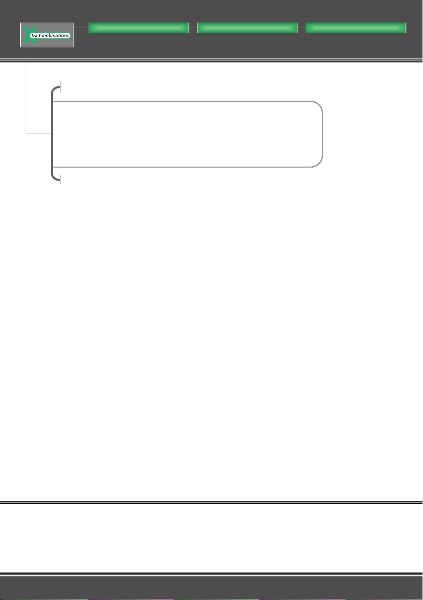
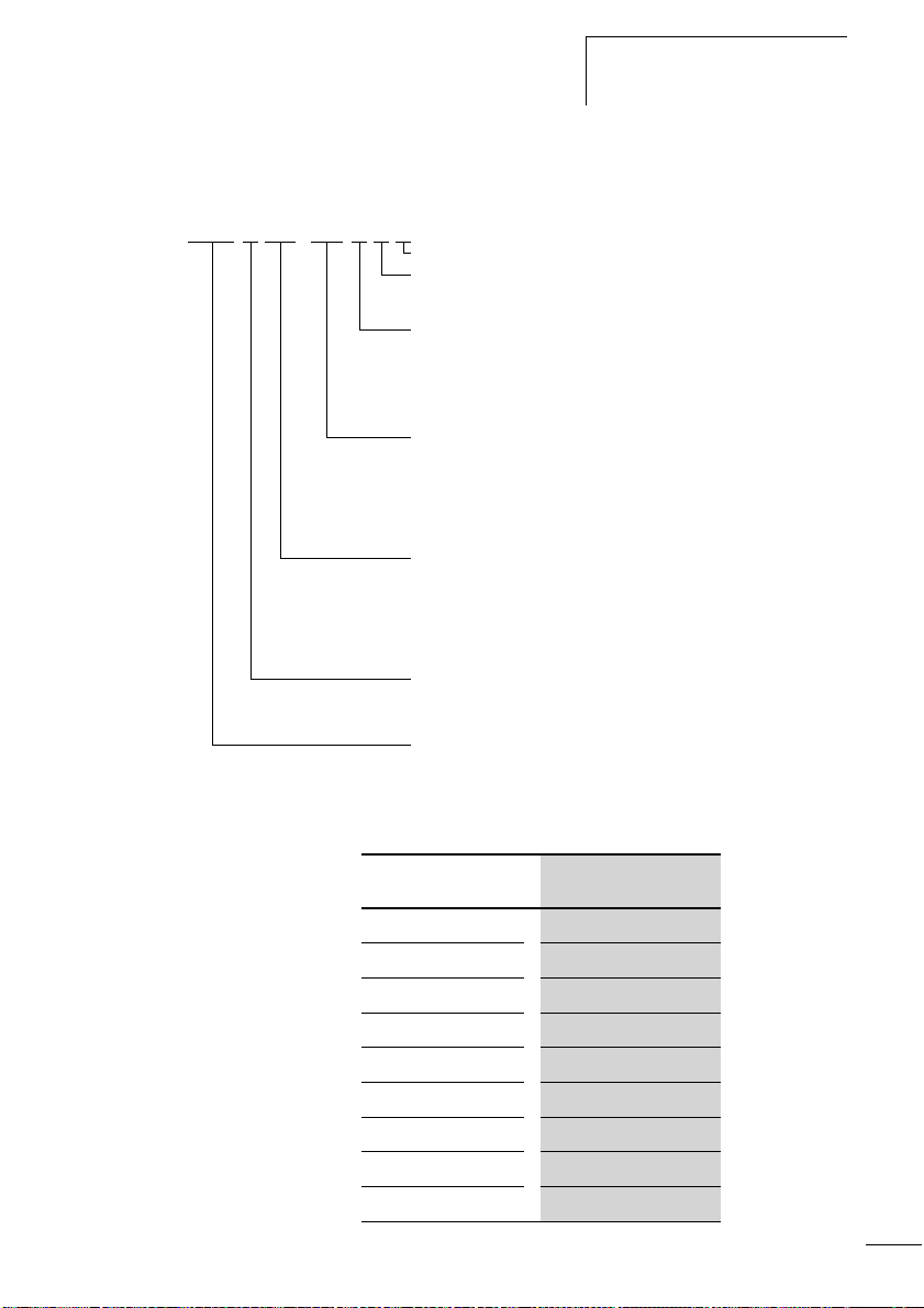
Figure 1: easy basic units and expansion devices
Page 17

05/04 AWB2528-1508GB
Overview
Legend for figure 1:
a easy500 basic unit
b easy600 I/O expansion
c EASY202-RE output expansion
d EASY200-EASY coupling device
e EASY-LINK-DS data connector
f EASY204-DP PROFIBUS-DP slave gateway
g EASY205-ASI AS-Interface slave gateway
h EASY221-CO CANopen gateway
i EASY222-DN DeviceNet gateway
j easy700 basic unit
easy is an electronic control relay with logic functions, timer,
counter and time switch functions. It is also a control and
input device in one that can perform many different tasks in
domestic applications as well as in machine building and
plant construction.
Circuit diagrams are connected up using ladder diagrams,
and each element is entered directly via the easy display. For
example, you can:
• Connect make and break contacts in series and in parallel
• Connect output relays and markers,
• Use outputs as relays, impulse relays or latching relays
• Use multi-function timing relays with different functions
• Use up and down counters,
• Count high-speed counter pulses
• Measure frequencies
• Process analog inputs, easy-AB, easy-DA, easy-DC,
(EASY512..: two analog inputs, easy700: four analog
inputs)
• Display any texts with variables, enter setpoints
• Use year time switches, 7-day time switches,
EASY…-..-.C(X),
• Count operating hours (four retentive operating hours
counters integrated)
• Track the flow of current in the circuit diagram
• Load, save and password-protect circuit diagrams
13
Page 18

easy
05/04 AWB2528-1508GB
If you prefer to wire up easy from a PC, then use EASY-SOFTBASIC. EASY-SOFT-BASIC allows you to create and test your
circuit diagram on the PC. EASY-SOFT-BASIC is also used to
print out your circuit diagram in DIN, ANSI or easy format.
14
Page 19
05/04 AWB2528-1508GB
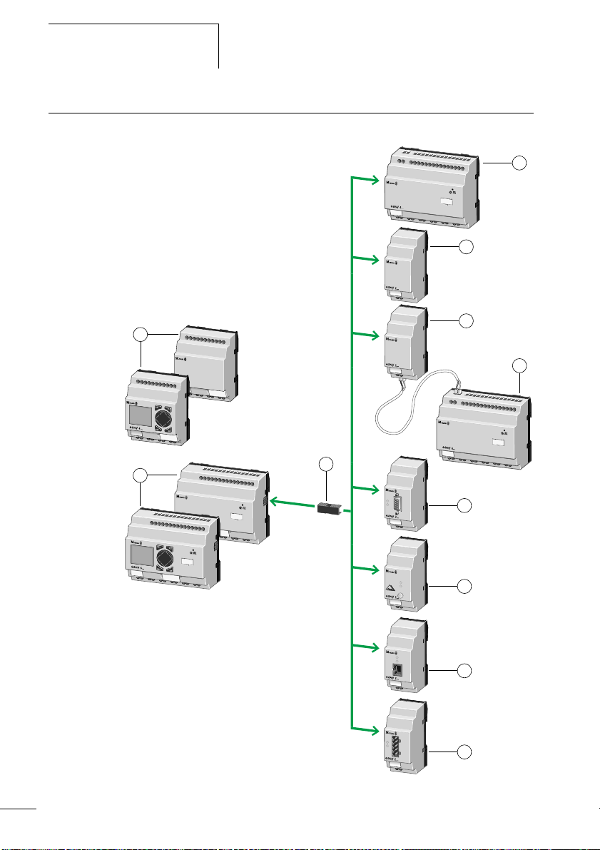
Versions easy basic units at a glance
Overview
햸
햲
DEL
DEL
ESC
ESC
ALT
OK
햳
ALT
OK
Figure 2: Versions
a Power supply
b Inputs
c Status LED
d Buttons
e Interface socket for memory card or PC connection
f Outputs
g LCD display
햴
햵
햶
햷
15
Page 20
easy
05/04 AWB2528-1508GB
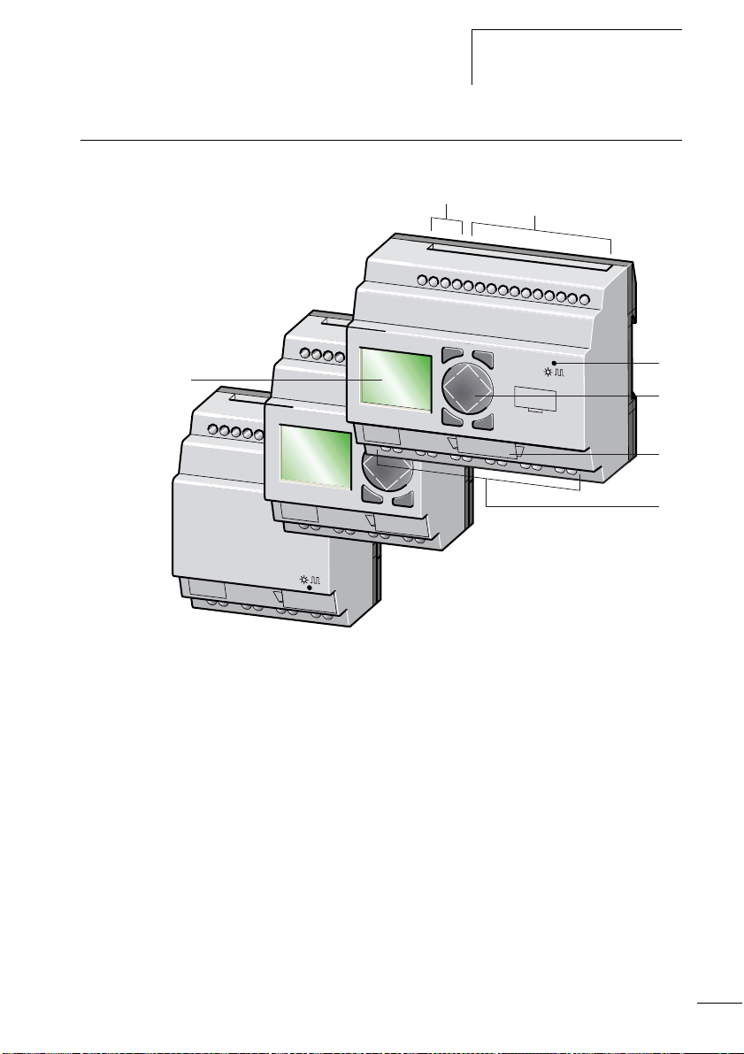
easy basic units with stand-alone MFD-80.., MFD-CP4-500
HMI unit
1
3
4
3
2
Figure 3: Overview with stand-alone HMI unit
a easy500 basic units
b easy700 basic units
c MFD device
d Power supply/communication module with MFD-CP4-500
interface cable
16
Page 21
05/04 AWB2528-1508GB
EASY-x x x -x x-x x x
Overview
Type reference
LCD display: X = No display
Time switch: C = Available; E = Expansion
Output type:
R = Relay (max. 8 A)
T = Transistor (0.5 A, parallel connection possible up to 2 A)
Supply voltage, device and inputs
AB = 24 V AC (2, (4) inputs, also usable as 0 to 10 V analog inputs)
AC = 100, 120, 230, 240 V AC
DC = 24 V DC (2 (4) inputs, also usable as 0 to 10 V analog inputs)
DA = 12 V DC (2 (4) inputs, also usable as 0 to 10 V analog inputs)
Number of inputs/outputs (+ expansion)
12 = 8 I/4 O
18 = 12 I/6 O
19 = 12 I/6 O + expansion
20 = 12 I/8 O
21 = 12 I/8 O + expansion
Rating class (RC) and space unit (SU)
2 = 35.5 mm (SU)
4, 5 = 71.5 mm (4 SU), RC = 4 or 5
6, 7= 107.5 mm (6SU), RC = 6 or 7
easy control relay
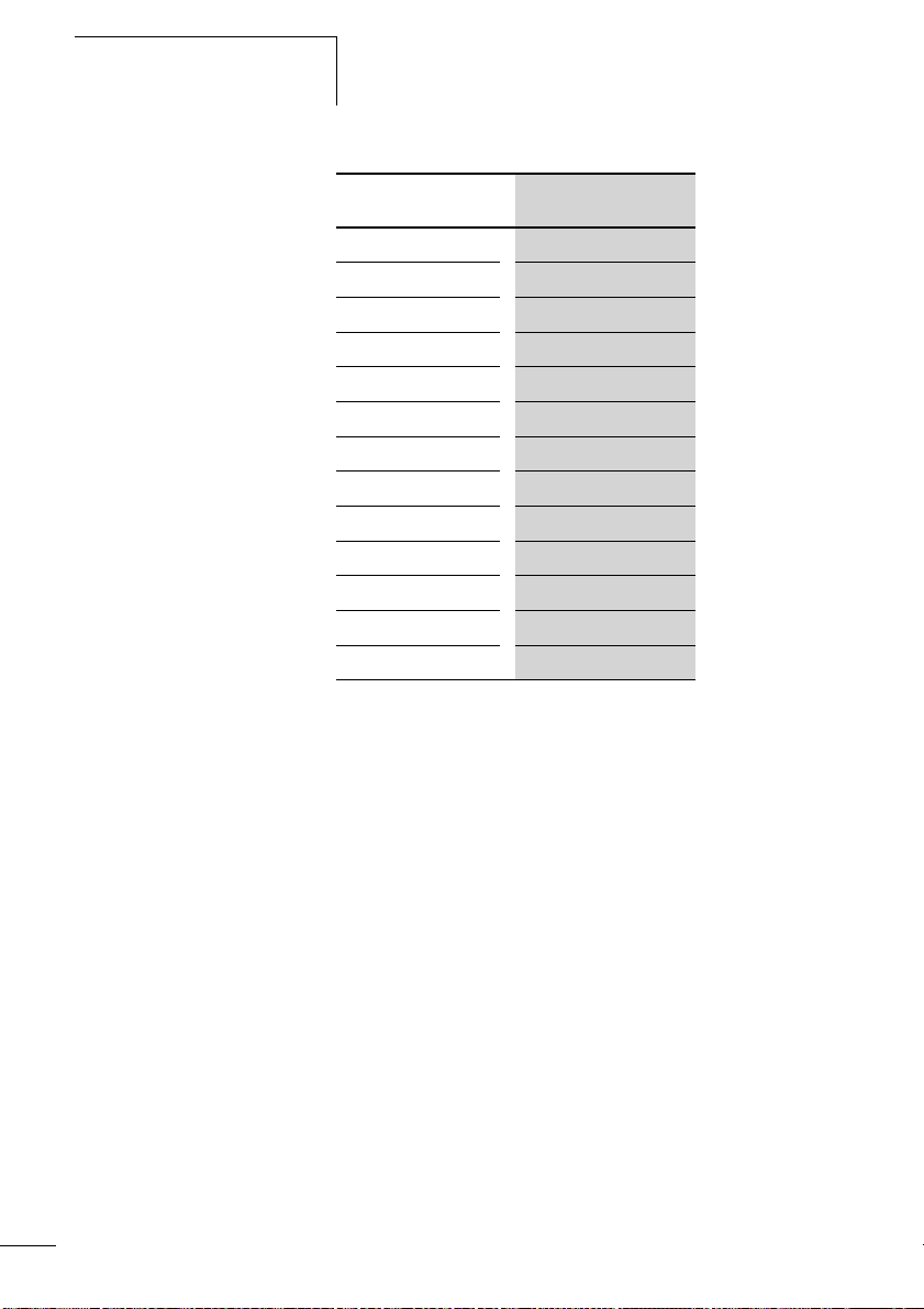
Table 1: Overview of comparable easy400 types with easy500
and easy600 with easy700
easy400, easy600 easy500, easy700
– EASY512-AB-RC
– EASY512-AB-RCX
EASY412-AC-R EASY512-AC-R
EASY412-AC-RC EASY512-AC-RC
EASY412-AC-RCX
EASY512-AC-RCX
EASY412-DA-RC EASY512-DA-RC
EASY412-DA-RCX EASY512-DA-RCX
EASY412-DC-R EASY512-DC-R
EASY412-DC-RC EASY512-DC-RC
17
Page 22
easy
05/04 AWB2528-1508GB
easy400, easy600 easy500, easy700
EASY412-DC-RCX
EASY412-DC-TC EASY512-DC-TC
EASY412-DC-TCX EASY512-DC-TCX
– EASY719-AB-RC
– EASY719-AB-RCX
EASY619-AC-RC
EASY619-AC-RCX EASY719-AC-RCX
– EASY719-DA-RC
– EASY719-DA-RCX
EASY619-DC-RC EASY719-DC-RC
EASY619-DC-RCX EASY719-DC-RCX
EASY621-DC-TC EASY721-DC-TC
EASY621-DC-TCX EASY721-DC-TCX
EASY512-DC-RCX
EASY719-AC-RC
18
Page 23
05/04 AWB2528-1508GB
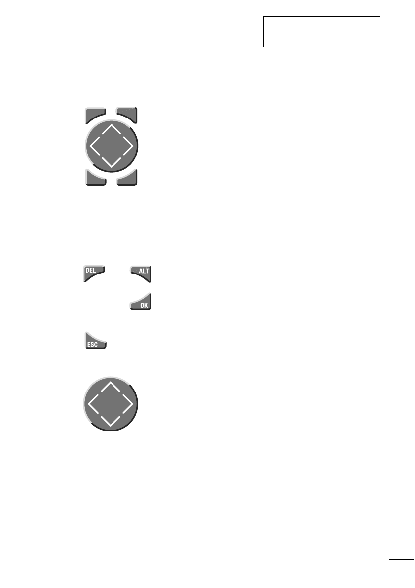
easy operation Buttons
Overview
DELDELDELDELDELDELDELDELDELDEL
ESC
and
ALT
OK
DEL: Delete object in circuit diagram
ALT: Special functions in circuit diagram, Status display
Cursor buttons
úíÍÚ:
Move cursor
Select menu items
Set contact numbers, contacts and values
OK: Next menu level, Save your entry
ESC: Previous menu level, Cancel
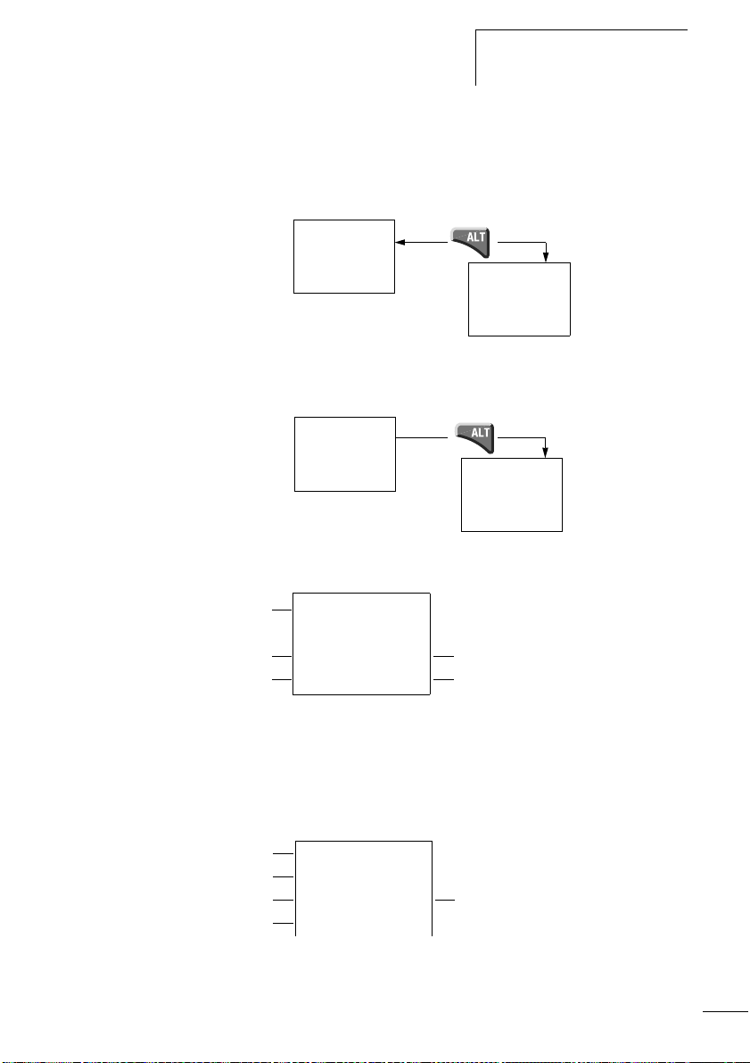
Moving through menus and choosing values
Show System menu
Go to next menu level
Select menu item
Store your entry
Return to last menu level
Cancel your entry since the last OK
ÍÚ
Change menu item
Change value
Change position
úí
P button function (if enabled):
ú
Input P1
í
Input P3
Í
Ú
Input P2
Input P4
19
Page 24
easy
05/04 AWB2528-1508GB
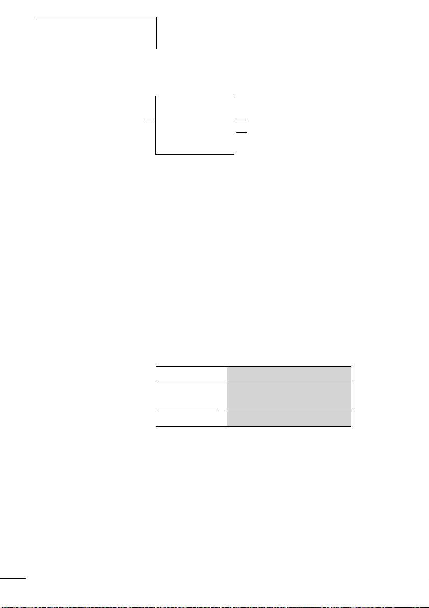
Selecting main and system menu
Status display
easy500: 8 inputs, 4 outputs
Current selection flashes in
the easy menu
Clock menu on
devices with clock
I .2..5.....
1.2
MO 02:00
RS
..34 . RUN
MO
.2 6..
PROGRAM...
STOPå RUN
PARAMETER
INFO...
SET CLOCK
1st menu level
Main menu
P-
and
No
password
SECURITY...
SYSTEM...
LANGUAGE...
1st menu level
easy500 or easy700
System menu
SECURITY...
SYSTEM...
LANGUAGE...
CONFIGURATOR
The CONFIGURATOR menu
appears if a configurable
expansion module is connected
such as EASY204-DP (Profibus-DP
bus gateway)
20
Page 25
05/04 AWB2528-1508GB
Overview
Toggling between weekday, time display and date display
(only on devices with clock)
.2..5.......
MO 11:50
..34 RUN
P-
.2..5.......
01.04.2004
..34 RUN
easy Status display
.2..5.......
MO 11:50
Q ..34..STOP
Inputs
1.......9...
RS AC P-
Weekday/Time or Weekday/Date
Outputs RUN/STOP mode
MO 10:42
1.....7. RUN
On: 1, 2, 3, 4
/Off:…
P-
.2..5......
P-
01.04.2002
Q ..34..STOP
easy500: input 1 to 8,
easy700: input 1 to 12
easy500: output 1 to 4,
easy700: output 1 to 6 or 8
P-
Status display for local expansion
Inputs
Expansion
Weekday/Time or Weekday/Date
Outputs
1.......9...
RS AC PMO 10:42
1.....7. RUN
On: 1, 2, 3, 4/Off:…
RS = Expansion functioning correctly
21
Page 26
easy
Advanced Status display
12...6.89...
Retention/Debounce AC expansion ok/P buttons
: Retention switched on
RE
: Debounce switched on
I
: AC expansion functioning correctly
AC
: DC expansion functioning correctly
DC
: Bus coupling module detected
GW
RE I ACP-
17.03.04 ST
123.5.78 RUN
Startup behaviour
GW flashes: Only easy200-easy detected. I/O expansion not detected.
17.03.04 Display of actual device date
: When the power supply is switched on, easy switches to STOP mode
ST
easy LED display
easy512-..-..X, easy700 and easy-E feature an LED on the
front indicating the status of the power supply as well as
whether RUN or STOP mode is active (a figure 2,
page 15).
05/04 AWB2528-1508GB
22
LED OFF No power supply
LED continuously
Power supply present, STOP mode
lit
LED flashing Power supply present, RUN mode
Page 27
05/04 AWB2528-1508GB
Main menu
Overview
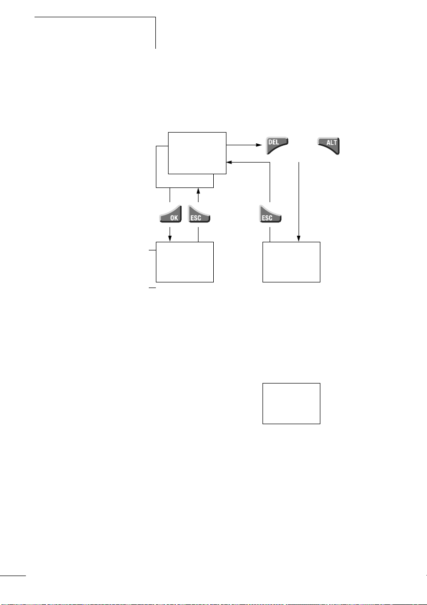
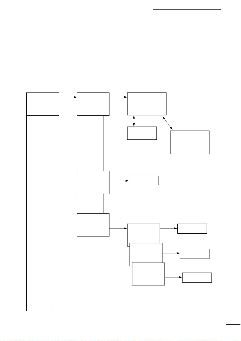
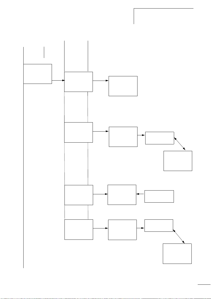
Menu structure
Main menu without password protection
X You access the main menu by pressing OK.
STOP: Circuit diagram
display
PROGRAM....Æ
STOP å RUN
PARAMETER
INFO... æ
SET CLOCK..
The
arrows
indicate
that there
are more
than four
menus.
PROGRAM...
DELETE PROG
CARD
PROGRAM...
DELETE PROG
CARD...
PROGRAM...
DELETE PROG
CARD...
Circuit diagram
SAVE
CANCEL
DELETE ?
DEVICE-CARD
CARD-DEVICE
DELETE CARD
DEVICE-CARD
CARD-DEVICE
DELETE CARD
DEVICE-CARDE
CARD-DEVICE
DELETE CARD
Parameter
display
Parameters
REPLACE ?
REPLACE ?
DELETE ?
23
Page 28
easy
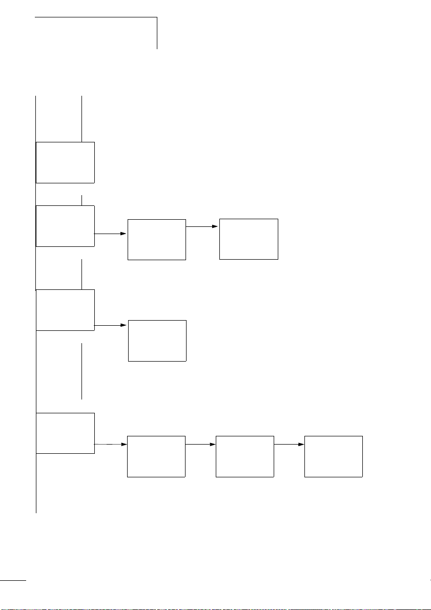
Mai
05/04 AWB2528-1508GB
n menu
PROGRAM....Æ
STOP RUN å
PARAMETER
INFO... æ
SET CLOCK..
PROGRAM....Æ
STOP RUN å
PARAMETER...
INFO... æ
SET CLOCK..
PROGRAM....Æ
STOP RUN å
PARAMETER...
INFO... æ
SET CLOCK..
Parameter display
T1 X S +
T2 Ü M:S +
C1 N +
O1 +
T1 X S +
S1 10.000
S2 +0
T:
Information display of the device
DC TC LCD
OS: 1.00.027
CRC: 02752
PROGRAM...
STOP RUN Æ
PARAMETER
INFO...
SET CLOCK.æ
24
SET CLOCK..
SUMMER
TIME..
Display for date and time
setting
HH:MM --:--
DD.MM --.--
YEAR ____
HH:MM 14:23
DD.MM 17.03
YEAR 2004
Page 29
05/04 AWB2528-1508GB
Mai
Overview
n menu
PROGRAM...
STOP RUN Æ
PARAMETER...
INFO...
SET CLOCK.æ
SET CLOCK..
SUMMER TIME.
SET CLOCK..
SUMMER TIME.
Only one selection is possible.
NONE åÆ
RULE...
EU
GB æ
US
NONE Æ
RULE...
EU
GB æ
US
SUMMER START
SUMMER END
AM --Æ
WD: --
-DD.MM:00.00æ
HH:MM:00:00
DIFF: 0:00
SET CLOCK..
SUMMER TIME.
SET CLOCK..
SUMMER TIME.
NONE Æ
RULE... å
EU
GB æ
US
NONE Æ
RULE... å
EU
GB æ
US
SUMMER START
SUMMER END
SUMMER START
SUMMER END
AM --Æ
WD: --
-DD.MM:00.00æ
HH:MM:00:00
DIFF: 0:00
25
Page 30
easy
05/04 AWB2528-1508GB
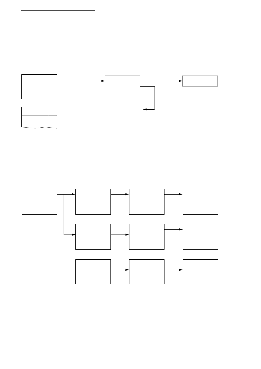
Main menu with password protection
Main menu
PASSWORD.. Æ
STOP RUN å
PARAMETER...
INFO... æ
SET CLOCK..
PASSWORD...
STOP RUN å
System menu
SECURITY...
SYSTEM...
LANGUAGE...
CONFIGURATOR
Password setup
Change/
delete
password
easy
Example:
Password only
on program
easy System menu
The System menu is accessed by simultaneously pressing
DEL and ALT.
PASSWORD...
RANGE...
ACTIVATE PW
CHANGE PW
Password entryUnlocking
Password
Status display
Password entry
Correct entry
ENTER PASSW:
XXXX
ENTER PASSW:
XXXX
DELETE ALL
Four wrong entries
(if enabled)
CHANGE PW
ACTIVATE PW
CHANGE PW
ACTIVATE PW
26
PASSWORD...
RANGE...
PROGRAM å Æ
PARAMETER
TIME
MODE æ
INTERFACE
DEL PROG
PROGRAM å Æ
PARAMETER å
TIME å
MODE æ
INTERFACE å
DEL PROG å
Page 31

05/04 AWB2528-1508GB
System menu
Overview
SECURITY...
SYSTEM...
LANGUAGE...
CONFIGURATOR
SECURITY...
SYSTEM...
LANGUAGE...
CONFIGURATOR
SECURITY...
SYSTEM...
LANGUAGE...
CONFIGURATOR
DEBOUNCE å
P-BUTTONS
RUN MODE å
CARD MODE
ENGLISH Æ
DEUTSCH å
FRANCAIS
ESPANOL æ
ITALIANO
PORTUGUES
NEDERLANDS
SVENSKA
POLSKI
TURKCE
CESKY
MAGYAR
Only one selection is possible.
The further menus depend on the
connected expansion device
27
Page 32

easy
PROGRAM...
STOP
PARAMETER
INFO
05/04 AWB2528-1508GB
Selecting or toggling between menu items
Í Ú
Cursor
Select or toggle
Cursor display
HH:MM '4:23
DD.MM 17.03
YEAR 2004
HH:MM 14:23
DD.MM 17.03
YEAR 2004
The cursor flashes.
Full cursor
• Move cursor with
• in circuit diagram also with
Ê/:
úí,
Í Ú
Value M/M
• Change position with úí
• Change values with Í Ú
Flashing values/menus are shown in grey in this manual.
28
Page 33

05/04 AWB2528-1508GB
Overview
Setting values
HH:MM 14:23
DD.MM 17.03
YEAR 2004
Values
Digits
Current value at the
position (can be
changed, Cursor = 3)
Select value
Í Ú
Select digit úí
Change value at digit ÍÚ
Store entries
Retain previous value
29
Page 34

05/04 AWB2528-1508GB
30
Page 35

05/04 AWB2528-1508GB
2 Installation
easy must only be installed and wired up by trained
electricians or other persons familiar with the installation of
electrical equipment.
Danger of electric shock
j
Mounting Install easy in a control cabinet, service distribution board or
Never carry out electrical work on the device while the
power supply is switched on.
Always follow the safety rules:
• Switch off and isolate
• Secure against reclosing
• Ensure that the device is no longer live
• Cover adjacent live parts
easy is installed in the following order:
• If necessary connect devices together
• Mounting
• Wiring up the inputs
• Wiring up the outputs
• Connecting the power supply
in an enclosure so that the power feed and terminal
connections cannot be touched accidentally during
operation.
Clip easy onto a DIN EN 50022 top-hat rail or fix easy in
place using fixing brackets. easy can be mounted vertically
or horizontally.
h
When using easy with expansion units, connect the
expansion concerned before mounting (a page 34).
31
Page 36

Installation
05/04 AWB2528-1508GB
For ease of wiring, leave a gap of at least 30 cm between
easy terminals and the wall or adjacent devices.
30
30
30
Figure 4: Clearances to easy
30
1
Mounting on top-hat rail
X Hook easy to the top edge of the top-hat rail and hinge
into place while pressing down slightly. Press the device
lightly downwards and against the top-hat rail until it
snaps over the lower edge of the top-hat rail.
easy will clip into place and will be secured by the built-in
spring mechanism.
X Check that the device is seated firmly.
easy is mounted vertically on a top-hat rail in the same way.
2
32
Page 37

05/04 AWB2528-1508GB
Mounting
Using a mounting plate
Mounting on a mounting plate requires the use of fixing
brackets which are fixed to the back of easy. The fixing
brackets are available as an accessory.
easy600 and easy700: Fasten each device with at least three
fixing brackets.
EASY200-EASY: easy500: easy600, easy700:
Figure 5: Using a mounting plate
33
Page 38

Installation
Connecting the expansion device
05/04 AWB2528-1508GB
1
2
34
4
3
Figure 6: Connecting expansion units
Page 39

05/04 AWB2528-1508GB
X Open the easy-LINK connections on the side of both easy
devices.
X Fit the easy-LINK data connector EASY-LINK-DS in the
opening provided on the expansion device.
X Plug the devices together.
X Proceed in the reverse order to dismantle the device.
Terminals Tools
Slot-head screwdriver, width 3.5 mm, tightening torque
0.6 Nm.
Cable cross-sections
• Solid: 0.2 to 4 mm
• Flexible with ferrule: 0.2 to 2.5 mm
Terminals
2
2
Connecting the power supply
h
The required connection data for device types , easy-AB
with 24 V AC, easy-AC with standard voltages of 100 V
AC, easy-DA with 12 V DC and easy-DC with 24 V DC are
provided in the section “Technical Data”, page 262.
The easy500 and easy700 basic units run a system test for
two seconds after the power supply has been switched on.
Either RUN or STOP mode will be activated after these two
seconds, depending on the default setting.
Cable protection
Connect on easy cable protection (F1) rated for at least 1 A
(slow).
35
Page 40

Installation
05/04 AWB2528-1508GB
Supplying AC units
Supplying AC basic units
EASY…-AB-RC(RCX), EASY…-AC-R(RC, RCX)
L
N
F1
NNL
Figure 7: Power supply on the AC basic units
Supplying AC expansion units
EASY…-AC-.E
36
L
N
F1
E+
R1
E-
...
R12
NNL
Figure 8: Power supply on the AC expansion units
Page 41

05/04 AWB2528-1508GB
j
h
Connecting the power supply
Applies to easy-AC devices with a power supply
greater than 24 V AC:
• The voltage terminals for phase L and neutral conductor
N have been reversed.
• This enables the easy interface (for memory card or PC
connection) to have the full connection voltage of the
phase conductor (100 to 240 V AC).
• There is a danger of electric shock if the connection at
the easy interface is not properly connected or if
conductive objects are inserted into the socket.
Attention!
A short current surge will be produced when switching on
for the first time. Do not switch on easy by means of reed
contacts since these may burn or melt.
Supplying DC units
Supplying DC basic units
EASY…-DA-RC(X), EASY…-DC-R(RC,RCX)
L01⫹
L01⫺
F1
+...V
DC : +24 V
DA : +12 V
Figure 9: Power supply on the DC basic units
0 V0 V
37
Page 42

Installation
05/04 AWB2528-1508GB
Supplying DC expansion units
EASY…-DC-.E
L01+
L01-
F1
h
h
R1
E-
E+
Figure 10: Power supply on the DC expansion units
...
R12
0V0V24V
24 V
easy-DC and easy-DA are protected against reverse
polarity. To ensure that easy works correctly, ensure that
the polarity of each terminal is correct.
Cable protection
Connect on easy a cable protection (F1) rated for at least 1 A
(slow).
When easy is switched on for the first time, its power
supply circuit behaves like a capacitor. Use an appropriate
device for switching on the power supply and do not use
any reed relay contacts or proximity switches.
38
Page 43

05/04 AWB2528-1508GB
Connecting the inputs easy inputs switch electronically. Once you have connected
a contact via an input terminal, you can reuse it as a contact
in your easy circuit diagram as often as you like.
L
+24 V
S1
Connecting the inputs
i
N
0 V
Figure 11: Connecting the inputs
Connect to the easy input terminals contacts such as
pushbuttons, switches, relay or contactor contacts, proximity
switches (three-wire).
Connecting easy AC digital inputs
Caution!
Connect the inputs for AC devices in compliance with the
safety regulations of the VDE, IEC, UL and CSA. Use the
same phase conductor for the input power feed, otherwise
easy will not detect the switching level and may be
damaged or destroyed by overvoltage.
I1
I1 i1
39
Page 44

Installation
05/04 AWB2528-1508GB
Connecting easy AC digital inputs on the basic unit
L
N
F1
LNN
l1 I2 I7
Figure 12: Connecting easy-AC and easy-AB digital inputs
Connecting AC digital inputs on the expansion device
L
N
F1
R10R9R8R7R6R5R4R3R2R1E+ E-
R11
R12 NNL
Figure 13: Connecting EASY...-AC-E digital inputs
40
Page 45

05/04 AWB2528-1508GB
Connecting the inputs
Table 2: easy-AB input signal values
Input signal voltage range Input current
OFF signal ON signal
easy500/
easy700
easy700 I9, I10
easy500/
easy700
easy700 I9 to I12 0.5 mA at 230 V AC/
easy600 R1 to
I1 to I6 0 to 6 V AC 14 to 26.4 V AC 4 mA at 24 V AC
I7, I8 greater than 7 V AC
or greater than
9.5 V DC
14 to 26.4 V AC 4 mA at 24 V AC
I11, I12 greater than 7 V AC
or greater than
9.5 V DC
Table 3: easy-AC input signals
Input signal voltage range Input current
OFF signal ON signal
I1 to I6 0 to 40 V 79 to 264 V 0.5 mA at 230 V AC/
I7, I8
R12
2 mA with 24 V AC and
24 V DC
2 mA with 24 V AC and
24 V DC
0.25 mA at 115 V AC
6 mA at 230 V AC/4 mA
at 115 V
0.25 mA at 115 V AC
Cable lengths
Severe interference can cause a “1” signal on the inputs
without a proper signal being applied. Observe therefore the
following maximum cable lengths:
I1 to I6 40 m without additional circuit
I7, I8 100 m without additional circuit
I9 to I12 40 m without additional circuit
R1 to R12
41
Page 46

Installation
05/04 AWB2528-1508GB
For longer lengths connect in series a diode (e.g. 1N4007)
for 1 A, min. 1000 V reverse voltage, to the easy input.
Ensure that the diode is pointing towards the input as shown
in the circuit diagram, otherwise easy will not detect the
1 state.
L
N
F1
h
i
LNN
Figure 14: AC input with suppression diode for easy-AC and
easy-AB
easy-AC:
Inputs I7 and I8 have a higher input current on the easy-AC.
Neon bulbs with a maximum residual current of 2 mA/1 mA
at 230 V/115 V can be connected to I7 and I8.
Always use neon bulbs that are operated with a separate
N connection.
Caution!
Do not use reed relay contacts at I7, I8. These may burn or
melt due to the high inrush current of I7, I8.
Two-wire proximity switches have a residual current with the
“0” state. If this residual current is too high, the easy input
may only detect a “1” signal.
Therefore, use inputs I7 and I8. An additional input circuit is
required if more inputs are used.
I1
42
Page 47

05/04 AWB2528-1508GB
Connecting the inputs
Increasing the input current
The following input circuit can be used in order to prevent
interference and also when using two-wire proximity
switches:
L
N
F1
100 nF/275 V h
LNN
I1
Figure 15: Increasing the input current
h
When using a 100 nF capacitor the drop-off time of the
input increases by 80 (66.6) ms at 50 (60) Hz.
A resistor can be connected in series with the circuit shown
in order to restrict the inrush current.
L
N
F1
100 nF/275 V h
1 kO
LNN
Figure 16: Limitation of the input current with a resistor
I1
43
Page 48

Installation
05/04 AWB2528-1508GB
Complete devices for increasing the input current are
available under the type reference EASY256-HCI.
L
N
F1
h
LNN
I1
1N
Figure 17: easy with EASY256-HCI
The increased capacitance increases the drop-off time by
approx. 40 ms.
Connecting easy DC digital inputs
Use input terminals I1 to I12, R1 to R12 to connect
pushbutton actuators, switches or 3 or 4-wire proximity
switches. Given the high residual current, do not use 2-wire
proximity switches.
44
Page 49

05/04 AWB2528-1508GB
Connecting the inputs
Connecting DC digital inputs on the basic unit
L01
L01
F1
0 V l1 I2 I7
+...V
DC : +24 V
DA : +12 V
Figure 18: Connecting easy-DC, easy-DA digital inputs
Connecting DC digital inputs on the expansion device
+24 V
0V
F1
Input 24 V 24 V
EASY…-DC-.D
Figure 19: Connecting EASY...-DC-E digital inputs
R10R9R8R7R6R5R4R3R2R1E+ E-
R11
R12 0V0V+24V
45
Page 50

Installation
05/04 AWB2528-1508GB
Table 4: easy-DC input signals
Input signal voltage range Input current
OFF signal ON signal
easy500/
easy700
easy700 I9, I10 15 to 28.8 V 3.3 mA at 24 V DC
easy600 R1 to
easy500/
easy700
easy700 I9, I10 3.3 mA at 12 V
I1 to I6 0 to 5 V 15 to 28.8 V 3.3 mA at 24 V DC
I7, I8 greater than 8 V DC 2.2 mA at 24 V
I11, I12 greater than 8 V DC 2.2 mA at 24 V
15 to 28.8 V 3.3 mA at 24 V DC
R12
Table 5: easy-DA input signals
Input signal voltage range Input current
OFF signal ON signal
I1 to I6 0 to 4 V DC 8 to 15.6 V DC 3.3 mA at 12 V
I7, I8 1.1 mA at 12 V
I11, I12 1.1 mA at 12 V
Connecting easy DC analog inputs
The easy-AB, easy-DA and easy-DC basic units are provided
with analog inputs. Inputs I7 and I8, and if present I11 and
I12, can be used to connect analog voltages ranging from
0 V to 10 V. A simple additional circuit also allows the
analog evaluation of currents from 0 to 20 mA. The analog
input signals are converted to 10-bit digital signals.
46
The following applies:
• 0 V DC corresponds to a digital 0.
• 5 V DC corresponds to a digital value of 512.
• 10 V DC corresponds to a digital value of 1023.
Page 51

05/04 AWB2528-1508GB
i
Connecting the inputs
Caution!
Analog signals are more sensitive to interference than
digital signals. Consequently, greater care must be taken
when laying and connecting the signal lines.
Incorrect switching states may occur if they are not
connected correctly.
Safety measures with analog signals
X Use shielded twisted pair cables to prevent interference
with the analog signals.
X For short cable lengths, ground the shield at both ends
using a large contact area. If the cable length exceeds
30 m or so, grounding at both ends can result in
equalisation currents between the two grounding points
and thus in the interference of analog signals. In this case,
only ground the cable at one end.
X Do not lay signal lines parallel to power cables.
X Connect inductive loads to be switched via the easy
outputs to a separate power feed, or use a suppressor
circuit for motors and valves. If loads such as motors,
solenoid valves or contactors are operated with easy via
the same power feed, switching may result in interference
on the analog input signals.
i
The following four circuits contain examples of applications
for analog value processing.
Caution!
Ensure that the reference potential is connected. Connect
the 0 V of the power supply unit for the different setpoint
potentiometers and sensors shown in the examples to the
0 V and neutral conductor terminal (easy-AB) of the easy
power feed. Otherwise incorrect switching states may
occur if they are not connected correctly.
47
Page 52

Installation
05/04 AWB2528-1508GB
Power supply of easy-AB devices and analog inputs
With easy-AB devices that process analog signals, the device
must be fed via a transformer so that the device is isolated
from the mains supply. The neutral conductor and the
reference potential of the DC power feed of analog sensors
must be electrically connected.
h
Ensure that the common reference potential is grounded
or monitored by a ground fault monitoring device. Observe
the requirements of the relevant regulations.
L1
N
~
+12 V
0 V
potentials
L01h
N01 h
NI1N
I8
I7L
F1
Figure 20: easy-AB analog input, connection of reference
48
Page 53

05/04 AWB2528-1508GB
Connecting the inputs
Analog setpoint potentiometer, easy-AB, easy-DA, easy-DC
F1
0 V
0 V
L
N
N
~
0 V
I7+...V
Figure 21: Analog setpoint potentiometer with own power feed
Use a potentiometer with a resistance of 1k, e.g. 1 k,
0.25 W.
easy-DC analog setpoint potentiometer
L01
L01
F1
0 V 0 V I7
+...V
DC : +24 V
DA : +12 V
1.3 kO/0.25 W
1 kO/0.25 W
+12 V
Figure 22: Analog setpoint potentiometer with 24 V DC power feed
49
Page 54

Installation
05/04 AWB2528-1508GB
Brightness sensor, easy-AB, easy-DA, easy-DC
12 V
F1
0 V
0 V
L
N
N
0...10 V
0 V
I7+...V
Figure 23: Connection of a brightness sensor, analog input
Temperature sensor, easy-DA, easy-DC
+24 V
–0 V
Out
F1
0 V
0 V
L
N
N
0...10 V
I7+...V
~
0 V
+12 V
–35...55 ˚C
50
Figure 24: Connection of the temperature sensor, analog input
Page 55

05/04 AWB2528-1508GB
Connecting the inputs
20 mA sensor
4 to 20 mA (0 to 20 mA) sensors can be connected easily
without any problem using an external 500 resistor.
L01
L01
햲
F1
4...20 mA
500
0 V0 V
DC : +24 V
DA : +12 V
I7+...V
Figure 25: Connection 0 (4) to 20 mA sensor output, analog input
Analog sensor
The following values apply:
• 4 mA = 1.9 V
• 10 mA = 4.8 V
• 20 mA = 9.5 V
(Based on U = R I = 478 10 mA 苲 4.8 V).
Connecting high-speed counters and frequency generators
High-speed counter signals and frequencies on the easy-DA
and easy-DA can be counted accurately on inputs I1 to I4
independently of the cycle time. These inputs are
permanently assigned to counters.
The following applies:
• I1 = C13 high-speed up/down counter
• I2 = C14 high-speed up/down counter
51
Page 56

Installation
05/04 AWB2528-1508GB
• I3 = C15 frequency counter
• I4 = C16 frequency counter
Pulse shape of count signals:
easy processes square wave signals.
Mark-to-space ratio of count signals:
We recommend a mark-to-space ratio of 1:1.
If this is not the case:
The minimum pulse or pause duration is 0.5 ms.
t
= 0.5 x (1/f
min
t
= minimum time of the pulse or pause duration
min
f
= maximum count frequency (1 kHz)
max
L01 +
L01 –
F1
max
L02 +
)
52
...V
24 V H
0 V
0 V
I1
I2 I3
I4 I5
I6
Figure 26: Connecting high-speed counters and frequency
generators
Page 57

05/04 AWB2528-1508GB
Connecting the outputs
h
Inputs that are used as high-speed counter inputs should
not be used in the circuit diagram as contacts. If the
counter frequency is high:
Not all the signals of the high-speed counter can be
monitored for processing in the circuit diagram. easy will
only process a randomly logged state.
Connecting the outputs The Q outputs function inside easy as isolated contacts.
Q1
12
Figure 27: Output Q
The associated relay coils are controlled in the easy circuit
diagram via the following outputs.
• Q1 to Q4 and Q1 to Q8 (Q6), basic units
• S1 to S8 (S6), expansion devices
You can use the signal states of the outputs as make or
break contacts in the easy circuit diagram to provide
additional switching conditions.
The relay or transistor outputs are used to switch loads such
as fluorescent tubes, filament bulbs, contactors, relays or
motors. Check the technical thresholds and data of the
outputs before installation (a section “Technical Data”,
page 262).
53
Page 58

Installation
05/04 AWB2528-1508GB
Connecting relay outputs
EASY512-..-R..
10 000 000
0 V H, N
F
8 A/B 16
L1, L2, L3 (115/230 V h)
+ 24 V H
1
2
2
1
10 000 000
0 V H, N
F 8 A/B 16
L1, L2, L3 (115/230 V h)
+ 24 V H
Q1
Q3 Q4
Q2
Figure 28: EASY512-..-R.. relay outputs
EASY7..-..-R.. and EASY202-RE
12 2 2 2 2 2
Q1
Q2
1
1
1
1
Q6Q5Q4Q3
1
2
2
1
1
0 V H, N
F 8 A/B 16
L1, L2, L3 (115/230 V
+ 24 V H
24 V H 8 A
115 V h 8 A
230 V h 8 A
10 x 58 W
10 000 000
R
1000 W
h
L
2 A
2 A
2 A
25 000
12 2
S1
)
1
S2
54
Figure 29: EASY7..-..-R.. relay outputs and EASY202-RE
Page 59

05/04 AWB2528-1508GB
S1
10 000 000
0 V H, N
F
8 A/B 16
L1, L2, L3 (115/230 V h)
+ 24 V H
j
EASY618-..-RE
12 2 2 2 2 2
S2
1
1
Figure 30: EASY618-..-RE.. relay outputs
1
1
1
S6S5S4S3
Unlike the inputs, the outputs can be connected to different
phases.
Warning!
Do not exceed the maximum voltage of 250 V AC on a
relay contact.
Connecting the outputs
R
8A
24 V H
115 V h 8A
230 V h 8 A
10 x 58 W
1000 W
2A
2A
2A
25 000
If the voltage exceeds this threshold, flashover may occur
at the contact, resulting in damage to the device or a
connected load.
55
Page 60

Installation
05/04 AWB2528-1508GB
Connecting transistor outputs
EASY512-..-T..
0 V Q1 Q2 Q3 Q4
+24 V
Q
Q
F10 A
0 V H
R
f 2.5 A
+ 24 V H
20.4 – 28.8 V H
24 V
0.5 A
5 W/24 V
0.5 A
Figure 31: EASY512-..-T.. transistor outputs
EASY7..-..-T..
+24 V 0 V Q1 Q2 Q3Q4Q5Q6Q7
Q
Q
F10 A
0 V H
f 2.5 A
+ 24 V H
(20.4 – 28.8 V H)
24 V H
Figure 32: EASY7..-..-T.. transistor outputs
R
0.5 A
5 W/24 V
L
Q8
0.5 A
56
Page 61

05/04 AWB2528-1508GB
Connecting the outputs
EASY620-..-TE
(20.4 – 28.8 V H)
i
S1 S2 S3 S4 S5 S6 S7 S8 +24 V
0 V H
R
+ 24 V H
24 V H
0.5 A
0.5 A
5 W/24 V
Figure 33: EASY620-..-TE transistor outputs
f 2.5 A
0V
Q
Parallel connection:
Up to four outputs can be connected in parallel in order to
increase the power. The output current will increase in this
case to a maximum of 2 A.
Caution!
Outputs may only be connected in parallel within a group
(Q1 to Q4 or Q5 to Q8, S1 to S4 or S5 to S8), such as Q1
and Q3 or Q5, Q7 and Q8. Outputs connected in parallel
must be switched at the same time.
Q
F10 A
i
Caution!
Please note the following when switching off inductive
loads.
Suppressed inductive loads cause less interference in the
entire electrical system. For optimum suppression the
suppressor circuits are best connected directly to the
inductive load.
57
Page 62

Installation
05/04 AWB2528-1508GB
If inductive loads are not suppressed, the following applies:
Several inductive loads should not be switched off
simultaneously to avoid overheating the driver blocks in the
worst possible case. If in the event of an emergency stop the
+24 V DC power supply is to be switched off by means of a
contact, and if this would mean switching off more than one
controlled output with an inductive load, then you must
provide suppressor circuits for these loads (see the following
diagrams).
+ 24 V H
0 V H
U
emax
< Uz < 33 V
Q..
0 V H
Q..
Figure 34: Inductive load with suppressor circuit
Behaviour with short-circuit/overload
Should a short circuit or overload occur on a transistor
output, this output will switch off. The output will switch on
up to maximum temperature after the cooling time has
elapsed. This time depends on the ambient temperature and
the current involved. If the fault condition persists, the
output will keep switching off and on until the fault is
corrected or until the power supply is switched off
(a section “Monitoring of short-circuit/overload with
EASY..-D.-T..”, page 242).
58
Page 63

05/04 AWB2528-1508GB
Expanding inputs/outputs
Expanding inputs/outputs You can add expansion units to the following easy models in
order to increase the number of inputs and outputs:
Expandable easy
basic units
EASY7..-..-R..
EASY7..-..-T..
Expansion units
EASY618-..-RE 115/230 V AC power supply
• 12 AC inputs,
• 6 relay outputs
24 V DC power supply
• 12 DC inputs,
• 6 relay outputs
EASY620-..-TE • 12 DC inputs,
• 8 transistor outputs
EASY202-RE 2 relay outputs
Special expansion units
see current catalogue
Local expansion
Local expansion units are connected directly next to the
basic unit.
X Connect the easy expansion unit via the EASY-LINK
connection.
EASY-LINK
EASY719-…
EASY721-…
Figure 35: Connecting local expansion with easy
EASY6…-TE
EASY6…-RE
EASY200-EASY
59
Page 64

Installation
j
05/04 AWB2528-1508GB
Warning!
The following electrical isolation is implemented between
the EASY7..-..-.C. basic unit and the expansion device
(isolation always in local connection of expansion unit)
• Basic isolation 400 V AC (+10 %)
• Safe isolation 240 V AC (+10 %)
Units may be destroyed if the value 400 V AC +10 % is
exceeded, and may cause the malfunction of the entire
system or machine!
h
j
Basic unit and expansion unit can be provided with
different DC power supplies.
Remote expansion
Remote expansion units can be installed and run up to 30 m
away from the basic unit.
Warning!
The two-wire or multi-core cable between units must have
the necessary insulation voltage required for the
installation environment concerned. In the event of a fault
(ground leakage, short-circuit) serious damage or injury to
persons may otherwise occur.
A cable such as NYM-0 with a rated operational voltage of
U
= 300/500 V AC is normally sufficient.
e
60
Page 65

05/04 AWB2528-1508GB
Expanding inputs/outputs
E+ E–
EASY719-…
EASY721-…
EASY6…-RE
EASY6…-TE
EASY200EASY
E+ E–
Ue = 300/500 V
EASY…-AC-…E
Figure 36: Connecting remote expansion units to easy
h
Terminals E+ and E- of the EASY200-EASY are protected
against short-circuits and polarity reversal.
Functionality is only ensured if “E+” is connected with
“E+” and “E-” with “E-”.
61
Page 66

Installation
Connecting bus systems The EASY-LINK connection is designed to allow bus
connections, apart from I/O expansions. Special bus
connection devices are available for the bus systems in use.
05/04 AWB2528-1508GB
h
h
Only one device (expansion device or bus connection) can
be connected to the EASY-LINK connection.
At present, easy700 can communicate with the following
bus systems or networks:
• AS-Interface (Actuator-Sensor Interface)
•Profibus-DP
•CANopen
• DeviceNET
The different bus systems offer different functions.
The following applies:
• As a minimum data exchange, the input data R1 to R16
and output data S1 to S8 can be exchanged, provided that
the bus system supports this.
• If the bus system or bus gateway is capable of this,
function block, date, time parameters can be read and
written via the bus. The states of inputs, outputs, markers
can be read.
The range and the functions of the bus gateways are being
continually further developed.
62
The current Moeller product line catalogue and the
Internet online catalogue contain those bus gateways that
are currently available.
Page 67

05/04 AWB2528-1508GB
3 Commissioning
Switching on Before switching on easy, check that you have connected the
power supply terminals and inputs correctly:
• 24 V AC version easy-AB
– Terminal L: Phase conductor L
– Terminal N: Neutral conductor N
– Terminals I1 to I12:
Actuation via same phase conductor L
• 230 V AC version easy-AC
– Terminal L: Phase conductor L
– Terminal N: Neutral conductor N
– Terminals I1 to I12, R1 to R12:
Actuation via phase conductor L
• 12 V DC version:
–Terminal +12V: Voltage +12V
– Terminal 0 V: 0 V voltage
– Terminals I1 to I12:
Actuation via same +12V
•24V DC version:
– Terminal +24 V: +24 V voltage
– Terminal 0 V: 0 V voltage
– Terminals I1 to I12, R1 to R12:
Actuation via the same +24 V
If you have already integrated easy into a system, secure any
parts of the system connected to the working area to prevent
access and ensure that no-one can be injured if, for example,
motors start up unexpectedly.
63
Page 68

Commissioning
05/04 AWB2528-1508GB
Setting the menu language
ENGLISH å
DEUTSCH
FRANCAIS
ESPANOL
h
When you switch on easy for the first time, you will be asked
to select the menu language.
X Use the cursor buttons Í or Ú to select the language
required.
–English
–German
–French
–Spanish
– Italian
–Portuguese
–Dutch
–Swedish
– Polish
–Turkish
–Czech
– Hungarian
X Press OK to confirm your choice and press ESC to exit the
menu.
easy will then switch to the Status display.
You can change the language setting at a later time
(a section “Changing the menu language”, page 209).
64
If you do not set the language, easy will display this menu
and wait for you to select a language every time you
switch on.
Page 69

05/04 AWB2528-1508GB
easy operating modes easy has two operating modes - RUN and STOP.
In RUN mode easy continuously processes a stored circuit
diagram until you select STOP or disconnect the power. The
circuit diagram, parameters and the easy settings are
retained in the event of a power failure. All you will have to
do is reset the real-time clock after the back-up time has
elapsed. Circuit diagram entry is only possible in STOP mode.
Caution!
i
In RUN mode easy will immediately run the saved circuit
diagram in the unit when the power supply is switched on.
This will happen unless STOP mode was set as startup
mode. In RUN mode outputs are activated according to
the switch logic of the circuit diagram.
When a memory card with a circuit diagram is fitted in an
easy model with an LCD display, this circuit diagram will not
start automatically if there is circuit diagram in the device.
The circuit diagram must first be transferred from the
memory card to the easy unit.
Setting the menu language
In RUN mode easy-X models load the circuit diagram on the
memory card automatically and run it immediately.
65
Page 70

Commissioning
05/04 AWB2528-1508GB
Creating your first circuit diagram
The following small circuit diagram takes you step by step
through wiring up your first easy circuit diagram. In this way
you will learn all the rules, quickly enabling you to use easy
for your own projects.
As with conventional wiring, you use contacts and relays in
the easy circuit diagram. With easy, however, you no longer
have to connect up components individually. At the push of
a few buttons, the easy circuit diagram produces all the
wiring. All you have to do is then connect any switches,
sensors, lamps or contactors you wish to use.
L01+
F1
S1
S2
K1
K1
66
L01-
H1
Figure 37: Lamp controller with relays
In the following example, easy carries out all the wiring and
performs the tasks of the circuit diagram shown below.
Page 71

05/04 AWB2528-1508GB
L01+
L01-
Setting the menu language
F1
S1 S2
I1
0V
+24V
1
Q1
2
I2
...........
I
MO 02:00
.......STOP
h
H1
L01-
Figure 38: Lamp controller with easy
Starting point: the Status display
When you switch on easy, it opens the Status display
immediately to show the switching state of the inputs and
outputs. It also indicates whether easy is already running a
circuit diagram.
The examples were written without the use of expansion
units. If an expansion unit is connected, the Status display
will first show the status of the basic unit and then the
status of the expansion unit before showing the first
selection menu.
67
Page 72

Commissioning
05/04 AWB2528-1508GB
PROGRAM...
STOP å RUN
PARAMETER
INFO
h
X Press OK to switch to the main menu.
Press OK to switch to the next menu level, and press ESC to
move one level back.
OK has two other functions:
• Press OK to save modified settings.
• In the circuit diagram, you can also press OK to insert
and modify contacts and relay coils.
In this case easy must be in STOP mode.
X Press OK 2 to enter the circuit diagram display via
menu items PROGRAM… r PROGRAM. This is where you
will create the circuit diagram.
Circuit diagram display
The circuit diagram display is currently empty. The cursor
Â
flashes at the top left, which is where you will start to wire
your circuit diagram. easy will automatically propose the first
contact
I1.
68
M
êê êê êê êêê
m
l
êê êê êê êêê
L
êê êê êê êêê
êê êê êê êêê
I1-I2----ÄQ1
Use the ÍÚ
úí cursor buttons to move the cursor over the
invisible circuit diagram grid.
The first three double columns are the contact fields and the
right-hand columns form the coil field. Each line is a rung.
easy automatically energizes the first contact to voltage.
X Now try to wire up the following easy circuit diagram.
Switches S1 and S2 are at the input.
I1 and I2 are the
contacts for the input terminals. Relay K1 is represented by
the relay coil
function, in this case a relay coil acting as a contactor.
ÄQ1. The symbol Ä identifies the coil's
Q1 is
one of up to eight easy output relays in the basic unit.
Page 73

05/04 AWB2528-1508GB
Setting the menu language
From the first contact to the output coil
With easy, you work from the input to the output. The first
input contact is
X Press OK.
I1.
I1 êê êê êêê
I1 I1 êê êêê
h
I1-I2 Â
easy inserts the first contact
X The I flashes and can be changed, for example, to a P for
I1 at the cursor position.
a button input by using the cursor buttons Í or Ú.
However, nothing needs to be changed at this point.
X Press OK 2 , to move the cursor across the 1 to the
second contact field.
You could also move the cursor to the next contact field
using the cursor button
X Press OK.
Again, easy creates a contact
Change the contact number to
í.
I1 at the cursor position.
I2 so that break contact S2
can be connected to input terminal I2.
X Press OK so that the cursor jumps to the n ext position and
use cursor buttons Í or Ú to change the number to
2.
Press DEL to delete a contact at the cursor position.
X Press OK to move the cursor to the third contact field.
You do not need a third switch contact, so you can now wire
the contacts directly to the coil field.
69
Page 74

Commissioning
05/04 AWB2528-1508GB
Wiring
easy displays a small arrow in the circuit diagram for creating
the wiring.
Press ALT to activate the arrow and press the cursor buttons
ÍÚ
úí to move it.
h
M
êê êê êêê
m
l
l
L
êê êêê
h
I1-I2l
êê êê êê êêê
êê êê êê êêê
êê êê êê êêê
ALT also has two other functions depending on the cursor
position:
• From the left contact field, press ALT to insert a new,
empty rung.
• The contact under the cursor can be changed between
a make and break contact by pressing the ALT button.
The wiring arrow works between contacts and relays. When
you move the arrow onto a contact or relay coil, it changes
back to the cursor and can be reactivated if required.
easy automatically wires adjacent contacts in a rung up to
the coil.
X Press ALT to wire the cursor from I2 through to the coil
field.
The cursor changes into a flashing wiring arrow and
automatically jumps to the next logical wiring position.
X Press the cursor button í. Contact I2 will be connected up
to the coil field.
70
h
You can use the DEL button to erase a connection at the
cursor or arrow position. Where connections intersect, the
vertical connections are deleted first, then, if you press
DEL again, the horizontal connections are deleted.
X Press the cursor button í once more.
The cursor will move to the coil field.
Page 75

05/04 AWB2528-1508GB
Setting the menu language
I1-I2----ÄQ1
I1-I2----ÄQ1
SAVE
CANCEL
h
X Press OK.
easy will insert relay coil
and the output relay
Q1. The specified coil function Ä
Q1 are correct and do not have to be
changed.
Your first working easy circuit diagram now looks like this:
Press ESC to leave the circuit diagram display.
The menu shown appears.
X Press OK.
The circuit diagram is now automatically saved. CANCEL
exits the circuit diagram. Changes that have been made to
the circuit diagram are not saved.
easy saves all the necessary circuit diagram and program
data retentively in the internal data memory.
Once you have connected buttons S1 and S2, you can test
your circuit diagram straight away.
PROGRAM....Æ
STOP å RUN
PARAMETER..
INFO... æ
h
Testing the circuit diagram
X Switch with ESC to the main menu and select the STOP
menu option.
å RUN
With
STOP RUN å and STOP å RUN you switch
to the RUN or STOP operating modes.
easy is in RUN mode if the tick is present at the
corresponding menu item. i.e.
STOP RUN å.
The tick next to a menu item indicates which operating
mode or function is currently active.
71
Page 76

Commissioning
05/04 AWB2528-1508GB
PROGRAM....Æ
STOP RUN å
PARAMETER..
INFO... æ
12..........
I
MO 02:00
1....... RUN
I1-I2----ÄQ1
I1-I2----ÄQ1
X Press OK.
The tick changes to STOP RUN
å
The Status display shows the current mode and the
switching states of the inputs and outputs.
X Change to the Status display by pressing ESC and press
pushbutton actuator S1.
The contacts for inputs I1 and I2 are activated and relay Q1
picks up.
Power flow display
easy allows you to check rungs in RUN mode. This means
that you can check your circuit diagram via the built-in
power flow display while it is being processed by easy.
X Switch to the circuit diagram display (confirm PROGRAM
menu with OK) and actuate pushbutton S1.
The relay picks up and easy displays the power flow.
X Press pushbutton actuator S2, that has been connected as
a break contact.
72
h
The rung is interrupted and relay Q1 drops out.
Press ESC to return to the Status display.
A circuit diagram does not have to be completed before
you can test parts of it with easy.
easy simply ignores any incomplete wiring that is not yet
working and only uses the finished wiring.
Page 77

05/04 AWB2528-1508GB
Setting the menu language
Deleting the circuit diagram
X Switch easy to STOP mode.
h
PROGRAM
DELETE PROG
The display shows
STOP å RUN.
easy must be in STOP mode in order to extend, delete or
modify the circuit diagram.
X Use PROGRAM... to switch from the main menu to the
next menu level.
X Select DELETE PROGRAM
easy will display the prompt DELETE?
X Press OK to delete the program or ESC to cancel.
Press ESC to return to the Status display.
Fast circuit diagram entry
You can create a circuit diagram in several ways. The first
option is to enter the elements in the circuit and then to wire
all the elements together. The other option is to use the
enhanced operator guidance of easy and create the circuit
diagram in one go, from the first contact through to the last
coil.
If you use the first option, you will have to select some of the
elements in order to create and connect up your circuit
diagram.
The second, faster option is what you learned in the
example. In this case you create the entire rung from left to
right.
73
Page 78

05/04 AWB2528-1508GB
74
Page 79

05/04 AWB2528-1508GB
4 Wiring with easy
By working through the example in chapter 3 you should
now have gained an initial impression of just how simple it
is to create a circuit diagram in easy. This chapter describes
the full range of easy functions and provides further
examples of how to use easy.
Operation of easy Buttons for editing circuit diagrams and function
relays
Delete rung, contact, relay or empty rung in the circuit
diagram
Toggle between break and make contact
Connect contacts, relays and rungs
Add rungs
ÍÚ
Change value
Move cursor up and down
Change position
úí
Move cursor to left and right
Cursor buttons set as P buttons:
ú
Input P1,
í
Input P3,
Undo setting since previous OK
Exit current display or menu
Change, add contact/relay
Save setting
Í
Ú
Input P2
Input P4
75
Page 80

Wiring with easy
05/04 AWB2528-1508GB
Operation
The cursor buttons in the easy circuit diagram perform three
functions. The current mode is indicated by the appearance
of the flashing cursor.
•Move
•Enter
• Connect
â
I 1
l
h
In Move mode you can use
around the circuit diagram in order to select a rung, contact
or relay coil.
Use OK to switch to Entry mode so that you can enter or
change a value at the current cursor position. If you press
ESC in Entry mode, easy will undo the most recent changes.
Press ALT to switch to Connect mode for wiring contacts and
relays. Press ALT again to return to Move.
Press ESC to leave the circuit diagram and parameter
display.
easy performs many of these cursor movements
automatically. For example, easy switches the cursor to
Move mode if no further entries or connections are
possible at the selected cursor position.
Opening the parameter display for function relays with contacts or coils
If you specify the contact or coil of a function relay in Entry
mode, easy automatically switches from the contact number
to the function relay parameter display when you press OK.
Press
í to switch to the next contact or coil field without
entering any parameters.
ÍÚ úí to move the cursor
76
Program
A program is a sequence of commands which easy executes
cyclically in RUN mode. An easy program consists of the
necessary settings for the device, password, system settings,
a circuit diagram and/or function relays.
Page 81

05/04 AWB2528-1508GB
Operation of easy
Circuit diagram
The circuit diagram is that part of the program where the
contacts are connected together. In RUN mode a coil is
switched on and off in accordance with the current flow and
the coil function specified.
Function relays
Function relays are program elements with special functions.
Example: timing relays, time switches, counters. Function
relays are elements provided with or without contacts and
coils as required. In RUN mode the function relays are
processed according to the circuit diagram and the results
are updated accordingly.
Examples:
Timing relay = function relay with contacts and coils
Time switch = function relay with contacts
Relay
Relays are switching devices which are electronically
simulated in easy. They actuate their contacts according to
their designated function. A relay consists of at least a coil
and a contact.
Contacts
You modify the current flow with the contacts in the easy
circuit diagram. Contacts such as make contacts carry a 1
signal when closed and 0 when open. Every contact in the
easy circuit diagram can be defined as either a make contact
or a break contact.
77
Page 82

Wiring with easy
05/04 AWB2528-1508GB
Coils
Coils are the actuating mechanisms of relays. In RUN mode,
the results of the wiring are sent to the coils, which switch
on or off accordingly. Coils can have seven different coil
functions.
Table 6: Usable contacts
Contact
easy representation
Make contact
Open in the rest state
Break contact
Closed in the rest state
I, Q, M, N, A, Ö, Y, C, T, O, P, :,
D, S, R, Z
i, q, m, , a, ö, , c, t, , p, ,
N Y O D
S R Z
, ,
easy works with different contacts, which can be used in any
order in the contact fields of the circuit diagram.
h
To ensure compatibility with easy400 and easy600
devices, each easy500 and easy700 is provided logically
with all possible contacts. If contacts are not supported by
the device, i.e. devices without a clock, their switching
state is always zero. The contacts (make contact) of the
time switches are always set to logic 0.
The advantage of this process is that you can use the same
circuit diagram on all easy500, easy700, easy-AB, easyAC, easy-DA and easy-DC devices.
Table 7: Contacts
Contact type Make
contact
Analog value comparator function
A a A1…A16 A1…A16 104
relay
Counter function relay
C c C1…C16 C1…C16 117
Text marker function relay D D1…D16 D1…D16 137
7-day time switch function relay Ö ö Ö1…Ö8 Ö1…Ö8 143
Break
contact
D
easy500 easy700 Page
78
Page 83

05/04 AWB2528-1508GB
Operation of easy
Contact type
Make
contact
Break
contact
easy500 easy700 Page
easy input terminal I i I1…I8 I1…I12 83
0 signal I13 I13
Expansion status – I14 245
Short-circuit/overload I16 I15…I16 245
Marker (auxiliary relay) M m M1…M16 M1…M16 91
Marker (auxiliary relay) N N1…N16 N1…N16 91
Operating hours counter O O1…O4 O1…O4 149
N
O
Cursor button P p P1…P4 P1…P4 89
easy output Q q Q1…Q4 Q1…Q8 83
Expansion input terminal R – R1…R12 83
Short-circuit/overload with
R – R15…R16 245
R
R
expansion
easy output
(expansion or S auxiliary marker)
S S1…S8
S
S1…S8 91
(as
marker)
Timing function relay T t T1…T16 T1…T16 154
Jump label : – :1…:8 :1…:8 171
Year time switch Y Y1…Y8 Y1…Y8 174
Master reset, (central reset) Z Z1…Z3 Z1…Z3 181
Y
Z
Relay, function relays
easy has nine different types of relay for wiring in a circuit
diagram.
79
Page 84

Wiring with easy
05/04 AWB2528-1508GB
h
To ensure compatibility with easy400 and easy600
devices, each easy500 and easy700 is provided logically
with all relay types. If a relay type is not supported by the
device, i.e. devices without a clock, their switching state is
always zero. The contacts (make contact) of the time
switches are always set to logic 0.
The advantage of this process is that you can use the same
circuit diagram on all easy500, easy700, easy-AB, easyAC, easy-DA and easy-DC devices. Furthermore, you can
use outputs that are not physically present as markers.
Relays easy
display
Analog value comparator
function relays
Counter function relays
Text marker function relays D D1…D16 D1…D16 j j
7-day time switch function
relays
Markers (auxiliary relay) M M1…M16 M1…M16 j –
Markers (auxiliary relay) N N1…N16 N1…N16 j –
Operating hours counters O O1…O4 O1…O4 j j
easy output relays Q Q1…Q8 Q1…Q8 j –
easy output relay expansion,
auxiliary markers
Timer function relays
Conditional jump : :1…:8 :1…:8 j –
Year time switch Y Y1…Y8 Y1…Y8 – j
Master reset, (central reset) Z Z1…Z3 Z1…Z3 j –
A A1…A16 A1…A16 – j
C C1…C16 C1…C16 j j
Ö Ö1…Ö4 Ö1…Ö4 – j
S S1…S8
T T1…T16 T1…T16 j j
easy500 easy700 Coil
function
S1…S8 j –
(as marker)
Parame
ters
80
You can set the switching behaviour of these relays by
means of the coil functions and parameters selected.
The options for setting output and marker relays are listed
with the description of each coil function.
Page 85

05/04 AWB2528-1508GB
Operation of easy
The coil functions and parameters are listed with the
description of each function relay.
Circuit diagram display
In the easy circuit diagram, contacts and coils are connected
up from left to right - from the contact to the coil. The circuit
diagram is created on a hidden wiring grid containing
contact fields, coil fields and rungs. It is then wired up with
connections.
• You can add switch contacts in the three contact fields.
Easy adds the first energized contact field automatically.
• You add the relay coil to be controlled together with its
function and designation in the coil field.
• Every line in the circuit diagram forms a rung. Up to 128
rungs can be wired in a circuit diagram.
Contact fields Coil field
I1-I2uT1-ÄQ1
Rungs/
Current paths
Q1-Ö1kêê êêê
êê êê êê êêê
êê êê êê êêê
Rungs
• Connections are used to produce the electrical contact
between switch contacts and the coils. They can be
created across several rungs. Each point of intersection is
a connection.
81
Page 86

Wiring with easy
05/04 AWB2528-1508GB
h
The circuit diagram display performs two functions:
• In STOP mode it is used to edit the circuit diagram.
• In RUN mode it is used to check the circuit diagram
using the Power flow display.
Saving and loading circuit diagrams
There are two ways of saving circuit diagrams in easy
externally:
• By saving to a memory card
• By saving to a PC running EASY-SOFT-BASIC.
Once they have been saved, programs can be reloaded into
easy, edited and run.
All circuit diagram data is saved in easy. In the event of a
power failure the data will be retained until the next time it
is overwritten or deleted.
Memory card
Each EASY-M-32K memory card contains a circuit diagram
which is inserted into the easy interface. The program is
stored retentively on the memory card.
82
The way the memory card works and a description of how to
transfer a program to the card is given in section “Memory
card” on page 248.
h
EASY-M-8K memory cards of easy400 devices can be read
in easy500. EASY-M-8K memory cards of easy400 devices
and easy600 EASY-M16K memory cards can be read in
easy700.
Write operations from easy500 and easy700 are only
possible to the EASY-M32K memory card.
EASY-SOFT-BASIC
EASY-SOFT-BASIC is a PC program with which you can
create, store, test (simulate) and manage easy circuit
diagrams.
Page 87

05/04 AWB2528-1508GB
Working with contacts and relays
Completed circuit diagrams are transferred between your PC
and easy via the connecting cable. Once you have
transferred a circuit diagram, simply run easy straight from
your PC.
Details on the program and transferring circuit diagrams are
given in section “EASY-SOFT-BASIC” from page 252.
Working with contacts
and relays
In easy circuit diagrams, the switches, buttons and relays of
conventional circuit diagrams are connected up using input
contacts and relay coils.
Conventional circuit easy circuit diagram
easy terminal
K1
S2
S1
K1
H1
Connect make contact S1 to input
terminal I2
Connect make contact S2 to easy input
terminal I3
Connect load H1 to easy output Q4
S1 or S2 switches on H1.
easy circuit diagram
I2u------ÄQ4
I3k
Input and output contacts
First specify which input and output terminals you wish to
use in your circuit.
Depending on the type and configuration, easy has 8, 12 or
24 input terminals and 4, 6, 8, 10 or 16 outputs. The signal
states on the input terminals are detected in the circuit
diagram with the input contacts I1 to I12. R1 to R12 are the
83
Page 88

Wiring with easy
Contact name
I2
Contact number
05/04 AWB2528-1508GB
input contacts of the expansion. In the circuit diagram the
outputs are controlled via the corresponding output relay
coils Q1 to Q8 or S1 to S8 (expansion).
Entering and changing contacts and relay coils
A switch contact is selected in easy via the contact name and
contact number.
ÄQ4
Coil function
Relay name
Relay number
A relay coil is defined by its coil function, name and number.
h
A full list of all the contacts and relays is given in the
overview starting on page 78.
Values for contacts and coil fields are changed in Entry
I1
mode. The value to be changed flashes.
h
If the field is empty, easy will enter contact I1 or the coil
ÄQ1.
X Move the cursor using the buttons úíÍÚ to a contact
or coil field.
X Press OK to switch to Entry mode.
X Use úí to select the position you wish to change, or press
OK to jump to the next position.
X Use ÍÚ to modify the value of the position.
84
Page 89

05/04 AWB2528-1508GB
Working with contacts and
relays
Change
I1 to I2 in the
Change ÄQ1 to ÄQ8 in the coil field
contact field
I1 I1 I2ÄQ1ÄQ1ÄQ1 ÄQ8
Q
í or
OK
M3 è
N4 È
A5 ä
Ö. S
Y.
C. D.
T. S.
OZ1
P
:
D
S
R
Z
2 Í Å ú M
R
1
2
í or
OK
í or
OK
N3
C4
T5
O.
:.
2 Ú
2
í or
OK
easy will leave Entry mode when you press úí or OK to leave
a contact field or coil field.
Deleting contacts and relay coils
X Move the cursor using the buttons úíÍÚ to a contact
or coil field.
X Press DEL.
The contact or the relay coil will be deleted, together with
any connections.
Changing make contacts to break contacts
Every switch contact in the easy circuit diagram can be
defined as either a make contact or a break contact.
85
Page 90

Wiring with easy
05/04 AWB2528-1508GB
X Switch to Entry mode and move the cursor over the
contact name.
X Press ALT. The make contact will change to a break
contact.
X Press OK 2 to confirm the change.
I2u------ÄQ4
I3k
Figure 39: Changing contact I3 from make to break
Creating and modifying connections
l
I2u------ÄQ4
i3k
2
I2u------ÄQ4
i3kê
Switch contacts and relay coils are connected with the wiring
arrow in Connect mode. easy displays the cursor in this mode
as an arrow.
X Use úíÍÚ to move the cursor onto the contact field or
coil field from which you wish to create a connection.
h
Do not position the cursor on the first contact field. At this
position the ALT button has a different function (Insert
rung).
X Press ALT to switch to Connect mode.
X Use úí to move the diagonal arrow between the contact
fields and coil fields and ÍÚ to move between rungs.
X Press ALT to leave Connect mode.
86
easy will leave the mode automatically when you move the
diagonal arrow onto a contact field or coil field which has
already been assigned.
h
In a rung, easy automatically connects switch contacts and
the connection to the relay coil if there are no empty fields
in-between.
Page 91

05/04 AWB2528-1508GB
Working with contacts and
relays
I1-Q4-i3o
z-----k
hI2-I4-ÄQ2
I1-Q4-i3-ÄM1
I2-I4-M1-ÄQ2
h
Never work backwards. You will learn why wiring backwards
does not work in section “Example: Do not wire backwards”
from page 237.
When wiring more than three contacts in series, use an M or
N marker.
Deleting connections
X Move the cursor onto the contact field or coil field to the
right of the connection that you want to delete. Press ALT
to switch to Connect mode.
X Press DEL.
easy will delete a connection. Closed adjacent connections
will be retained.
If several rungs are connected to one another, easy first
deletes the vertical connection. If you press DEL again, it will
delete the horizontal connection as well.
You cannot delete connections that easy has created
automatically.
Close the delete operation with ALT or by moving the cursor
to a contact or coil field.
87
Page 92

Wiring with easy
05/04 AWB2528-1508GB
Inserting and deleting a rung
The easy circuit diagram shows four of the 128 rungs in the
display at the same time. If you move the cursor past the top
or bottom of the display, easy automatically scrolls up or
down the display to show hidden rungs – even empty ones.
A new rung is added below the last connection or inserted
above the cursor position:
I2u------ÄQ4
I3k
I2u------ÄQ4
 n
I3k
X Position the cursor on the first contact field of an empty
rung.
X Press ALT.
The existing rung with all its additional connections is
“shifted” downwards. The cursor is then positioned directly
in the new rung.
Deleting a rung
easy will only remove empty rungs, i.e. those without
contacts or coils.
X Delete all the contacts and relay coils from the rung.
X Position the cursor on the first contact field of the empty
rung.
X Press DEL.
The subsequent rung(s) will be “pulled up” and any existing
links between rungs will be retained.
88
Page 93

05/04 AWB2528-1508GB
Working with contacts and
relays
Switching with the cursor buttons
With easy, you can also use the four cursor buttons as hardwired inputs in the circuit diagram.
P2
P1
P4
I1u------SQ1
P2k
I2u------RQ1
P4k
I5-------ÄM1
I1-m1u---ÄQ1
P1-M1k
h
............
IP2
FR 15:59
........STOP
The buttons are wired in the circuit diagram as contacts P1
to P4. The P buttons can be activated and deactivated in the
P3
System menu.
The P buttons can also be used for testing circuits or manual
operation. These button functions are also useful for
servicing and commissioning purposes.
Example 1:
A lamp at output relay Q1 is switched on and off via inputs
I1 and I2 or using cursor buttons
Í Ú.
Example 2
Terminal I1 is used to control output relay Q1. Terminal I5
switches to Cursor button mode and deactivates rung I1 via
M
1.
The P buttons are only detected as switches in the Status
menu. The cursor buttons are used for other functions in
the menus, the power flow display and in the text display.
The Status menu display shows whether the P buttons are
used in the circuit diagram.
• P: button function wired and active.
• P2: button function wired, active and P2 button Í
pressed.
• P-: button function wired and not active.
• Empty field: P buttons not used.
89
Page 94

Wiring with easy
05/04 AWB2528-1508GB
Checking the circuit diagram
easy contains a built-in measuring device enabling you to
monitor the switching states of contacts and relay coils
during operation.
I2---u---ÄQ4
I3---k
h
I2---U---ÄQ4
I3---k
h
X Complete the small parallel connection and switch easy to
RUN mode via the main menu.
X Return to the circuit diagram display.
You are now unable to edit the circuit diagram.
If you switch to the circuit diagram display and are unable
to modify a circuit diagram, first check whether easy is in
STOP mode.
The circuit diagram display performs two functions
depending on the mode:
• STOP: Creation of the circuit diagram
• RUN: Power flow display
X Switch on I3.
In the power flow display, energized connections are thicker
than non-energized connections.
You can follow energized connections across all rungs by
scrolling the display up and down.
The power flow display will not show signal fluctuations in
the millisecond range. This is due to the inherent delay
factor of LCD displays.
90
Page 95

05/04 AWB2528-1508GB
Working with contacts and
relays
Coil functions
You can set the coil function to determine the switching
behaviour of relay coils. The following coil functions are
available for relays Q, M, S, D, “:”:
Table 8: Coil function
Circuit diagram
symbol
easy
display
Coil function Example
Ä Contactor
function
Å Contactor
ÄQ1, ÄD2, ÄS4,
Ä:1, ÄM7
ÅQ1, ÅD2, ÅS4
function with
negated result
è Cycle pulse with
falling edge
È Cycle pulse with
rising edge
ä Impulse relay
function
S Set (latching) SQ8, SM2, SD3,
R Reset
(unlatching)
èQ3, èM4, èD8,
èS7
ÈQ4, ÈM5, ÈD7,
ÈS3
äQ3, äM4, äD8,
äS7
SS4
RQ4, RM5, RD7,
RS3
Marker relays M and N are used as a flag. The S relay can be
used as the output of an expansion unit or as a marker if no
expansion unit is connected. The only difference between
them and the output relay Q is that they have no output
terminals.
h
The coil functions of the function relays are described in
the descriptions for the appropriate relays.
91
Page 96

Wiring with easy
05/04 AWB2528-1508GB
h
The coil functions Ä, Å, è, È, (contactor, contactor
negated, cycle pulse negative, rising edge) must only be
used once for each relay coil. The last coil in the circuit
diagram determines the status of the relay.
When controlling a contactor or relay, the control coil is
only present once. If you are creating parallel circuits, use
Set, Reset as a coil function.
Rules for wiring relay coils
To ensure a clear overview of all relay states only assign the
same coil function once to a relay (
retentive coil functions such as
ä, S, R). However,
ä, S, R can be used several
times if required by the circuit diagram logic.
Exception: When using jumps to structure a circuit diagram,
this coil function can also be used effectively several times.
Relay with contactor function
Ä
The output signal follows immediately after the input signal
and the relay acts as a contactor.
on
on
92
Figure 40: Signal diagram of contactor function
Representation in easy:
• Output relays Q:
•Markers M, N:
ÄQ1 to ÄQ8 (depending on type)
ÄM1 to ÄM16, ÄN1 to ÄN16
• Function relays (Text) D: ÄD1 to ÄD16
• Output relays S: ÄS1 to ÄS8
•Jumps: Ä:1 to Ä:8
Page 97

05/04 AWB2528-1508GB
Working with contacts and
relays
Contactor function with negated result (inverse
contactor function)
Å
The output signal is simply an inversion of the input signal;
the relay operates like a contactor with contacts that have
been negated. If the coil is triggered with the 1 state, the coil
switches its make contacts to the 0 state.
on
on
Figure 41: Signal diagram of inverse contactor function
Representation in easy
• Output relays Q:
•Markers M, N:
ÅQ1 to ÅQ8 (depending on type)
ÅM1 to ÅM16, ÅN1 to ÅN16
• Function relays (Text) D: ÅD1 to ÅD16
• Output relays S: ÅS1 to ÅS8
•Jumps: Å:1 to Å:8
Falling edge evaluation (cycle pulse) è
This function is used if the coil is only meant to switch on a
falling edge. With a change in the coil state from 1 to 0, the
coil switches its make contacts to the 1 state for one cycle.
on
on
Figure 42: Signal diagram of cycle pulse with falling edge
93
Page 98

Wiring with easy
05/04 AWB2528-1508GB
Representation in easy:
•Markers M, N:
èM1 to èM16, èN1 to èN16
•Jumps: è:1 to è:8
h
Physical outputs should not be used as a cycle pulse is
generated.
Rising edge evaluation (cycle pulse) È
This function is used if the coil is only meant to switch on a
rising edge. With a change in the coil state from 0 to 1, the
coil switches its make contacts to the 1 state for one cycle.
on
on
Figure 43: Signal diagram of cycle pulse with rising edge
Representation in easy:
•Markers M, N:
ÈM1 to ÈM16, ÈN1 to ÈN16
•Jumps: È:1 to È:8
94
h
Physical outputs should not be used as a cycle pulse is
generated.
Page 99

05/04 AWB2528-1508GB
Working with contacts and
relays
Impulse relay ä
The relay coil switches whenever the input signal changes
from 0 to 1. The relay behaves like an impulse relay.
on
on
Figure 44: Signal diagram of impulse relay
Representation in easy:
• Output relays Q:
•Markers M:
äQ1 to äQ8 (depending on type)
äM1 to äM16
• Function relays (Text) D: äD1 to äD8
• Relays S: äS1 to äS8
h
A coil is automatically switched off if the power fails and
if STOP mode is active. Exception: Retentive coils retain
signal 1 (a section “Retention (non-volatile data
storage)” from page 230).
95
Page 100

Wiring with easy
05/04 AWB2528-1508GB
Latching relay
The “latch” and “unlatch” relay functions are used in pairs.
The relay picks up when latched and remains in this state
until it is reset by the “unlatch” function.
:
on
S
I1-I2----SQ1
I2-------RQ1
R
on
on
AB C
Figure 45: Latching relay signal diagram
• Range A: The Set coil and the Reset coil are triggered at different
times
• Range B: Reset coil is triggered at the same time as the Set coil
• Range C: Power supply switched off
Representation in easy:
• Q output relays:
SQ1 to SQ8, RQ1 to RQ8 (depending on
type)
• M markers:
SM1 to SM16, RM1 to RM16
• (Text) D function relays: SD1 to SD8, RD1 to RD8
•S relays:SS1 to SS8, RS1 to RS8
Use each of the two relay functions S and R once only per
relay.
If both coils are triggered at the same time, priority is given
to the coil further down in the circuit diagram. This is shown
in the above signal diagram in section B.
96
 Loading...