

Page 1
Product Range Catalogue | 2006
Switching, protection, communication –
the new NZM1-4 circuit-breaker series
up to 1200 A
Reliable and safely controlling,
switching and managing
power. In industry, in buildings
and in machine construction.
Innovative protection concepts.
With built-in diagnostics and
communication functions.
Circuit-breaker NZM
Think future. Switch to green.
Think future. Switch to green
Page 2
Moeller SK1230-1157EN-NA
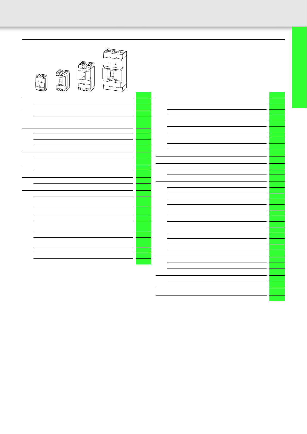
Content
1
System overview
Circuit-breakers, disconnect switches 2
Overview
Circuit-breakers,
Disconnect switches for North America, 3 pole
Circuit-breakers for North America
Thermomagnetic release, 3 pole 6
Magnetic 3 pole short-circuit release
Electronic release, 3 pole
Molded case switches for North America
3 pole 20
Disconnect switches for North America
3 pole 21
Engineering
Auxiliary contacts, trip indicating auxiliary contacts 22
Circuit-breakers, disconnect switches
Auxiliary contacts
with screw terminal
Undervoltage releases
with screw terminal
Undervoltage release, off-delayed
Shunt release
with screw terminal
Door coupling rotary handles
Rotary handles with door interlock for UL/CSA
approved NA switches
Rotary handles
Rotary handles with door interlock
Main switch assembly kit
Page
4
10
14
24
26
37
38
50
52
54
55
56
Page
Circuit-breakers, disconnect switches
Accessories 59
Mechanical interlock
Remote operators
Plug-in units
NZM1 terminals
NZM2 terminals
NZM3 terminals
NZM4 terminals
Accessories
Insulated terminals 90
Tripping characteristics
Tripping characteristics for circuit-breakers 91
Let-through characteristics for circuit-breakers
Technical data
Circuit-breakers 102
Disconnect switches
Molded Case Switches
Effective power loss
Terminal capacities
Remote operator, capacitor unit, auxiliary contact
Fitted with auxiliary contacts, timer differences
Undervoltage release, shunt release
Remote operator, capacitor unit
Data Management Interface (DMI Module)
Fieldbus connection
Direction of blow-out, minimum clearances, pipe cable lugs
Engineering
Mechanical interlock 122
Mechanical interlock for remote operator
Dimensions
Circuit-breakers, disconnect switches 125
Part number list 173
Alphabetical index 174
61
62
64
66
70
74
80
88
95
107
108
110
112
114
115
116
117
118
119
121
123
Circuit-breakers, disconnect switches
up to 1200 A
Page 3
2System overview
Circuit-breakers, disconnect switches
Moeller SK1230-1157EN-NA
Circuit-breakers, disconnect switches
up to 1200 A
4
3
26
2
25
1
22
24
23
5
5
6
7
8
9
11
21
20
19
16
17
18
14
13
12
10
15
Page 4
Moeller SK1230-1157EN-NA
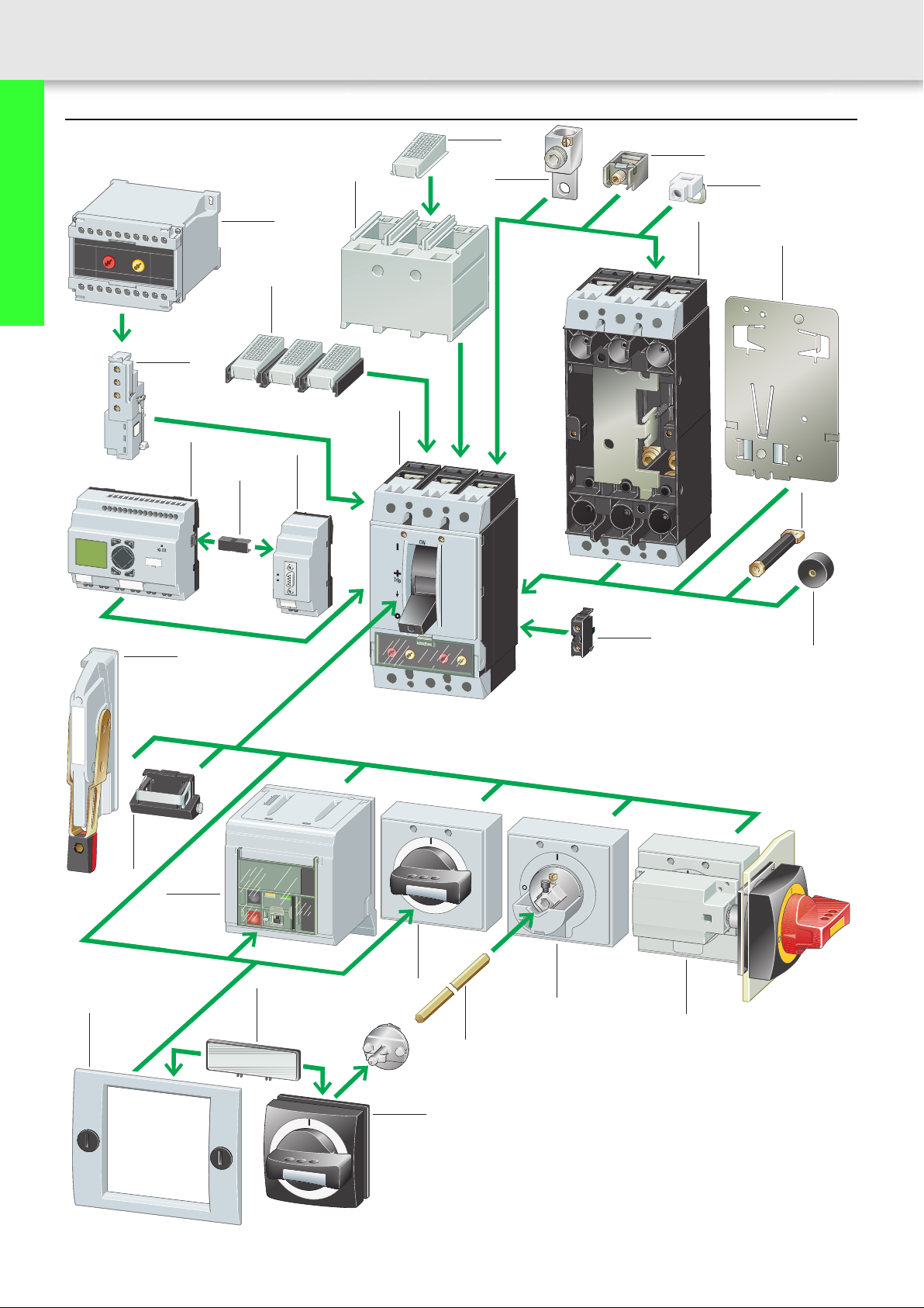
System overview
Circuit-breakers, disconnect switches
3
a 24
Circuit-breakers for North America 1
Rated uninterrupted current up to 1200 A
Switching capacity 25, 35, 42, 85,100 kA
at 480 V
Adjustable releases for overload and
short-circuit
Adjustable time selectivity
Earth-fault protection
Protection of systems, cables, motors,
generators
3 pole version,
UL489/CSA5, IEC 60947
a 6
Circuit-breakers without overcurrent
protection for North America
Rated uninterrupted current up to 1200 A
Remotely tripped, with undervoltage or
shunt release
3 pole version, UL489/CSA5
a 20
Disconnect switches for
North America
Rated uninterrupted current up to 1200 A
Remotely tripped disconnect switches with
undervoltage or shunt release
3 pole version, UL489/CSA5, IEC 60947
a 21
Add-on functions
Standard auxiliary contact 11
Switching with the main contacts
Used for indication and interlocking tasks
Trip-indicating auxiliary contact 11
General indication of tripping with trip
due to overload or short-circuit as well as
voltage release
Early-make auxiliary contacts 25
For interlocking and load shedding circuits,
as well as for early make of the
undervoltage release in main switch/
Emergency-stop applications
a 24
Voltage releases 25
1
1
Undervoltage release
• Non-delayed
• OFF-delayed
Shunt release
a 26
Spacers 10
a 60
Delay unit for undervoltage releases 26
a 50
Door coupling rotary handle 13, 15
•Lockable
• With door interlock
a 50
Main switch rotary handle for side
panel mounting
a 56
Extension shaft 14
Can be cut to required length.
a 50
Rotary handle 16
Lockable
a 54
Remote operator 19
For ON and OFF switching and resetting
by means of 2-wire or 3-wire control.
a 62
Toggle lever interlock device 20
a 60
Flange Operator 21
In preparation
Data Management Interface (DMI
Module)
Access to diagnostics and operational data
Recording of current values
Parameterization and control of the circuit-
breakers with electronic releases
a 88
EASY-LINK-DS data plug 23
a see main Moeller catalogue for
industrial switchgear
PROFIBUS-DP interface 24
a 88
12
22
Mounting accessories
Control circuit terminal 6
For two terminals at top or bottom
NZM1 a 68
NZM2 a 72
NZM3 a 76
NZM4 a 86
Tunnel terminals for Al and Cu cable 5
Standard with control circuit terminal
NZM1 a 66
NZM2 a 70
NZM3 a 76
NZM4 a 82
Box terminals 5
Standard equipment of frame size 1
Fitted within the switch housing
NZM1 a 66
NZM2 a 70
NZM3 a 74
Terminal cover 3
Protection against direct contact where
cable lugs, busbars or tunnel terminals are
used.
NZM1 a 68
NZM2 a 72
NZM3 a 78
NZM4 a 86
Clip plates 8
NZM1-XC35 for 35 mm top-hat rail
NZM1-XC75 for 75 mm top-hat rail
a 60
Rear connection 9
NZM1 a 66
NZM2 a 70
NZM3 a 76
NZM4 a 82
Plug-in and withdrawable unit 7
a 92
Insulating surround 18
For use with toggle levers, rotary drives
and remote operators protruding from the
enclosure
NZM1 a 60
External warning plate/designation
label
NZM1 a 59
IP2X protection against contact with
afinger
e
For box t
NZM1 a 68
NZM2 a 72
NZM3 a 78
IP2X protection against contact with
afinger
For barrier
NZM1 a 68
NZM2 a 72
NZM3 a 78
rminals
Circuit-breakers, disconnect switches
up to 1200 A
17
2
4
Page 5
4
Circuit-breakers, disconnect switches
up to 1200 A
Overview Overview
Circuit-breakers, disconnect switches for North America, 3 pole Circuit-breakers, disconnect switches for North America, 3 pole
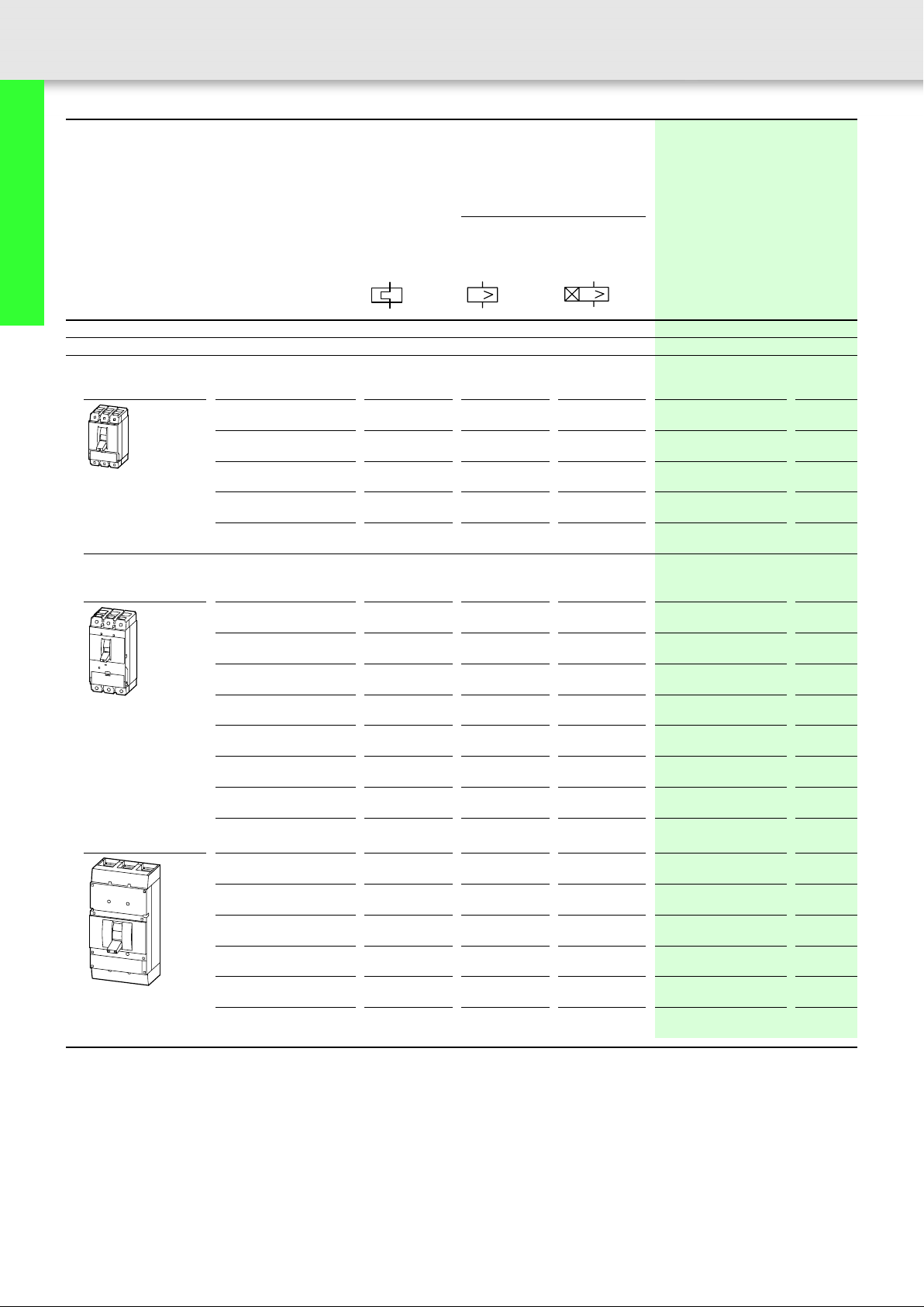
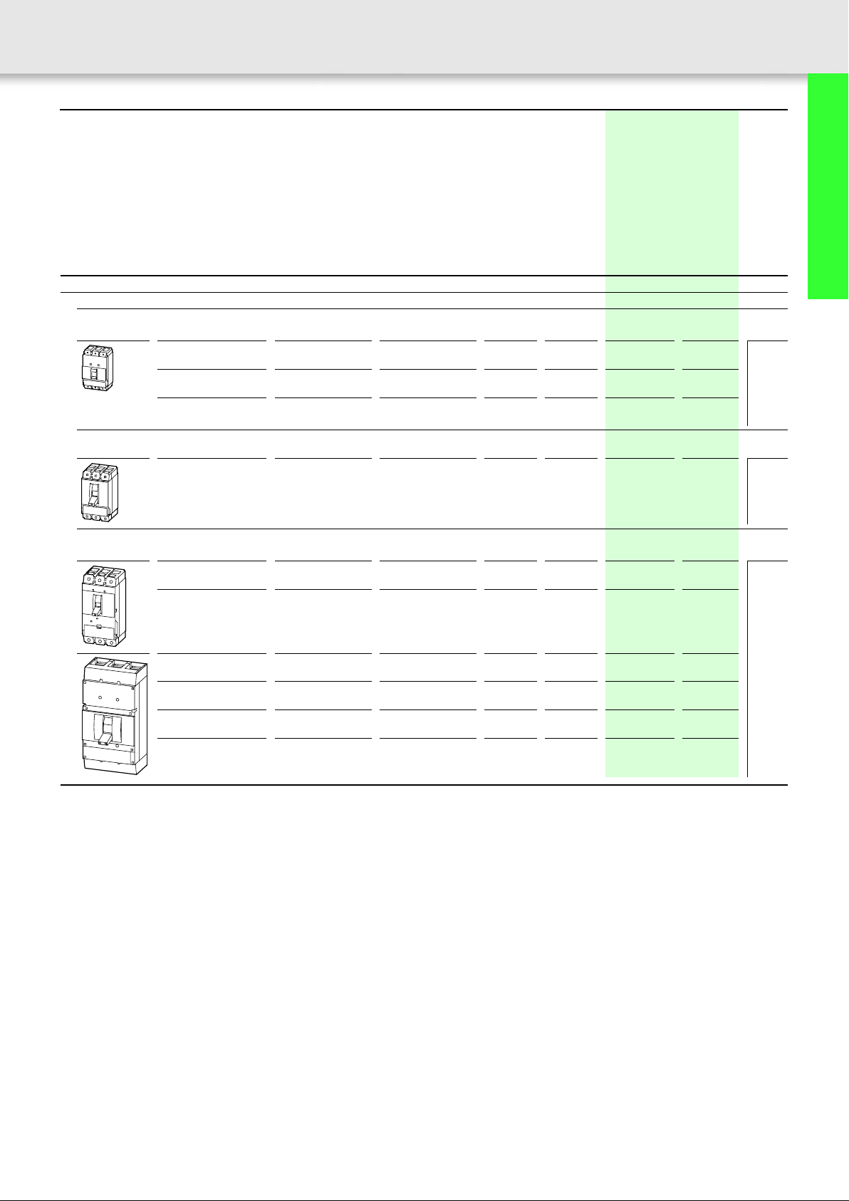
Circuit-breakers
UL/CSA approved to UL 489, CSA 22.2 No. 5.1 and
to IEC/EN 60947
With main switch characteristics to IEC/EN 60204 and isolating
characteristics to IEC/EN 60947, VDE 0660
Rated uninterrupted current
Adjustable overload releases
Adjustable short-circuit releases
Delayed short-circuit releases
Iu = Rated current
I
r
I
i
I
sd
I
n
Moeller SK1230-1157EN-NA
Thermomagnetic releases Electronic releases
Overload releases
Fixed Adjustable Without Fixed Adjustable Without Fixed Adjustable Without Fixed Adjustable System protection Motor
I
u
I
u
I
r
I
u
AAAA AAA AAAA AAAA A A A
NZM1 NZM2 NZM1 NZM2 NZM1 NZM2
15 –
125
15 –
250
20 –
125
20 –
250
1 x
I
n
1.2 –
100
1.6 –
250
Basic switching capacity
1)
NZMB1-...-NA NZMB2-...-NA
NEMA Test Procedure 240 V 60 Hz sym. rms kA 35 35
480 V 60 Hz sym. rms kA 25
2)
25
600 V 60 Hz sym. rms kA – 18
IEC/EN 60947 400/415 V kA/cos
440 V kA/cos
525 V kA/cos
Normal switching capacity
1)
v
v
v
25 0.25 25 0.25
25 0.25 25 0.25
15 0.30 15 0.30
NZMN1-...-NA NZMN2-...-NA NZMN2-...E...-NA NZMN3-...E...-NA NZMN4-...E...-NA
NEMA Test Procedure 240 V 60 Hz sym. rms kA 85 85 85 85 85
480 V 60 Hz sym. rms kA 35
2)
35 35 42 42
600 V 60 Hz sym. rms kA – 25 25 35 35
IEC/EN 60947 400/415 V kA/cos
440 V kA/cos
525 V kA/cos
690 V kA/cos
High switching capacity
1)
v
v
v
v
50 0.25 50 0.25 50 0.25 50 0.25 50 0.25
35 0.25 35 0.25 35 0.25 35 0.25 35 0.25
20 0.30 25 0.25 25 0.25 25 0.25 25 0.25
10 0.50 20 0.30 20 0.30 20 0.30 20 0.30
NZMH2-...-NA NZMH2-...E...-NA NZMH3-...E...-NA NZMH4-...E...-NA
NEMA Test Procedure 240 V 60 Hz sym. rms kA 150 150 150 125
480 V 60 Hz sym. rms kA 100 100 100 85
600 V 60 Hz sym. rms kA 50 50 50 50
IEC/EN 60947 400/415 V kA/cos
440 V kA/cos
525 V kA/cos
690 V kA/cos
Notes
1)
Breakers conform to UL/CSA as well as the IEC regulations
IEC switching performance values are contained on the rating plate.
2)
for NZM...1-...-NA > 50 A 480Y/277V
v
v
v
v
150 0.20 150 0.20 150 0.20 100 0.20
130 0.20 130 0.20 130 0.20 85 0.20
50 0.25 50 0.25 65 0.25 65 0.25
20 0.30 20 0.30 35 0.30 50 0.30
a
Technical data
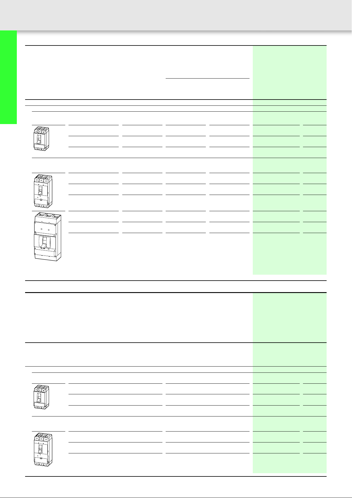
Disconnect switches:
UL/CSA approved to UL 489, CSA 22.2 No. 5.1 and to
IEC/EN 60947
With main switch characteristics to IEC/EN 60204 and VDE 0113
isolating characteristics to IEC/EN 60947-3 and VDE 0660.
without overload and short-circuit releases
Rated uninterrupted current I
Rated short-circuit making capacity
Rated short-time withstand current
= I
u
n
I
cm
Icw (1s current
kA 25 53 to UL 489, CSA 22.2 No. 5.1 240 V 85 150
)kA12 25 480 V 35 100
rms
400 600
550
800 63 160 400 800
1000
1200 125 250 1200
N3-...-NA N4-...-NA
Page 6
Moeller SK1230-1157EN-NA
5
Overload releases
I
150 –
250
I
u
u
100 –
250
I
r
0.5 – 1 x
I
u
In90 –
220
I
u
250 –
600
I
u
250 –
600
I
r
0.5 – 1 x
I
u
In220 –
450
I
u
600 –
1200
I
u
800 –
1200
I
r
0.5 – 1 x
Short-circuit releases
I
sd
In2 – 10 x
I
i
Ir2 – 12 x
protection
I
i
In2 – 14 x
Circuit-breakers, disconnect switches
up to 1200 A
I
n
The approved switches are suitable for world-wide use.
UL Certificates: file no.: E 31593 (NZM1-4), E 148671 (N(S)1-4)
CSA certificates: file no. 165628 (NZM1-4)
Molded case switch
UL/CSA approved to UL 489, CSA 22.2 No. 5.1 and
to IEC/EN 60947-2, Annex L
With main switch characteristics to IEC/EN 60204 and VDE 0113
Isolating characteristics to IEC/EN 60947
without overcurrent protection
Rated uninterrupted current I
Values printed in grey available on request
Switching capacity
IEC/EN 60947 400/415 V 50 150
u
= In
600 V – 50
440 V 35 130
525 V 20 50
690 10 20
100 200
NS1-...-NA NS2-...-NA
600
1000
Page 7
6
Circuit-breakers for North America Circuit-breakers for North America
Thermomagnetic releases, 3 pole Thermomagnetic releases, 3 pole
Moeller SK1230-1157EN-NA
Circuit-breakers, disconnect switches
up to 1200 A
Rated current = rated
uninterrupted current
In = I
u
AAA
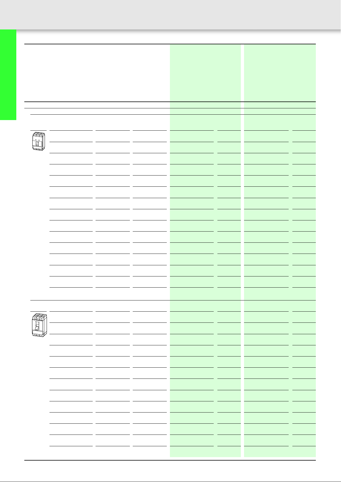
Protection of systems and cables
3-pole
Fixed overload releases
Terminals standard
terminal screw as accessories
15 15 350 NZMB1-AF15-NA
20 20 350
25 25 350 NZMB1-AF25-NA
30 30 350 NZMB1-AF30-NA
35 35 320 – 400 NZMB1-AF35-NA
40 40 320 – 400 NZMB1-AF40-NA
45 45 300 – 500 NZMB1-AF45-NA
50 50 300 – 500 NZMB1-AF50-NA
60 60 380 – 630 NZMB1-AF60-NA
70 70 480 – 800 NZMB1-AF70-NA
80 80 480 – 800 NZMB1-AF80-NA
90 90 600 – 1000 NZMB1-AF90-NA
100 100 600 – 1000 NZMB1-AF100-NA
110 110 750 – 1250 NZMB1-AF110-NA
125 125 750 – 1250 NZMB1-AF125-NA
Line and load Box Lugs installed
Setting range
Overload releases Short-circuit
I
r
releases
I
i
Basic switching capacity
35 kA 240 V
25 kA 480 V
18 kA 600 V
Part no.
Article no.
281553
NZMB1-AF20-NA
281554
281555
281556
272204
272205
272206
272207
272208
272209
272250
272251
272252
281557
281558
1)
2)
Price
see price
list
Normal switching capacity
85 kA 240 V
35 kA 480 V
25 kA 600 V
Part no.
Article no.
NZMN1-AF15-NA
281564
NZMN1-AF20-NA
281565
NZMN1-AF25-NA
281566
NZMN1-AF30-NA
281567
NZMN1-AF35-NA
274220
NZMN1-AF40-NA
274223
NZMN1-AF45-NA
274230
NZMN1-AF50-NA
274231
NZMN1-AF60-NA
274232
NZMN1-AF70-NA
274233
NZMN1-AF80-NA
274234
NZMN1-AF90-NA
274235
NZMN1-AF100-NA
274236
NZMN1-AF110-NA
281568
NZMN1-AF125-NA
281569
1)
2)
Price
see price
list
15 15 350 NZMB2-AF15-BT-NA
20 20 350
25 25 350 NZMB2-AF25-BT-NA
30 30 350 NZMB2-AF30-BT-NA
35 35 320 – 400 NZMB2-AF35-BT-NA
40 40 320 – 400 NZMB2-AF40-BT-NA
45 45 300 – 500 NZMB2-AF45-BT-NA
50 50 300 – 500 NZMB2-AF50-BT-NA
60 60 380 – 630 NZMB2-AF60-BT-NA
70 70 480 – 800 NZMB2-AF70-BT-NA
80 80 480 – 800 NZMB2-AF80-BT-NA
90 90 600 – 1000 NZMB2-AF90-BT-NA
100 100 600 – 1000 NZMB2-AF100-BT-NA
Notes Notes for terminals a 67
107611
NZMB2-AF20-BT-NA
107612
107613
107614
107615
107616
107617
107618
107619
107620
107621
107622
107623
NZMN2-AF15-BT-NA
107631
NZMN2-AF20-BT-NA
107632
NZMN2-AF25-BT-NA
107633
NZMN2-AF30-BT-NA
107634
NZMN2-AF35-BT-NA
107635
NZMN2-AF40-BT-NA
107636
NZMN2-AF45-BT-NA
107637
NZMN2-AF50-BT-NA
107638
NZMN2-AF60-BT-NA
107639
NZMN2-AF70-BT-NA
107640
NZMN2-AF80-BT-NA
107641
NZMN2-AF90-BT-NA
107642
NZMN2-AF100-BT-NA
107643
Page 8

Moeller SK1230-1157EN-NA
High switching capacity
100 kA 240 V
65 kA 480 V
35 kA 600 V
Part no.
Article no.
Price
see price
list
Std. pack Notes
7
Circuit-breakers, disconnect switches
up to 1200 A
1 off Switches conform to UL/CSA as well as the IEC regulations.
IEC switching performance values are contained on the rating plate.
UL 489, CSA-C22.2-5.1, IEC/EN 60947-2
Fixed overload releases I
Adjustable short-circuit release I
• Approx. 6 – 10 x In (ex-factory 6 x In)
– NZM...-AF35/40-NA: approx. 8 – 10 x I
Fixed short-circuit releases I
•350 A at In = 15 – 30A
1)
For basic switching capacity 25 kA 480 V and
r
i
n
i
normal switching capacity 35 kA 480 V the following applies:
for NZM...-1-...-NA: 480Y/277 V AC from 60 A.
NZMH2-AF15-BT-NA
107809
NZMH2-AF20-BT-NA
107810
NZMH2-AF25-BT-NA
107811
NZMH2-AF30-BT-NA
107812
NZMH2-AF35-BT-NA
107813
NZMH2-AF40-BT-NA
107814
NZMH2-AF45-BT-NA
107815
NZMH2-AF50-BT-NA
107816
NZMH2-AF60-BT-NA
107817
NZMH2-AF70-BT-NA
107818
NZMH2-AF80-BT-NA
107819
NZMH2-AF90-BT-NA
107820
NZMH2-AF100-BT-NA
107821
1 off Switches conform to UL/CSA as well as the IEC regulations.
IEC switching performance values are contained on the rating plate.
UL 489, CSA-C22.2-5.1, IEC/EN 60947-2
Fixed overload releases I
Adjustable short-circuit release I
• Approx. 6 – 10 x In (ex-factory 6 x In)
– NZM...-AF35/40-NA: approx. 8 – 10 x I
Fixed short-circuit releases I
•350 A at In = 15 – 30A
2)
For basic switching capacity 18 kA 600 V and normal switching capacity 25 kA 600 V the following applies: for
r
i
n
i
NZM2.
Page 9
8
Circuit-breakers for North America Circuit-breakers for North America
Thermomagnetic releases, 3 pole Thermomagnetic releases, 3 pole
Moeller SK1230-1157EN-NA
Circuit-breakers, disconnect switches
up to 1200 A
Rated current = rated
uninterrupted current
In = I
u
AAA
Protection of systems and cables
3-pole
Fixed overload release
Line and load Box Lugs installed
110 110 750 – 1250 NZMB2-AF110-BT-NA
125 125 750 – 1250
150 150 960 – 1600 NZMB2-AF150-BT-NA
175 175 1200 – 2000 NZMB2-AF175-BT-NA
200 200 1200 – 2000 NZMB2-AF200-BT-NA
225 225 1500 – 2500 NZMB2-AF225-BT-NA
250 250 1500 – 2500 NZMB2-AF250-BT-NA
Adjustable overload release
Line and load Box Lugs installed
Setting range
Overload releases Short-circuit
I
r
releases
I
i
Basic switching capacity
35 kA 240 V
25 kA 480 V
18 kA 600 V
Part no.
Article no.
107624
NZMB2-AF125-BT-NA
107625
107626
107627
107628
107629
107630
1)
2)
Price
see price
list
Normal switching capacity
85 kA 240 V
35 kA 480 V
25 kA 600 V
Part no.
Article no.
NZMN2-AF110-BT-NA
107644
NZMN2-AF125-BT-NA
107645
NZMN2-AF150-BT-NA
107646
NZMN2-AF175-BT-NA
107647
NZMN2-AF200-BT-NA
107648
NZMN2-AF225-BT-NA
107649
NZMN2-AF250-BT-NA
107650
1)
2)
Price
see price
list
20 15 – 20 350 NZMB1-A20-NA
25 20 – 25 350
32 25 – 32 350 NZMB1-A32-NA
40 32 – 40 320 – 400 NZMB1-A40-NA
50 40 – 50 300 – 500 NZMB1-A50-NA
63 50 – 63 380 – 630 NZMB1-A63-NA
80 63 – 80 480 – 800 NZMB1-A80-NA
100 80 – 100 600 – 1000 NZMB1-A100-NA
125 100 – 125 750 – 1250 NZMB1-A125-NA
Adjustable overload releases
Line and load Box Lugs installed
20 15 – 20 350 NZMB2-A20-BT-NA
25 20 – 25 350
32 25 – 32 350 NZMB2-A32-BT-NA
40 32 – 40 320 – 400 NZMB2-A40-BT-NA
50 40 – 50 300 – 500 NZMB2-A50-BT-NA
63 50 – 63 380 – 630 NZMB2-A63-BT-NA
80 63 – 80 480 – 800 NZMB2-A80-BT-NA
100 80 – 100 600 – 1000 NZMB2-A100-BT-NA
125 100 – 125 750 – 1250 NZMB2-A125-BT-NA
160 125 – 160 960 – 1600 NZMB2-A160-BT-NA
200 160 – 200 1200 – 2000 NZMB2-A200-BT-NA
250 200 – 250 1500 – 2500 NZMB2-A250-BT-NA
Notes Notes for terminals a 71
281559
NZMB1-A25-NA
281560
281561
272253
272254
272255
272256
272258
281562
107773
NZMB2-A25-BT-NA
107774
107775
107776
107777
107778
107779
107780
107781
107782
107783
107784
NZMN1-A20-NA
281570
NZMN1-A25-NA
281571
NZMN1-A32-NA
281572
NZMN1-A40-NA
274237
NZMN1-A50-NA
274239
NZMN1-A63-NA
274240
NZMN1-A80-NA
274241
NZMN1-A100-NA
274242
NZMN1-A125-NA
281573
NZMN2-A20-BT-NA
107785
NZMN2-A25-BT-NA
107786
NZMN2-A32-BT-NA
107787
NZMN2-A40-BT-NA
107788
NZMN2-A50-BT-NA
107789
NZMN2-A63-BT-NA
107790
NZMN2-A80-BT-NA
107791
NZMN2-A100-BT-NA
107792
NZMN2-A125-BT-NA
107793
NZMN2-A160-BT-NA
107794
NZMN2-A200-BT-NA
107795
NZMN2-A250-BT-NA
107796
Page 10

Moeller SK1230-1157EN-NA
High switching capacity
100 kA 240 V
65 kA 480 V
35 kA 600 V
Part no.
Article no.
Price
see price
list
Std. pack Notes
9
Circuit-breakers, disconnect switches
up to 1200 A
NZMH2-AF110-BT-NA
107822
NZMH2-AF125-BT-NA
107823
NZMH2-AF150-BT-NA
107824
NZMH2-AF175-BT-NA
107825
NZMH2-AF200-BT-NA
107826
NZMH2-AF225-BT-NA
107827
NZMH2-AF250-BT-NA
107828
1 off Switches conform to UL/CSA as well as the IEC regulations.
IEC switching performance values are contained on the rating plate.
UL 489, CSA-C22.2-5.1, IEC/EN 60947-2
Fixed overload releases I
Adjustable short-circuit release I
• Approx. 6 – 10 x In (ex-factory 6 x In)
– NZM...-AF35/40-NA: approx. 8 – 10 x I
Fixed short-circuit releases I
• 350 A at In = 15 – 30A
2)
For basic switching capacity 18 kA 600 V and normal switching capacity 25 kA 600 V the following applies:
r
i
n
i
for NZM2.
1 off Switches conform to UL/CSA as well as the IEC regulations.
IEC switching performance values are contained on the rating plate.
UL 489, CSA-C22.2-5.1, IEC/EN 60947-2
Adjustable overload release I
• 0.8 – 1 x In (ex-factory 0.8 x In)
Adjustable short-circuit release I
•6 – 10 x In (ex-factory 6 x In)
– NZM...-A40-NA: 8 – 10 x I
Fixed short-circuit releases I
• 350 A with In = 20 – 32 A
1)
For basic switching capacity 25 kA 480 V
r
i
n
i
and normal switching capacity 35 kA 480 V the following applies:
for NZM...-1-...-NA: 480Y/277 V AC from 60 A.
NZMH2-A20-BT-NA
107797
NZMH2-A25-BT-NA
107798
NZMH2-A32-BT-NA
107799
NZMH2-A40-BT-NA
107800
NZMH2-A50-BT-NA
107801
NZMH2-A63-BT-NA
107802
NZMH2-A80-BT-NA
107803
NZMH2-A100-BT-NA
107804
NZMH2-A125-BT-NA
107805
NZMH2-A160-BT-NA
107806
NZMH2-A200-BT-NA
107807
NZMH2-A250-BT-NA
107808
1 off Switches conform to UL/CSA as well as the IEC regulations.
IEC switching performance values are contained on the rating plate.
UL 489, CSA-C22.2-5.1, IEC/EN 60947-2
Adjustable overload release I
• 0.8 – 1 x In (ex-factory 0.8 x In)
Adjustable short-circuit release I
•6 – 10 x In (ex-factory 6 x In)
– NZM...-A40-NA: 8 – 10 x I
Fixed short-circuit releases I
• 350 A with In = 20 – 32 A
2)
For basic switching capacity 18 kA 600 V and normal switching capacity
r
i
n
i
25 kA 600 V the following applies: for NZM2.
Page 11
10
Circuit-breakers for North America Circuit-breakers for North America
Magnetic 3 pole short-circuit releases Magnetic 3 pole short-circuit releases
Moeller SK1230-1157EN-NA
Basic switching capacity
1)
480 V
Circuit-breakers, disconnect switches
up to 1200 A
Rated current = rated
uninterrupted current
In = I
u
AA
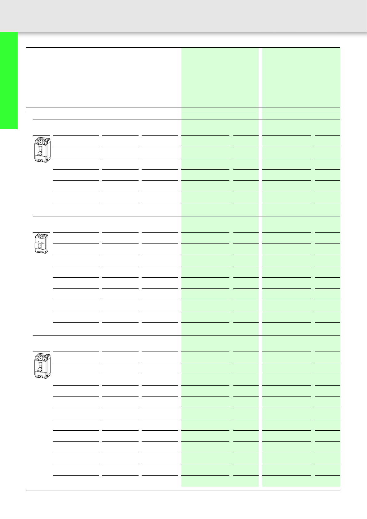
Short-circuit protection
Motor protection in conjunction with contactor and overload relay
• With short-circuit release
• Without overload release
3 pole
Terminals standard
terminal screw as accessories
1.2 8 – 14 NZMB1-S1,2-CNA
2 12.8 – 22.4
3 19.2 – 33.6 NZMB1-S3-CNA
532 – 56NZMB1-S5-CNA
848 – 84NZMB1-S8-CNA
12 80 – 140 NZMB1-S12-CNA
18 128 – 224 NZMB1-S18-CNA
26 200 – 350 NZMB1-S26-CNA
33 256 – 448 NZMB1-S33-CNA
40 320 – 560 NZMB1-S40-CNA
50 400 – 700 NZMB1-S50-CNA
63 504 – 882 NZMB1-S63-CNA
80 640 – 1120 NZMB1-S80-CNA
100 800 – 1250 NZMB1-S100-CNA
Notes Notes for terminals a 67
Setting range Part no.
Short-circuit releases
I
i
Article no.
I
102906
NZMB1-S2-CNA
102907
102908
102909
103020
103021
103022
103023
103024
281263
281264
281265
281266
281267
Price
see price
list
Std. pack Notes
1 off Switches conform to UL/CSA as well as the IEC regulations.
Page 12

Moeller SK1230-1157EN-NA
40 IEC switching performance values from 40 A are contained on the
rating plate.
UL 489, CSA-C22.2-5.1, IEC/EN 60947-4-1
Adjustable short-circuit release I
• 8 – 14 x In (ex-factory 12 x In)
– NZM...1-S1,2 – 33-CNA: approx. 8 – 14 x I
– NZM...1-S100-CNA: 8 – 12.5 x In (ex-factory 12 x In)
Without overload release I
i
n
r
11
Circuit-breakers, disconnect switches
up to 1200 A
CNA: The device has components approved to UL, the conditions of
approval must be observed during use.
i.e. the device must be combined with a suitable contactor and
overload relay.
A switching capacity is stated for the complete motor-starter
combination.
The device is approved as a CSA approved single device.
1)
480 Y/277 V AC from 60 A.
Page 13
12
Circuit-breakers for North America Circuit-breakers for North America
Magnetic 3 pole short-circuit releases Magnetic 3 pole short-circuit releases
Moeller SK1230-1157EN-NA
Basic switching capacity
480 V
600 V
Rated current = rated uninterrupted
current
In = I
u
AA
Setting range Part no.
Short-circuit releases
I
i
Article no.
I
Price
see price
list
Circuit-breakers, disconnect switches
up to 1200 A
Short-circuit protection
Motor protection in conjunction with contactor and overload relay
• With short-circuit release
• Without overload release
3 pole
Line and load Box Lugs installed
1.6 12.8 – 22.4 NZMB2-S1,6-BT-CNA
2.4 19.2 – 33.6
5 32 – 56 NZMB2-S5-BT-CNA
8 48 – 84 NZMB2-S8-BT-CNA
12 80 – 140 NZMB2-S12-BT-CNA
18 128 – 224 NZMB2-S18-BT-CNA
26 200 – 350 NZMB2-S26-BT-CNA
33 256 – 448 NZMB2-S33-BT-CNA
40 320 – 560 NZMB2-S40-BT-CNA
50 400 – 700 NZMB2-S50-BT-CNA
63 504 – 882 NZMB2-S63-BT-CNA
80 640 – 1120 NZMB2-S80-BT-CNA
100 800 – 1400 NZMB2-S100-BT-CNA
125 1000 – 1750 NZMB2-S125-BT-CNA
160 1280 – 2240 NZMB2-S160-BT-CNA
200 1600 – 2500 NZMB2-S200-BT-CNA
250 2000 – 2500 NZMB2-S250-BT-CNA
107651
NZMB2-S2,4-BT-CNA
107652
107653
107654
107655
107656
107657
107658
107659
107660
107661
107662
107663
107664
107665
107666
107667
Notes Notes for terminals a 71
Page 14
Moeller SK1230-1157EN-NA
Std. pack Notes
13
Circuit-breakers, disconnect switches
up to 1200 A
1 off Switches conform to UL/CSA as well as the IEC regulations.
40 IEC switching performance values from 40 A are contained on the
rating plate.
UL 489, CSA-C22.2-5.1, IEC/EN 60947-4-1
• NZM...2-S250-CNA: IEC/EN 60947-2
Adjustable short-circuit release I
• 8 – 14 x In (ex-factory 12 x In)
– NZM...2-S5 – 33-CNA: approx. 6 – 10 x I
– NZM...2-S250-CNA: 8 – 10 x I
Without overload release I
i
r
(ex-factory 10 x In)
(ex-factory 10 x In)
n
n
CNA: The device has components approved to UL, the conditions of
approval must be observed during use.
i.e. the device must be combined with a suitable contactor and overload
relay.
A switching capacity is stated for the complete motor-starter
combination.
The device is approved as a CSA approved single device.
Page 15
14
Circuit-breakers, disconnect switches
up to 1200 A
Circuit-breakers for North America Circuit-breakers for North America
Electronic releases, 3 pole Electronic releases, 3 pole
Rated current = rated
uninterrupted current
In = I
AAA
Protection of systems and cables
3 pole
Fixed overload releases
Terminal screws standard
terminals as accessories
250 250 500 – 2750 NZMN3-AEF250-NA
300 300 600 – 3300
350 350 700 – 3850 NZMN3-AEF350-NA
400 400 800 – 4400 NZMN3-AEF400-NA
450 450 900 – 3600 NZMN3-AEF450-NA
500 500 1000 – 4000 NZMN3-AEF500-NA
550 550 1100 – 4400 NZMN3-AEF550-NA
600 600 1200 – 4800 NZMN3-AEF600-NA
600 600 1200 – 7200 NZMN4-AEF600-NA
700 700 1400 – 8400 NZMN4-AEF700-NA
800 800 1600 – 9600 NZMN4-AEF800-NA
900 900 1800 – 10800 NZMN4-AEF900-NA
1000 1000 2000 – 12000 NZMN4-AEF1000-NA
1200 1200 2400 – 14400 NZMN4-AEF1200-NA
3 pole
Adjustable overload releases
Terminal screws standard
terminals as accessories
250 125 – 250 500 – 2750 NZMN3-AE250-NA
400 200 – 400 800 – 4400
600 300 – 600 1200 – 4800 NZMN3-AE600-NA
800 400 – 800 1600 – 9600 NZMN4-AE800-NA
1000 500 – 1000 2000 – 12000 NZMN4-AE1000-NA
1200 600 – 1200 2400 – 14400 NZMN4-AE1200-NA
Moeller SK1230-1157EN-NA
Normal switching capacity
85 kA 240 V
42 kA 480 V
35 kA 600 V
Setting range
Overload releases Short-circuit releases
Non-delayed
u
I
r
I
i
Part no.
Article no.
Price
see price
list
I
269275
NZMN3-AEF300-NA
269276
269277
269278
269279
269280
269281
269282
271108
271109
271110
271111
271112
271113
269299
NZMN3-AE400-NA
269300
269301
271120
271121
271122
Notes Notes for terminals a 71
Page 16

Moeller SK1230-1157EN-NA
High switching capacity
100 kA 240 V
65 kA 480 V
35 kA 600 V
Part no.
Article no.
Price
see price
list
Std. pack Notes
15
Circuit-breakers, disconnect switches
up to 1200 A
NZMH3-AEF250-NA
269283
NZMH3-AEF300-NA
269284
NZMH3-AEF350-NA
269285
NZMH3-AEF400-NA
269286
NZMH3-AEF450-NA
269287
NZMH3-AEF500-NA
269288
NZMH3-AEF550-NA
269289
NZMH3-AEF600-NA
269290
NZMH4-AEF600-NA
271114
NZMH4-AEF700-NA
271115
NZMH4-AEF800-NA
271116
NZMH4-AEF900-NA
271117
NZMH4-AEF1000-NA
271118
NZMH4-AEF1200-NA
271119
1 off Switches conform to UL/CSA as well as the IEC regulations.
IEC switching performance values are contained on the rating plate.
UL 489, CSA-C22.2-5.1, IEC/EN 60947-2
Fixed overload releases I
R.m.s. value measurement and “thermal memory”
Adjustable short-circuit release I
• With NZM...3-AEF250...400-NA: 2 – 11 x In (ex-factory 6 x In)
• With NZM...3-AEF450...600-NA: 2 – 8 x I
• With NZM...4-AEF...-NA: 2 – 12x I
1)
For limiter high switching capacity with NZMH4,
r
i
(ex-factory 6 x In)
n
(ex-factory 6 x In)
n
the following applies: 85 kA/480 V
NZMH3-AE250-NA
269302
NZMH3-AE400-NA
269303
NZMH3-AE600-NA
269304
NZMH4-AE800-NA
271123
NZMH4-AE1000-NA
271124
NZMH4-AE1200-NA
271125
1 off Switches conform to UL/CSA as well as the IEC regulations.
IEC switching performance values are contained on the rating plate.
UL 489, CSA-C22.2-5.1, IEC/EN 60947-2
Adjustable overload release I
• 0.5 – 1 x In (ex-factory 0.8 x In)
r
R.m.s. value measurement and “thermal memory”
Adjustable short-circuit release I
• With NZM...3-AE250/400-NA: 2 – 11 x In (ex-factory 6 x In)
• With NZM...3-AE600-NA: 2 – 8 x I
• With NZM...4-AE...-NA: 2 – 12 x I
1)
For limiter high switching capacity with NZMH4,
i
(ex-factory 6 x In)
n
(ex-factory 6 x In)
n
the following applies: 85 kA/480 V
Page 17
16
Circuit-breakers for North America Circuit-breakers for North America
Electronic releases, 3 pole Electronic releases, 3 pole
Moeller SK1230-1157EN-NA
Circuit-breakers, disconnect switches
up to 1200 A
Rated current = rated
uninterrupted current
In = I
u
A AAA
Systems, cable, transformer and generator protection
3 pole
Line and load terminals standard
Terminal screws standard
terminals as accessories
150 150 1800 300 – 1500 NZMN2-VEF150-BT-NA
175 175 2100 350 – 1750
200 200 2400 400 – 2000 NZMN2-VEF200-BT-NA
225 225 2700 450 – 2250 NZMN2-VEF225-BT-NA
250 250 3000 500 – 2500 NZMN2-VEF250-BT-NA
Terminal screws standard
terminals as accessories
Normal switching capacity
42 kA 480 V
35 kA 600 V
Setting range Part no.
Overload releases Short-circuit releases
Non-delayed Delayed
I
r
I
i
I
I
sd
I
Article no.
107593
NZMN2-VEF175-BT-NA
107594
107595
107596
107597
1)
2)
Price
see price
list
250 250 500 – 2750 500 – 2500 NZMN3-VEF250-NA
300 300 600 – 3300 600 – 3000 NZMN3-VEF300-NA
350 350 700 – 3850 700 – 3500 NZMN3-VEF350-NA
400 400 800 – 4400 800 – 4000 NZMN3-VEF400-NA
450 450 900 – 3600 675 – 3150 NZMN3-VEF450-NA
500 500 1000 – 4000 750 – 3500 NZMN3-VEF500-NA
550 550 1100 – 4400 825 – 3850 NZMN3-VEF550-NA
600 600 1200 – 4800 900 – 4200 NZMN3-VEF600-NA
600 600 1200 – 7200 1200 – 6000 NZMN4-VEF600-NA
700 700 1400 – 8400 1400 – 7000 NZMN4-VEF700-NA
800 800 1600 – 9600 1600 – 8000 NZMN4-VEF800-NA
900 900 1800 – 10800 1800 – 9000 NZMN4-VEF900-NA
1000 1000 2000 – 12000 2000 – 10000 NZMN4-VEF1000-NA
1200 1200 2400 – 14400 2400 – 12000 NZMN4-VEF1200-NA
Notes Notes for terminals a 71
269308
269309
269310
269311
269312
269313
269314
269315
271136
271137
271138
271139
271140
271141
Page 18

Moeller SK1230-1157EN-NA
High switching capacity
65 kA 480 V
35 kA 600 V
3)
Part no.
Article no.
Price
see price
list
Std. pack Notes
17
Circuit-breakers, disconnect switches
up to 1200 A
NZMH2-VEF150-BT-NA
107598
NZMH2-VEF175-BT-NA
107599
NZMH2-VEF200-BT-NA
107840
NZMH2-VEF225-BT-NA
107841
NZMH2-VEF250-BT-NA
107842
NZMH3-VEF250-NA
269316
NZMH3-VEF300-NA
269317
NZMH3-VEF350-NA
269318
NZMH3-VEF400-NA
269319
NZMH3-VEF450-NA
269320
NZMH3-VEF500-NA
269321
NZMH3-VEF550-NA
269322
NZMH3-VEF600-NA
269323
NZMH4-VEF600-NA
271142
NZMH4-VEF700-NA
271143
NZMH4-VEF800-NA
271144
NZMH4-VEF900-NA
271145
NZMH4-VEF1000-NA
271146
NZMH4-VEF1200-NA
271147
1 off Switches conform to UL/CSA as well as the IEC regulations.
IEC switching performance values are contained on the rating plate.
UL 489, CSA-C22.2-5.1, IEC/EN 60947-2
Fixed overload releases I
R.m.s. value measurement and 'thermal memory'
r
Adjustable time delay setting to overcome current peaks t
• 2 – 20 s with 6 x Ir (ex-factory 10 s)
Adjustable delayed short-circuit releases I
• 2 – 10 x Ir (ex-factory 6 x Ir)
– NZM...3-VEF450...600-NA: 1.5 – 7 x I
Adjustable delay time t
• Steps 0, 20, 60, 100, 200, 300, 500, 750, 1000 ms (ex-factory 0 ms)
sd
Adjustable non-delayed short-circuit releases I
• NZM2 fixed 12 x I
• NZM...3-VEF250...400-NA: 2 – 11 x In (ex-factory 11 x In)
n
• NZM...3-VEF450...600-NA: 2 – 8 x I
• NZM...4-VEF...-NA: 2 – 12 x I
2
t constant function
i
sd
(ex-factory 6 x Ir)
r
i
(ex-factory 8 x In)
n
(ex-factory 12 x In)
n
• NZM2 fixed OFF
• NZM3, NZM4 switched (ex-factory OFF)
1)
For normal switching capacity with NZMN2-...-NA,
the following applies: 35 kA/480 V
2)
For normal switching capacity with NZMN2-...-NA,
the following applies: 25 kA/600 V
3)
For limiter high switching capacity with NZMH4-...-NA,
the following applies: 85 kA/480 V
r
Page 19
18
Circuit-breakers for North America Circuit-breakers for North America
Electronic releases, 3 pole Electronic releases, 3 pole
Moeller SK1230-1157EN-NA
Circuit-breakers, disconnect switches
up to 1200 A
Rated current = rated
uninterrupted current
In = I
u
AAAA
Systems, cable, transformer and generator protection
3 pole
Adjustable overload release
Line and load Box Lugs installed
100 50 – 100 1200 100 – 1000 NZMN2-VE100-BT-NA
160 80 – 160 1920 160 – 1600 NZMN2-VE160-BT-NA
250 125 – 250 3000 250 – 2500 NZMN2-VE250-BT-NA
Terminal screws standard
terminals as accessories
250 125 – 250 500 – 2750 250 – 2500 NZMN3-VE250-NA
400 200 – 400 800 – 4400 400 – 4000 NZMN3-VE400-NA
600 300 – 600 1200 – 4800 450 – 4200 NZMN3-VE600-NA
800 400 – 800 1600 – 9600 800 – 8000 NZMN4-VE800-NA
1000 500 – 1000 2000 – 12000 1000 – 10000 NZMN4-VE1000-NA
1200 630 – 1200 2400 – 14400 1260 – 12000 NZMN4-VE1200-NA
Setting range Part no.
Overload releases Short-circuit releases
I
r
Non-delayed Delayed
I
i
I
sd
Normal switching capacity
42 kA 480 V
35 kA 600 V
Article no.
107843
107844
107845
269332
269333
269334
271154
271155
271156
1)
2)
Price
see price
list
Notes Notes for terminals a 71
Rated current = rated uninterrupted current Setting range Part no.
In = I
u
AA
Short-circuit protection
Motor protection in conjunction with contactor and overload relay
• With short-circuit release
• Without overload release
3 pole
Line and load Box Lugs installed
90 180 – 1260 NZMN2-SE90-BT-CNA
140 280 – 1960
220 440 – 3080 NZMN2-SE220-BT-CNA
Terminal screws standard
terminals as accessories
220 440 – 3080 NZMN3-SE220-CNA
350 700 – 4900 NZMN3-SE350-CNA
450 900 – 6300 NZMN3-SE450-CNA
Short-circuit releases
I
i
Normal switching capacity
480 V
600 V
Article no.
107849
NZMN2-SE140-BT-CNA
107850
107851
269341
269342
284465
Price
see price
list
Notes Notes for terminals a 71
Page 20
Moeller SK1230-1157EN-NA
High switching capacity
65 kA 480 V
35 kA 600 V
3)
Part no.
Article no.
NZMH2-VE100-BT-NA
107846
NZMH2-VE160-BT-NA
107847
NZMH2-VE250-BT-NA
107848
NZMH3-VE250-NA
269335
NZMH3-VE400-NA
269336
NZMH3-VE600-NA
269337
NZMH4-VE800-NA
271157
NZMH4-VE1000-NA
271158
NZMH4-VE1200-NA
271159
Price
see price
list
Std. pack Notes
1 off Switches conform to UL/CSA as well as the IEC regulations.
IEC switching performance values are contained on the rating plate.
UL 489, CSA-C22.2-5.1, IEC/EN 60947-2
Adjustable overload release I
• 0.5 – 1 x I
R.m.s. value measurement and “thermal memory”
n
r
Adjustable time delay setting to overcome current peaks t
• 2 – 20 s with 6 x Ir (ex-factory 10 s)
Adjustable delayed short-circuit releases I
• 2 – 10 x Ir (ex-factory 6 x Ir)
– NZM...3-VE600-NA: 1.5 – 7 x I
Adjustable delay time t
• Steps: 0, 20, 60, 100, 200, 300, 500, 750, 1000 ms (ex-factory 0 ms)
sd
Adjustable non-delayed short-circuit releases I
• NZM2 fixed 12 x I
• NZM...3-VE250/400-NA: 2 – 11 x In (ex-factory 11 x In)
n
• NZM...3-VE600-NA: 2 – 8 x I
• NZM...4-VE...-NA: 2 – 12 x I
2
t constant function
i
n
sd
(ex-factory 6 x Ir)
r
i
(ex-factory 8 x In)
n
(ex-factory 12 x In)
• NZM2 fixed OFF
• NZM3, NZM4 switched (ex-factory OFF)
1)
For normal switching capacity with NZMN2-...-NA: 35 kA/480 V
2)
For normal switching capacity with NZMN2-...-NA: 25 kA/600 V
3)
For limiter high switching capacity with NZMH4-...-NA: 85 kA/480 V
19
Circuit-breakers, disconnect switches
up to 1200 A
r
Std. pack Notes
1 off Switches conform to UL/CSA as well as the IEC regulations.
IEC switching performance values are contained on the rating plate.
UL 489, CSA-C22.2-5.1, IEC/EN 60947-2 and IEC/EN 60947-4
Adjustable short-circuit release I
• 2 – 14 x In (ex-factory 12 x In)
Without overload release I
i
r
CNA: The device has components approved to UL, the conditions of approval must be observed during use. i.e. the device must be combined with a suitable
contactor and overload relay. A switching capacity is stated for the complete motor-starter combination.
The device is approved as a CSA approved single device.
Page 21
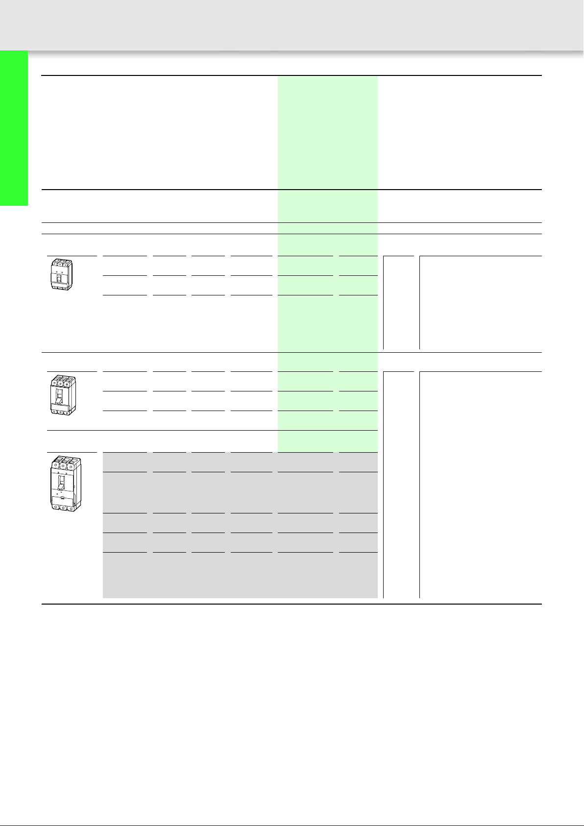
20 Molded case switches for North America
3 pole
3 switch positions I, + , 0 ;
can be tripped remotely with
shunt/under voltage release
Rated current
= rated
uninterrupted
current
Switching capacity Response
range of the
short-circuit
releases
Part no.
Article no.
Price
see price
list
Moeller SK1230-1157EN-NA
Std. pack Notes
Circuit-breakers, disconnect switches
up to 1200 A
In = I
u
AkAkAA
Molded case switches
These switches are recommended especially as incoming circuit-breakers for
the North American market.
3 pole
Terminals standard
terminal screw as accessories
63 35 – 1250 NS1-63-NA
100 35 – 1250
125 35 – 1250 NS1-125-NA
Line and load Box Lugs installed
160 100 50 2500 NS2-160-BT-NA
200 100 50 2500
250 100 50 2500 NS2-250-BT-NA
Terminal screws standard
terminals as accessories
400 100 50 4800 NS3-400-NA
600 100 50 4800 NS3-600-NA
At 480 V At 600 V I
i
102681
NS1-100-NA
102682
102683
107578
NS2-200-BT-NA
107579
107610
102687
102688
1 off Switches feature a fixed short-circuit
release (self-protection) and comply to
UL 489/CSA 22.2 No 5.1 regulations.
Furthermore the switches are tested to
IEC/EN 60947-2 as circuit-breakers
without overcurrent protection (CBI-X)
with main switch characteristics to
IEC/EN 60204 and isolating
characteristics to IEC 60947.
Notes
800 100 50 14400 NS4-800-NA
102689
1000 100 50 14400 NS4-1000-NA
102690
1200 100 50 14400 NS4-1200-NA
102691
Notes for terminals a 67
NS2, NS3 and NS4 can be combined with remote operator NZM...-XR...
Voltage releases U/A and trip-indicating auxiliary contacts can be used.
NS3 and NS4 currently under
development. Contact your Moeller
representative.
Page 22
Moeller SK1230-1157EN-NA
Disconnect switches for North America
3 pole
3 switch positions I, + , 0 ;
can be tripped remotely with
shunt/under voltage release
21
Rated current = rated
uninterrupted current
In = I
AAAkAkA
Switch-disconnector
3 pole
Terminals standard
terminal screws as accessories
63 125 150 10 – 1 off
100 125 150 10 –
125 125 150 10 –
Line and load Box Lugs installed
160 250 225 10 10 1 off
Terminal screws standard
terminals as accessories
400 630 –
550 630 –
Short-circuit
protection,
max. gG/gL fuse
Short-circuit
protection max. fuse
1)
OTS characteristic
Short-circuit rating with
OTS fuse
Part no.
Article no.
Price
see price
list
Std.
pack
At 480 V: At 600 V:
u
Circuit-breakers, disconnect switches
up to 1200 A
2)
14 14 N3-400-NA
1 off
271169
2)
14 14 N3-550-NA
293635
600 1600 –
800 1600 –
1000 1600 –
1200 1600 –
2)
2)
2)
2)
25 25 N4-600-NA
25 25 N4-800-NA
25 25 N4-1000-NA
25 25 N4-1200-NA
Notes Main switch characteristics including positive drive to IEC/EN 60204 and VDE 0113.
Isolating characteristics to IEC/EN 60947-3 and VDE 0660.
Protection against accidental contact according to IEC.
Undervoltage and shunt releases and HIA trip-indicating auxiliary contacts can be used in addition to N disconnect switches.
N3... and N4... can also be combined with the NZM...-XR... remote operator.
Switches conform to UL 489/CSA 22.2 No. 5.1 as well as to the IEC regulations.
Notes for terminals a 67
1)
for use when using a switch-disconnector to EN 60947-3.
2)
for use when using a switch-disconnector to N3...-NA and N4...-NA without protective device to UL 1087, CSA 22.2 No 5.2.
292386
271171
271172
271173
Page 23
22 Engineering
Auxiliary contacts, trip indicating auxiliary contacts
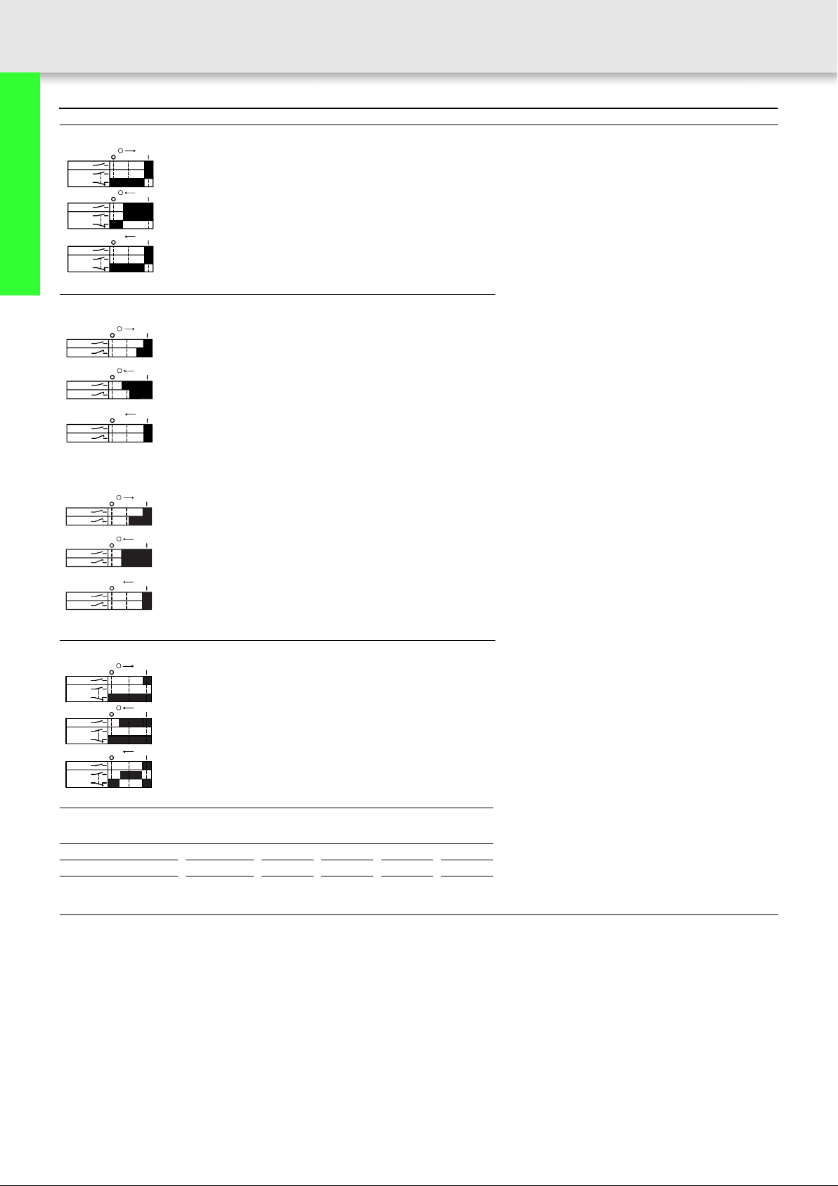
Contact sequence of the auxiliary contacts
Standard auxiliary contact (HIN)
I
+
I
+
I
+
+
I
+
I
+
I
+
+
Circuit-breakers, disconnect switches
up to 1200 A
L1L2L3
HIN
L1L2L3
HIN
L1L2L3
HIN
Early-make auxiliary contact (HIV)
NZM 1, 2, 3
L1L2L3
HIV
L1L2L3
HIV
L1L2L3
HIV
Moeller SK1230-1157EN-NA
0 l I Switch-on Q Contact closed
q Contact open
0 m I Switch-off
+ m I Trip
0 l I Switch-on Q Contact closed
q Contact open
0 m I Switch-off
+ m I Trip
NZM 4
L1L2L3
HIV
L1L2L3
HIV
L1L2L3
HIV
I
+
0 l I Switch-on Q Contact closed
I
+
+
I
+
0 m I Switch-off
q Contact open
+ m I Trip
Trip-indicating auxiliary contact (HIA)
I
L1L2L3
HIA
L1L2L3
HIA
L1L2L3
HIA
+
I
+
0 l I Switch-on Q Contact closed
q Contact open
0 m I Switch-off
I
+
+
+ m I Trip
Maximum component fitting NZM1 NZM2 NZM3 NZM4
HIN 1 N/O or 1 N/C 1 2 3 3
HIA 1 N/O or 1 N/C 1 1 1 2
HIV 2 N/O1111
Notes If early-make contacts are required in combination with shunt or undervoltage releases,
please select the combination type in the “Release” section.
Page 24

Moeller SK1230-1157EN-NA
Notes
23
Circuit-breakers, disconnect switches
up to 1200 A
Page 25
24
Circuit-breakers, disconnect switches
up to 1200 A
Circuit-breakers, disconnect switches Circuit-breakers, disconnect switches
Auxiliary contacts, with screw terminal Auxiliary contacts, with screw terminal
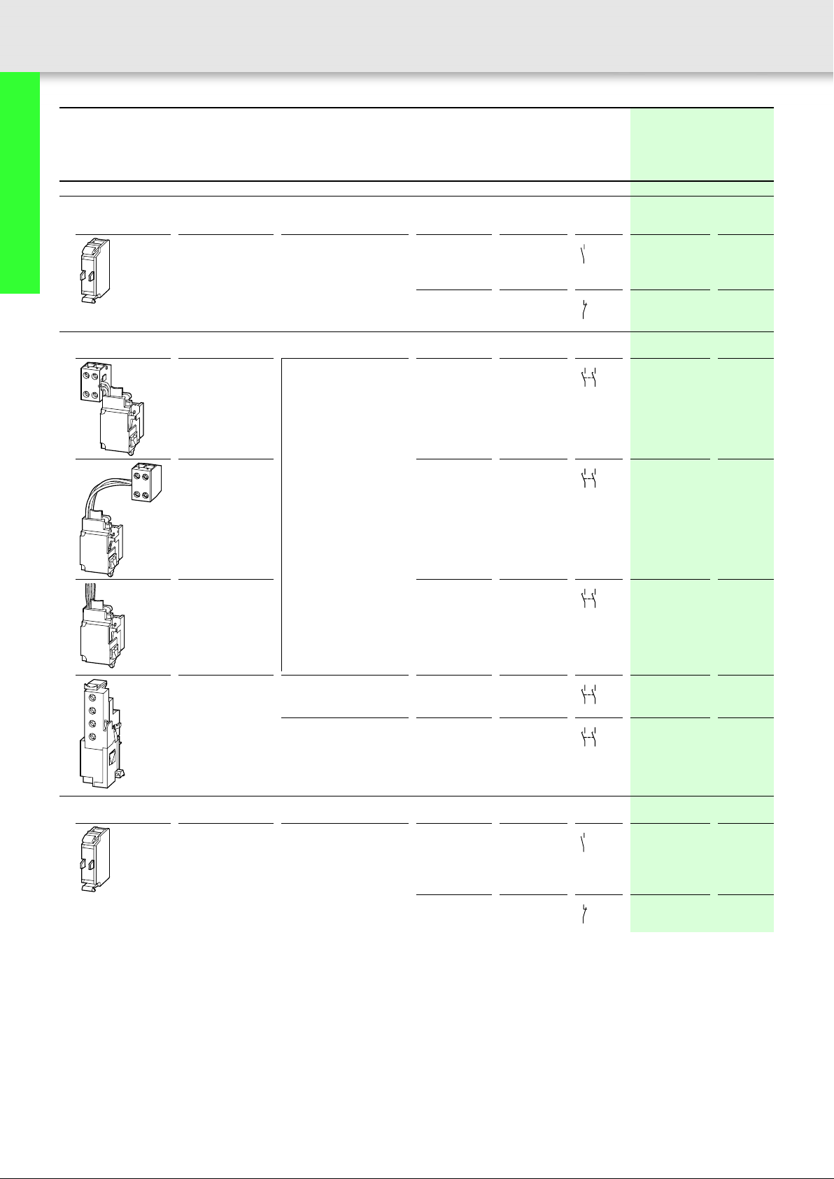
Auxiliary contacts
Standard auxiliary contact
Switching with the main contacts
Used for indicating and interlocking tasks
Early-make auxiliary contact
For interlock and load-shedding circuits
With clamp terminal
on the left-hand
switch side.
For use with Auxiliary contacts: f = safety
function, by positive opening to
IEC/EN 60947-5-1
NZM1, 2, 3, 4
N/O = Normally
open
1 N/O – M22-K10
N/C = Normally
closed
N1, 2, 3, 4
–1 N/C f
NZM1
2 N/O –
N1
Contact
sequence
1.X3
1.X4
1.X1
1.X2
3.13 3.23
3.14 3.24
Moeller SK1230-1157EN-NA
Part no.
Article no.
when ordered
Price
see price
list
separately
216376
M22-K01
216378
NZM1-XHIV
259426
With clamp terminal
2 N/O –
on the right-hand
switch side.
With 3 m connection
2 N/O –
cable instead of
screw termination.
NZM2, 3
2 N/O – NZM2/3-XHIV
N2, 3
NZM4
2 N/O – NZM4-XHIV
N4
Trip-indicating auxiliary contact (HIA)
General trip indication '+', when tripped by voltage release, overload release or short-circuit release
NZM1, 2, 3, 4
1 N/O – M22-K10
N1, 2, 3, 4
3.13 3.23
3.14 3.24
3.13 3.23
3.14 3.24
3.13 3.23
3.14 3.24
3.13 3.23
3.14 3.24
4.X3
4.X4
NZM1-XHIVR
292195
NZM1-XHIVL
259432
259430
266172
216376
–1 N/C f
4.X1
M22-K01
216378
4.X2
Page 26

Moeller SK1230-1157EN-NA
Notes
The following can be clipped into the switches:
• NZM1 – a standard auxiliary contact
• NZM2 up to two M22-K... standard auxiliary contacts
• NZM3 as well as NZM4 - up to 3 standard auxiliary
contacts M22-(C)K...
Any combinations of the auxiliary contact types is possible.
Marking on switch: HIN
Not in conjunction with undervoltage release NZM...XU(C)... or shunt release NZM...-XA(C)...
Early-make with on and off switching (manual operation):
approx. 20 ms
25
Circuit-breakers, disconnect switches
up to 1200 A
Not in conjunction with undervoltage release NZM...XU(C)..., shunt release NZM...-XA(C)... or remote operator
NZM...-XR...
Early-make with switch on (manual operation): approx.
90 ms
The following can be clipped into the switches:
• NZM1 - one trip-indicating auxiliary switch
• NZM2 - one M22-(C)K... trip-indicating auxiliary switch
• NZM3 - one M22-(C)K... trip-indicating auxiliary switch
• NZM4 - up to two M22-(C)K... trip-indicating auxiliary
switches
Any combinations of the auxiliary contact types ispossible.
Marking on switch: HIA
Page 27
26
Circuit-breakers, disconnect switches Circuit-breakers, disconnect switches
Undervoltage release Undervoltage release
Moeller SK1230-1157EN-NA
Circuit-breakers, disconnect switches
up to 1200 A
Undervoltage releases
Without auxiliary contact
Non-delayed disconnection of NZM circuit-breakers or N disconnect switches
when the control voltage sinks below 35 – 70% U
For use with Emergency-Stop devices in conjunction with Emergency-Stop button.
D1
U <
D2
.
S
With clamp terminal on the
left-hand switch side.
For use with Rated control voltage Part no.
U
s
V
NZM1, N1 24 V 50/60 Hz NZM1-XU24AC
110 V – 130 V 50/60 Hz
208 V 240 V 50/60 Hz NZM1-XU208-240AC
380 V – 440 V 50/60 Hz NZM1-XU380-440AC
480 V – 525 V 50/60 Hz NZM1-XU480-525AC
600 V 50/60 Hz NZM1-XU600AC
12 V DC NZM1-XU12DC
24 V DC NZM1-XU24DC
110 V – 130 V DC NZM1-XU110-130DC
220 V – 250 V DC NZM1-XU220-250DC
Article no.
when ordered separately
259434
NZM1-XU110-130AC
259440
259442
259444
259446
259448
259450
259452
259458
259460
Page 28

Moeller SK1230-1157EN-NA
Std. pack Notes
27
1 off When the undervoltage release is de-energized, accidental
contact with the main contacts of the switch during attempts to
switch on, is safely prevented .
Undervoltage release cannot be installed simultaneously with
NZM...-XHIV... early-make auxiliary contact or NZM...-XA...
shunt release.
Circuit-breakers, disconnect switches
up to 1200 A
Page 29
28
Circuit-breakers, disconnect switches Circuit-breakers, disconnect switches
Undervoltage release Undervoltage release
Moeller SK1230-1157EN-NA
Circuit-breakers, disconnect switches
up to 1200 A
Undervoltage releases
Without auxiliary contact
Non-delayed disconnection of NZM circuit-breakers or N disconnect switches
when the control voltage sinks below 35 – 70% U
For use with Emergency-Stop devices in conjunction with Emergency-Stop button.
D1
U <
D2
D1
U <
D2
.
S
–NZM2, N2
– NZM4, N4 24 V 50/60 Hz NZM4-XU24AC
For use with Rated control voltage Part no.
U
s
V
NZM3, N3
24 V 50/60 Hz NZM2/3-XU24AC
110 V – 130 V 50/60 Hz
208 V 240 V 50/60 Hz NZM2/3-XU208-240AC
380 V – 440 V 50/60 Hz NZM2/3-XU380-440AC
480 V – 525 V 50/60 Hz NZM2/3-XU480-525AC
600 V 50/60 Hz NZM2/3-XU600AC
12 V DC NZM2/3-XU12DC
24 V DC NZM2/3-XU24DC
110 V 130 V DC NZM2/3-XU110-130DC
220 V – 250 V DC NZM2/3-XU220-250DC
110 V – 130 V 50/60 Hz
208 V – 240 V 50/60 Hz NZM4-XU208-240AC
380 V – 440 V 50/60 Hz NZM4-XU380-440AC
480 V – 525 V 50/60 Hz NZM4-XU480-525AC
600 V 50/60 Hz NZM4-XU600AC
12 V DC NZM4-XU12DC
24 V DC NZM4-XU24DC
110 V – 130 V DC NZM4-XU110-130DC
220 V – 250 V DC NZM4-XU220-250DC
Article no.
when ordered separately
259491
NZM2/3-XU110-130AC
259497
259499
259501
259503
259505
259507
259509
259515
259517
266189
NZM4-XU110-130AC
266192
266193
266194
266195
266196
266203
266204
266207
266208
Page 30

Moeller SK1230-1157EN-NA
Std. pack Notes
29
1 off When the undervoltage release is de-energized, accidental
contact with the main contacts of the switch during attempts to
switch on, is safely prevented .
Undervoltage release cannot be installed simultaneously with
NZM...-XHIV... early-make auxiliary contact or NZM...-XA...
shunt release.
1 off
Circuit-breakers, disconnect switches
up to 1200 A
Page 31

30
Circuit-breakers, disconnect switches Circuit-breakers, disconnect switches
Undervoltage release Undervoltage release
Moeller SK1230-1157EN-NA
Circuit-breakers, disconnect switches
up to 1200 A
For use with Rated control voltage Part no.
Undervoltage releases
With two early-make auxiliary contacts
For interlocking and load-shedding circuits,
as well as for early-make of the undervoltage release in main-switch applications.
D1 3.13
3.14
D2
D1 3.13
3.14
D2
With clamp terminal on the
left-hand switch side.
With 3 m connection cable
instead of screw termination.
NZM1, N1 24 V 50/60 Hz NZM1-XUHIV24AC
NZM1, N1 24 V 50/60 Hz NZM1-XUHIVL24AC
Article no.
when ordered separately
U
s
V
259531
110 V – 130 V 50/60 Hz
208 V – 240 V 50/60 Hz NZM1-XUHIV208-240AC
380 V – 440 V 50/60 Hz NZM1-XUHIV380-440AC
480 V – 525 V 50/60 Hz NZM1-XUHIV480-525AC
12 V DC NZM1-XUHIV12DC
24 V DC NZM1-XUHIV24DC
110 V 130 V DC NZM1-XUHIV110-130DC
220 V – 250 V DC NZM1-XUHIV220-250DC
110 V – 130 V 50/60 Hz
208 V 240 V 50/60 Hz NZM1-XUHIVL208-240AC
380 V – 440 V 50/60 Hz NZM1-XUHIVL380-440AC
480 V – 525 V 50/60 Hz NZM1-XUHIVL480-525AC
12 V DC NZM1-XUHIVL12DC
24 V DC NZM1-XUHIVL24DC
110 V 130 V DC NZM1-XUHIVL110-130DC
220 V – 250 V DC NZM1-XUHIVL220-250DC
NZM1-XUHIV110-130AC
259537
259539
259541
259543
259545
259547
259553
259555
259557
NZM1-XUHIVL110-130AC
259563
259565
259567
259569
259571
259573
259579
259581
Page 32

Moeller SK1230-1157EN-NA
Std. pack Notes
31
1 off When the undervoltage release is de-energized, accidental
contact with the main contacts of the switch during attempts to
switch on is safely prevented.
Early-make of the auxiliary contacts with on and off switching
(manual operation): approx. 20 ms.
Undervoltage releases cannot be installed simultaneously with
NZM...-XHIV... early-make auxiliary contact or NZM...-XA...
shunt release.
Circuit-breakers, disconnect switches
up to 1200 A
Page 33

32
Circuit-breakers, disconnect switches Circuit-breakers, disconnect switches
Undervoltage release Undervoltage release
Moeller SK1230-1157EN-NA
Circuit-breakers, disconnect switches
up to 1200 A
For use with Rated control voltage Part no.
Undervoltage releases
With two early-make auxiliary contacts
For interlocking and load-shedding circuits,
as well as for early-make of the undervoltage release in main-switch applications.
D1 3.13
3.14
D2
D1 3.13
3.14
D2
NZM2, N2
NZM3, N3
NZM4, N4 24 V 50/60 Hz NZM4-XUHIV24AC
Article no.
when ordered separately
U
s
V
24 V 50/60 Hz NZM2/3-XUHIV24AC
110 V – 130 V 50/60 Hz
208 V – 240 V 50/60 Hz NZM2/3-XUHIV208-240AC
380 V – 440 V 50/60 Hz NZM2/3-XUHIV380-440AC
480 V – 525 V 50/60 Hz NZM2/3-XUHIV480-525AC
12 V DC NZM2/3-XUHIV12DC
24 V DC NZM2/3-XUHIV24DC
110 V 130 V DC NZM2/3-XUHIV110-130DC
220 V – 250 V DC NZM2/3-XUHIV220-250DC
110 V – 130 V 50/60 Hz
208 V – 240 V 50/60 Hz NZM4-XUHIV208-240AC
380 V – 440 V 50/60 Hz NZM4-XUHIV380-440AC
480 V – 525 V 50/60 Hz NZM4-XUHIV480-525AC
12 V DC NZM4-XUHIV12DC
24 V DC NZM4-XUHIV24DC
110 V – 130 V DC NZM4-XUHIV110-130DC
220 V – 250 V DC NZM4-XUHIV220-250DC
259583
NZM2/3-XUHIV110-130AC
259589
259591
259594
259598
259600
259602
259608
259610
266217
NZM4-XUHIV110-130AC
266220
266221
266222
266223
266231
266232
266235
266236
Page 34

Moeller SK1230-1157EN-NA
Std. pack Notes
33
1 off When the undervoltage release is de-energized, accidental
contact with the main contacts of the switch during attempts to
switch on is safely prevented.
Early-make of the auxiliary contacts with on and off switching
(manual operation): approx. 20 ms.
Cannot be used in conjunction with NZM...-XR... remote
operator.
Undervoltage releases cannot be installed simultaneously with
NZM...-XHIV... early-make auxiliary contact or NZM...-XA...
shunt release.
1 off When the undervoltage release is de-energized, accidental
contact with the main contacts of the switch during attempts to
switch on is safely prevented.
Early-make of the auxiliary contacts with switch on (manual
operation): approx. 90 ms.
Cannot be used in conjunction with NZM...-XR... remote
operator.
Undervoltage releases cannot be installed simultaneously with
NZM...-XHIV... early-make auxiliary contact or NZM...-XA...
shunt release.
Circuit-breakers, disconnect switches
up to 1200 A
Page 35

34 Circuit-breakers, disconnect switches
Undervoltage release
Moeller SK1230-1157EN-NA
Circuit-breakers, disconnect switches
up to 1200 A
For use with Rated control voltage Part no.
Undervoltage releases
With two separate early-make auxiliary contacts
With 3 m connection cable instead of screw termination.
D1
3.13
D2
3.14
NZM1, N1 24 V 50/60 Hz NZM1-XUHIV20L24AC
3.23
3.24
Contacts 3.23 and 3.24 with separate 3 m connection cables.
D1
3.13
D2
3.14
3.23
3.24
NZM2, N2
NZM3, N3
Article no.
U
s
when ordered separately
V
259612
110 V – 130 V 50/60 Hz
NZM1-XUHIV20L110-130AC
259620
208 V – 240 V 50/60 Hz NZM1-XUHIV20L208-240AC
259622
380 V – 440 V 50/60 Hz NZM1-XUHIV20L380-440AC
259624
480 V – 525 V 50/60 Hz NZM1-XUHIV20L480-525AC
259626
12 V DC NZM1-XUHIV20L12DC
259628
24 V DC NZM1-XUHIV20L24DC
259630
24 V 50/60 Hz NZM2/3-XUHIV2024AC
259640
110 V – 130 V 50/60 Hz
NZM2/3-XUHIV20110-130AC
259648
208 V – 240 V 50/60 Hz NZM2/3-XUHIV20208-240AC
259651
380 V – 440 V 50/60 Hz NZM2/3-XUHIV20380-440AC
259653
480 V – 525 V 50/60 Hz NZM2/3-XUHIV20480-525AC
259655
12 V DC NZM2/3-XUHIV2012DC
259657
24 V DC NZM2/3-XUHIV2024DC
259659
Price
see price
list
Std. pack
1 off
1 off
Notes When the undervoltage release is de-energized, accidental contact with the main contacts of the switch during attempts to switch on is safely
prevented.
Early-make of the auxiliary contacts with on and off switching (manual operation): approx. 20 ms.
Cannot be used in conjunction with NZM...-XR... remote operator.
Undervoltage releases cannot be installed simultaneously with NZM...-XHIV... early-make auxiliary contact or NZM...-XA... shunt release.
Page 36

Moeller SK1230-1157EN-NA
Circuit-breakers, disconnect switches
Undervoltage release
35
For use with Rated control voltage Part no.
Undervoltage releases
With two separate early-make auxiliary contacts
Coil connection wired to clamp terminal,
auxiliary switch connections wired with 3 m loose connection cables
D1
3.13
D2
3.14
NZM1, N1 24 V 50/60 Hz NZM1-XUHIV20KL24AC
3.23
3.24
Coil connection with 3 m loose connection cables,
auxiliary switch connections wired to clamp terminal
D1
3.13
D2
3.14
NZM1, N1 24 V 50/60 Hz NZM1-XUHIV20LK24AC
3.23
3.24
Coil connection with 3 m loose connection cables,
auxiliary switch connections wired to clamp terminal
D1
3.13
D2
3.14
3.23
3.24
NZM2, N2
NZM3, N3
Article no.
when ordered separately
U
s
V
284388
110 V – 130 V 50/60 Hz
NZM1-XUHIV20KL110-130AC
284389
208 V – 240 V 50/60 Hz NZM1-XUHIV20KL208-240AC
284400
24 V DC NZM1-XUHIV20KL24DC
284387
284402
110 V – 130 V 50/60 Hz
NZM1-XUHIV20LK110-130AC
284403
208 V – 240 V 50/60 Hz NZM1-XUHIV20LK208-240AC
284404
24 V DC NZM1-XUHIV20LK24DC
284401
24 V 50/60 Hz NZM2/3-XUHIV20LK24AC
285291
110 V – 130 V 50/60 Hz
NZM2/3-XUHIV20LK110-130AC
284407
208 V – 240 V 50/60 Hz NZM2/3-XUHIV20LK208-240AC
284408
24 V DC NZM2/3-XUHIV20LK24DC
284405
Price
see price
list
Std. pack
1 off
1 off
1 off
Circuit-breakers, disconnect switches
up to 1200 A
Notes When the undervoltage release is de-energized, accidental contact with the main contacts of the switch during attempts to turn on the switch
is safely prevented.
Early-make of the auxiliary contacts with on and off switching (manual operation): approx. 20 ms.
Cannot be used in conjunction with NZM...-XR... remote operator.
Undervoltage releases cannot be installed simultaneously with NZM...-XHIV... early-make auxiliary contact or NZM...-XA... shunt release.
Page 37

36 Circuit-breakers, disconnect switches
Undervoltage release
Moeller SK1230-1157EN-NA
Circuit-breakers, disconnect switches
up to 1200 A
For use with Rated control voltage Part no.
Article no.
when ordered separately
U
s
Price
see price
list
Std. pack
V
Undervoltage releases
With two separate early-make auxiliary contacts
Contacts 3.23 and 3.24 with separate 3 m connection cables.
D1
3.13
D2
3.14
NZM4, N4 24 V 50/60 Hz NZM4-XUHIV2024AC
3.23
3.24
110 V – 130 V 50/60 Hz
266244
NZM4-XUHIV20110-130AC
266247
1 off
208 V 240 V 50/60 Hz NZM4-XUHIV20208-240AC
266248
380 V – 440 V 50/60 Hz NZM4-XUHIV20380-440AC
266249
24 V DC NZM4-XUHIV2024DC
266258
Notes When the undervoltage release is de-energized, accidental contact with the main contacts of the switch during attempts to switch on is safely
prevented.
Early-make of the auxiliary contacts with switch on (manual operation): approx. 90 ms.
Cannot be used in conjunction with NZM...-XR... remote operator.
Undervoltage releases cannot be installed simultaneously with NZM...-XHIV... early-make auxiliary contact or NZM...-XA... shunt release.
Page 38

Moeller SK1230-1157EN-NA
Circuit-breakers, disconnect switches
Undervoltage release, off-delayed
37
For use with Part no.
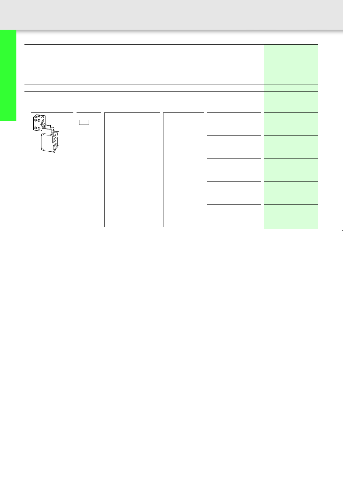
Undervoltage releases, off-delayed
Combination of separate delay unit and special tripping device.
Not UL/CSA approved
Delay unit
Voltage dips of less than the setting between 0.06 – 16 s
do not cause disconnection of the NZM circuit-breaker or
N switch-disconnector.
NZM1, 2, 3, 4
N1, 2, 3, 4
50/60 Hz
220 V – 240 V
380 V – 440 V
480 V – 550 V
DC/AC
24 V
Special tripping device
For combination with separate delay unit
Without auxiliary contacts
Article no.
when ordered
separately
UVU-NZM
260154
Price
see price
list
Std. pack Notes
1 off Adjustable delay time 70 ms – 4 s.
With additional capacitor up to 16 s.
A special tripping device is required.
Cannot be installed simultaneously with
NZM...-XHIV... or NZM...-XA... shunt release.
Delay unit for separate installation
(Fixing: top-hat rail or screws).
For other operating voltages use control
transformer.
Circuit-breakers, disconnect switches
up to 1200 A
NZM1 with 3 m separate connection cables instead of
screw terminal, NZM2, 3 , 4 with screw terminal
D1
U
D2
NZM1
N1
NZM2, N2
NZM3, N3
NZM4
N4
With 2 early-make auxiliary contacts
NZM1 with 3 m separate connection cables instead of
screw terminal, NZM2, 3 , 4 with screw terminal
D1 3.13
NZM1
N1
NZM2, N2
U
3.14D2
NZM3, N3
NZM4
N4
With 2 separately operating early-make auxiliary contacts
NZM1 with 3 m separate connection cables instead of screw
terminal, NZM2, 3, 4 with screw terminal, contact 3.23 and 3.24
with 3 m separate connection cables.
NZM1-XUVL
271607
NZM2/3-XUV
259527
NZM4-XUV
266588
NZM1-XUVHIVL
271608
NZM2/3-XUVHIV
259684
NZM4-XUVHIV
266596
1 off UVU-NZM delay unit is additionally required.
Cannot be installed simultaneously with
separate NZM...-XHIV early-make auxiliary
contact or NZM...-XA... shunt release.
1 off Cannot be used in conjunction with NZM...-XR...
remote operator.
UVU-NZM delay unit is additionally required.
Cannot be installed simultaneously with
separate NZM...-XHIV early-make auxiliary
contact or NZM...-XA... shunt release.
NZM1, 2, 3: Early-make of the auxiliary contacts
with on and off switching (manual operation):
approx. 20 ms.
NZM4: Early-make of the auxiliary contacts with
switch on (manual operation): approx. 90 ms.
D1
3.13
3.23
NZM1
N1
NZM2, N2
D2
3.14
3.24
NZM3, N3
NZM4
N4
NZM1-XUVHIV20L
271609
NZM2/3-XUVHIV20
259688
NZM4-XUVHIV20
266604
1 off Cannot be used in conjunction with NZM...-XR...
remote operator.
UVU-NZM delay unit is additionally required.
Cannot be installed simultaneously with
separate NZM...-XHIV early-make auxiliary
contact or NZM...-XA... shunt release.
NZM1, 2, 3: Early-make of the auxiliary contacts
with on and off switching (manual operation):
approx. 20 ms.
NZM4: Early-make of the auxiliary contacts with
switch on (manual operation): approx. 90 ms.
Page 39

38
Circuit-breakers, disconnect switches Circuit-breakers, disconnect switches
Shunt releases with screw terminal for NZM1 Shunt releases with screw terminal
Moeller SK1230-1157EN-NA
Circuit-breakers, disconnect switches
up to 1200 A
For use with Rated control voltage Part no.
Shunt releases
Without auxiliary contact
Switches are tripped by a voltage pulse or by the application of uninterrupted voltage.
With clamp terminal on the
C1
left-hand switch side.
C2
With 3 m connection cable
C1
instead of screw
termination.
C2
NZM1, N1 12 V AC/DC NZM1-XA12AC/DC
NZM1, N1 12 V AC/DC
Article no.
when ordered separately
U
s
V
259706
24 V AC/DC
110 V – 130 V AC/DC NZM1-XA110-130AC/DC
208 V – 250 V AC/DC NZM1-XA208-250AC/DC
380 V – 440 V AC/DC NZM1-XA380-440AC/DC
480 V – 525 V AC/DC NZM1-XA480-525AC/DC
24 V AC/DC
110 V – 130 V AC/DC NZM1-XAL110-130AC/DC
208 V – 250 V AC/DC NZM1-XAL208-250AC/DC
380 V – 440 V AC/DC NZM1-XAL380-440AC/DC
480 V – 525 V AC/DC NZM1-XAL480-525AC/DC
NZM1-XA24AC/DC
259708
259724
259726
259728
259730
NZM1-XAL12AC/DC
259734
NZM1-XAL24AC/DC
259736
259742
259744
259746
259748
Page 40

Moeller SK1230-1157EN-NA
Std. pack Notes
39
1 off When the undervoltage release is de-energized, accidental contact
with the main contacts of the switch during attempts to switch on,
is safely prevented.
Shunt release cannot be installed simultaneously with
NZM...-XHIV... early-make auxiliary contact or NZM...-XU...
undervoltage release.
1 off When the undervoltage release is de-energized, accidental contact
with the main contacts of the switch during attempts to switch on,
is safely prevented.
Shunt release cannot be installed simultaneously with
NZM...-XHIV... early-make auxiliary contact or NZM...-XU...
undervoltage release.
Circuit-breakers, disconnect switches
up to 1200 A
Page 41

40
Circuit-breakers, disconnect switches Circuit-breakers, disconnect switches
Shunt releases with screw terminal for NZM2, 3 and 4 Shunt releases with screw terminal
Moeller SK1230-1157EN-NA
Circuit-breakers, disconnect switches
up to 1200 A
For use with Rated control voltage Part no.
Shunt releases
Without auxiliary contact
Switches are tripped by a voltage pulse or by the application of uninterrupted voltage.
–NZM2, N2
C1
C2
– NZM4, N4 12 V AC/DC NZM4-XA12AC/DC
C1
C2
NZM3, N3
Article no.
when ordered separately
U
s
V
12 V AC/DC NZM2/3-XA12AC/DC
24 V AC/DC
110 V – 130 V AC/DC NZM2/3-XA110-130AC/DC
208 V – 250 V AC/DC NZM2/3-XA208-250AC/DC
380 V – 440 V AC/DC NZM2/3-XA380-440AC/DC
480 V – 525 V AC/DC NZM2/3-XA480-525AC/DC
24 V AC/DC
110 V – 130 V AC/DC NZM4-XA110-130AC/DC
208 V – 250 V AC/DC NZM4-XA208-250AC/DC
380 V – 440 V AC/DC NZM4-XA380-440AC/DC
480 V – 525 V AC/DC NZM4-XA480-525AC/DC
259752
NZM2/3-XA24AC/DC
259754
259760
259763
259766
259768
266446
NZM4-XA24AC/DC
266447
266450
266451
266452
266453
Page 42

Moeller SK1230-1157EN-NA
Std. pack Notes
41
1 off When the undervoltage release is de-energized, accidental contact
with the main contacts of the switch during attempts to switch on,
is safely prevented.
Shunt release cannot be installed simultaneously with
NZM...-XHIV... early-make auxiliary contact or NZM...-XU...
undervoltage release.
1 off When the undervoltage release is de-energized, accidental contact
with the main contacts of the switch during attempts to switch on,
is safely prevented.
Shunt release cannot be installed simultaneously with
NZM...-XHIV... early-make auxiliary contact or NZM...-XU...
undervoltage release.
Circuit-breakers, disconnect switches
up to 1200 A
Page 43

42
Circuit-breakers, disconnect switches Circuit-breakers, disconnect switches
Shunt releases with screw terminal Shunt releases with screw terminal
Moeller SK1230-1157EN-NA
Circuit-breakers, disconnect switches
up to 1200 A
Shunt releases
Without auxiliary contacts
For mesh-network circuit-breakers
For intermittent operation
Maximum on time = 1 s
Operating range 10 – 110 % U
not UL/CSA approved
s
C1
C2
C1
C2
For use with Rated control voltage Part no.
U
s
V
NZM3, N3 230 V AC NZM3-XA-230AC-MNS
NZM4, N4 230 V AC
Article no.
when ordered separately
274097
NZM4-XA-230AC-MNS
274138
Price
see price list
Std. pack Std. pack Notes
1 off 1 off Cannot be installed simultaneously with NZM...-XHIV... early-
1 off 1 off
Page 44

Moeller SK1230-1157EN-NA
make auxiliary contact or NZM...-XU... undervoltage release.
Intermittent operation guaranteed by series connection of an
M22-(C)K10 make contact.
The maximum operating time of the shunt release for mesh
network circuit-breaker is 1 s.
L1 (L+)
43
Circuit-breakers, disconnect switches
up to 1200 A
a
-S11
0
1.13
Q
HIN
-Q1
M22-...K10
1.14
C1
NZM...-XA...-MNS
C2
N (L-, L2)
a Reverse-power relay contact
-S11 Remote off
Q Standard auxiliary contact
-Q1 Shunt release
Page 45

44
Circuit-breakers, disconnect switches Circuit-breakers, disconnect switches
Shunt releases with screw terminal Shunt releases with screw terminal
Moeller SK1230-1157EN-NA
Circuit-breakers, disconnect switches
up to 1200 A
Shunt releases
With early-make auxiliary contact
C1
C2
C1
C2
With clamp terminal on the
3.13
left-hand switch side.
3.14
With 3 m connection cable
3.13
instead of screw termination.
3.14
For use with Rated control voltage Part no.
Article no.
when ordered separately
U
s
V
NZM1, N1 12 V AC/DC NZM1-XAHIV12AC/DC
259772
24 V AC/DC
NZM1-XAHIV24AC/DC
259774
110 V – 130 V AC/DC NZM1-XAHIV110-130AC/DC
259780
208 V – 250 V AC/DC NZM1-XAHIV208-250AC/DC
259782
380 V – 440 V AC/DC NZM1-XAHIV380-440AC/DC
259784
480 V – 525 V AC/DC NZM1-XAHIV480-525AC/DC
259786
NZM1, N1 12 V AC/DC NZM1-XAHIVL12AC/DC
259790
24 V AC/DC
NZM1-XAHIVL24AC/DC
259792
110 V – 130 V AC/DC NZM1-XAHIVL110-130AC/DC
259798
208 V – 250 V AC/DC NZM1-XAHIVL208-250AC/DC
259800
380 V – 440 V AC/DC NZM1-XAHIVL380-440AC/DC
259802
480 V – 525 V AC/DC NZM1-XAHIVL480-525AC/DC
259804
Page 46

Moeller SK1230-1157EN-NA
Std. pack Notes
45
1 off When the shunt release is energized, accidental contact with
the main contacts of the switch during attempts to switch on
is safely prevented.
Early-make of the auxiliary contact with on and off switching
(manual operation): approx. 20 ms.
Shunt release cannot be installed simultaneously with
NZM...-XHIV.. early-make auxiliary contact or NZM...-XU...
undervoltage release.
1 off
Circuit-breakers, disconnect switches
up to 1200 A
Page 47

46
Circuit-breakers, disconnect switches Circuit-breakers, disconnect switches
Shunt releases with screw terminal Shunt releases with screw terminal
Moeller SK1230-1157EN-NA
Circuit-breakers, disconnect switches
up to 1200 A
Shunt releases
With early-make auxiliary contact
C1
C2
C1
C2
For use with Rated control voltage Part no.
Article no.
when ordered separately
U
s
V
–NZM2, N2
3.13
NZM3, N3
3.14
12 V AC/DC NZM2/3-XAHIV12AC/DC
259808
24 V AC/DC
NZM2/3-XAHIV24AC/DC
259810
110 V – 130 V AC/DC NZM2/3-XAHIV110-130AC/DC
259816
208 V – 250 V AC/DC NZM2/3-XAHIV208-250AC/DC
259818
380 V – 440 V AC/DC NZM2/3-XAHIV380-440AC/DC
259820
480 V – 525 V AC/DC NZM2/3-XAHIV480-525AC/DC
259822
– NZM4, N4 12 V AC/DC NZM4-XAHIV12AC/DC
3.13
266470
3.14
24 V AC/DC
NZM4-XAHIV24AC/DC
266471
110 V – 130 V AC/DC NZM4-XAHIV110-130AC/DC
266474
208 V – 250 V AC/DC NZM4-XAHIV208-250AC/DC
266475
380 V – 440 V AC/DC NZM4-XAHIV380-440AC/DC
266476
480 V – 525 V AC/DC NZM4-XAHIV480-525AC/DC
266477
Page 48

Moeller SK1230-1157EN-NA
Std. pack Notes
47
1 off When the shunt release is energized, accidental contact with
the main contacts of the switch during attempts to switch on
is safely prevented.
Early-make of the auxiliary contact with on and off switching
(manual operation): approx. 20 ms.
Cannot be used in conjunction with NZM...-XR... remote
operator.
Shunt release cannot be installed simultaneously with
NZM...-XHIV.. early-make auxiliary contact or NZM...-XU...
undervoltage release.
1 off When the shunt release is energized, accidental contact with
the main contacts of the switch during attempts to switch on
is safely prevented.
Early-make of the auxiliary contact with switch on (manual
operation): approx. 90 ms.
Cannot be used in conjunction with NZM...-XR... remote
operator.
Shunt release cannot be installed simultaneously with
NZM...-XHIV.. early-make auxiliary contact or NZM...-XU...
undervoltage release.
Circuit-breakers, disconnect switches
up to 1200 A
Page 49

48
Circuit-breakers, disconnect switches Circuit-breakers, disconnect switches
Shunt releases with screw terminal Shunt releases with screw terminal
Moeller SK1230-1157EN-NA
Circuit-breakers, disconnect switches
up to 1200 A
Shunt releases
With early-make auxiliary contact
For mesh-network circuit-breakers
For intermittent operation
Maximum on time = 1 s
Operating range 10 – 110 % U
not UL/CSA approved
s
For use with Rated control voltage Part no.
Article no.
U
s
when ordered separately
V
3.13
C1
NZM3, N3 230 V AC NZM3-XAHIV-230AC-MNS
274141
C2
3.14
3.13
C1
NZM4, N4 230 V AC
NZM4-XAHIV-230AC-MNS
274143
C2
3.14
Page 50

Moeller SK1230-1157EN-NA
Std. pack Notes
1 off Cannot be installed simultaneously with NZM...-XHIV... early-
1 off
make auxiliary contact or NZM...-XU... undervoltage release.
Cannot be used in conjunction with NZM...-XR... remote
operator.
Intermittent operation guaranteed by series connection of a
N/O contact M22-(C)K10 (standard auxiliary contact).
The maximum operating time of the shunt release for mesh
network circuit-breaker is 1 s.
NZM3: Early-make of the auxiliary contact with on and off
switching (manual operation): approx. 20 ms.
NZM4: Early-make of the auxiliary contact with switch on
(manual operation): approx. 90 ms.
49
Circuit-breakers, disconnect switches
up to 1200 A
Page 51

50
Circuit-breakers, disconnect switches Circuit-breakers, disconnect switches
Door coupling rotary handles Door coupling rotary handles
Moeller SK1230-1157EN-NA
Circuit-breakers, disconnect switches
up to 1200 A
For use with
CSA only
Door coupling rotary handle
Complete including rotary drive and coupling parts
An additional extension shaft is necessary with the NZM...-XT(V)D(V)(R)(-60) types.
Degree of protection IP66/UL/CSA Type 4X
Standard, black/grey
Lockable in 0 position on
handle. With door
interlock
Lockable on handle and
switch. Can be locked in
0 position, with adequate
modification also in
I position. With door
interlock Lockable in
0 position on circuitbreaker.
Red-yellow for Emergency-Stop
Lockable on handle and
switch. Lockable in
0 position on handle. With
door interlock Lockable in
0 position on circuitbreaker.
NZM1, N1
NZM2, N2
NZM3, N3 NZM3-XTVD
NZM4, N4 NZM4-XTVD
NZM1, N1
NZM2, N2 NZM2-XTVDV
NZM3, N3 NZM3-XTVDV
NZM4, N4 NZM4-XTVDV
NZM1, N1
NZM2, N2
NZM3, N3 NZM3-XTVDVR
NZM4, N4 NZM4-XTVDVR
Part no.
Article no.
when ordered
separately
NZM1-XTVD
260166
NZM2-XTVD
260168
260170
266614
NZM1-XTVDV
260172
260174
260176
266616
NZM1-XTVDVR
260178
NZM2-XTVDVR
260180
260182
266618
Price
see price
list
Std. pack Notes
Door interlock
• Not defeated in the locked
OFF and ON positions
• Can be modified such that it
can be defeated from the
outside using a screwdriver,
when it is in the unlocked
ON position.
• Door can be opened in OFF
NZM...-XTVD(V)
•External warning plate/
designation label can be
clipped on
1 off Door interlock
• Not defeatable in the
locked OFF position.
• Can be modified such that it
can be defeated from the
outside using a screwdriver,
when it is in the unlocked
ON position.
• Door can be opened in OFF
NZM...-XTVDVR
•External warning plate/
designation label can be
clipped on
Extension shaft
Max. mounting depth:
400 mm
Max. mounting depth:
600 mm
Notes Circuit-breaker can also be installed in a lying position 90° left/right, with the handle still in the same position.
NZM1, N1
NZM2, N2
NZM3, N3
NZM4, N4
NZM1, N1
NZM2, N2
NZM3, N3
NZM4, N4
NZM1/2-XV4
261232
NZM3/4-XV4
261234
NZM1/2-XV6
260191
NZM3/4-XV6
260193
1 off Can be cut to required length
Page 52

Moeller SK1230-1157EN-NA
For a max. shaft length of 60 mm Extremely narrow fittings
Part no.
Article no.
when ordered
separately
NZM1-XTVDV-60
271508
NZM2-XTVDV-60
271509
NZM3-XTVDV-60
271510
NZM4-XTVDV-60
271511
Price
see price
list
Std. pack Notes
Door interlock
• For maximum shaft length 60
mm
• Without shaft support
• Cannot be combined with
NZM...-XDZ additional handle
• External warning plate/
designation label can be
clipped on
Part no.
Article no.
when ordered
separately
NZM1-XTVDV-0
279396
NZM2-XTVDV-0
279397
NZM3-XTVDV-0
279398
NZM4-XTVDV-0
279399
Price
see price
list
Std. pack Notes
Door interlock
• Not defeated in the locked OFF
and ON positions
• Can be modified such that it can
be defeated from the outside
using a screwdriver, when it is in
the unlocked ON position.
• Door can be opened in OFF
NZM...-XTVDV-0
• For extremely narrow fittings
• With special short extension
shaft
• Cannot be combined with
NZM...-XDZ additional handle
• External warning plate/
designation label can be clipped
on
51
Circuit-breakers, disconnect switches
up to 1200 A
NZM1-XTVDVR-60
271512
NZM2-XTVDVR-60
271513
NZM3-XTVDVR-60
271514
NZM4-XTVDVR-60
271515
1 off Door interlock
• Not defeatable in the locked
OFF position.
• Can be modified such that it
can be defeated from the
outside using a screwdriver,
when it is in the unlocked ON
position.
• Door can be opened in OFF
NZM...-XTVDVR-60
• For maximum shaft length 60
mm
• Without shaft support
• Cannot be combined with
NZM...-XDZ additional handle
• External warning plate/
designation label can be
clipped on
NZM1-XTVDVR-0
279400
NZM2-XTVDVR-0
279401
NZM3-XTVDVR-0
279402
NZM4-XTVDVR-0
279403
1 off Door interlock
• Not defeatable in the locked OFF
position.
• Can be modified such that it can
be defeated from the outside
using a screwdriver, when it is in
the unlocked ON position.
• Door can be opened in OFF
NZM...-XTVDVR-0
• For extremely narrow fittings
• With special short extension
shaft
• Cannot be combined with
NZM...-XDZ additional handle
• External warning plate/
designation label can be clipped
on
Page 53

52
Circuit-breakers, disconnect switches
up to 1200 A
Circuit-breakers, disconnect switches Circuit-breakers, disconnect switches
Rotary handles with door interlock for UL/CSA approved NA switches Rotary handles with door interlock for UL/CSA approved NA switches
Door coupling rotary handle
Complete including rotary drive and coupling parts
Extension shaft additionally required.
Degree of protection IP66/UL/CSA Type 4X
Standard, black/grey
Lockable on handle and
switch. Can be locked in
0 position, with adequate
modification also in
I position. With door
interlock Lockable in
0 position on breaker.
Standard For a max. shaft length of 60 mm Extremely narrow fittings
For use with
NZM1, N1
NZM2, N2
NZM3, N3 NZM3-XTVDV-NA
NZM4, N4 NZM4-XTVDV-NA
Part no.
Article no.
when ordered
separately
NZM1-XTVDV-NA
100683
NZM2-XTVDV-NA
100684
100685
100686
Price
see price
list
Moeller SK1230-1157EN-NA
Std. pack Notes
1 off Door interlock
• Not defeated in the locked
OFF position
• Door opening possible with
active rotation beyond the
0 position.
• Cannot be combined with
mechanical interlock
•External warning plate/
designation label can be
clipped on
Red-yellow for Emergency-Stop
Extension shaft
Lockable on handle and
switch. Lockable in
0 position on handle. With
door interlock Lockable in
0 position on breaker.
Max. mounting depth:
400 mm
Max. mounting depth:
600 mm
NZM1, N1
NZM2, N2
NZM3, N3 NZM3-XTVDVR-NA
NZM4, N4 NZM4-XTVDVR-NA
NZM1,
N1
NZM2,
N2
NZM3,
N3
NZM4, N4
NZM1,
N1
NZM2,
PN2, N2
NZM3,
N3
NZM4, N4
NZM1-XTVDVR-NA
271449
NZM2-XTVDVR-NA
271450
271451
271452
NZM1/2-XV4
261232
NZM3/4-XV4
261234
NZM1/2-XV6
260191
NZM3/4-XV6
260193
1 off Door interlock
• Not defeated in the locked
OFF position
• Door opening possible with
active rotation beyond the
0 position.
• Cannot be combinedwith
mechanical interlock
•External warning plate/
designation label can be
clipped on
1 off Can be cut to required length
Notes Circuit-breaker can also be installed in a lying position 90° left/right, with the handle still in the same position.
Page 54

Moeller SK1230-1157EN-NA
53
Part no.
Article no.
when ordered
separately
NZM1-XTVDV-60-NA
100667
NZM2-XTVDV-60-NA
100668
NZM3-XTVDV-60-NA
100669
NZM4-XTVDV-60-NA
100670
NZM1-XTVDVR-60-NA
100671
NZM2-XTVDVR-60-NA
100672
NZM3-XTVDVR-60-NA
100673
NZM4-XTVDVR-60-NA
100674
Price
see price
list
Notes
Door interlock
• Not defeated in the locked OFF
position
• Door opening possible with active
rotation beyond the 0 position.
• Cannot be combined with
mechanical interlock
• External warning plate/
designation label can be clipped
on
NZM...-XTVDV-60-NA
• For a maximum shaft length of
60 mm
• Without shaft support
• Cannot be combined with
NZM...-XDZ additional handle
• External warning plate/
designation label can be clipped
on
Door interlock
• Not defeated in the locked OFF
position
• Door opening possible with active
rotation beyond the 0 position.
• Cannot be combined with
mechanical interlock
• External warning plate/
designation label can be clipped
on
NZM...-XTVDVR-60-NA
• For a maximum shaft length of
60 mm
• Without shaft support
• Cannot be combined with
NZM...-XDZ additional handle
• External warning plate/
designation label can be clipped
on
Part no.
Article no.
when ordered
separately
NZM1-XTVDV-0-NA
100675
NZM2-XTVDV-0-NA
100676
NZM3-XTVDV-0-NA
100677
NZM4-XTVDV-0-NA
100678
NZM1-XTVDVR-0-NA
100679
NZM2-XTVDVR-0-NA
100680
NZM3-XTVDVR-0-NA
100681
NZM4-XTVDVR-0-NA
100682
Price
see price
list
Std. pack Notes
1 off Door interlock
• Not defeated in the locked OFF
position
• Door opening possible with active
rotation beyond the 0 position.
• Cannot be combined with
mechanical interlock
• External warning plate/
designation label can be clipped
on
NZM...-XTVDV-0-NA
• For extremely narrow fittings
• With special short extension shaft
• Cannot be combined with
NZM...-XDZ additional handle
• External warning plate/
designation label can be clipped
on
1 off Door interlock
• Not defeated in the locked OFF
position
• Door opening possible with active
rotation beyond the 0 position.
• Cannot be combined with
mechanical interlock
• External warning plate/
designation label can be clipped
on
NZM...-XTVDVR-0-NA
• For extremely narrow fittings
• With special short extension shaft
• Cannot be combined with
NZM...-XDZ additional handle
• External warning plate/
designation label can be clipped
on
Circuit-breakers, disconnect switches
up to 1200 A
Page 55

54 Circuit-breakers, disconnect switches
Rotary handles
Moeller SK1230-1157EN-NA
Circuit-breakers, disconnect switches
up to 1200 A
CSA only
Rotary handles
Complete with rotary drive
Standard, black/grey
Lockable on the 0 position
on the switch using up to
3 padlocks.
Lockable on the 0 position
on the handle using up to
3 padlocks.
Red-yellow for Emergency-Stop
Lockable on the 0 position
on the switch using up to
3 padlocks.
For use with Part no.
NZM1, N1
NZM2, N2
NZM3, N3 NZM3-XDV
NZM4, N4 NZM4-XDV
NZM1, N1
NZM2, N2
NZM1, N1
NZM2, N2
Article no.
when ordered
separately
NZM1-XDV
260125
NZM2-XDV
260127
260129
266608
NZM1-XDVG
285247
NZM2-XDVG
285248
NZM1-XDVR
260135
NZM2-XDVR
260137
Price
see price
list
Std. pack Notes
NZM1, 2, 3: Can also be combined
with insulating surround.
MODAN handle position detection by
wire release can be retrofitted.
Can also be combined with insulating
surround.
1 off NZM1, 2, 3: Can also be combined
with insulating surround.
MODAN handle position detection by
wire release can be retrofitted.
NZM3, N3 NZM3-XDVR
NZM4, N4 NZM4-XDVR
Lockable on the 0 position
on the handle using up to 3
padlocks.
Notes Circuit-breaker can also be installed in a lying position 90° left/right, with the handle still in the same position.
NZM1, N1
NZM2, N2
260140
266610
NZM1-XDVGR
285249
NZM2-XDVGR
285280
Can also be combined with insulating
surround.
Page 56

Moeller SK1230-1157EN-NA
Notes
55
Circuit-breakers, disconnect switches
up to 1200 A
Page 57

56 Circuit-breakers, disconnect switches
Main switch assembly kit
Moeller SK1230-1157EN-NA
Circuit-breakers, disconnect switches
up to 1200 A
For use with Part no.
CSA only
Main switch assembly kit
Equipment supplied:
• Rotary door-coupling handle
• NZM...-XV4 extension shaft
• External warning plate/designation label in German/English
• Black and yellow flash
For enhanced protection against direct contact on the incomer side, IP2X protection against contact with a finger can be
ordered a 68
Other external warning plates/designation labels can be clipped on.
With black door coupling rotary handle
With red door coupling rotary handle for using switch as Emergency-Stop device according to IEC/EN 602041
Main switch assembly kit for side panel mounting
Actuation of the switch on the control panel side wall
Switch mounting on mounting plate
Equipment supplied:
• Door coupling rotary handle
• NZM...-XV4 extension shaft
• External warning plate/designation label in German/English
• Black and yellow flash
For enhanced protection against direct contact on the incomer side, IP2X protection against contact with a finger can be
ordered a 68
Other external warning plates/designation labels can be clipped on.
Standard, black/grey
Red-yellow for Emergency-Stop
Lockable in 0 position on handle. With
door interlock
Lockable in 0 position on handle.
Lockable door, locking facility on
circuit-breaker in 0 position.
Can be locked in 0 position, with
adequate modification also in I
position.
Lockable in 0 position on handle. For operation on
–NZM1N1NZM1-XHB
–NZM1
For operation on
the left
For operation on
the right
the left
For operation on
the right
NZM2
N2
NZM3
N3
NZM4
N4
N1
NZM2
N2
NZM3
N3
NZM4
N4
NZM1
N1
NZM2
N2
NZM3
N3
NZM4
N4
NZM1
N1
NZM2
PN2, N2
NZM3
N3
NZM4
N4
NZM1
N1
NZM2
N2
NZM3
N3
NZM4
N4
NZM1
N1
NZM2
N2
NZM3
N3
NZM4
N4
Article no.
when ordered
separately
266626
NZM2-XHB
266627
NZM3-XHB
266628
NZM4-XHB
271779
NZM1-XHBR
266632
NZM2-XHBR
266633
NZM3-XHBR
266634
NZM4-XHBR
271842
NZM1-XS-L
266641
NZM2-XS-L
266642
NZM3-XS-L
266643
NZM4-XS-L
289806
NZM1-XS-R
266644
NZM2-XS-R
266645
NZM3-XS-R
266646
NZM4-XS-R
289807
NZM1-XSR-L
266653
NZM2-XSR-L
266654
NZM3-XSR-L
266655
NZM4-XSR-L
289808
NZM1-XSR-R
266656
NZM2-XSR-R
266657
NZM3-XSR-R
266658
NZM4-XSR-R
289809
Price
see price
list
Std. pack
1 off
1 off
Page 58

Moeller SK1230-1157EN-NA
Circuit-breakers, disconnect switches
Main switch assembly kit
57
For use with Part no.
Main switch assembly kit for side wall installation
Actuation of the switch on the control panel door.
Mounting the breaker on the control panel side wall
Equipment supplied:
• Door coupling rotary handle
• NZM...-XV4 extension shaft
• External warning plate/designation label in German/English
• Black and yellow flash
For enhanced protection against direct contact on the incomer side, IP2X protection against contact with a finger can be
ordered a 68
Other external warning plates/designation labels can be clipped on.
Standard, black/grey
Lockable on handle and switch. Can be
locked in 0 position, with adequate
modification also in I position. Tamperproof
with door interlock in closed OFF and ON
position.
Red-yellow for Emergency-Stop
Lockable on handle and switch. Lockable in
0 position on handle. Tamperproof with
door interlock in closed OFF position.
For operation
on the left
For operation
on the right
For operation
on the left
For operation
on the right
NZM1, N1
NZM2, N2
NZM3, N3 NZM3-XSF-L
NZM4, N4 NZM4-XSF-L
NZM1, N1 NZM1-XSF-R
NZM2, N2 NZM2-XSF-R
NZM3, N3 NZM3-XSF-R
NZM4, N4 NZM4-XSF-R
NZM1, N1
NZM2, N2
NZM3, N3 NZM3-XSRF-L
NZM4, N4 NZM4-XSRF-L
NZM1, N1 NZM1-XSRF-R
NZM2, N2 NZM2-XSRF-R
NZM3, N3 NZM3-XSRF-R
NZM4, N4 NZM4-XSRF-R
Article no. when
ordered separately
NZM1-XSF-L
289810
NZM2-XSF-L
289811
289812
289813
289814
289815
289816
289817
NZM1-XSRF-L
289818
NZM2-XSRF-L
289819
289820
289821
289822
289823
289824
289825
Price
see price
list
Std. pack
1 off
1 off
Circuit-breakers, disconnect switches
up to 1200 A
Page 59

58 Circuit-breakers, disconnect switches
Main switch assembly kit
Moeller SK1230-1157EN-NA
Circuit-breakers, disconnect switches
up to 1200 A
For use with Part no.
CSA only
Main switch assembly kit for side panel mounting with mounting bracket
For direct mounting of circuit-breaker and handle in the side wall of the control cabinet
Equipment supplied:
• Door coupling rotary handle
• Mounting bracket
• Special short extension shaft
• External warning plate/designation label in German/English
• Black and yellow flash
For enhanced protection against direct contact on the incomer side, IP2X protection against contact with a finger can be
ordered a 68
Other external warning plates/designation labels can be clipped on.
Standard, black/grey
Can be locked in 0 position, with adequate modification also
in I position. Narrowest minimum clearance between
enclosure side plates of control panel and circuit-breaker is
defined by mounting bracket. Extensions cannot be used.
Red-yellow for Emergency-Stop
Lockable in 0 position on handle. Narrowest minimum
clearance between enclosure side plates of control panel and
circuit-breaker is defined by mounting bracket. Extensions
cannot be used.
Add-on plate
For fitting to the mounting bracket when using N conductor or PE conductor terminals K25, K50, K95 or K150.
For operation
on the left
For operation
on the left
For operation
on the right
For operation
on the right
For operation
on the left
For operation
on the left
For operation
on the right
For operation
on the right
NZM1
N1
NZM2
N2
NZM1
N1
NZM2
N2
NZM1
N1
NZM2
N2
NZM1
N1
NZM2
N2
Article no. when
ordered
separately
NZM1-XSM-L
266663
NZM2-XSM-L
266664
NZM1-XSM-R
266665
NZM2-XSM-R
266666
NZM1-XSRM-L
266671
NZM2-XSRM-L
266672
NZM1-XSRM-R
266673
NZM2-XSRM-R
266674
Price
see price
list
Std. pack
1 off
1 off
––NZM1,
Additional terminal arrangement for side wall operator with mounting bracket
NZM1-XS(R)M-..., NZM2-XS(R)M-...
Additional terminals K25, K50, K95, K150
Actuation:
3-pole
For operation on the right For operation on the left
MIMII
Mounting areas MI MII
Variation options V1 V2 V3 V4 V1 V2
Maximum number of additional
terminals
Example: In mounting area MI, variation option 1 allows the K25 additional terminal to be mounted twice.
K25 2 x –––––
K50 – 2 x ––––
K95––1 x –1 x –
K150 – – – 1 x –1 x
MI MII
N1
NZM2,
N2
NZM1/2-XZB
266676
1 off
Page 60

Moeller SK1230-1157EN-NA
Circuit-breakers, disconnect switches
Accessories
59
For use with Part no.
Article no.
when ordered
separately
External warning/marking plate
“Main switch – open in 0 position”
German/English NZM1, N1
NZM2, N2
German
NZM3, N3
NZM4, N4
ZFS61/62-NZM7
272525
ZFS61-NZM7
051089
English ZFS62-NZM7
065957
French ZFS63-NZM7
065958
Blank (for engraving or printing) ZFS60-NZM7
065896
Further languages ZFS*-NZM7
999978
Lightning symbol
For main switches
X
U
L1
T1
small NZM1, N1
W
Y
V
ZNPE
PEN
L2
T2
L3
T3
NZM2, N2
BPF-NZM7
217294
Price
see price
list
Std. pack Notes
10 off A bilingual external warning plate/
designation label in German/English is
already included in the main switch assembly
kit.
External warning plates are available in the
following languages:
64 Bulgarian
65 Danish
66 Finnish
67 Dutch
68 Italian
69 Greek
70 Norwegian
71 Polish
72 Portugese
73 Romanian
74 Russian
75 Swedish
76 Serbo-Croatian
77 Spanish
78 Czech
79 Turkish
80 Hungarian
81 Afrikaans
To obtain the reference for ordering, insert
the language code number into the type
reference required
Ordering example
External warning plate in Finnish:
ZFS66-NZM7
10 off Included as standard in main switch
assembly kit
Circuit-breakers, disconnect switches
up to 1200 A
X
U
L1
T1
large NZM3, N3
W
Y
V
ZNPE
PEN
L2
T2
L3
T3
NZM4, N4
BPF-NZM10
231363
10 off
Page 61

60 Circuit-breakers, disconnect switches
Accessories
Moeller SK1230-1157EN-NA
Circuit-breakers, disconnect switches
up to 1200 A
For use with Part no.
Add-on handle
Enables switching when the control panel door is open
NZM1, N1
NZM2, N2
NZM3, N3
NZM4, N4
Insulating surrounds
For toggle lever, rotary handle with rotary drive and remote
operator.
NZM1
N1
NZM2
N2
NZM3
N3
NZM4
N4
Toggle lever locking device
Off position lockable using up to 3 padlocks
(hasp thickness 4 – 8 mm)
Article no.
when ordered
separately
NZM1/2-XDZ
266621
NZM3/4-XDZ
266622
NZM1-XBR
260195
NZM2-XBR
260197
NZM3-XBR
284645
NZM4-XBR
284646
Price
see price
list
Std. pack Notes
1 off Push-fits on to the extension shaft
100 mm free extension shaft required.
1 off
1 off For oblong cut-out on doors and enclosures with
material thicknesses of 1.5 – 5 mm.
External warning plate/designation label can be
clipped on
NZM4-XBR cannot be combined with rotary handle
with rotary drive.
NZM1
N1
NZM2, N2
NZM3, N3
Spacers
Enables fast and low-priced adjustment of differing frame sizes
with/without rotary handle to the same front depth
NZM1, N1
NZM2, N2
NZM3
N3
NZM4
N4
Clip plate
Enables snap-fit of the circuit-breaker to a DIN rail
NZM1
N1
NZM2
N2
NZM1-XKAV
260199
NZM2/3-XKAV
260201
NZM1/2-XAB
260203
NZM3-XAB
260211
NZM1-XC35
260213
NZM2-XC75
260215
1 off Cannot be combined with insulating surround.
1 off
1 set Grid depth 17.5 mm, M4 thread
Type contains 4 off spacer
Maximum component capacity:
NZM1: 4 units per fixing screw,
NZM2: 2 units per fixing screw
2 (NZM1) or 4 (NZM2) fixing screws contained per
circuit-breaker
1 set Grid depth 17.5 mm, M5 thread
One set contains 4 spacers
NZM3, NZM4: 1 off per fixing screw
4 fixing screws per switch included
1 off For top-hat rail 35 mm
1 off For top-hat rail 75 mm
Not suitable for circuit-breakers with remote
operator.
Page 62

Moeller SK1230-1157EN-NA
Circuit-breakers, disconnect switches
Mechanical interlock
61
For use with Part no.
Mechanical interlocking of (door coupling) rotary handles
NZM1
N1
NZM2
N2
NZM3
N3
NZM4
N4
Bowden cables
For mechanical interlocking of (door coupling) rotary handles
NZM1, N1
NZM2, N2
NZM3, N3
NZM4, N4
Mechanical interlock for remote operator
For 2 switches of the same or next frame size with each other.
Mounting beside one another.
NZM2(-4), N2(-4)
+NZM2(-4), N2(-4)
NZM2(-4), N2(-4)
+NZM3(-4), N3(-4)
NZM3(-4), N3(-4)
+NZM3(-4), N3(-4)
NZM3(-4), N3(-4)
+NZM4(-4), N4(-4)
NZM4(-4), N4(-4)
+NZM4(-4), N4(-4)
Article no.
when ordered
separately
NZM1-XMV
281581
NZM2-XMV
281582
NZM3-XMV
281583
NZM4-XMV
281584
NZM-XBZ225
281585
NZM-XBZ600
281586
NZM-XBZ1000
281587
NZM2-XMVR
104543
NZM2/3-XMVR
104544
NZM3-XMVR
104545
NZM3/4-XMVR
104546
NZM4-XMVR
104547
Price
Std. pack Notes
see price
list
1 off Rotary handles on switches or door
coupling rotary handles are additionally
required.
Cannot be combined with paralleling
mechanisms, side wall operators and
remote operator as well as NZM4-XBR
Circuit-breakers, disconnect switches
up to 1200 A
insulating surrounds.
Cannot be combined with rotary
handles and door coupling rotary handles
for -UL/CSA approved NA switches.
In order to establish a mechanical interlock
at least 2 interlock modules are required.
Possible combinations and interlock
variants a engineering
Order Bowden cables separately
1 off –
1)
1 off Type contains parts for both switches.
Remote operator also required.
1)
1)
1)
1)
Maximum switching distance a
engineering
Cannot be combined with rotary handles,
door coupling rotary handles and earlymake auxiliary contacts.
For 2 switches of the same or next frame size with each other. Extra
long Bowden cables for mounting in neighbouring control panel fields.
NZM2(-4), N2(-4)
+NZM2(-4), N2(-4)
NZM2(-4), N2(-4)
+NZM3(-4), N3(-4)
NZM3(-4), N3(-4)
+NZM3(-4), N3(-4)
NZM3(-4), N3(-4)
+NZM4(-4), N4(-4)
NZM4(-4), N4(-4)
+NZM4(-4), N4(-4)
Notes
1)
on request
NZM2-XMVRL
104548
NZM2/3-XMVRL
104549
NZM3-XMVRL
104550
NZM3/4-XMVRL
104551
NZM4-XMVRL
104552
1)
1 off Type contains parts for both switches.
Remote operator also required.
1)
1)
1)
1)
Maximum switching distance a
engineering
Cannot be combined with rotary
handles, door coupling rotary handles and
early-make auxiliary contacts.
Page 63

62
Circuit-breakers, disconnect switches Circuit-breakers, disconnect switches
Remote operators Remote operators
Moeller SK1230-1157EN-NA
Circuit-breakers, disconnect switches
up to 1200 A
For use with Rated control voltage Part no.
U
s
V
Remote operator
For remote switching of circuit-breakers and disconnect switches.
ON and OFF switching and resetting by means of 2-wire or 3-wire control.
Can be synchronized.
Local switching by hand possible
Lockable in the 0 position of the remote operator with up to 3 padlocks (hasp thickness: 4 – 8 mm)
NZM2
N2
NZM3
N3
NZM4
N4
Clamp terminal springloaded clamp
Control circuit terminal springloaded terminals
NZM...-XR... – NZM-XRC
110 – 130 V 50/60 Hz NZM2-XR110-130AC
208 – 240 V 50/60 Hz NZM2-XR208-240AC
380 – 440 V 50/60 Hz NZM2-XR380-440AC
24 – 30 V DC NZM2-XR24-30DC
110 – 130 V DC NZM2-XR110-130DC
220 – 250 V DC NZM2-XR220-250DC
110 – 130 V 50/60 Hz NZM3-XR110-130AC
208 – 240 V 50/60 Hz NZM3-XR208-240AC
380 – 440 V 50/60 Hz NZM3-XR380-440AC
24 – 30 V DC NZM3-XR24-30DC
110 – 130 V DC NZM3-XR110-130DC
220 – 250 V DC NZM3-XR220-250DC
48 – 60 V 50/60 Hz NZM4-XR48-60AC
110 – 130 V 50/60 Hz NZM4-XR110-130AC
208 – 240 V 50/60 Hz NZM4-XR208-240AC
380 – 440 V 50/60 Hz NZM4-XR380-440AC
24 – 30 V DC NZM4-XR24-30DC
48 – 60 V DC NZM4-XR48-60DC
110 – 130 V DC NZM4-XR110-130DC
220 – 250 V DC NZM4-XR220-250DC
Article no.
when ordered separately
259830
259832
259834
259836
259840
259842
259848
259850
259852
259854
259858
259860
266683
266684
266685
266686
266691
266692
266693
266694
266696
Price
see price
list
1)
1)
1)
Std. pack
1 off
1 off
Notes
1)
Not UL/CSA approved.
Page 64

Moeller SK1230-1157EN-NA
Notes
A standard auxiliary contact (HIN) for the switch position detection is supplied.
3-wire control
L1
(L1+)
N
(L1–, L2)
0I
71 7270
74
H1
75
Terminal 70/71:
Please note during engineering:
Full current flows through the contact during make and break!
RMQ series contact elements can be used for the
NZM2(3,4)-XR... remote operators.
63
Circuit-breakers, disconnect switches
up to 1200 A
2-wire control
L1
(L1+)
N
(L1–, L2)
0 I
S
H1
71 7270
75
74
Terminal 75:
Ready for activation signal after the cover is closed and
not locked.
AC-15: 400 V; 2 A
DC-13: 220 V; 0.2 A
3-wire control with automatic reset to the OFF position after the switch has tripped
L1
(L1+)
0
I
N
(L1–, L2)
HIA
H1
71 7270
75
74
Switching cycle:
NZM2-XR
60 ms
r
OFF ON
r
r
ON OFF
t > 3 s
60 ms
r
OFF ON
NZM3-XR
80 ms
r
OFF ON
r
r
ON OFF
t > 3 s
80 ms
r
OFF ON
NZM4-XR
100 ms
r r
OFF ON
r
ON OFF
t > 3 s
100 ms
r
OFF ON
The time interval between OFF and ON is 3 seconds.
On commands received during the time interval are ignored within the first 3 seconds after switch off.
Page 65

64 Circuit-breakers, disconnect switches
Plug-in units
Moeller SK1230-1157EN-NA
Circuit-breakers, disconnect switches
up to 1200 A
For use with Number of poles Part no.
Plug-in units
For circuit-breakers NZM and disconnect switches N
not UL/CSA approved
Plug-in adapter elements
Complete
Only in combination with circuit-breaker
NZM2
N2
Sockets
e.g. for reserved slots
Retrofit of circuit-breaker with plug-in module.
NZM2
N2
3 pole +NZM2-XSV
3 pole NZM2-XSVS
Article no.
when ordered
with basic unit
266697
Price
see price
list
Part no.
Article no.
when ordered
separately
266699
Price
see price
list
Std. pack Notes
1 off I
1 off
nmax.
20 °C: 250 A
40 °C: 230 A (NZM...2-...)
250 A (NZM...2-E...)
Mounting position:
vertical, 90° right, 90° left
Order control circuit plug
unit separately!
at:
Removable module
Fits socket base
Only in combination with circuit-breaker
NZM2
N2
Control circuit plug unit
NZM2
N2
NZM2
N2
3 pole +NZM2-XSVE
for auxiliary contact,
shunt/undervoltage
for remote operator
266701
NZM2-XSVHI
266705
NZM2-XSVR
266706
1 off
1 off –
1 off –
Page 66

Moeller SK1230-1157EN-NA
Circuit-breakers, disconnect switches
Plug-in units
65
For use with Number
Withdrawable unit with control circuit
plug unit
For circuit-breakers NZM and
disconnect switches N
not UL/CSA approved
Withdrawable unit with auxiliary plug-in
adapter
Complete
Only in combination with circuit-breaker
NZM3
N3
NZM4
N4
Socket base
e.g. for reserved slots
Retrofit of circuit-breaker with withdrawable
carrier.
NZM3
N3
NZM4
N4
of poles
3 pole +NZM3-XAV
3 pole
3 pole NZM3-XAVS
3 pole
Part no.
Article no. when
ordered with
basic unit
266707
+NZM4-XAV
266709
Price
see price
list
Part no.
Article no. when
ordered
separately
266711
NZM4-XAVS
266713
Price
see price
list
Std. pack Notes
1 off I
1 off
nmax.
20 °C: 605 A (NZM3), 1600 A
(NZM4)
40 °C: 550 A (NZM3), 1500 A
(NZM4)
Mounting position:
NZM3: vertical, 90 ° left
NZM4: vertical, 3 positions
Connected, test, disconnected
The 3 positions are indicated
mechanically.
Additionally, auxiliary contacts are
use for remote signalling. An
optional M22-(C)K01 N/C contact or
M22-(C)K10 N/O contact per
position.
Also see the RMQ-Titan control
circuit device range.
All connections of auxiliary
switches (HIA, HIN, HIV) and
undervoltage and shunt releases to
the control circuit plug units are
already present.
Cannot be combined with
NZM4/NZM14 (NZM4-XSAS14-...)
or N(ZM)4/N(ZM)12 adapter kits.
at:
Circuit-breakers, disconnect switches
up to 1200 A
Withdrawable carrier
Not UL/CSA approved.
NZM3
N3
NZM4
N4
3 pole +NZM3-XAVE
3 pole
266715
+NZM4-XAVE
266717
1 off
Page 67

66
Circuit-breakers, disconnect switches
up to 1200 A
Circuit-breakers, disconnect switches Circuit-breakers, disconnect switches
NZM1 terminals NZM1 terminals
Box terminal
Standard equipment
Screw connection
Moeller SK1230-1157EN-NA
Max. cable connection For use with Terminal capacities Terminal capacities Part no.
Type of conductor Terminal capacities AWG/kcmil
2
mm
o 6.5
NZM1,
10
12
16
N(S)1
NZM1,
N(S)1
7
Three pole Cu cable 1 x 10 – 70
Three pole Copper cable lugs
Aluminium
cable lugs
2 x 6 – 25
1 x 10 – 70
2 x 6 – 25
1 x 10 – 35
2 x 10 – 35
1)
1 x 8 – 2/0
1 x 8 – 2/0
Tunnel terminal
Connection on rear
not UL/CSA approved
Notes
–NZM1,
–
–NZM1,
–
1)
Up to 240 mmB can be connected depending on the cable manufacturer.
N(S)1
N(S)1
Three pole Copper cablesS
Three pole Copper cable lugs 1 x 2.5 – 25
Al cable s S
1 x 16 – 95 1 x 6 – 3/0 NZM1-XKA
2 x 2.5 – 25
1 x 10 – 35
2 x 10 – 35
Page 68

Moeller SK1230-1157EN-NA
67
Cu strip
(number of segments x
width x segment thickness)
mm mm
2 x 9 x 0.8 NZM1-XKC
Copper busbar
width x
thickness
min. 12 x 5 NZM1-XKS
Article no.
when ordered
separately
260015
260019
266730
Price
see price
list
Std. pack Notes
1 off Standard connection with all switches NZM1, and N(S)1.
1 off Type contains parts for a terminal located at top or bottom for
1 off Type contains parts for a terminal located at top or bottom for
Conversion kit for circuit-breaker with screw connection.
Type contains parts for a 3 pole switch side.
Fitted within the switch housing
3 pole circuit-breakers.
Fitted outside the switch housing
Mounting of the cover NZM1-XKSA obligatory (supplied).
3 pole circuit-breakers.
A standard with control circuit terminal for 1 x 0.75 – 2.5 mm
(18 – 14 AWG) or 2 x 0.75 – 1.5 mm
conductors.
Fitted outside the switch housing
Use with flexible and highly flexible conductors ferrules. Maximum
specified cross-section can only be connected when stranded and
without ferrules.
Mounting of the cover NZM1-XKSA obligatory (supplied).
2
(18 – 14 AWG) copper
Circuit-breakers, disconnect switches
up to 1200 A
2
min. 12 x 5
max. 16 x 5
NZM1-XKR
266734
1 off Type contains parts for a terminal located at top or bottom for
3 pole circuit-breakers.
Page 69

68
Circuit-breakers, disconnect switches Circuit-breakers, disconnect switches
NZM1 terminals NZM1 terminals
Control circuit terminal
Moeller SK1230-1157EN-NA
Max. cable connection For use with Terminal capacities Terminal capacities Part no.
Type of conductor Terminal capacities AWG/kcmil
2
mm
–NZM1,
N(S)1
Three- and fourpole
Screw connection 1 x 0.75 – 2.5
2 x 0.75 – 1.5
1 x 18 – 14
2 x 18 – 16
Circuit-breakers, disconnect switches
up to 1200 A
–Box terminal
Cover
–NZM1,
–
Connection cover, knockout
For box terminals
– NZM1, N1 3 pole NZM1-XKSFA
IP2X protection against contact with a finger
For box terminals
–NZM1,
For cover NZM1-XKSA or NZM1...(C)NA, N(S)1...NA
–NZM1, NS13 pole NZM1-XIPA
N(S)1
3 pole NZM1-XKSA
NZM1,
N1
3 pole NZM1-XIPK
N1
NZM1,
N1
Page 70

Moeller SK1230-1157EN-NA
69
Cu strip
(number of segments x
width x segment thickness)
mm mm
Copper busbar
width x
thickness
Article no.
when ordered
separately
NZM1-XSTS
260150
NZM-XSTK
266739
260021
100780
Price
see price
list
Std. pack Notes
1 off Type contains parts for two terminal locations located at top or bottom
1 off
1 off Type contains parts for a terminal located at top or bottom
1 off Type contains parts for a terminal located at top or bottom
for 3 pole circuit-breakers.
Included as standard with tunnel terminal
Degree of protection IP1X
NZM-XSTK cannot be combined with NZM1-XIPK IP2X protection
against contact with a finger.
Height or thickness of the control terminals:
NZM-XSTK = 2 mm
NZM-XSTS = 2 mm
for 3 pole circuit-breakers.
Protection against direct contact where cable lugs, busbars or tunnel
terminals are used
Contained in kit with tunnel terminals or screw connection terminals.
Degree of protection IP1X on the connection side when using insulated
conductor material.
for 3 pole circuit-breakers.
Enhancement of the protection against direct contact (simplified
protection against contact with a finger).
Cannot be combined with NZM-XSTK control circuit terminal.
Circuit-breakers, disconnect switches
up to 1200 A
266744
266748
1 off Type contains parts for a terminal located at top or bottom
for 3 pole circuit-breakers.
Enhancement of the protection against direct contact to IP2X.
Protection when reaching into the cable connection area with the
connection of cables in the box terminal.
Cannot be combined with NZM-XSTK control circuit terminal.
1 off Type contains parts for a terminal located at top or bottom
for 3 pole circuit-breakers.
Enhancement of the protection against direct contact to IP2X.
Page 71

70
Circuit-breakers, disconnect switches Circuit-breakers, disconnect switches
NZM2 terminals NZM2 terminals
Moeller SK1230-1157EN-NA
Circuit-breakers, disconnect switches
up to 1200 A
Box terminal
Screw connection
Max. cable connection
area
15
18
o 8.5
24
For use with Terminal capacities Terminal capacities Part no.
Type of conductor Terminal
NZM2,
N(S)2
NZM2,
N(S)2
8
Three
pole
Three
pole
Copper
conductors
Cu cable
Copper cable lugs
Aluminium
cable lugs.
capacities
2
mm
1 x 4 – 185
2 x 4 – 70
1 x 4 – 185
2 x 4 – 70
1 x 10 – 50
2 x 10 – 50
AWG/kcmil Cu strip (number of
segments x width x
segment thickness)
mm mm
1 x 11 – 350 f 2 x 9 x 0.8
1 x 11 – 3/0 f 2 x 16 x 0.8
Tunnel terminal
–NZM2,
Connection on rear
not UL/CSA approved
When using cable lugs without NZM3-XKSA cover, they must be insulated.
–NZM2,
–
–
–
Notes
1)
Up to 240 mmB can be connected depending on the cable manufacturer.
N(S)2
N2
Three
pole
Three
pole
Copper cablesS
Copper cablesS
Copper cable lugs
Aluminium
cable lugs.
1 x 16 – 1851)1 x 6 – 350
–
1 x 4 – 185
2 x 4 – 70
1 x 10 – 50
2 x 10 – 50
min. 2 x 16 x 0.8
max. 6 x 24 x 0.5
Page 72

Moeller SK1230-1157EN-NA
71
Copper busbar
width x
thickness
Article no.
when ordered with
basic unit
+NZM2-160-XKCO
262218
Price
see price
list
Part no.
Article no.
when ordered
separately
NZM2-160-XKC
262240
+NZM2-160-XKCU
262223
+NZM2-250-XKCO
262242
NZM2-250-XKC
262244
+NZM2-250-XKCU
262243
f 16 x 5 NZM2-XKS
260030
Price
see price
list
Std. Notes
1 off Type suffix and type contain parts for a circuit-breaker side at top
or bottom for 3 pole circuit-breakers.
Conversion kit for circuit-breaker with screw connection.
Fitted within the switch housing
O = for fitting at the top
U = for fitting at the bottom
f 525 V AC:
U
e
•Use cover NZM2-XKSA.
1 off Type contains parts for a terminal located at top or bottom for
3 pole circuit-breakers.
Standard connection with all NZM2 and N2 circuit-breakers.
Conversion kit for circuit-breaker with box terminal.
Use special cable lug narrow version, a 101
Fitted within the switch housing
If a busbar is used its insulation (400 mm) e.g. by heat-shrink and
a shroud NZM2-XKSA are necessary.
f 525 V AC:
U
e
• On all other connection types a shroud NZM2-XKSA should be
used.
Circuit-breakers, disconnect switches
up to 1200 A
Min. 16 x 5
Max. 20 x 5
+NZM2-XKRO
266763
+NZM2-XKRU
266764
NZM2-XKA
271457
NZM2-XKR
266765
1 off Type contains parts for a terminal located at top or bottom for
3 pole circuit-breakers.
A standard with control circuit terminal for 1 x 0.75 – 2.5 mm
(18 – 14 AWG) or 2 x 0.75 – 1.5 mm
2
(18 – 16 AWG) copper
conductors.
Fitted outside the switch housing
Use with flexible and highly flexible conductors ferrules.
Maximum specified cross-section can only be connected when
stranded and without ferrules.
Mounting of the cover NZM2-XKSA obligatory (supplied).
1 off Type suffix and type contain parts for a circuit-breaker side at top
or bottom for 3 pole circuit-breakers.
O = for fitting at the top
U = for fitting at the bottom
2
Page 73

72
Circuit-breakers, disconnect switches Circuit-breakers, disconnect switches
NZM2 terminals NZM2 terminals
Moeller SK1230-1157EN-NA
Circuit-breakers, disconnect switches
up to 1200 A
Control circuit terminal
Cover
Connection cover, knockout
Max. cable
connection area
– – NZM2, N(S)2 Three
––NZM2,
– – NZM2, NS2 3 pole NZM2-XKSA
– – NZM2, N(S)2 3 pole NZM2-XKSFA
For use with Terminal capacities Terminal capacities Part no.
N(S)2
pole
Three
pole
Type of conductor Terminal
Screw connection 1 x 0.75 – 2.5
Box terminal 1 x 0.75 – 2.5
capacities
2
mm
2 x 0.75 – 1.5
2 x 0.75 – 1.5
AWG/kcmil
1 x 18 – 14
2 x 18 – 16
1 x 18 – 14
2 x 18 – 16
IP2X protection against
For box terminals
–NZM2, N(S)23 pole NZM2-XIPK
For covers NZM2-XKSA or NZM2 or NZM2...(C)NA and N(S)2...NA
–NZM2, N(S)23-pole NZM2-XIPA
Copper cable lug
not UL/CSA approved
When using cable lugs without NZM2-XKSA cover, they must be insulated.
– 95 mm
– 120 mm
2
NZM2,
N2
2
Three
pole
– 150 mm
– 185 mm
2
2
Page 74

Moeller SK1230-1157EN-NA
73
Cu strip (number of
segments x width x
segment thickness)
mm mm
Copper busbar
width x
thickness
Article no.
when ordered with
basic unit
Price
see price
list
Part no.
Article no.
when ordered
separately
NZM2-XSTS
260156
NZM-XSTK
266739
260038
104640
Price
see price
list
Std. pack Notes
1 off Type contains parts for two terminal
1 off
1 off Type contains parts for a terminal located
1 off Type contains parts for a terminal located
locations located at top or bottom for
3 pole circuit-breakers.
Included as standard with tunnel terminal
Degree of protection IP1X
NZM-XSTK cannot be combined with
NZM2-XIPK IP2X protection against
contact with a finger.
Height or thickness of the control circuit
terminals:
NZM-XSTK = 2 mm
NZM-XSTS = 2 mm
at top or bottom for 3 pole circuit-breakers.
Protection against direct contact where
cable lugs, busbars or tunnel terminals are
used
Degree of protection IP1X on the
connection side when using insulated
conductor material.
at top or bottom for 3 pole circuit-breakers.
Enhancement of the protection against
direct contact (simplified protection against
contact with a finger).
Circuit-breakers, disconnect switches
up to 1200 A
266773
266777
KS95-NZM7
059775
KS120-NZM7
059776
KS150-NZM7
059777
NZM2-XKS185
260032
1 off Type contains parts for a terminal located
1 off Type contains parts for a terminal located
3 off Type contains a cable lug for 3 pole
at top or bottom for 3 pole circuit-breakers.
Enhancement of the protection against
direct contact to IP2X.
Protection when reaching into the cable
connection area with the connection of
cables in the box terminal.
With 2 conductors minimum cross-section
2
or AWG4.
25 mm
Cannot be combined with NZM-XSTK
control circuit terminal.
at top or bottom for 3 pole circuit-breakers.
Enhancement of the protection against
direct contact to IP2X.
When mounting NZM2-..-(C)NA or
NZM...-NA the following applies:
With 2 conductors minimum cross-section
2
or AWG4.
25 mm
switches.
Special cable lug, narrow style
Page 75

74
Circuit-breakers, disconnect switches Circuit-breakers, disconnect switches
NZM3 terminals NZM3 terminals
Moeller SK1230-1157EN-NA
Circuit-breakers, disconnect switches
up to 1200 A
Box terminal
Screw connection
Max. cable connection Rated
current
I
n
Amm
Max. 500
400 UL/CSA
16
25
Max. 630 10 x 24 x 1.0
Max. 630 NZM3,
15
Max. 400 Aluminium
o 10.5
32
For use with Terminal capacities Terminal capacities Part no.
1)
Type of conductor Terminal
AWG/kcmil
capacities
2
NZM3,
N(S)3
Three
pole
Copper
conductors
1 x 35 – 240
2 x 16 – 120
1 x 2 – 500
Cu cable
N(S)3
Three
pole
Copper cable lugs 1 x 16 – 240
2 x 16 – 240
1 x 4 – 350 10 x 32 x 1.0
1 x 10 – 120
cable lugs
2 x 10 – 120
Connection width extension
Notes
Max. 630 NZM3,
N(S)3
Three
pole
Copper cable lugs
2 x 300 2 x 500 (2 x) 10 x 50 x 1.0 (2 x) 10 x 50 NZM3-XKV70
Aluminium
cable lugs
1)
The following applies for the rated current: The values have been determined conform to IEC 60947 (switchgear standard) and
generally relate to the max. defined cross-sections and are intended for the purpose of orientation.
The engineering standards which apply in each case must be observed.
Page 76

Moeller SK1230-1157EN-NA
75
Cu strip (number of
segments x width x
segment thickness)
mm mm
min. 6 x 16 x 0.8
max. 20 x 24 x 0.5
max. 11 x 21 x 1
+ 5 x 24 x 1.0 or
(2 x) 8 x 24 x 1.0
+ 5 x 32 x 1.0
Copper busbar
width x
thickness
30 x 10
+ 30 x 5
Article no.
when ordered
with basic unit
+NZM3-XKCO
262246
+NZM3-XKCU
262245
Price
see price
list
Part no.
Article no.
when ordered
separately
NZM3-XKC
260042
NZM3-XKS
260039
Price
see price
list
Std. pack Notes
1 off Type suffix and type contain parts for a
1 off Type contains parts for a terminal located
circuit-breaker side at top or bottom for
3 pole circuit-breakers.
Conversion kit for circuit-breaker with
screw connection.
Fitted within the switch housing
O = for fitting at the top
U = for fitting at the bottom
f 525 V AC:
U
e
• Use NZM3-XKSA cover.
Use with flexible and highly flexible
conductors ferrules, note the max.
terminal capacity when using ferrules.
at top or bottom for 3 pole circuitbreakers.
Standard connection with all NZM3, and
N3 circuit-breakers.
Conversion kit for circuit-breaker with
box terminal.
Use special cable lugs narrow version,
a 73
Fitted within the switch housing
When a busbar is used insulation is
required (400 mm) e.g. using heat shrink
and a shroud NZM3-XKSA.
f 525 V AC:
U
e
A shroud NZM3-XKSA must be used with
all other connection types.
Circuit-breakers, disconnect switches
up to 1200 A
100514
1 off Type contains parts for a terminal located
at top or bottom for 3 pole circuitbreakers.
Central holes, e.g. for up to 2 cable lugs
per phase.
Can be fitted to circuit-breaker with
screw termination
Phase isolator supplied.
Distance between pole centres with
NZM3-XKV70: 70 mm
Drilled hole available for control cable.
Terminals NZM3-XK300 and
NZM3-XK22X21 can be mounted.
Page 77

76
Circuit-breakers, disconnect switches Circuit-breakers, disconnect switches
NZM3 terminals NZM3 terminals
Moeller SK1230-1157EN-NA
Circuit-breakers, disconnect switches
up to 1200 A
Max. cable connection Rated
Terminals for connection width extension
not UL/CSA approved
Tunnel terminal
– Max. 350 NZM3,
–
– Max. 630 1 x 50 – 240
–
current
I
n
Amm
Max. 500 NZM3, N3 3-pole Cu cable 1 x 120 – 300 NZM3-XK300
NZM3,
N3
Max. 630 NZM3, N3 3-pole 22 x 21 x 1.0 NZM3-XK22X21
N(S)3
Three
pole
Type of conductor Terminal
Copper cablesS
Al cable s S
capacities
2
1 x 16 – 1852)1 x 6 – 350
2 x 50 – 240
AWG/kcmil
–
1 x 0 – 500
2 x 0 – 500
For use with Terminal capacities Terminal capacities Part no.
1)
Connection on rear
not UL/CSA approved
Control circuit terminal
Notes
– Max. 630 NZM3,
–
–
– Max. 500 Al conductors
–
–
––NZM3,
––NZM3,
1)
The following applies for the rated current: The values have been determined conform to IEC 60947 (switchgear standard) and generally relate
to the max. defined cross-sections and are intended for the purpose of orientation.
The engineering standards which apply in each case must be observed.
2)
Up to 240 mmB can be connected depending on the cable manufacturer.
N3
N(S)3
N(S)3
Three
pole
Three
pole
Copper
conductors
Cu cable
Al cable
Box terminal 1 x 0.75 – 2.5
Screw connection
1 x 16 – 240
2 x 16 – 240
1 x 10 – 120
2 x 10 – 120
2 x 0.75 – 1.5
1 x 18 – 14
2 x 18 – 16
Page 78

Moeller SK1230-1157EN-NA
77
Cu strip (number of
segments x width x
segment thickness)
mm
Copper busbar
width x
mm
Article no.
when ordered
with basic unit
Price
see price
list
Part no.
Article no.
when ordered
separately
100782
100784
NZM3-XKA1
271459
NZM3-XKA2
271461
Price
see price
list
Std. pack Notes
1 off Type contains parts for a terminal located
1 off Type contains parts for a terminal located
at top or bottom for 3 pole circuit-breakers.
Only in conjunction with connection width
extension NZM3-XKV70.
Use with flexible and highly flexible
conductors ferrules.
Standard with control circuit terminal for
1 x 0.75 – 2.5 mm
copper conductors.
at top or bottom for 3 pole circuit-breakers.
A standard with control circuit terminal for
1 x 0.75 – 2.5 mm
2 x 0.75 – 1.5 mm
conductors.
Fitted outside the switch housing
Use with flexible and highly flexible
conductors ferrules. Maximum specified
cross-section can only be connected when
stranded and without ferrules.
Mounting of the cover NZM3-XKSA
obligatory (supplied).
2
or 2 x 0.75 – 1.5 mm2
2
(18 – 14 AWG) or
2
(18 – 16 AWG) copper
Circuit-breakers, disconnect switches
up to 1200 A
min.6 x 16 x 0.8
max. 10 x 32 x 1.0
Min. 20 x 5
Max. 30 – 10
+NZM3-XKRO
266790
+NZM3-XKRU
266791
NZM3-XKR
266792
NZM-XSTK
266739
NZM3/4-XSTS
266797
1 off Type suffix and type contain parts for a
1 off Type contains parts for two terminal
1 off
circuit-breaker side at top or bottom for
3 pole circuit-breakers.
O = for fitting at the top
U = for fitting at the bottom
locations located at top or bottom for 3
pole circuit-breakers.
Included as standard with tunnel terminal
Degree of protection IP1X
NZM-XSTK cannot be combined with
NZM1-XIPK IP2X protection against
contact with a finger.
Height or thickness of the control terminals:
NZM-XSTK = 2 mm
NZM-XSTS = 2 mm
Page 79

78
Circuit-breakers, disconnect switches Circuit-breakers, disconnect switches
NZM3 terminals NZM3 terminals
Moeller SK1230-1157EN-NA
Circuit-breakers, disconnect switches
up to 1200 A
Max. cable
connection
area
Cover
–NZM3,
–
Phase isolator
–NZM3,
–
Connection cover, knockout
–NZM3,
–
IP2X protection against contact with a finger
For box terminals
For use with Terminal capacities Terminal capacities
N(S)3
N(S)3
N(S)3
NZM3,
N3
Type of
conductor
3 pole NZM3-XKSA
3 pole NZM3-XKP
3 pole NZM3-XKSFA
3 pole NZM3-XIPK
Terminal
capacities
2
mm
AWG/kcmil Cu strip (number of
segments x width x
segment thickness)
mm mm
Copper busbar
width x
thickness
For cover NZM3-XKSA or NZM3...(C)NA and N(S)3...NA
NZM3,
N(S)3
Copper cable lug
not UL/CSA approved
When using cable lugs without NZM3-XKSA cover, they must be insulated.
185 mm
240 mm
2
2
NZM3,
N3
NZM4,
N4
3 pole NZM3-XIPA
Three
pole
Page 80

Moeller SK1230-1157EN-NA
79
Part no.
Article no.
when ordered with
basic unit
Price
see price
list
Part no.
Article no.
when ordered
separately
260045
100512
104642
Price
see price
list
Std. pack Notes
1 off Type contains parts for a terminal located at top or bottom for
3 pole circuit-breakers.
Insulation/protection against direct contact where cable lugs, busbars or
tunnel terminals are used.
Included in set with tunnel terminals
Degree of protection IP1X on the connection side when using insulated
conductor material.
1 off Type contains parts for a terminal located at top or bottom for
3 pole circuit-breakers.
Included with the connection width extension.
Cannot be combined with the NZM3-XKA tunnel terminal,
NZM3-XKR connection on rear.
Insulation protection where cable lugs, busbars or flat conductor.
1 off Type contains parts for a terminal located at top or bottom for
3 pole circuit-breakers.
Enhancement of the protection against direct contact to (simplified
protection against contact with a finger).
Circuit-breakers, disconnect switches
up to 1200 A
266804
266808
NZM3-XKS240
260041
NZM3-XKS185
260040
1 off Type contains parts for a terminal located at top or bottom for
1 off Type contains parts for a terminal located at top or bottom for
3 off Type contains a cable lug for 3 pole switches.
3 off
3 pole circuit-breakers.
Enhancement of the protection against direct contact to IP2X.
Protection when reaching into the cable connection area with the
connection of cables in the box terminal.
With 2 conductors minimum cross-section 70 mm
Cannot be combined with NZM-XSTK control circuit terminal.
3 pole circuit-breakers.
Enhancement of the protection against direct contact to IP2X.
When mounting NZM3-..-(C)NA or N3...-NA the following applies:
With 2 conductors minimum cross-section 70 mm
Special cable lug, narrow style
2
00 or AW00.
2
00 or AW00.
Page 81

80
Circuit-breakers, disconnect switches Circuit-breakers, disconnect switches
NZM4 terminals NZM4 terminals
Moeller SK1230-1157EN-NA
Circuit-breakers, disconnect switches
up to 1200 A
Max. cable connection area Rated
Not UL/CSA approved Amm
Screw connection
Standard equipment
Double
hole
o10.5o10.5
25
50
Module plate
Single
hole
Double
hole
Double
hole
current
I
n
Max. 1250 NZM4
20
Max.
Max. 1250 NZM4,
Max. 1400 NZM4,
Max. 1250 NZM4,
For use with Terminal capacities Terminal capacities Part no.
1)
N4
N(S)4
N(S)4
N(S)4
N(S)4
Type of conductor Terminal
Three
pole
3 pole Copper cable lugs 1 x 120 – 300
3 pole Copper cable lugs 2 x 95 – 185
3 pole Copper cable lugs 2 x 95 – 300 2 x 000 – 600 NZM4-XKM2S-1250
Cu cable lugs 1 x 120 – 185
capacities
2
4 x 50 – 185
2 x 95 – 300
4 x 35 – 185
4 x 50
AWG/kcmil
1 x 250 – 350
4 x 0 – 350
1 x 250 – 600
2 x 000 – 600
2 x 000 – 350
4 x 2 – 350
4 x 0
Connection width extension
Notes
1)
The following applies for the rated current: The values have been determined conform to IEC/EN 60947 (switchgear standard) and generally relate
to the max. defined cross-sections and are intended for the purpose of orientation.
The engineering standards which apply in each case must be observed.
Max. 1600 NZM4,
N(S)4
Max. 1600 NZM4, N(S)4 3 pole Cu cable lugs 4 x 300
3 pole Copper cable lugs
Copper cable lugs
6 x 95 – 240
4 x 600
6 x 000 – 500
Page 82

Moeller SK1230-1157EN-NA
81
Article no.
Cu strip
(number of segments x
width x segment thickness)
mm mm
2 x (10 x 40 x 1.0) (2 x) 50 x 10 off Double hole fitting for M10 screws with 25 mm clearance.
2 x (10 x 40 x 1.0)
2 x (10 x 50 x 1.0)
Copper busbar
width x thickness
(2 x) 40 x 10
(2 x) 50 x 10
when ordered
separately
NZM4-XKM1
266814
NZM4-XKM2
266820
284471
Price
see price
list
Std. pack Notes
Use special cable lug narrow version.
f 525 V or cross-section > 185 mm2:
U
e
Use of shroud NZM4-XKSA required.
1 off Type contains parts for a terminal located at top or bottom for
3 pole circuit-breakers.
For M10 screws. Can be enlarged for M12 screws.
Use special cable lug narrow version.
Can be fitted to circuit-breaker with screw termination
Insulation through NZM4-XKSA cover or NZM4-XKP phase
separator necessary
Type contains parts for a terminal located at top or bottom for
3 pole circuit-breakers.
Insulation through cover NZM4-XKSA or phase isolator NZM4XKP necessary.
Circuit-breakers, disconnect switches
up to 1200 A
NZM4-XKM2S-1600
284473
NZM4-XKV95
281591
NZM4-XKV110
281593
1 off Type contains parts for a terminal located at top or bottom for
3 pole circuit-breakers.
Five way holes, e.g. for up to 9 cable lugs per phase.
Can be fitted to circuit-breaker with screw termination
Phase isolator supplied.
Distance between pole centres with NZM4-XKV95: 95 mm
Installation conditions for current transformer up to 130 mm
width with 80 mm busbar width.
Distance between pole centres with NZM4-XKV110: 107.5 mm
Installation conditions for current transformer up to 135 mm
width with 80 mm busbar width.
Distance between pole centres with NZM4-XKV120: 122 mm
Installation conditions for current transformer up to 164 mm
width with 80 mm busbar width.
4 mm drilled holes for control circuit terminal available.
Page 83

82
Circuit-breakers, disconnect switches Circuit-breakers, disconnect switches
NZM4 terminals NZM4 terminals
Moeller SK1230-1157EN-NA
Circuit-breakers, disconnect switches
up to 1200 A
Tunnel terminal
– Max. 1400 NZM4, N(S)4 3 pole Copper cablesS
Connection on rear
not UL/CSA approved
– Max. 1250 NZM4,
Max. cable connection area Rated
current
I
n
Amm
For use with Terminal capacities Terminal capacities Part no.
1)
N4
Three
pole
Type of conductor Terminal
Al cable s S
Copper cable lugs
Aluminium
cable lugs
capacities
2
1 x 50 – 240
4 x 50 – 240
1 x 50 – 240
4 x 50 – 240
1 x 120 – 185
2 x 95 – 185
4 x 35 – 185
1 x 185
2 x 70 – 185
4 x 50 – 185
AWG/kcmil
1 x 0 – 500
4 x 0 – 500
Notes
1)
See page 80
Page 84

Moeller SK1230-1157EN-NA
83
Cu strip
(number of segments x
width x segment thickness)
mm mm
Copper busbar
width x thickness
Article no.
when ordered
separately
NZM4-XKA 1 off Type contains parts for a terminal located at top or
NZM4-XKR
266842
Price
see price
list
Std. pack Notes
bottom for 3 pole circuit-breakers.
A standard with control circuit terminal for
1 x 0.75 – 2.5 mm
(18 – 16 AWG) copper conductors.
Can be fitted to circuit-breaker with screw termination
Use with flexible and highly flexible conductors ferrules.
Mounting of the cover NZM4 -XKSA obligatory (supplied).
1 off Type contains parts for a terminal located at top or
bottom for 3 pole circuit-breakers.
Can also be retrofitted:
NZM4...-XKM... module plate or NZM4-...-XKV...
connection width extension
2
(18 – 14 AWG) or 2 x 0.75 – 1.5 mm2
Circuit-breakers, disconnect switches
up to 1200 A
Page 85

84
Circuit-breakers, disconnect switches Circuit-breakers, disconnect switches
NZM4 terminals NZM4 terminals
Moeller SK1230-1157EN-NA
Circuit-breakers, disconnect switches
up to 1200 A
Max. cable connection area Rated
Not UL/CSA approved Amm
Adapter set N(ZM)4/N(ZM)12
– Max. 1000 N4 3 pole N4-XAS12-1000
– Max. 1250 N4 3 pole
– Max. 1600 N4 3 pole
– Max. 1000 NZM4 3 pole
current
I
n
For use with Terminal capacities Terminal capacities Part no.
1)
Type of conductor Terminal
capacities
2
AWG/kcmil
Notes
– Max. 1250 NZM4 3 pole
– Max. 1600 NZM4 3 pole
1)
The following applies for the rated current: The values have been determined conform to IEC/EN 60947 (switchgear standard) and generally relate to
the max. defined cross-sections and are intended for the purpose of orientation.
The engineering standards which apply in each case must be observed.
Page 86

Moeller SK1230-1157EN-NA
85
Cu strip
(number of segments x
width x segment thickness)
mm mm
Copper busbar
width x thickness
Article no.
when ordered
separately
285609
N4-XAS12-1250
285610
N4-XAS12-1600
285611
NZM4-XAS12-1000
285612
NZM4-XAS12-1250
285613
NZM4-XAS12-1600
285614
Price
see price
list
Std. pack Notes
1 off Kit for conversion of N(ZM)12 to N(ZM)4.
1 off
1 off
1 off
1 off
1 off
Using the connection lugs of the exchange kit all 3-pole
NZM12 or N12 can be adapted to the connection
dimensions of the NZM4 or N4, which have been
manufactured since 1983.
Non-exchangable are 4-pole base units as well as devices
with withdrawable units and remote operators.
Scope of the exchange kits N(ZM)4-XAS12...:
3 connection extensions on outlet side
3 connection extensions on trip block side
2 mounting brackets
4 fixing screws
4 phase isolators
6 fixing screws, nuts and washers
Paper drilling template in the assembly instructions (AWA)
The exchange kits have identical dimensions to the types
N(ZM)12..., which correspond to the types manufactured
from 02/97 onwards.
Special feature:
The N(ZM)12-800 manufactured before 02/97 features
10 mm connection lugs instead of the 8 mm connections
lugs currently used. With these types the customer must
determine the year of manufacture of the device by
measuring the thickness of the connection lugs and order
the exchange kit N(ZM)4-XAS12-1250.
Example:
N(ZM)12-800...(1000) > N(ZM)4-XAS12-1000
N(ZM)12-800 before 02/97 > N(ZM)4-XAS12-1250
N(ZM)12-1250 > N(ZM)4-XAS12-1250
N(ZM)12-1600 > N(ZM)4-XAS12-1600
Expansion for devices manufactured before 1983!
The exchange kit for switch-disconnector can be used
completely here. The adapters will only fit on top on the
circuit-breaker with the longer “ZM” version! The devices
are about 65 mm longer at the bottom and the lower
connection is about 26 mm lower. Accordingly, the
adapters are too short for the bottom and the height does
not correspond either.
Circuit-breakers, disconnect switches
up to 1200 A
Page 87

86
Circuit-breakers, disconnect switches
up to 1200 A
Circuit-breakers, disconnect switches Circuit-breakers, disconnect switches
NZM4 terminals NZM4 terminals
Control circuit terminal
–NZM3,
Cover
–NZM4,
–
Moeller SK1230-1157EN-NA
Max. cable For use with Terminal capacities Terminal capacities Part no.
N(S)3
NZM4,
N(S)4
N(S)4
Type of conductor Terminal
Three- and
four-pole
3 pole NZM4-XKSA
Screw connection 1 x 0.75 – 2.5
capacities
2
mm
2 x 0.75 – 1.5
AWG/kcmil
1 x 18 – 14
2 x 18 – 16
Terminal cover
Phase isolators
Cable lug
not UL/CSA approved
–NZM4,
–
–NZM4
2
185 mm
2
240 mm
N4
N(S)4
NZM3,
N3
NZM4,
N4
3 pole NZM4-XKSFA
3 pole NZM4-XKP
3 pole
Page 88

Moeller SK1230-1157EN-NA
87
Cu strip
(number of segments x
width x segment thickness)
mm mm
Copper busbar
width x thickness
Article no.
when ordered
separately
NZM3/4-XSTS
266797
266846
292193
Price
see price
list
Std. pack Notes
1 off Type contains parts for two terminal locations located at
top or bottom for 3 pole circuit-breakers.
Included as standard with tunnel terminal
Degree of protection IP1X
NZM-XSTK cannot be combined with NZM3-XIPK or NZM4XIPK IP2X protection against contact with a finger.
Height or thickness of the control circuit terminals:
NZM-XSTK = 2 mm
NZM-XSTS = 2 mm
1 off Type contains parts for a terminal located at top or bottom
for 3 pole circuit-breakers.
Protection against direct contact where cable lugs, busbars,
flat conductor terminals or tunnel terminals are used.
Contained in kit with module plates, flat conductor
terminals and tunnel terminals.
Degree of protection IP4X at front, side and rear, on the
connection side when using insulated conductor material to
IP1X.
1 off Type contains parts for a terminal located at top or bottom
for 3 pole circuit-breakers.
Enhancement of the protection against direct contact to
(simplified protection against contact with a finger).
Circuit-breakers, disconnect switches
up to 1200 A
281595
NZM3-XKS185
260040
NZM3-XKS240
260041
1 off Type contains parts for a terminal located at top or bottom
for 3 pole circuit-breakers.
Included with the connection width extension.
Cannot be combined with the tunnel terminal
NZM4-XKA, connection NZM4-XKR on rear.
Insulation protection where cable lugs, busbars, module
plates or flat cable terminals are used.
3 off Type contains a cable lug for 3 pole switches.
Special cable lug, narrow style
3 off
Page 89

88 Circuit-breakers, disconnect switches
Accessories
Moeller SK1230-1157EN-NA
Circuit-breakers, disconnect switches
up to 1200 A
Description Part no.
Diagnostic and configurator software for NZM and DMI (at the machine)
PC software for direct connection to all new NZM circuitbreakers with electronic releases (IEC and UL/CSA
devices) or for direct connection to the DMI module,
including the connection cable.
Protection parameters: Online display and characteristic
representation, export option to “Moeller CurveSelect”
characteristics program.
Warning and trip messages: Read of the diagnostics
memory even in a no-voltage state.
Load currents: Display and trend representation.
Recording and export feature to MS-Excel for load
currents and diagnostic messages.
Configuration of the DMI: motor starter, remote
operator, assignment of the DMI inputs and outputs and
displays.
Data Management Interface (DMI Module)
Query of diagnostics and operational data, display of
currents, motor starter function, parameterization and
DEL
ALT
ESC
OK
control of the circuit-breaker with electronic release.
Comprehensive remote diagnostic options and remote
operation via fieldbus in combination with fieldbus
connection.
Inclusive NZM-XDMI-CAB connection cable between
NZM and DMI (length: 2 m).
Article no.
NZM-XPC-KIT
265631
NZM-XDMI612
Price Std. pack Notes
1 o ff Only suitable for use in conjunction
with circuit-breakers having
electronic releases.
Free-of-charge download of the
manual AWB1230-1459 and a
electronic
Expansion unit, networking
Fieldbus interface: to PROFIBUS-DPV1 slave.
Can be operated with class 1 and class 2 masters.
Addresses available: 1 to 126
Fieldbus connection to CANopen
Addresses available: 1 to 127
Fieldbus connection to DeviceNet
Addresses available: 0 to 63
Switched-mode power supply unit
• Rated input voltage: 50/60 HZ: 115/230 V AC
• Rated output voltage (residual ripple): 24 V DC (g 3 %)
• Rated output current: 1.25 A
Telescopic adapter
for DMI module
For equalization of the mounting depth when rear mounted in CI-K.. enclosures
and cabinets.
With 35 mm top-hat rail IEC/EN 60715, adjustable from
75 – 115 mm. Screw-on and snap fitting.
NZM-XDMI-DPV1
EASY221-CO
1 off
233540
EASY400-POW –
1 off –
226161
EASY204-DP.
Page 90

Moeller SK1230-1157EN-NA
Circuit-breakers, disconnect switches
Accessories
89
Description Part no.
FDT frame software for operating field devices
PC software for integration of software modules (DTM's)
according to the FDT standard V1.2 (e.g. NZM-XPC-DTM).
• Operation of a temporary or stationary service station for
engineering, remote diagnostics, remote operation and remote
parameter definition of networked switchgear and field
devices.
• Engineering of the network topology of networked field
devices.
• Overview representation of the topology with online status
information.
• Access to the device specific DTM's for configuration,
operation, parameterization and diagnostics of the devices.
• Storage of all engineering information in a central database.
Download and upload from/to the devices.
DTM software module to FTD standard
PC software module (Device Type Manager) to FDT/DTM standard
V1.2 for integration in the FDT navigator or other FDT capable
framework software packages (primary control system, PLC
engineering systems).
• Remote diagnostics, remote monitoring, remote parameter
definition and remote operation of the new NZM2,3,4 circuitbreakers with electronic trip release via Profibus-DPV1.
• Display of the circuit-breaker state (on/off/tripped), the phase
currents, parameter data, status data and diagnostics data.
• Definition of the trip parameters.
• Display and setting of the DMI motor starter functions and
assignment of the DMI inputs and outputs.
• Control of the motor starter functions.
Article no.
FDT-NAVIGATOR
281623
NZM-XPC-DTM
281624
Price
see price
list
Std. pack Notes
1 off The connection of the field devices can be
implemented via the PROFIBUS-DPV1 master
or via gateways (e.g.: USB/PROFIBUS, Ethernet/
PROFIBUS).
Communication interfacing for the PC and a
communication DTM (driver) is necessary for
this purpose. Please inquire.
1 off For connection of the circuit-breaker to the
PROFIBUS-DP fieldbus, the accessory device
NZM-XDMI-612 and the fieldbus interface
NZM-XDMI-DPV1 are required.
Circuit-breakers, disconnect switches
up to 1200 A
Page 91

90 Circuit-breakers, disconnect switches
Insulated terminals
Moeller SK1230-1157EN-NA
Circuit-breakers, disconnect switches
up to 1200 A
Rated
Terminal capacities
uninterrupted
current
I
u
Amm
2
Additional insulated terminals
For looping through the neutral and protective conductor
1 pole
32 Flexible, 1 x (1.5 – 6) K10/1
63 Flexible, 1 x (6 – 16), stranded, 1 x (16 – 25 )
100 Flexible, 1 x (10 – 35), stranded, 1 x (16 – 50) K50/1
160 Stranded, 1 x (16 – 95) K95/1N/BR
250 Stranded, 1 x (35 – 150), 2 x (16 – 70)
400 Stranded, 1 x (50 – 240), 2 x (25 – 120) K240/1/BR
630 Stranded, 1 x (240 – 300), 2 x (50 – 240) K2X240/1/BR
Part no.
Article no.
when ordered
separately
093827
K25/1
096200
098573
012336
K150/1/BR
014709
017082
019455
Price
see price
list
Std. pack
10 off
1 off
Page 92

Tripping characteristics
Tripping characteristics for circuit-breakers
Moeller SK1230-1157EN-NA
System and line protection with NZM1 System and line protection with NZM2
2.5 h
8000
6000
4000
2000
1000
Tripping time [s]
800
(10 min)
600
400
200
100
(1 min)
0.08
0.06
0.04
0.02
0.01
0.008
0.006
0.004
0.002
0.001
NZM1 - A(F)... NZM2 - A(F)...
80
60
40
20
10
8
6
4
2
1
0.8
0.6
0.4
0.2
0.1
1
[s]
r
Tolerance t
Setting range
I
= 6
i
3
2
6
4
5
10x I
n
9
7
8
15
10
20
304050
60
70
x I
2.5 h
8000
6000
4000
2000
1000
Tripping time [s]
800
(10 min)
600
400
200
100
80
60
(1 min)
40
20
10
8
6
4
2
1
0.8
0.6
0.4
0.2
0.1
0.08
0.06
0.04
0.02
0.01
0.008
0.006
0.004
0.002
100
80
r
0.001
1
[s]
r
Tolerance t
I
= 6
i
3
2
4
5
91
Circuit-breakers, disconnect switches
up to 1200 A
Setting range
10x I
n
9
6
7
8
15
10
20
304050
60 70
x I
100
80
r
Page 93

92 Tripping characteristics
Tripping characteristics for circuit-breakers
Systems, cable, selectivity and generator protection with NZM2 System and line protection with NZM3
2.5 h
8000
6000
4000
2000
1000
Tripping time [s]
800
(10 min)
600
400
200
100
80
60
(1 min)
Circuit-breakers, disconnect switches
up to 1200 A
40
20
10
8
6
4
2
1
0.8
0.6
[s]
t
r
20
17
14
10
8
6
4
2
0.4
0.2
0.1
0.08
0.06
0.04
Isd =
2345678910
0.02
0.01
0.008
0.006
0.004
0.002
0.001
1
3
2
6
7
4
8
5
Systems, cable, selectivity and generator protection with NZM3
2.5 h
8000
6000
4000
2000
1000
Tripping time [s]
800
(10 min)
600
400
200
100
80
60
(1 min)
0.08
0.06
0.04
0.02
0.01
0.008
0.006
0.004
0.002
0.001
40
20
10
8
6
4
2
1
0.8
0.6
0.4
0.2
I
=
sd
0.1
I
=
23456778910
sd
=
I
i
3278
Ii =
3
1
2
[s]
t
r
20
17
14
10
8
6
4
2
623
3.52.51.5
45
3.52.5
654
60543278911
6
7
4
8
5
Moeller SK1230-1157EN-NA
NZM2 - VE(F)...
Characteristics for I
tsd [ms]
1000
750
500
300
200
100
60
20
x I
r
0
x I
12
I
=
n
i
9
15
10
20
304050
= 1,0 x I
r
60 70
x I
NZM3 - VE(F)...
Characteristics for I
tsd [ms]
1000
750
500
without “I2t = constant” function
300
200
630 A
x I
r
100
60
= 1,0 x I
r
20
250 A, 400 A
x I
r
630 A
x I
n
x I
250 A, 400 A
n
9
15
10
20
304050
60 70
x I
2.5 h
8000
n
6000
4000
NZM3 - AE(F)...
Characteristics for I
= 1,0 x I
r
n
2000
1000
Tripping time [s]
800
(10 min)
600
400
200
100
80
60
(1 min)
40
20
10
8
6
4
2
1
0.8
0.6
0.4
I
0.08
0.06
=
i
0.2
Ii =
0.1
3.5
2.5 328
6
65544327
7
89 11
x I
x I
n
250 A, 400 A
n
630 A
0.04
0.02
0.01
0.008
0.006
0.004
0.002
100
80
r
n
100
80
r
0.001
3
1
2
4
9
6
7
8
15
10
5
20
304050
60
70
100
80
x I
r
Page 94

Tripping characteristics
Tripping characteristics for circuit-breakers
Moeller SK1230-1157EN-NA
Systems, cable, selectivity and generator protection with NZM3 System and line protection with NZM4
2.5 h
8000
6000
4000
2000
1000
Tripping time [s]
800
(10 min)
600
400
200
100
(1 min)
0.08
0.06
0.04
0.02
0.01
0.008
0.006
0.004
0.002
0.001
80
60
40
20
10
8
6
4
2
1
0.8
0.6
0.4
0.2
0.1
I
=
21.5 2.5 3.534567
sd
=
I
234568910x I
sd
=
I
2
i
I
i
1
2.5 3.5
=
2345678911
2
t
[s]
r
20
17
14
10
8
6
4
2
[ms] = 20........1000
sd
t
7
3456 8
3
7
6
7
4
8
5
x I
r
r
x I
n
x I
n
9
15
10
Characteristics for I
630 A
250 A, 400 A
630 A
250 A, 400 A
20
NZM3 - VE(F)...
I2t = constant
304050
Systems, cable, selectivity and generator protection with NZM4
2.5 h
8000
6000
4000
2000
1000
Tripping time [s]
800
(10 min)
600
400
200
100
(1 min)
0.08
0.06
0.04
0.02
0.01
0.008
0.006
0.004
0.002
0.001
80
60
40
20
10
8
6
4
2
1
0.8
0.6
0.4
0.2
0.1
Isd =
Ii =
1
2
t
[s]
r
20
17
14
10
8
6
4
2
78910
65423
6542 3 7 8 10 12
3
6
7
4
5
[ms]
t
sd
1000
750
500
300
200
100
60
20
0
x
x I
9
8
15
10
NZM4 - VE(F)...
Characteristics for I
without “I2t = constant” function
I
r
n
20
304050
= 1,0 x I
r
60 70
= 1,0 x I
r
60 70
80
x I
80
x I
2.5 h
8000
n
100
r
n
100
r
6000
4000
2000
1000
Tripping time [s]
(10 min)
600
(1 min)
0.08
0.06
0.04
0.02
0.01
0.008
0.006
0.004
0.002
0.001
800
400
200
100
80
60
40
20
10
8
6
4
2
1
0.8
0.6
0.4
0.2
I
=
i
0.1
3
1
2
4
5
65432781012x I
9
6
7
8
10
n
15
20
NZM4 - AE(F)...
Characteristics for I
304050
= 1,0 x I
r
60 70
x I
93
n
Circuit-breakers, disconnect switches
up to 1200 A
100
80
r
Page 95

94 Tripping characteristics
Tripping characteristics for circuit-breakers
Systems, cable, selectivity and generator protection with NZM4
2.5 h
8000
6000
4000
2000
1000
Tripping time [s]
800
(10 min)
600
400
200
100
80
60
(1 min)
0.08
0.06
0.04
0.02
0.01
0.008
0.006
0.004
0.002
0.001
40
20
10
8
6
4
2
1
0.8
0.6
0.4
0.2
=
I
sd
Ii =
2
[ms] = 20............1000
sd
t
3
0.1
1
t
4
5
[s]
r
20
17
14
10
8
6
4
2
65423 78910
6542 3 7 8 10 12
6
7
8
Circuit-breakers, disconnect switches
up to 1200 A
Moeller SK1230-1157EN-NA
NZM4 - VE(F)...
I2t = constant
= 1,0 x I
r
60 70
x I
n
100
80
r
Characteristics for I
x I
r
x I
n
9
15
10
20
304050
Page 96

Moeller SK1230-1157EN-NA
Let-through current x
200
Î
[kA]
D
NZMB1(-4)-A(M,S,AF)15...160(-(C)NA)
D
Tripping characteristics
Let-through characteristics circuit-breakers
200
Î
D
[kA]
NZMN1(-4)-A(M,S,AF)15...160(-(C)NA)
95
100
100
80
60
40
cc
20
10
8
6
4
3
1
6 51081520 4132 50 40 8060 100 150 30
2 x I
415 V
525 V
[kA]
I
cc rms
80
60
40
cc
20
10
8
6
4
3
1
6 51081520 4132 50 40 8060 100 150 30
2 x I
415 V
525
V
690 V
[kA]
I
cc rms
Circuit-breakers, disconnect switches
up to 1200 A
Page 97

96 Tripping characteristics
Let-through characteristics for circuit-breakers
Let-through current x
200
Î
[kA]
NZMB2-A(S,AF)15...250(-(C)NA)
D
D
Î
[kA]
200
NZMN2-A(S,VE,ME,AF,VEF,SE)1,6...250(-(C)NA)
D
Moeller SK1230-1157EN-NA
Circuit-breakers, disconnect switches
up to 1200 A
Î
[kA]
100
80
60
40
cc
20
10
8
6
4
3
1
200
D
NZMH2(-4)-A(S,VE,ME,AF,VEF,SE)1,6...250(-(C)NA)
6 51081520 4132 50 40 8060 100 150 30
2 x I
415 V
525 V
[kA]
I
cc rms
100
80
60
40
cc
20
10
8
6
4
3
1
6 51081520 4132 50 40 8060 100 150 30
2 x I
415 V
525 V
690 V
[kA]
I
cc rms
100
80
60
40
cc
20
10
8
6
4
3
1
6 51081520 4132 50 40 8060 100 150 30
2 x I
690 V
525 V
415 V
I
cc rms
[kA]
Page 98

Moeller SK1230-1157EN-NA
Let-through current x
200
Î
[kA]
NZMN3-AE(VE,AEF,VEF,SE)220...600(-(C)NA)
D
D
Tripping characteristics
Let-through characteristics for circuit-breakers
200
Î
[kA]
D
NZMH3(-4)-AE(VE,AEF,VEF,SE)220...600(-(C)NA)
97
100
100
80
60
40
cc
20
10
8
6
4
3
1
6 51081520 4132 50 40 8060 100 150 30
2 x I
690 V
525 V
415 V
I
cc rms
[kA]
80
60
40
cc
20
10
8
6
4
3
1
6 51081520 4132 50 40 8060 100 150 30
2 x I
690 V
525 V
415 V
I
cc rms
[kA]
Circuit-breakers, disconnect switches
up to 1200 A
Page 99

98 Tripping characteristics
Let-through characteristics for circuit-breakers
Let-through energy J
7
10
Z
y
[A2 s]
NZMB1-A(S,AF)1,2...125(-(C)NA)
8
6
4
Z
y
[A2 s]
7
10
NZMN1-A(S,AF,)15...125(-(C)NA)
8
6
4
Moeller SK1230-1157EN-NA
Circuit-breakers, disconnect switches
up to 1200 A
2
6
10
8
6
4
2
5
10
8
6
4
2
4
10
a
6 51081520 4132 50 40 8060 100 150 30
415 V
525 V
I
cc rms
[kA]
2
6
10
8
6
4
2
5
10
8
6
4
2
4
10
a
6 51081520 4132 50 40 8060 100 150 30
415 V
525 V
690 V
I
cc rms
[kA]
e
Page 100

Moeller SK1230-1157EN-NA
Let-through energy J
7
10
Z
y
[A2 s]
NZMB2-A(S,AF)1,6...250(-(C)NA)
8
6
4
Tripping characteristics
Let-through characteristics for circuit-breakers
7
10
Z
y
[A2 s]
NZMN2-A(S,VE,ME,AF,VEF,SE)15...250(-(C)NA)
8
6
4
99
Z
y
[A2 s]
2
6
10
8
6
4
2
5
10
8
6
4
2
4
10
7
10
NZMH2(-4)-A(M,S,VE,ME)20...250
8
6
4
a
6 51081520 4132 50 40 8060 100 150 30
415 V
525 V
I
cc rms
[kA]
2
6
10
8
6
4
2
5
10
8
6
4
2
4
10
a
6 51081520 4132 50 40 8060 100 150 30
415 V
525 V
690 V
I
cc rms
[kA]
Circuit-breakers, disconnect switches
up to 1200 A
a 1
2
6
10
8
6
4
2
5
10
8
6
4
2
4
10
st
half-wave
a
6 51081520 4132 50 40 8060 100 150 30
415 V
525 V
690 V
I
cc rms
[kA]
 Loading...