

Page 1
Welcome to the Klipsch line of Professional Theater Speaker Systems!
Since the earliest days of amplified sound systems, Klipsch has utilized the
latest concepts in loudspeaker design, surpassing the expectations of
concurrent fidelity. Today, by combining our design excellence with a solid
tradition of sonic reproduction quality, Klipsch provides a comprehensive
family of professional theater speakers, ranging from compact systems perfect
for small auditoriums, mixing suites and viewing rooms, to large four-way
horn-loaded systems applicable for installation in the largest cinema venues.
In Klipsch designs, you will find technical updates on traditional high quality
cinema sound systems, taking into consideration the digital sound sources of
today. Thanks to the Klipsch Tractrix® Horns used on high frequency and
mid-bass components, the Klipsch Professional Theater Speaker Systems offer
wider dynamics, controlled coverage, smoother power transfer functions, lower
distortion and superior efficiency, all in a broad range of available systems.
Included in the following pages are installation instructions for the Klipsch
family of professional theater sound products. If you have any questions or
need more information, please contact Klipsch directly at 1-800-KLIPSCH.
Our technical support staff will be happy to assist you.
Sincerely
Page 2

Table of Contents
General Introduction Pg. 2-5
Safety
Amplification
Wire Gauge
Crossovers Pg 5-6
General Aiming Goals
Behind-The-Screen and Stage Systems Pg 6
Placement Considerations
Vertical
Horizontal
Mechanical Installation for KPT-MCM-4 Grand Pg 7
Mechanical Installation for KPT-MCM-3 Grand Pg 7
Mechanical Installation for KPT-Jubilee™ Pg 8
Mechanical Installation for KPT-941-T Pg 8
Mechanical Installation for KPT-941 Pg 9
Mechanical Installation for KPT-904 Pg 9
Mechanical Installation for KPT-535 Pg 10
Mechanical Installation for KPT-325 Pg 10
Mechanical Installation for KPT-684 Pg 11
Mechanical Installation for KPT-484 Pg 11
Mechanical Installation for KPT-250, KPT-200, KPT-100 Pg 11
Mechanical Installation for KPT-110 Pg 11
Surround Sound System Installation Pg 11
Screen Sound System Setup and Alignment Pg 12
Wiring Detail Example Pg 13
System Specifications Pg 13
Delay Settings Pg 13
Crossover Frequencies Pg 13
Contact and Service Info Pg 14
Page 3
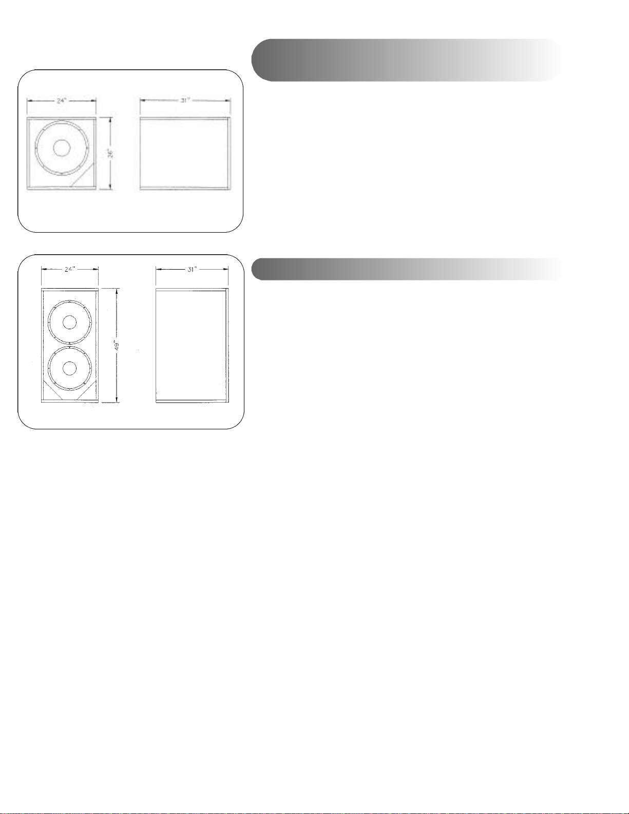
Fig. 22
Fig. 23
Mechanical Installation Drawings for KPT-484
and KPT-684
Please refer to figures. 22 and 23. These figures provide dimensions
required for creating baffles or for proper placement behind the screen.
Connectors can be made to the system by using the terminator panel
located on top of the unit.
KPT-484
Screen Sound System Setup and Alignment
After assembling the speakers, but prior to operation, be sure that wiring
connections are correct and that the installed systems are free from
problems, utilizing the following steps:
KPT-684
1) At the loudspeaker component end of the cable run, "short" the
positive and negative connections for each frequency section together,
and verify that your resistance meter reads the short when measured from
the amplifier end.
2) Verify that all amplifier channels and speaker components have been
wired correctly and are in proper polarity.
3) Set the electronic crossover and amplifier channels as per manufacturer
recommended settings. Refer to the speaker component specifications for
each system.
4) With a low level pink noise or frequency generator signal source, verify
that the low frequency amplifier and processor outputs for each of the
systems is feeding the proper speaker component(s). Do the same for all
of the amplifier and speaker sections, across all of the installed systems.
5) After pre-testing the system as indicated above, verifying operation and
completing a basic gain staging setup, to check for rattles, buzzes or
vibrations from the hardware, use a variable frequency oscillator or pink
noise source to "sweep" the system between 20Hz and 1000Hz at LOW,
MEDIUM, and then HIGH volume.
6) Complete a preliminary gain staging of the entire system per applicable
processor specifications, then verify that component aiming properly
addresses listening requirements throughout the house.
7) Complete proper final gain staging per processor recommendations.
Page 4
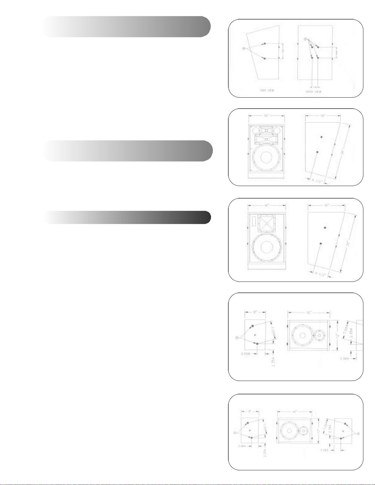
Mechanical Installation Drawings for KPT-250,
KPT-200 and KPT-100 Surround Sound Speakers
Please refer to the following drawings for installation details: Figures
17, 18, 19 and 20.
The bolt locations shown in "A" on Fig. 17 are common to models
KPT-250, KPT-200 and KPT-100 surround sound speakers, and are
used when mounting the speakers using a Goldberg bracket. The bolt
hole locations shown at "B" in Fig. 17 are used when mounting the
speakers using either an APC or OmniMount bracket.
Mechanical Installation Drawing for KPT-110
Surround Sound Speaker
Figure 21 shows the basic dimensions for the KPT-110. Location "A"
bolts and washers are to be used when mounting the speaker with a
Goldberg bracket.
Fig. 17
Fig. 18
Fig. 19
Surround Sound System Installation
Installation drawings for the surround sound speaker systems are
located in the following section. All of the systems are pre-assembled
for installation on-site, and include passive frequency dividing
networks. Please refer to the specification page for power and
impedance information.
Connections to the internal passive frequency dividing networks are
made on the termination panel located in the top of the units. Note
that models KPT-200 and KPT-100 include internal SMPTE/ISO 2696
X-curve de-emphasis.
Klipsch surround speaker mounting hardware is designed for readily
available Goldberg, APC and OmniMount brackets.
Fig. 20
Fig. 21
Page 5

Klipsch Professional Theater Speaker Systems
The hardware required to mount the component modules is included with the speaker
components on all Klipsch behind-the-screen and stage speaker systems. Hardware
primarily consists of brackets, yokes, bolts, nuts and washers for mounting and properly
aiming the mid-bass and high frequency horns and drivers above the low frequency
enclosures. The surround sound speakers, intended for wall mounting, are pre-drilled for
use with industry standard Goldberg, APC and OmniMount® brackets. Please refer to the
loudspeaker model installation diagrams in the following sections for specific assembly
details.
S a f e t y
After assembling the components on each speaker system, but before operation, all bolts
and nuts should be double-checked for proper seating and tightness. Due to the weight
and size of the components, damage could occur if the devices were to become
unattached.
A m p l i f i c a t i o n
For B-chain amplifier power matching, please refer to the specifications for each
component module. Amplifiers should be overrated to ensure available dynamic
headroom and freedom from distortion on loud signal passages. Level capabilities in the
house should meet or exceed your specific processor system standards when speaker
component specifications are factored in. Note that nominal dialogue levels in modern
theaters are typically 85dB or greater, with effect and music levels at a 105dB average.
When using passive crossovers (as opposed to actively dividing signals for the low,
mid-bass, high frequency and optional extended high frequency sections), Klipsch
recommends designing the system with 6dB of amplifier headroom.
Wire Gauge
The choice of gauge for speaker interconnect wire plays a major role in the power transfer
efficiency between amplifiers and speakers. Signal loss per distance charts for the various
gauges of speaker wire and loudspeaker impedances indicate that the largest gauge of wire
should be used, whenever possible, to minimize insertion loss, amplifier loading and
frequency response non-linearities.
C r o s s o v e r s
Although passive crossovers are available for a number of the Klipsch screen and stage
systems, there are advantages to using active crossovers. By actively dividing the frequency
sections for the systems, less power is lost to heat in the passive crossover, and device
control (damping factor) is greatly improved. In virtually every case, the speaker system
performance is improved through bi- or tri-amplification. Of course, the performance
improvements must be weighed against the cost of additional amplifier channels.
Page 6

Fig. 13
Fig. 14
Mechanical Installation Drawings for KPT-535
Please refer to the following drawings for assembly details:
Figures 13 and 14.
After unpacking all components, locate the KPT-402 compression driver
and horn. Attach the driver to the horn using supplied hardware.
Locate the two1/4"-20 screws on top of the KPT-904/940-LF. Remove the
two screws and washers. Place the KPT-402-MF unit on top of the KPT904/940-LF, making sure that the hole/slot as indicated by "A" in Fig. 13
lines up with the holes in the KPT-904/940-LF. Reinstall the screws and
washers. Adjust the horizontal angle as desired and tighten the screws.
Locate the KPT-Grand-HF. Locate the two1/4"-20 on the KPT-Grand-HF.
Remove the two screws and washers. Place the KPT-Grand-HF on top of
the KPT-402-MF and align the holes. Reinstall the screws and washers
and tighten screws as shown at "C" on Fig. 13.
Locate the 1/4"-20 nuts as shown at "D" in Fig. 13. To adjust the vertical
angle, loosen the nuts and adjust the horns until the desired vertical
angle is achieved. Tighten the nuts.
Fig. 15
Fig. 16
Mechanical Installation Drawings for KPT-325
Please refer to the following drawings for assembly details:
Figures 15 and 16.
After unpacking all the components, locate the two1/4"-20 screws on top
of the KPT-315-LF. Remove the two screws and washers. Place the KPT904-HF unit on top of the KPT-315-LF, making sure that the hole/slot as
indicated by "A" in Fig. 15 lines up with the holes in the KPT-315-LF.
Reinstall the screws and washers. Adjust the horizontal angle as desired
and tighten the screws.
Locate the 1/4"-20 bolts/nuts on both sides of the bracket as shown at "B"
in Fig. 15. To adjust the vertical angle, loosen the bolts and nuts and
adjust the horn until the desired vertical angle is achieved. Tighten the
bolts and nuts.
Page 7

Mechanical Installation Drawings for KPT-941
Please refer to the following drawings for assembly details:
Figures 9 and 10.
After unpacking all components, locate the KPT-941 HF
compression driver and horn. Attach the driver to the horn using
supplied hardware.
Locate the two1/4"-20 screws on top of the KPT-904/940-LF.
Remove the two screws and washers. Place the KPT-941-HF unit
on top of the KPT-904/940-LF, making sure that the hole/slot as
indicated by "A" in Fig. 9 lines up with the holes in the KPT904/940-LF. Reinstall the screws and washers. Adjust the
horizontal angle as desired and tighten the screws.
Locate the 1/4"-20 nuts as shown at "C" in Fig. 10. To adjust the
vertical angle, loosen the nuts and adjust the horn until the
desired vertical angle is achieved. Tighten the nuts.
Fig. 9
Fig. 10
Mechanical Installation Drawings for KPT-904
Please refer to the following drawings for assembly details:
Figures 11 and 12:
After unpacking all the components, locate the two1/4"-20 screws
on top of the KPT-904/940-LF. Remove the two screws and
washers. Place the KPT-904-HF unit on top of the KPT-904/940LF, making sure that the hole/slot as indicated by "A" in Fig. 11
lines up with the holes in the KPT-904/940-LF. Reinstall the
screws and washers. Adjust the horizontal angle desired and
tighten the screws.
Locate the 1/4"-20 bolts and nuts on both sides of the bracket as
shown at "B" in Fig. 11. To adjust the vertical angle, loosen the
bolts and nuts, and adjust the horn until the desired vertical angle
is achieved. Tighten the bolts and nuts.
Fig. 11
Fig. 12
Page 8

Optional passive crossovers are available for the following systems
KPT-941
KPT-535 (Mid-bass to high frequency only)
KPT-904
KPT-325
Recommended crossover frequencies for the various components can be found in the system specification section.
GE N E R A L AI M I N G GO A L S
Klipsch theater audio products utilize Tractrix® Horns in the screen and stage systems' mid-bass and high-frequency devices
for precise coverage and projection. By making the appropriate tilt-down adjustments on the supplied installation hardware,
and, if required, toeing-in the left and right outside speakers, you can achieve proper and precise vertical and horizontal aiming
of the system. The degree of toe-in will be determined by the depth and width of the auditorium, and the height and distance
of the screen from the seating area.
For localization to be effective, audience seating must fall inside the horizontal and vertical coverage patterns of the outside
high frequency horns. All Klipsch theater speaker systems utilize consistent coverage angles of 80 degrees or higher, with the
larger auditorium-appropriate systems providing nominal 90 degree coverage angles. Refer to the specification page for
component section coverage data.
BE H I N D- TH E- SC R E E N A N D STA G E SY S T E M S
Installation assembly drawings for the behind-the-screen and stage systems are located in the following section. All of the
systems are designed for assembly on-site and only require a few tools to complete. Electronic crossover frequency dividing
network specifications and delay settings are provided in the delay and crossover frequency section. Several of the systems have
optional passive crossovers available. Refer to the previous page for systems with available passive crossovers.
PL A C E M E N T CO N S I D E R AT I O N S
VE RT I C A L P O S I T I O N I N G
Behind-the-screen speaker systems should generally be located with the highest frequency horn section positioned at
approximately two-thirds the height of the perforated screen. The front edge of the high frequency horns, after tilt-down and
aiming, should be as close to the back of the screen as possible, without actually touching it. This will help ensure that a
minimal amount of back-reflection from the screen is created, minimizing "comb filter" frequency response anomalies.
HO R I Z O N TA L P O S I T I O N I N G
For proper localization, seating areas should fall inside the horizontal and vertical coverage patterns of the high frequency horn
devices. In L-C-R, three-channel, behind-the-screen systems, the speakers should be spaced an equal distance apart, with the
outside left and right speakers immediately inside of the unmasked screen area of the widest format projected (typically 2.35:1).
When the screen is masked to smaller formats (such as 1.85:1), acoustically transparent masking should be used to avoid
blocking of the high frequencies. In five-channel behind-the-screen systems, the speakers should be positioned equidistant
from each other across the stage.
The exact amount of toe-in and tilt will be determined by the depth and width of the auditorium, and the height and distance
of the screen from the seating area. The outside speakers' patterns (on axis) should cross two-thirds of the way to the rear. In
doing this, the audience members seated closer to the screen will be slightly off-axis when the speakers are aimed toward the
back wall, with levels balancing evenly owing to the inverse square distance law, front to rear. The Klipsch Tractrix® Horns in
the high-frequency and mid-bass sections will provide linear frequency response, although at reduced levels, as the listening
angle off-axis is increased, up to the pattern limits of the horn components.
Page 9

Mechanical Installation Drawings for KPT-MCM-4 Grand.
Please refer to the following drawings for assembly details:
Figures 1 and 2.
After unpacking all components, locate the KPT-941 HF compression
driver and horn. Attach the driver to the horn using supplied hardware.
Locate the two1/4"-20 screws on top of the KPT-XII. Remove the two
screws and washers. Place the KPT-941-HF unit on top of the KPT-XII,
making sure that the hole/slot as indicated by "B" in Fig. 1 lines up with
holes in the KPT-XII. Reinstall the screws and washers. Adjust the
horizontal angle as desired and tighten screws.
Locate the KPT-Grand-HF. Locate the two1/4"-20 screws on the KPTGrand-HF. Remove the two screws and washers. Place the KPT-GrandHF on top of the KPT-941-HF and align the holes. Reinstall the screws
and washers and tighten screws as shown at "D" in Fig. 1.
Locate the 1/4"-20 nuts as shown at "A" in Fig. 1. To adjust the
vertical angle, loosen the nuts and adjust horns until desired vertical
angle is achieved. Tighten nuts.
Fig. 1
Fig. 2
Mechanical Installation Drawings for KPT-MCM-3 Grand
Please refer to the following drawings for assembly details:
Figures 3 and 4.
After unpacking all components, locate the KPT-941 HF compression
driver and horn. Attach the driver to the horn using supplied hardware.
Locate the two1/4"-20 screws on top of the KPT-XII. Remove the two
screws and washers. Place the KPT-941-HF unit on top of the KPT-XII,
making sure that the hole/slot as indicated by "B" in Fig. 3 lines up
with the holes in the KPT-XII. Reinstall the screws and washers. Adjust
the horizontal angle as desired and tighten screws.
Locate the 1/4"-20 nuts as shown at "A" in Fig. 3. To adjust the vertical
angle, loosen the nuts and adjust the horn until the desired vertical
angle is achieved. Tighten the nuts.
Fig. 3
Fig. 4
Page 10

Fig. 5
Mechanical Installation Drawings for KPT-Jubilee™
Please refer to the following drawings for assembly details:
Figures 5 and 6:
After unpacking all the components, locate the two1/4"-20 screws on
top of the KPT-XII. Remove the two screws and washers. Place the KPT904-HF unit on top of the KPT-XII, making sure that the hole/slot as
indicated by "A" in Fig. 5 lines up with the holes in the KPT-XII.
Reinstall the screws and washers. Adjust the horizontal angle as desired
and tighten screws.
Fig. 6
Fig. 7
Locate the 1/4"-20 bolts/nuts on both sides of the bracket as shown at
"B" in Fig. 5. To adjust the vertical angle, loosen the bolts and nuts, and
adjust the horn until the desired vertical angle is achieved. Tighten
bolts and nuts.
Mechanical Installation Drawings for KPT-941-T
Please refer to the following drawings for assembly details:
Figures 7 and 8.
After unpacking all components, locate the KPT-941-T compression
driver and horn. Attach the driver to the horn using supplied hardware.
Locate the two1/4"-20 screws on top of the KPT-904/940-LF. Remove
the two screws and washers. Place the KPT-941-T-HF unit on top of the
KPT-904/940-LF, making sure that the hole/slot as indicated by "A" in
Fig. 7 lines up with the holes in the KPT-904/940-LF. Reinstall the
screws and washers. Adjust the horizontal angle as desired and tighten
the screws.
Fig. 8
Locate the 1/4"-20 nuts as shown at "C" in Fig. 7. To adjust the vertical
angle, loosen the nuts and adjust the horn until the desired vertical
angle is achieved. Tighten the nuts.
Page 11

Fig. 24
Page 12

Klipsch Professional Theater Speaker Systems
Installation Manual
Applicable for the Installation and assembly of the following products:
Screen Systems
KPT-MCM Grand
KPT-Jubilee® Stage System
KPT-941-T (THX® – Approved)
KPT-941
KPT-535
KPT-904
KPT-325
Surround Systems
KPT-250
KPT-200 (THX® – Approved)
KPT-100 (THX® – Approved)
KPT-110
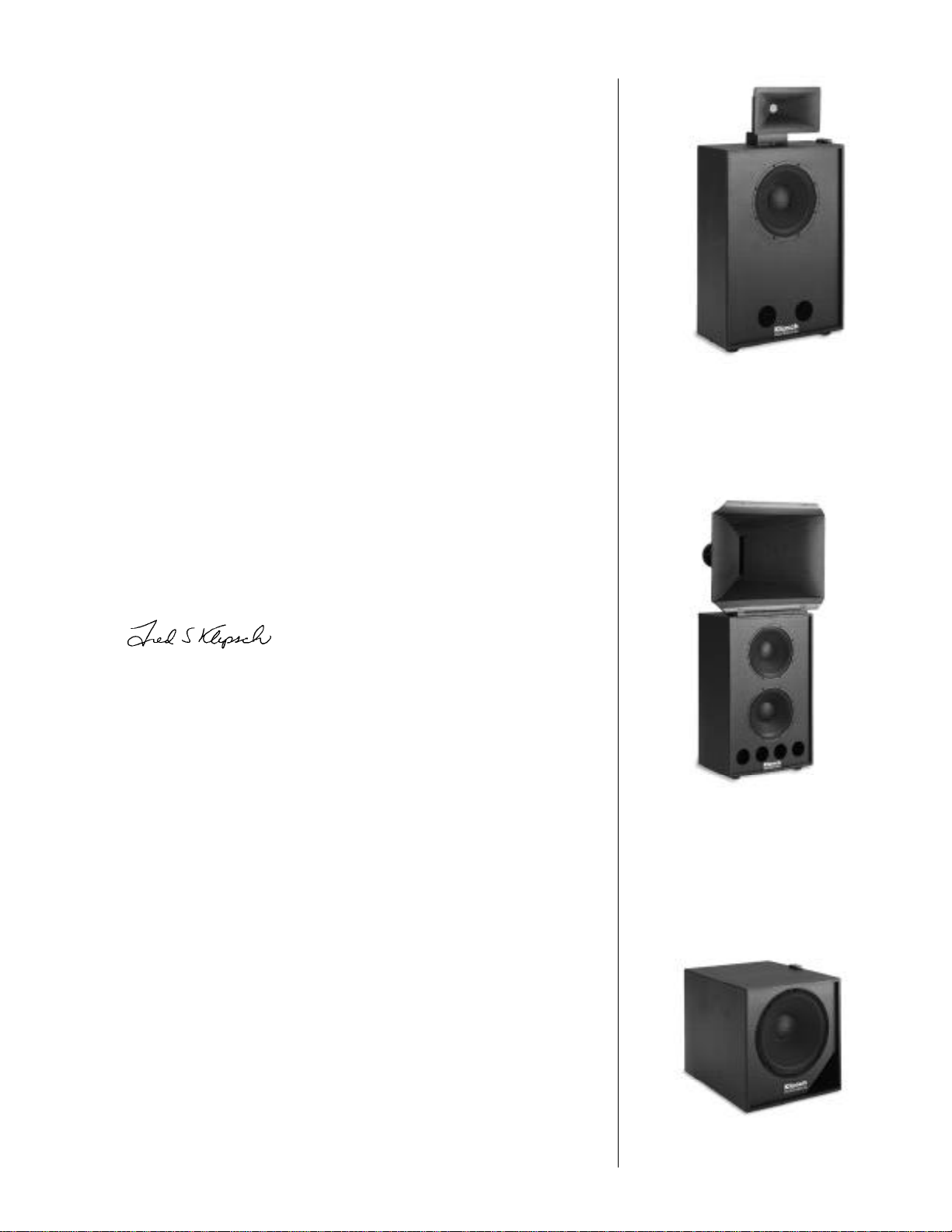
SU B W O O F E R S
KPT-684 (THX® – Approved)
KPT-484
 Loading...