

Page 1

CS-500
Owner's Manual
Page 2

Table of Contents
Chapter 1: Connecting Your System
Reading this Manual ......................................................................1
Step-by-Step Connections .............................................................1
Step 1: Unpack the box ..................................................................2
Step 2: Put the batteries in the remote control .............................2
Step 3A : Set-top box connection ...................................................3
Step 3B: TV audio connection ........................................................4
Step 4: Connect Klipsch System to the TV's Input .........................5
Step 5: Connec t the speakers ........................................................6
Speaker Setup Considerations ................................................6
Step 6: Connect other components (OPTIONAL) ...........................7
Step 7: Connect AM and FM antennas ...........................................8
Step 8: Turn on the T V and the Klipsch system ..............................8
Step 9: Complete the on-screen setup ..........................................9
Your Klipsch Controller .................................................................11
Buttons .................................................................................11
Display ..................................................................................11
The basics ................................................................................... 12
Switching between media .................................................... 12
Chapter 2: Remote Control
Butt on s ........................................................................................ 13
Programming your remote control ............................................... 14
Chapter 3: Operation
Compatible discs ........................................................................ 15
Incompatible discs ...................................................................... 15
Regional coding ........................................................................... 15
Playing a disc .............................................................................. 15
DVD and VCD playback.................................................................16
Transpor t ...............................................................................16
Navigating info banners ...............................................................17
Playing CDs ................................................................................. 18
Playing CDs with mp3 or JPEG files ............................................. 18
Playing content from a USB drive ................................................ 18
Listening to the tuner .................................................................. 19
Setting tuner presets ........................................................... 19
Chapter 4: Menu System
On screen menu system .............................................................. 20
Navigating menus ........................................................................ 20
On-screen menus .........................................................................21
Audio .....................................................................................21
Setup ....................................................................................21
Language s .............................................................................21
Parental control ................................................................... 22
Remote control .................................................................... 22
Chapter 5: Troubleshooting
General problems ................................................................. 23
Video problems .................................................................... 23
Audio problems .................................................................... 23
Remote control problems ..................................................... 23
Playback problems ............................................................... 23
Radio problems .................................................................... 23
Chapter 6: Care and Maintenance
Klipsch System..................................................................... 24
Cleaning ............................................................................... 24
Handling and Caring for Discs .............................................. 24
Remote Control Codes ......................................................... 25
Warranty ............................................................................... 27
FCC Information ................................................................... 27
Appendix I
Connection Overview ................................................................... 28
Input jacks ........................................................................... 28
Output jacks ......................................................................... 28
Audio connection options .................................................... 28
Video connection options .................................................... 28
Page 3
Important Safety Information
INDEX page i/ii
1.
READ these instructions.
2.
KEEP these instructions.
3.
HEED all warnings.
4.
FOLLOW all instructions.
5.
DO NOT use this apparatus near water.
6.
CLEAN ONLY with dry cloth.
7.
DO NOT block any ventilation openings. Install in accordance with the
manufacturer’s instructions.
8.
DO NOT install near any heat sources such as radiators, heat registers,
stoves, or other apparatus (including amplifi ers) that produce heat.
9.
DO NOT defeat the safety purpose of the polarized or grounding type
plug. A polarized plug has two blades with one wider than the other. A
grounding type plug has two blades and a third grounding prong. The
ider blade or the third prong is provided for your safety. If the provided
w
plug does not fi t into your outlet, consult an electrician for replacement of
the obsolete outlet.
10.
PROTECT the power cord from being walked on or pinched, particularly
at plugs, convenience receptacles, and the point where they exit from
the apparatus.
11.
ONLY USE attachments/accessories specifi ed by the manufacturer.
12.
USE only with a cart, stand, tripod, bracket, or table specifi ed by the
manufacturer, or sold with the apparatus. When a cart
is used, use caution when moving the cart/apparatus
combination to avoid injury from tip-over.
13.
UNPLUG this apparatus during lightning storms or when
unused for long periods of time.
14.
REFER all servicing to qualifi ed service personnel. Servicing is required
when the apparatus has been damaged in any way, such as power-supply
cord or plug is damaged, liquid has been spilled, objects have fallen into
the apparatus, the apparatus has been exposed to rain or moisture, does
not operate normally, or has been dropped.
WARNING:
To reduce the risk of fire or electrical shock, do not expose this
apparatus to rain or moisture.
WARNING: Batteries (battery pack or batteries installed) shall not be exposed to
excessive heat such as sunshine, fi re or the like.
WARNING: No naked fl ame sources – such as candles – should be placed on
the product.
WARNING
RISK OF ELECTRIC SHOCK.
DO NOT OPEN.
WARNING : Do Not Open! Risk of Electrical Shock. Voltages in this equipment
are hazardous to life. No user-serviceable par ts inside. Refer all servicing to
qualified service personnel.
CAUTION: Place the equipment near a main power supply outlet and make sure that
you can easily access the power breaker switch.
WARNING: This product is intended to be operated ONLY from the AC Voltages listed
on the back panel or included power supply of the product. Operation from voltages
other than those indicated may cause irreversible damage to the product and void
the product's warranty. The use of AC Plug Adapters is cautioned because it can
allow the product to be plugged into voltages in which the product was not designed
to operate. If the product is equipped with a detachable power cord, use only the
type provided with your product or by your local distributor and/or retailer. If you are
unsure of the correct operational voltage, please contact your local distributor and/or
retailer.
NOTE: If a DVD is present, the following laser safety statement applies:
LASER SAFETY: This unit employs a laser. Due to possible eye injury, only a
qualified service person should remove the cover or attempt to service this device.
For Your Safety: The AC power plug is polarized ( one blade is
wider than the other) and only fits into an AC power outlet one
way. If the plug won’t go into the outlet completely, turn the plug
over and try to insert it the other way. If it still won’t fit, contact a
qualified electrician to change the outlet, or use a different one.
Do not attempt to bypass this safety feature.
DO NOT expose this apparatus to dripping or splashing and ensure
15.
that no objects fi lled with liquids, such as vases, are placed on the
apparatus.
16.
To completely disconnect this apparatus from the AC Mains, disconnect
the power supply cord plug from the AC receptacle.
17.
The mains plug of the power supply cord shall remain readily operable.
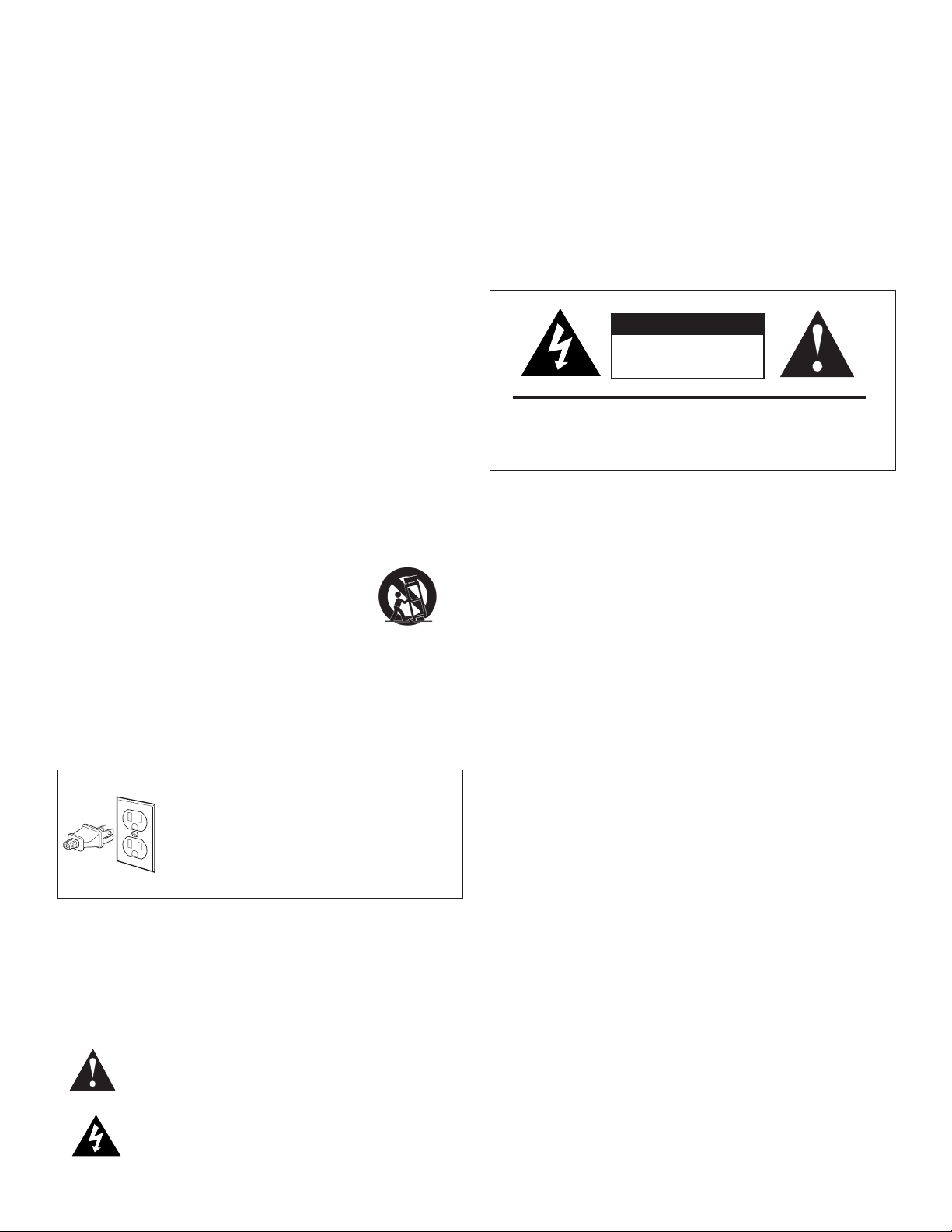
The exclamation point, within an equilateral triangle, is intended to alert the
user to the presence of important operating and maintenance ( servicing)
instructions in the literature accompanying the product.
The lightning flash with arrowhead symbol within an equilateral triangle,
is intended to alert the user to the presence of uninsulated “dangerous
voltage” within the product’s enclosure that may be of sufficient magnitude to
constitute a risk of electrical shock to persons.
CAUTION: Use of controls or adjustments or performance of procedures other than
those specified herein may result in hazardous radiation exposure.
This device is protected by U.S. patent numbers 4,631,603 and 4,577,216 and
4,819,098 and 4,907,093 and other intellectual property rights.
DVD Safety Information
This DVD player is designed and manufactured to respond to the Region Management Information. If the
region number of a DVD disc does not correspond to the region number of this DV D player, this player
cannot play the disc. The region number for this DVD player is Region No 1.
DVD Copy Protection
In accordance with the DVD st andard, your DVD player is equipped with a Copy Protection System,
which can be switched on and off by the DVD disc itself, in order to make any recording of the relevant
DVD disc onto a videotape of ver y poor picture quality, or even impossible. This product incorporates
copyright protection technology that is protected by method claims of certain U.S. patents and other
intellectual property rights owned by Macrovision Corporation and other rights owners. Use of this
copyright protection technology must be authorized by Macrovision Cor poration, and is intended
for home use only unless otherwise authorized by Macrovision Corporation. Reverse engineering or
disassembly is prohibited. This DVD player does not play discs that are pirated. The unauthorized use
and recording of copyright and patented material is considered piracy.
Page 4

Thank You
Thank you for purchasing the Klipsch CS-500 System. After reading this
manual and connecting your system, you will hear the results of more than 60
years of stringent engineering and class-leading research and development.
Like all Klipsch products, your Klipsch CS-500 features Klipsch Tractrix
loaded technology—the guiding design for the fi rst Klipschorn
1946 and every product that has followed. Horn-loading allows your speakers
®
®
Horn-
developed in
to deliver high sensitivity, low distortion, fl at frequency response and wide
dispersion, which translates to unequaled power, detail, and dynamics: the
hallmark of the “Klipsch Sound.” Please be sure to return the enclosed product
registration card or register your product at www.klipsch.com so we are better
able to serve you. Again, thank you for choosing Klipsch and we hope that your
Klipsch CS-500 brings life to your music and movies for many years.
Reading this Manual
This manual uses different style conventions and typefaces to distinguish them from the body text. Throughout the manual, the following conventions are used:
Text
Button names on the remote and unit appear in
CAPS, BOLD
On-screen menus appear in Bold, Italics.
Input and output jack names appear in
.
ALL CAPS
ALL
.
Example
DISC, AUX 1, SAT/CAB, GUIDE, INFO, DVD MENU
Audio, Setup, Languages, Parental Control
AUX 1 INPUT, VIDEO OUTPUT, COMPONENT
Black bar sections provide technical information.
Input and Output Jacks
CHAPTER 1: CONNECTING YOUR SYSTEM
Step-by-Step Connections
This chapter is divided into steps to get you up and running as quickly as possible. Because TVs have so many different options these days, several
connection scenarios are provided. Below is a summary of the steps you will take to get connected.
Step 1: Unpack the box Page 2
Step 2: Put batteries in the remote control Page 2
Step 3: Connect TV signal output to Klipsch input
3A: Set-top box Connection Page 3
Use this connection if your TV has a cable box, satellite receiver, or HD Receiver set-top box connected to it
3B: TV Audio Connection Page 4
Use this connection if you receive your TV signal via regular cable (no cable box) or an off-air antenna
Step 4: Connect Klipsch system to TV’s VIDEO INPUT Page 5
Step 5: Connect the speakers Page 6
Step 6: Connect other components Page 7
Step 7: Connect AM and FM antennas Page 8
Step 8: Turn on TV and Klipsch system Page 8
Step 9: Complete the on-screen setup Page 9
Page 5

STEP 1: Unpack the box
Make sure you have the following items as you unpack your Klipsch system.
CONNECTIONS page 1/2
0
0
Remote Control
0
AM Antenna
0
Subwoofer Left/Right SpeakersController
0
2 AA Remote Batteries
0
2 20-Ft. Left/Right
Speaker Cables
Step 2: Put the batteries in the remote control
1.
2.
3.
4.
0
0
Setup Guide
00
Composite Video
Cable (Yellow)
0
15-Ft. Subwoofer
Speaker Cable
Locate supplied remote control and batteries.
Remove the battery compartment cover on the back of the remote. Push down on the
ab and lift the cover.
t
Insert the two (2) “AA” batteries. Make sure the polarities (+ and -) are aligned
correctly with the polarities inside the remote.
Replace the cover.
Left/Right Audio Cable
(Red and White)
0
Mini plug to
RCA Adapter
0
Owner’s Manual
0
FM Antenna
0
Rubber Pads
Page 6
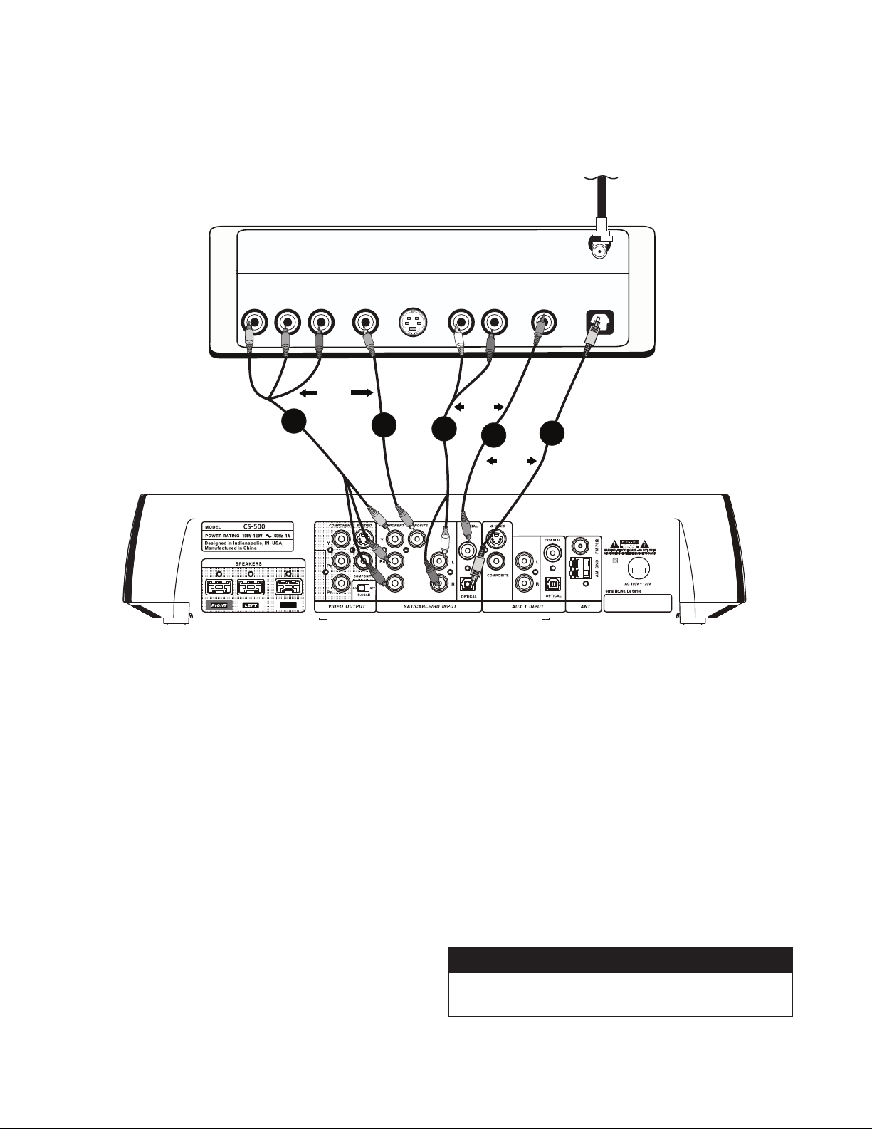
STEP 3A: Set-Top Box Connection
Use this connection if your TV has a cable box, satellite receiver or HD receiver set-top box connected to it.
See next page (3B) if no set-top box is used.
CABLE BOX (shown)
O U T P U T S
COMPONENT
Y PB PR
VIDEO S-VIDEO
AUDIO
L R
CABLE SIGNAL
CABLE IN
DIGITAL
COAXIAL OPTICAL
OR
2A
KLIPSCH CONTROLLER
SUB
Disconnect the cable on your cable, satellite or HD set-top box that is
1.
connected to your TV (you need to connect 1 video and 1 audio).
Connect the VIDEO—look at the options available on the set-top box
2.
and choose 2A or 2B.
To maintain best picture quality—if the back of the set-top box has
A.
COMPONENT VIDEO (
cables (either a bundled set or three video grade cables) into those
jacks on the set-top box and to the Klispch system’s
INPUT COMPONENT
option, you must also connect the corresponding Y, P
from the Klipsch controller’s “VIDEO OUTPUT” section to your TV to
ensure that you get a picture. These cables have not been included
with the Klipsch system.
If the set-top box has a VIDEO (yellow)
B.
the yellow video cable into that jack and to the Klipsch system’s
SAT/CABLE/HD INPUT COMPOSITE
Y, PB, P
R)
OUTPUT
jacks, plug corresponding
SAT/CABLE/HD
jacks (Y to Y; PB to PB, PR to PR). To use this
B, PR OUTPUT
OUTPUT
jack for video, plug
(yellow) jack.
2B
OR
3A
3B
3C
OR
Connect the AUDIO—look at the options available on the set-top box
3.
and choose 3A, 3B, or 3C.
Connect audio cables to the AUDIO LEFT (white) and AUDIO
A.
RIGHT (red) jacks on the back of the set-top box and to the Klipsch
system’s
B.
If the set-top box has Digital Audio (
cable to the set-top box AUDIO COAXIAL OUTPUT jack and to the
SAT/CABLE/HD INPUT COAXIAL
C.
If the set-top box has Digital Audio (
cable (not supplied) to the Klipsch System’s
OPTICAL
Note: If you connect a high definition Y, PB, PR INPUT, you must also
connect the corresponding Y, P
Please see appendix I (page 28) for the basics on how input
and output jacks work with your Klipsch system.
SAT/CABLE/HD INPUT Left (
jack. You will fi rst need to remove the plastic dust plug.
B
, PR OUTPUT to your TV.
jack.
white) and
COAXIAL
), connect appropriate
OPTICAL
), connect appropriate
SAT/CABLE/HD INPUT
Right
(red) jacks.
Input and Output Jacks
Page 7

STEP 3B: TV Audio Connection
Use this connection if you receive your TV signal via regular cable (no cable box) or with an off-air antenna.
TV BACK PANEL
CONNECTIONS page 3/4
COMPOSITE
INPUT 1
R
L
V
S-VIDEO
INPUT 2
R
L
V
S-VIDEO
KLIPSCH CONTROLLER
SUB
COMPONENT
INPUT 3
Y
P
B
P
R
DIGITAL COAXIAL
OUTPUT
1B
INPUT 4
Y
P
B
R
P
DIGITAL OPTICAL
OUTPUT
OR
COMPONENT
OUTPUT
Y
P
B
R
P
ANTENNA
INPUT
1C
OR
AUDIO / VIDEO
OUTPUT
R
L
V
ANTENNA B
INPUT
1A
CABLE OR
OFF-AIR
ANTENNA
If you don't have a set-top box connected to your TV (you either have cable
coming out of the wall or an off-air antenna, such as HD), simply connect
the AUDIO OUTPUT jacks on the TV to the AUDIO INPUT jacks on the Klipsch
system. If you want the TV sound to come through the Klipsch system, you
need to make this audio connection.
Choose the best T V AUDIO connection available (1A, 1B, or 1C).
1.
I
A.
f your TV doesn’t have DIGITAL OPTICAL or DIGITAL COAXIAL
for the audio connection, connect standard audio cables (you can
use the supplied cables for this if you have not already used them)
to the AUDIO LEF T (white) and AUDIO RIGHT (red) OUTPUT jacks
on the back of your TV and to the Klipsch system’s
INPUT
jacks that are labeled L and
R.
SAT/CAB/HD
If your TV has a DIGITAL AUDIO (
B.
COAXIAL
) OUTPUT jack, connect
appropriate cable (not supplied) to the TV’s AUDIO COAXIAL
OUTPUT jack and to the Klipsch System’s
COAXIAL
jack.
C.
If your TV has a DIGITAL AUDIO (
SAT/CAB/HD INPUT
OPTICAL
) OUTPUT jack, connect
appropriate cable (not supplied) to it and the other end to the
Klipsch System’s
SAT/CAB/ HD INPUT OPTICAL jack.
2. Make note of which AUDIO INPUT you used ( SAT/CAB, AUX 1, AUX 2),
as you will need to enter the correct AUDIO INPUT settng during the
on-screen setup procedure in Step 9.
Input and Output Jacks
Please see appendix I (page 28) for the basics on how input
and output jacks work with your Klipsch system.
Page 8

STEP 4: Connect Klipsch System to the TV's Input
TV BACK PANEL
COMPOSITE
INPUT 1
R
L
V
S-VIDEO
OR
1
INPUT 2
R
L
V
2
OR
COMPONENT
INPUT 3
Y
P
B
P
R
DIGITAL COAXIAL
OUTPUT
3
INPUT 4
Y
P
B
R
P
DIGITAL OPTICAL
OUTPUT
COMPONENT
OUTPUT
Y
P
B
R
P
ANTENNA A
INPUT
4
AUDIO / VIDEO
OUTPUT
R
L
V
ANTENNA B
INPUT
KLIPSCH CONTROLLER
SUB
If your TV doesn’t have COMPONENT, but has S-VIDEO, connect
1.
S-VIDEO cable (not supplied) to the Klipsch system’s
S-VIDEO
jack and to the corresponding
2.
If your TV has COMPONENT INPUT jacks ( Y, P
S-VIDEO
VIDEO OUTPUT
jack on the TV.
B, PR ) connect the (not
supplied) corresponding cables (either bundled or three separate
video grade cables—yellow) to the Klipsch system’s
COMPONENT Y, P
B
, P
R jacks and to the corresponding input jacks on
VIDEO OUTPUT
the TV. To use this option, you must also connect the corresponding Y,
P
B, PR OUTPUT to your TV.
3.
If your TV doesn’t have COMPONENT or S-VIDEO, connect the TV’s
VIDEO INPUT
(yellow) to the Klipsch system’s
COMPOSITE
jack (yellow)
with the supplied cable.
If you’re using COMPONENT jacks and your TV supports progressive
4.
scanning technology (see the TV owner’s manual if you don’t know
whether your TV is a progressive scan TV), slide the
on the back of your Klipsch system to the
ON
P. SC A N
switch
position. If you put the
P. SC A N switch in the ON position and your TV doesn’t support
progressive scan, you won’t see a picture on the TV screen.
Note: Until recently, TVs only had VIDEO INPUT jacks. Therefore, your TV
might not carry the "IN" or "Input" label even though it is an input.
Input and Output Jacks
Please see appendix I (page 28) for the basics on how input
and output jacks work with your Klipsch system.
Page 9

STEP 5: Connect the Speakers
SUB
RIGHT
SPEAKER
LEFT
SPEAKER
SUBWOOFER
KLIPSCH CONTROLLER
CONNECTIONS page 5/6
After you uncoil the speaker cable, connect one speaker to the
1.
(Red) connector on the back of your Klipsch system. This speaker will
be to your left when you are behind the system connecting, but it will
be on the right when you are facing the system. You can connect either
speaker to the
LEFT
or the
RIGHT
OUTPUT, you just need to place them
properly.
Connect the other speaker to the
2.
the Klipsch system. The speaker connected to the
LEFT
(White) OUTPUT on the back of
LEFT
OUTPUT will be
to your right when you are behind the system connecting, but it will be
on the
left
when you are facing the system.
SUB
3.
Connect the subwoofer to the
(Blue) OUTPUT jack on the back of
your Klipsch system.
Rubber pads have been included in the Accessory box. These self
4.
adhesive pads can be applied to the bottom of the speakers.
Input and Output Jacks
Please see appendix I (page 28) for the basics on how input
and output jacks work with your Klipsch system.
RIGHT
Speaker Setup Considerations
•
•
•
•
•
•
•
•
•
6' 15'
TELEVISION
Front speakers typically sound best
SUB
RL
when their tweeters are at approximately ear height for seated listeners.
If this isn’t possible, it is sometimes
benefi cial to tilt the speaker down or
up slightly so that it is aimed into the
listening area.
If possible, position the speakers the same distance apart as they are
from the listening position.
If you are putting speakers in a cabinet, on a rack or a table, try to
bring them out far enough so that they are at least fl ush with the
cabinet’s front edge.
When practical, arrange each speaker so that it is at somewhat
different distances from the fl oor, the wall behind it, and the wall
beside it. It can also help to have the left and right front speakers
at different distances from their nearest side walls. This staggering
helps smooth the bass range.
Each speaker can be set on its bottom or side. If you set them on the
side and want to turn the Klipsch logo, carefully pull the logo forward,
turn and release it.
Satellites should be positioned so that no obstruction is within 1½”-2” of
the rear port. Blocking the port could result in diminished sound quality
The subwoofer’s output will increase as it is moved closer to walls,
with maximum output when it is placed in a corner. If practical,
al
ways place the subwoofer near a wall. Additionally, a subwoofer will
deliver the smoothest bass response when placed near a wall away
from openings, such as doors.
Maintain a distance of at least three (3 ) feet between the subwoofer and
a CRT (tube) television so as to avoid interference with your television
Naturally, there are exceptions to the rules, since no two rooms or
systems are exactly alike. Experiment with positioning to get the
best sound.
Page 10

STEP 6: Connect other components (OPTIONAL)
VCR Back Panel
INPUT
L R
AUDIO VIDEO S-VIDEO
AUX 2 - Side Panel
KLIPSCH CONTROLLER
R AUDIO L VIDEO S VIDEO
You can connect other components, such as a VCR, another recording device
(like a hard-disk drive product or DVD Recorder), or a video game system to
your Klipsch system using the AUXILIARY (
AUX
) INPUTS.
RF IN
RF OUT
L R
OUTPUT
2
SUB
1
Connecting headphones to Headphone OUTPUT
For private listening, connect compatible headphones to the
jack on the side of the Klipsch system.
HEADPHONE
Connecting a component to AUX 1 INPUT
From the component’s output jacks, connect the best available video
1.
option to the Klipsch system’s
2.
Do the same thing for the audio connection. Choose the best available
connection from the component’s AUDIO OUTPUT jacks, and connect
appropriate cables. Connect the cable(s) to the Klipsch system’s
INPUT
audio jacks.
AUX 1 INPUT
video jacks.
AUX 1
Connecting a component to AUX 2 INPUT (side)
The
AUX 2 INPUT
for convenience when connecting temporary components, such as a video
game system or a digital camera/camcorder.
From the component’s output jacks, connect the best available
1.
vi
deo option.
Do the same thing for the audio connection. Choose the best available
2.
connection from the component’s output jacks, and connect the
appropriate cable.
jacks on the side of your Klipsch system were designed
Connecting a device with USB to USB connector
Connect a device with
INPUT
connector. This port is only for compatable USB fl ash memory drives.
It is not suitable for direct connecton to a computer.
Note: This USB port is a part of the "DISC" Source, not Aux 2.
USB OUTPUT
to the Klipsch system’s
Input and Output Jacks
Please see appendix I (page 28) for the basics on how input
and output jacks work with your Klipsch system.
USB
Page 11

STEP 7:
CONNECTIONS page 7/8
Connect AM and FM Antennas (supplied)
OR
75Ω
AM GND
KLIPSCH CONTROLLER
SUB
The back of your Klipsch System has jacks for the AM and FM antennas that
were packed with your system. Unwind the wires for each antenna to provide
the best reception. An outdoor antenna may be used in place of the supplied
indoor antennas. To add an outdoor antenna, consult a qualified installer.
Follow all safety instructions supplied with the antenna.
FM Antenna
Plug the FM antenna into the Klipsch system’s FM (75Ω) jack in the section
labeled
ANT.
On the back of your Klipsch system spread out the antenna
arms and move them around to establish optimum FM reception. Extend the
antenna as much as possible.
Some cable TV providers make FM radio signals available through the cable
s
ervice to your home. This connection is made to the external FM jack on
the back of the Klipsch system. To connect to this service, contact your
cable TV provider for assistance.
Make sure that the cable radio installation includes a TV/FM splitter so that
only the FM radio band, not the cable TV band, is received by the Klipsch
system. If necessary, contact your cable company.
AM Antenna
Plug the AM loop antenna into the
on the back of your Klipsch system. Place the antenna loop at least 20 inches
(50 centimeters) away from your Klipsch system. To get optimum
reception, you may need to experiment with the positioning of the
loop antenna.
AM GND
jack in the section labeled
ANT
STEP 8:
1.
2.
3.
Turn on the TV and the Klipsch System
Plug in the Klipsch system’s power cord to an AC power outlet.
Turn on the Klipsch system (press the
front panel or on the remote control). You can also press
the remote.
Turn on the TV and tune to the correct video input channel. This is
the channel that corresponds to the
of the TV to connect the Klipsch system. The name and how you
access this video input channel varies for different TVs. Generally,
you will press a button on the TV’s remote control, such as source
or input or vid. See below if you can’t fi nd the correct input channel
on your TV.
ON/OFF
input
button on the
jack you used on the back
Set TV to the Right Channel
If you do not see a picture on your T V, check your TV's owner manual to see
how you tune the TV to the correct channel. It won't be "Channel 3" but it's
the same idea. You'll need to tune the TV to the "channel" that matches the
input jacks on the TV you used to connect to the Klipsch system's
(either COMPONENT, S-VIDEO, or COMPOSITE—which is regular VIDEO and
color-coded yellow). Below are some ideas to try if you can't find the answer in
the TV manual.
Button on T V Remote Channel Number of TV Button on TV
SOURCE
INPUT
LINE
VIDEO
VID
00 90 91
92 93 VID 1
VID SVID CMPNT
You might have to press
the TV's channel down
button until you get to the
correct video channel.
DISC
output
SOURCE
INPUT
LINE
VIDEO
VID
on
jacks
Page 12

STEP 9:
Complete the On-screen Setup
Press
MENU
on your Klipsch system remote control (the main menu appears).1.
Press arrow down Ç to highlight Setup and press
2.
items appear).
Match the on-screen option with the cables that are connected to each of the
jacks on your Klipsch system. This information tells the system what is connected
to it, and which cables and jacks were used.
TV Audio Connection: If you made a TV Audio connection, use the arrow
3.
button to select where you connected the TV’s AUDIO OUTPUT to the Klipsch
system’s AUDIO INPUT. Use the
option and press
SAT/CABLE/HD: Choose this option if you connected audio from the
TV to one of the three AUDIO INPUT options in the
section on the back of the Klipsch system.
AUX 1: Choose this option if you connected audio from the TV to one of
the audio options in the
system.
ENTER
Å
or Ç arrow button to highlight the correct
.
AUX 1 INPUT
section on the back of the Klipsch
ENTER
(the Setup menu
SAT/CABLE/HD INPUT
AUX 2: Choose this option if you connected the TV’s audio to one of the
AUX 2 INPUT
No Audio Connection: Choose this option if you didn’t connect the
audio from the TV to the Klipsch system. You’ll only hear audio from the
Klipsch system when you’re playing the radio or a disc, or through one of
the components connected to the Klipsch System (e.g., VCR, DVD Recorder,
mp3 player, etc.).
audio options on the side of the Klipsch system.
Note: If you connected the audio from the TV's AUDIO OUTPUT jacks to the Klipsch
system, you'll need to turn off your TV's internal speakers and may need to adjust
the audio setting in the TV's menu system. Locate your TV manual to get specific
instructions, as the procedures differ for different brands and types of televisions.
Page 13

CONNECTIONS page 9/10
TV Format: TV Format lets you choose between a standard TV screen and
4.
a Widescreen option. The Widescreen option has an aspect ratio of 16:9. If
your TV has a 4:3 aspect ratio, select either the Standard or Letterbox option
depending on your preference.
RDS (Radio Data System): RDS is the system that allows broadcasters
5.
to embed programming information into the radio signal, such as the name of the
artist or song. Your Klipsch system is RDS-enabled.
If you want to turn on RDS, choose On (the name of the radio station will appear
on the Klipsch display). Press
ENTER
to activate your choice.
Note: On most U.S. radio stations, artist and title information will appear with the
“Station ID.”
Page 14

Your Klipsch Controller
Buttons
SOURCE
PRESETS
PLAY/PAUSE
Ç
Ç
OPEN/CLOSE
POWER
VOLUME
Ç
TUNING
Ç
SOURCE TUNING PRESETS
Ç
Ç
Chooses the function you want to use—radio,
DVD/CD, watch TV, access any other components
connected to your Klipsch system (VCR, video game
system, etc.). Each time you press the
SOURCE
button, it goes to the next input that corresponds
to the component that’s connected to that
input
jack on the back of your Klipsch system.
When listening to the radio, this button moves to the
next radio station that you programmed into the
preset memory.
Plays discs in disc tray, and pauses playback
when a disc is playing.
Opens and closes the disc tray.
Turns your Klipsch system on and off.
Adjusts the volume.
Changes radio station. Specifi c functionality of these
buttons can be selected in the tuner setup menu.
PLAY/PAUSE OPEN/CLOSE
Ç
Ç
VOLUME
POWER
Display
DVD
D I G I T A L
DOLBY
A
PROG
CD
The display on the front of your Klipsch system provides playback
information. The display illuminates each option that is active for the type of
media you are playing. The numbers on the display let you know the track,
title, and/or chapter number of the disc. Additionally, information from the
radio’s RDS (Radio Data System), such as artist and track information, is
displayed when you’ve tuned to the radio function. Below are explanations of
display messages you may encounter that may not be covered in other parts
of this manual.
P.SCAN MP3 WMA MPEG4 JPEG ANGLE TITLE TRK CHAP
B ALL
RANDOM
Dolby® Digital
The trademarked marketing name for Dolby Laboratories’ AC-3 codec. The
common version contains six total channels of sound, with fi ve channels
for normal-range speakers (Right Front, Center, Left Front, Right Rear and
Left Rear) and one channel for the subwoofer. The Dolby Digital format also
supports Mono and Stereo. Your Klipsch system supports Dolby Digital with
its 2.1 audio system design.
DTS (Digital Theatre Systems)
A multi-channel surround sound format (rival of Dolby Digital). With DTS, the
encoders and decoders support numerous channel combinations and stereo.
DTS contains four-channel+LFE (Low Frequency Effects) audio tracks. Digital
Theatre Systems was the name of the company that developed this format
(currently referred to as DTS). Film director Steven Spielberg was one of the
company’s initial investors. Spielberg fi lms use the DTS audio format.
P.SCAN (Progressive Scan)
Lights if the
position.
P. SC A N
switch on the back of the Klipsch system is in the ON
Page 15

The Basics
CONNECTIONS page 11/12
Switching between media—TV, DVD, Radio, CDs, etc.
Your Klipsch system is the center of your entertainment room...now, you just need to understand
how to get from one type of entertainment to another.
the corresponding button on the remote control (
SOURCE
When you turn on your Klipsch system, it tunes to the last source you used. The front panel
indicates what source is active.
DISC
AM/FM Radio
SAT/CAB Watching TV from a set-top box (cable, satellite, HD receiver)
AUX 1
AUX 2
TV
on the front of your Klipsch system to access the different options.
DVD or CD
Component connected to AUX I INPUT jacks (e.g., TV or VCR)
Component connected to the jacks on the side of the unit
Watching TV without a set-top box connected
To move to a different type of media, press
DISC, AM/FM, SAT/CAB
) or keep pressing
Progressive Scan TVs
On the back of your Klipsch CS-500 system, there is a progressive scan switch labeled
P. SC A N
can use to read and display broadcast signals. Progressive scan TVs display each pixel (picture
element) of the signal consecutively line by line. All progressive scan TVs are digital, but not all
digital TVs are progressive scan.
. Progressive scan is a result of the digital TV transition—it is a process digital TVs
Some digital TVs only support the classic interlace display method that TVs have used since
their inception. With interlace scanning, a TV draws every other line of the broadcast signal—
fi rst, the even numbered lines and then the odd numbered lines. This process happens so
quickly it tricks your eye so it appears as though you're seeing the entire picture.
ON
OFF
P.SCAN
If your digital TV is progressive scan, turn the
use the COMPONENT Video connection (Y, P
jacks to the progressive scan TV’s COMPONENT VIDEO (Y, P
progressive scan to work correctly. See Step 4 on page 5 for detailed instructions.
NOTE: If you put the P.SCAN switch in the ON position and your TV doesn’t support
progressive scan, you won’t see a picture on the T V screen.
P. SC A N
B, PR) from the Klipsch system’s VIDEO OUTPUT
switch to ON. Additionally, you must
B, PR) INPUT jacks in order for
Page 16

CHAPTER 2: REMOTE CONTROL
The universal remote control that came packed with your Klipsch system can be programmed to operate the basic functions of many other brands of
audio and video components, such as TVs, satellite receivers, cable boxes, DVD players, and others. The design of the remote control groups the buttons
to help you achieve better performance from your remote. In this section of the manual, you will learn the function of each button and how to program it
to operate other brands of components. To use the remote control effectively, always aim it directly at the Klipsch controller or other device it has been
programmed to control.
Buttons
Descriptions of the buttons are arranged alphabetically to help you locate the information quickly.
0-9
Use the number buttons for direct “channel” access in TV or SAT/CABLE
mode. In addition, these numbers can be used to select or input information in
the menus or information banners.
ARROW BUTTONS Use the arrow buttons to highlight options and navigate through menu
( )
systems. The arrow buttons move the highlight in the corresponding
direction of the arrow buttons.
AM/FM
AUX 1
Switches the Klipsch unit to
it operates the basic functions of the component connected to the
INPUT
AUX 2
it operates the basic functions of the component connected to the
INPUT
CHANNEL/TRACK
(Channel Up/Dow n)
selects the lower or higher channel on a TV, satellite receiver, or cable system.
Selects the radio tuner and switches between AM and FM stations.
AUX 1
. When the
AUX 1
button is programmed,
jacks.
Switches the Klipsch unit to
AUX 2
. When the
AUX 2
button is programmed,
(side panel) jacks.
Selects the lower or higher station on the radio. If programmed properly,
AUX 1
AUX 2
Also skips tracks on CDs and chapters on DVDs.
DISC
DVD MENU
ENTER
EXIT
FORWARD
Searches forward through a DVD, CD or mp3 or radio stations during
Places the remote in CD/DVD mode to operate the CD/DVD player.
Displays or removes the DVD disc’s menu.
Selects the highlighted option within a menu system.
Removes on-screen displays.
playback (or video tape, recordable DVD, or camcorder if the remote
is properly programmed).
GO BACK
Returns to the previous menu in the menu system. When watching TV,
satellite receiver or cable channels, tunes to the previous channel if the remote
is programmed to operate those types of components.
GUIDE
Displays the DVD MENU when in DVD mode. During disc playback,
displays the TITLE MENU if the disc has one and also removes the
TITLE MENU and resumes playback. Displays the program guide in the TV
or Satellite/Cable mode (if available) and if the remote is programmed to
operate that component.
INFO
Displays and removes the information banners for DVD, CD, and radio.
INPUT
Accesses the individual input jacks on the Klipsch controller to see the
signal of the component connected to the jacks.
MENU
Displays the main menu of the selected component. In DISC or AM/FM mode,
the KLIPSCH MENU is displayed.
Page 17

MUTE
Reduces the audio to a minimum level. Press again to restore the volume.
REMOTE CONTROL page 13/14
OPEN/CLOSE
POWER
If the remote is programmed to operate other components, the
button is used together with the component buttons (
PLAY
Begins playback of disc (or video tape if the remote is properly programmed
to operate a VCR).
PAUSE
or compatible camcorder, if the remote is properly programmed to operate
those types of components).
RECORD
recordable component, such as VCR, DVR, or RDV.
REVERSE
playback (or video tape, recordable DVD, or camcorder if the remote is
properly programmed).
SAT/CAB
(SATELLITE RECEIVER/CABLE)
is programmed, it operates the basic functions of the component connected
to the
STOP
Stops playback.
Opens and closes the disc drawer.
Turns the Klipsch controller on and off and tunes it to the last selected input.
POWER
AUX 1, TV, AUX 2,
and
SAT/CAB
Temporarily stops disc play (or video recording/playback, recordable DVD
When the remote is properly programmed, records a program on a
Searches backward through a DVD, CD, mp3, and radio stations during
Switches the Klipsch unit to SAT/CAB INPUTS. When the
) to turn the components on and off.
SAT/CABLE/HD INPUT
jacks.
SAT/CAB
button
Remote Control Batteries
If the batteries are removed from the remote control
after you have programmed the component buttons,
you might need to reprogram the buttons. The remote
memory is only maintained for a short period of time.
SURROUND
MODE
TV
Selects the TV for which the button was programmed and operates the
basic functions of that TV.
VOLUME
(VOLUME UP/DOWN)
Toggles between the OFF, ON or WIDE options in surround audio.
Controls the audio level in every mode except when using the menu system.
Programming Your Remote Control
Your remote control is a universal remote which means you can program it to operate other brands of
electronic components, such as TVs, satellite receivers, cable boxes, VCRs, etc. Follow these steps to
program your remote control.
T
urn off the component to be programmed.
1.
2.
Look up the brand and code in the code list (located in the “More Information” section of this
manual) or the “Remote Control” section of the on-screen menu system.
3.
Press and hold the component button (
control until the LED goes out and turns back on.
Release the component button and enter the fi rst code for your brand and type of component.
4.
5.
If the code is accepted, the LED will fl ash 2 times.
6.
Press the
the list.
POWER
button to see if the component turns on. If it doesn’t, try another code from
AUX 1, AUX 2, TV or SAT/CAB
) on the remote
Page 18

CHAPTER 3: OPERATION
Compatible Discs
DVDs—DVD-R, DVD-RW, DVD+R, DVD+RW, and DVD-ROM
•
•
CDs—Audio CDs, CD-R, CD-RW, CD-ROM, and CDs that contain
mp3 music fi les or JPEG (picture) fi les.
•
VCDs—Video CDs contain video and audio, but hold less information
than DVDs. VCDs are less common than DVDs. VCDs typically have
lower quality video and audio than DVDs.
Super VCDs—S-VCDs support MPEG-2 standard video and
•
MPEG-1 audio. They typically hold about 70 minutes of content.
Incompatible Discs
The Klipsch system does not support laserdiscs, CD-I, CD-ROM (computer
only discs), and discs recorded using other broadcast standards, such as
PAL, SECAM, DVD-RAM discs or pirated discs.
Regional Coding
DVD Players and DVDs are coded by region. The region codes must match in
order for the disc to play. The Klipsch system’s DVD player is Region 1. You
can only play Region 1 DVDs in this player.
Playing a disc
Press
DISC
1.
toggle the
2.
If the TV didn’t turn on and tune to the correct VIDEO INPUT channel
(you will see the Klipsch DVD screen), turn on your TV and tune
the TV to the channel that matches how you connected the Klipsch
system output jacks to the TV’s input jacks (see page 5 for additional
information).
Press
3.
4.
Place a disc into the tray with the label facing up (double-sided discs
have content on both sides, so you can load the disc with either side
up). The label that is facing up is the content that plays.
Press
5.
system reads the contents of the disc).
What happens next depends upon the type of disc you put in the player
6.
and how it was formatted.
If the disc doesn’t start playing automatically, follow instructions on the
7.
screen or press
on the remote to put the Klipsch system in DVD mode or
SOURCE
OPEN/CLOSE
OPEN/CLOSE
button on top of the unit.
(the disc tray opens).
or
PLAY
(the disc tray closes and your Klipsch
PLAY.
Page 19

DVD and VCD Playback Features
You can use the remote control to access various features during playback if the disc was formatted to support the features.
Transport
To move forward or backward on the disc, simply press
during playback. Each time you press
increase until the maximum search speed is reached. To resume playback,
press
PLAY.
FORWARD
FORWARD
or
REVERSE
OPERATION page 15/16
or
REVERSE
, the speed will
LEFT
ARROW
RIGHT
ARROW
REVERSE FORWARD
PLAY
To advance through the disc’s chapters during playback, press the
button (the Info Banner appears with the Chapter selection highlighted).
The
CHANNEL
To skip forward 10 seconds, press the RIGHT ARROW button. For an instant
replay, which will skip backward 10 seconds, press the LEFT ARROW button.
In addition to using the remote control, you can use the Playback Info Banner to
access many playback features. See page 17 for more information.
Ç
button takes you to the previous chapter.
CHANNEL
Ç
Page 20

Navigating Info Banners
Your Klipsch system is equipped with on-screen Info Banners that enable you to quickly access various playback features. The content of the banner changes
depending upon the type of media you are playing, but the way you navigate the banners is the same.
• To access the Info Banner, press
• To see the individual options of an info banner item, simply use the LEFT and RIGHT arrow buttons to highlight the option and press
Å
or Ç arrows to select an option.
• There will be no Info Banners for mp3 or jpeg discs.
Time
Time elapsed
of the
title playing
Transport
Playback status
of the disc
INFO
while the disc is playing.
Resume
Resumes playback
Title
Title number that
is playing and total
number of titles on
the disc
Chapter
Chapter number
playing and total
number of chapters
in the title
Subtitle
Turns subtitles on
and off if the disc
was formatted
with subtitles
Zoom
Shows magnification
of image when zoom
is activated
ENTER,
or use the
Angle
Appears if the disc
supports multiple
angles
TIME DISPLAY:
feature, highlight the icon and use the number buttons
on the remote control to enter the time within the title you
want to access and press
digits for each fi eld. For example, if you enter 0, 1, 2, 3,
1, 7 (01:23:17), playback will start one hour, 23 minutes,
and 17 seconds into the title. Additionally, you can use the
CHANNEL Å
or the
Ç
arrow button to increase or decrease time one unit
at time.
RESUME:
paused playback, highlight the resume icon and press
ENTER
.
TITLE:
If the disc has more than one title, you can go to
another title by entering the number while the Title icon is
highlighted. Additionally, to move to the next title, you can
press the
the previous title, you can press the
Ç
arrow button.
To use the time display as a search
ENTER
. You must enter two
or the Å arrow button,
To resume playback at the point where you
CHANNEL
Å or the Å arrow button. To go to
CHANNEL Ç
CHANNEL
Ç or the
CHAPTER:
the title that is playing, use the number buttons
on the remote control while the Chapter icon
is highlighted. Additionally, you can use the
CHANNEL Å
forward a chapter at a time or the
or the Ç arrow button to go backward a chapter
at a time.
SUBTITLES (if available on disc):
the subtitles or turn off, highlight the Subtitle icon
and use the
the subtitle.
ZOOM:
To change, highlight the zoom icon and press
ENTER.
ANGLE:
title playing, this icon will indicate the number of
angles and allow you to access other angles by
pressing the
To access another chapter within
or the Å arrow button to move
CHANNEL Ç
To change
Ç
arrow button to select and change
Shows the magnifi cation chosen.
If multiple angles are available for the
ENTER
button.
Page 21

Playing CDs
You’ll get maximum sound while playing audio CDs in your Klipsch system. To access playback features, press
(the Info Banner appears).
INFO
on the remote control during playback
OPERATION page 17/18
Transport
Playback
status of disc
Time
Time elapsed of
the track playing
Track
Track number playing
and total number of
tracks on the CD
Resume Repeat
Resumes
playback
TIME DISPLAY:
search feature, highlight the icon and use the
number buttons on the remote control to enter
the time within the track you want to access, and
press ENTER. You must enter two digits for each
fi eld. For example, if you enter 0, 0, 0, 1, 2, 3
(00:01:23), playback will start one minute and 23
seconds into the track. Additionally, you can use
the
CHANNEL
decrease time one second at a time.
RESUME:
where you paused playback, highlight the resume
icon and press
To use the time display as a
Å or Ç button to increase or
To resume playback at the point
ENTER
.
Options include None, Track,
Disc and Random
TRACK:
number of tracks on the CD. To access another
track, you can use the number buttons on
the remote control to enter the track number.
Additionally, to move to the next track, you
can press the
button. To move to the previous track, press the
CHANNEL
REPEAT:
of a Track or the Disc, or play the tracks in
random order press
icon highlighted. Press the
highlight the repeat option you want to use and
press
and press
Shows the track playing and the total
CHANNEL Å
Ç or the Ç arrow button.
If you want to repeat playback
ENTER
ENTER
. To turn off repeat, select None
ENTER
.
or the Å arrow
with the Repeat
Ç
arrow button to
Playing CDs with mp3 or JPEG files
What you see on the TV screen when playing CDs with audio and picture
fi les depends upon the way the discs were formatted and the fi le type used.
Initially, the root menu will be displayed on the left side. Folders or fi les will
be displayed on the right and can be selected. Highlight the desired folder
or fi le from the right side and press
contents will be displayed in this area. If a fi le has been selected, it will play or
be displayed on the screen. To navigate back up a level, select the root menu
from the right side.
If the disc doesn’t play, consult the application you used to create the disc.
Å
and Ç arrow keys are used to navigate through the list.
ENTER.
If a folder has been selected, its
Playing content from a USB drive
MP3s and JPEG content on a USB drive is navigated and played or displayed by
the same means as content on a CD. (See "Playing CDs with MP3 or JPEG files".)
Note: It is recommended to view large files from a CD rather than a USB drive.
Page 22

LISTENING TO THE TUNER
When you are in the Tuner Mode, the remote control can be used to tune radio stations. Use the FORWARD and REVERSE or the CHANNEL Å or Ç
button to change the frequency.
Setting tuner presets :
Tune to the station you would like. Press and hold the PRESET button on the front panel of the controller for approximately three seconds and release.
1.
You will see a number that signals the next available preset on the display. Press the PRESET button again to store the station.
To change a preset you already have, tune to the preset station you want to change and follow step 1.
2.
3.
There are twenty presets – 10 FM and 10 AM.
To access the tuner info banner, press
Frequency
Displays the
current station
TUNING MODE: To access different ways to tune
to various radio stations, press
icon highlighted (the tuning options appear). Use the
arrow button to highlight the option you want to use and
press
ENTER.
SEEK:
stays tuned to it.
SCAN:
frequency—plays for several seconds and then
moves to the next station. To tune to a station
during scan, press
INFO
on the remote control.
Presets
Accesses presets
Tuning
Options include
Seek, Scan, Step
and Presets
ENTER
Goes to the next available station and
Previews stations throughout the
ENTER
with the Tuning
while it is playing.
Radio Data
System
Ç
RDS
PRESETS:
for each of the presets available. Highlight the
icon and press ENTER or
and select.
RDS:
enables broadcasters to embed information in
the signal. You can choose to turn this feature
on or off. Highlight this icon and press ENTER
or press the
Shows you the station number
Ç
arrow to see list
RDS stands for Radio Data System and
Ç
arrow to see list.
STEP:
at a time.
Moves incrementally one frequency step
Page 23

CHAPTER 4: MENU SYSTEM
OPERATION/MENU SYSTEM page 19/20
On-Screen Menu System
Your Klipsch CS-500 System contains on-screen menus that let you personalize
settings to get the most out of your home theater experience.
UP ARROW
LEFT ARROW
DOWN ARROW
MENU BUTTON
RIGHT ARROW
EXIT BUTTON
ENTER BUTTON
Navigating Menus
To access the menu system, press
Use the arrow buttons to move the direction you want to go. You’ll notice
the menu is highlighted to let you know where you are.
When a menu item is highlighted, press
or to activate the option that is highlighted.
MENU
(the main menu appears).
ENTER
to see the submenus
Page 24

On-Screen Menus
Audio
Treble: Use the Å and Ç arrow buttons to increase or decrease the
amount of high frequency sound.
Bass-Subwoofer: Use the Å and Ç arrow buttons to increase or
decrease the amount of low frequency sound.
Enhanced Surround: Choose the setting that is most desirable to you.
Use the arrow button to highlight OFF, ON
or Wide and press
Setup
ENTER
.
The Setup menu is described in Chapter 1. If you add components to
your system or change how they are connected, you may need to access
the Setup menu to tell your Klipsch system what is where and how it is
connected. Go to page 9 for detailed instructions.
Languages
Menu: Choose the language of the on-screen menus.
Audio: For DVDs, you can choose your primary language. If the DVD was
formatted with that language, the DVD will play in the language you select.
The default is English.
Subtitle: For DVDs, you can change the language setting for subtitles. If
the DVD was formatted with subtitles in the language chosen in this menu,
the subtitles will appear in that language. Turn on subtitles via the Info Banner
during playback (page 17).
Page 25

Parental Control
The Parental Control menu lets you password-protect DVDs by using
the MPAA (Motion Pictures Association of America) rating system to tell the
Klipsch system which ratings require a password in order to play the DVD.
MENU SYSTEM page 21/22
Note: This function only works if a DVD disc contains the rating level information
Lock System/Unlock System:
limit you have selected into effect. Use the digits buttons to enter a four-digit
password.
MPAA Ratings: Use the Å and Ç arrow buttons on the remote to select
the highest rating you fi nd acceptable. Press
Unrated Content:
assigned to them. Sometimes, movies you might fi nd the most explicit are
unrated. Also, much of the new content on DVDs, such as director’s cuts,
interviews with actors, etc., is unrated. In this menu, tell the Klipsch system
how you want unrated content to be handled. Choose
Content
Set Password: Use the number buttons on the remote control to enter
the password that will be required for DVD content that is rated above the
level you have set as acceptable in the
if you want unrated content to be password protected.
Some discs contain movies that don’t have a rating
Locking the system puts the ratings
ENTER
.
Lock Unrated
MPAA Ratings menu.
Note: It's a good idea to write down your password and keep it in a safe place.
.
Remote Control
The easiest way to control your home theater experience is to take the time
to program the remote control to operate your TV, set-top box or any other
components you have connected to your Klipsch system. Instructions for
programming the remote control are in Chapter 2. To program the remote
control, you have to fi nd the code that matches the component you have. The
codes are in Chapter 6, but are also provided in this menu.
TV
: In order for your Klipsch remote control to operate your TV, follow the
instructions in Chapter 2. To enter the code for your TV, access the
Control
SAT-CABLE-HD: This menu has codes for satellite receivers, cable boxes,
and HD receivers. Use the codes in this menu to program your remote control
to operate the type of set-top box you connected to your Klipsch system.
AUX 1: Use codes to program the remote control to operate a connected
component, preferably the component you have connected to the
on the back of your Klipsch system.
AUX 2: Use codes to program the remote control to operate a connected
component, preferably the component you have connected to the
on the side of your Klipsch system.
menu. With TV highlighted, press
ENTER
.
Remote
AUX 1
jacks
AUX 2
jacks
Page 26

CHAPTER 5: TROUBLESHOOTING
Trying to fi nd the solution to a problem with your equipment can be very
frustrating. The symptoms and solutions in this section will hopefully assist
you in fi nding the correct answers. If you have additional questions that this
manual cannot answer, please contact your nearest Klipsch dealer or call
1-800-KLIPSCH.
General problems
No power—make sure you use an outlet that is not controlled by a
•
wall switch.
No power—make sure you’ve plugged the unit into a working outlet or
•
the power strip is turned on.
Menu is displayed in a foreign language—check Languages in the
•
menu system to make sure the language that you want is selected.
Screen saver appears on TV—press any button to remove the screen
•
saver from the TV screen.
Disc tray doesn’t open—try unplugging the power cord and plugging
•
it back in. Press and hold
the tray.
Disc won’t eject—disc cannot be ejected when the player is reading
•
the disc. Wait a few seconds before ejecting the disc.
STOP
for approximately 3 seconds to open
Video problems
Make sure the TV and Klipsch system are turned on.
•
•
Make sure the Klipsch system is in DVD mode (press DISC on the
remote control).
•
Make sure the TV is tuned to the VIDEO INPUT Channel that matches
the input jack(s) you used to connect the TV to the Klipsch system (see
page 5).
Make sure the cables are attached securely (check your connections
•
on page 5). You must connect Klipsch output jacks to a set of the TV’s
input jacks.
Check the P. S CA N switch on the back of the Klipsch system. Make
•
sure it is in the OFF position unless you are certain your TV supports
progressive scan. The components must be connected via the Y, P
jacks to use P. S CA N. See page 12 for additional information.
Check the settings in the Parental Control menu.
•
•
HI DEF COMPONENT VIDEO INPUT must have a corresponding HI DEF
COMPONENT VIDEO OUTPUT.
B, PR
Audio problems
Make sure the cables are attached correctly, and that you’ve connected
•
the appropriate cable to the appropriate jack (see page 28 for
information about different audio options).
Refer to your TV’s owner manual to fi nd out the procedures to set
•
up your TV for a home theater system. With most T Vs, you’ll need to
turn off the T V’s internal speakers via the TV menu or a switch on
the back of the TV. Additionally, you may need to change the Fixed or
Variable setting.
Check the settings in the Klipsch system’s
•
the
TV Audio Connection submenu. Make sure your selection
matches the Klipsch system
originating from the TV or set-top box.
•
If there is noise when the TV is turned on, the speakers may be too
close to the audio system. See page 6 for more information.
•
Make sure the
activated.
•
Make sure the disc is not bad, damaged or dirty.
•
Check the speaker cable connections.
•
Check the options selected in the
MUTE
input
jack you used to connect the audio
button on the remote control has not been
Setup menu, specifi cally
Audio menu.
Remote Control problems
•
Make sure you have selected the correct component button placing the
remote in that mode to operate the component.
•
Check batteries and replace them if they are weak.
•
Make sure batteries are inserted correctly with the polarities matching.
•
If you programmed your remote to operate a specifi c component, you
might need to re-program it.
•
Make sure there are no obstructions between the remote and the
component you’re trying to operate.
Playback problems
•
If the disc isn’t playing, make sure the type of disc matches those listed
in Chapter 3. If you’re trying to play a DVD, make sure it is inserted with
the label side up and it is coded for Region 1.
If the disc starts to play, but stops immediately, you might need to
•
clean the disc or check for condensation in the player. If condensation
has formed in the player, allow it to dry.
If the picture is distorted, fuzzy or jumps, try another disc as the disc
•
might be damaged.
Radio problems
•
If the incoming signal is weak, distorted, or noisy, you might need to
connect an outside FM antenna or change the direction of the antenna.
Page 27

CHAPTER 6: CARE AND MAINTENANCE
TROUBLE/CARE page 23/24
Klipsch System
If your unit has been stored in a cool place for any length of time,
•
during a journey for example, wait for about 2 hours before using it.
Keep the equipment away from sources of heat, such as a stove or
•
radiator.
Avoid blocking the ventilation openings on the unit to prevent
•
overheating.
This unit is designed for continuous use. Switching off the unit places
•
it in standby mode, but does not disconnect it from the outlet power.
If you notice any burning or smoke, disconnect the unit immediately to
•
avoid any damage to you, the house, and/or the unit.
If an object or liquid enters the unit, unplug it immediately and have it
•
checked by an authorized dealer.
Do not attempt to look inside the unit through the disc tray opening or
•
any other opening. Invisible laser radiation when open. Avoid exposure
to beam. Class 1 laser product. This system must be opened only by
qualifi ed technicians to prevent accidents caused by the laser beam.
This unit is for domestic use only and must not be used for industrial
•
purposes.
Total or partial copying of recordings protected by copyright
•
legislation, without the explicit permission of the holder of the rights,
contravenes current legislation.
Copying or downloading music fi les for sale or any other business
•
purpose constitutes or could constitute a violation of copyright law.
Cleaning
Use a soft, dry, clean cloth when cleaning the unit. Regularly dust
•
all vents.
Do not use solvents, abrasive or alcohol-based products when cleaning
•
your system as it might damage the unit.
Handling and Caring for Discs
Handle your discs with care. DO NOT touch a disc’s surface. Hold it by
•
the edge, or by one edge and the center hole.
Use a soft clean cloth to wipe a disc. Wipe from the inner edge toward
•
the outer edge. DO NOT WIPE IN A CIRCULAR MOTION.
Insert the disc with the label facing up (for a single-sided disc).
•
•
Place the disc properly into the tray. Never place two discs or more in
the tray.
•
Always keep discs in their cases and store the cases vertically.
•
DO NOT store discs in direct sunlight or locations with high temperatures or high humidity, or extremely low temperatures.
•
DO NOT write on a disc or put labels or tape on the label surfaces.
•
DO NOT scratch discs.
•
DO NOT move the unit when a disc is being played.
•
DO NOT use record cleaning sprays, anti-static liquids, benzene thinner,
or other solvents for cleaning discs. They can damage the disc surface.
Page 28

Remote Control Code Lists
(T V / AUX 1 / A UX 2 But tons )
TV
Action ....................................................... 0108
Admiral ................................ 0071, 0093, 0099,
................................... 0118, 0127, 0130, 0131
Advent ......................................................0147
Aiko .......................................................... 0079
Aiwa .........................................................0047
Akai ......................................0104, 0105, 0123
AOC ............................0073, 0074, 0075, 0104,
................................... 0112, 0117, 0134, 0140
Apex ........................... 0000, 0001, 0015, 0016
Audiovox .............................. 0082, 0108, 0140,
.................................................................0144
Bell & Howell ..................................0071, 0084,
....................................................... 0118, 0131
Benq ......................................................... 0051
Broksonic ............................. 0037, 0038, 0104,
................................... 0106, 0118, 0138, 0146
Carver ....................................................... 0153
CCE .......................................................... 0118
Centurion .................................................. 0077
Citek ......................................................... 0143
Citizen .................................. 0073, 0075, 0079,
................................... 0082, 0089, 0092, 0138
Classic ............................................ 0104, 0123
Colortyme ....................................... 0073, 0075,
....................................................... 0105, 0116
................................... 0118, 0125, 0127, 0139
Contec/Cony ................................... 0078, 0082,
....................................................... 0106, 0108
Craig .................................... 0082, 0106, 0108,
................................... 0114, 0119, 0125, 0138
Crosley ............................................ 0118, 0153
Crown .................................. 0082, 0087, 0119,
.................................................................0134
CTX ........................................................... 0056
Curtis Mathes ................................. 0070, 0073,
...................................0075, 0084, 0089, 0092,
...................................0102, 0105, 0112, 0117,
.................................. 0118, 0125, 0127, 0134,
................................... 0135, 0148, 0153, 0155
Daewoo .......................0035, 0073, 0074, 0075,
...................................0079, 0092, 0104, 0110,
................................... 0112,0117, 0134, 0135,
....................................................... 0140, 0144
Dalian ....................................................... 0014
.................................................................0136
Daytron ................................ 0073, 0075, 0092,
................................... 0114, 0117, 0134, 0140
Denon ....................................................... 0145
Dumont ........................................... 0073, 0091
Electrohome ................................... 0072, 0073,
...................................0075, 0080, 0104, 0105,
....................................................... 0117, 0134
Emerson ............................... 0073, 0075, 0078,
...................................0081, 0082, 0083, 0084,
...................................0092, 0096, 0103, 0104,
...................................0105, 0106, 0108, 0114,
...................................0117, 0119, 0125, 0129,
.........................0130, 0131, 0134, 0139, 0144,
.................................................................0146
Envision................................ 0073, 0075, 0105,
.................................................................0112
Fisher ................................................... 0052, 0084,
.........................................0115, 0123, 0124, 0133
Fujitsu ....................................................... 0083
Funai........................... 0082, 0083, 0106, 0108
GE ..............................0009, 0066, 0067, 0070,
...................................0072, 0073, 0075, 0085,
...................................0086, 0104, 0106, 0110,
...................................0113, 0116, 0117, 0125,
...................................0126, 0127, 0128, 0134,
................................... 0144, 0149, 0154, 0155
Goldstar ............................... 0073, 0074, 0075,
...................................0078, 0080, 0092, 0104,
...................................0105, 0109, 0112, 0117,
............................................. 0134, 0135, 0137
Gradiente .............................. 0105, 0122, 0123
Granada .................................................... 0134
Grundig ........................................... 0126, 0134
Harmon Kardon .......................................... 0104
Hisense ..................................................... 0151
Hitachi.................................. 0041, 0042, 0058,
.........................0059, 0068, 0073, 0075, 0078,
...................................0101, 0117, 0126, 0127,
................................... 0131, 0134, 0140, 0145
Infi nity .............................................0087, 0153
Inovision .................................................... 0076
Janeil ........................................................ 0094
JBL ................................................. 0087, 0153
JCPenney ............................. 0070, 0073, 0074,
...................................0075, 0085, 0086, 0089,
...................................0092, 0104, 0112, 0113,
...................................0125, 0126, 0127, 0134,
....................................................... 0149, 0155
Jensen ................................. 0073, 0075, 0105,
.................................................................0129
JVC .............................0007, 0010, 0012, 0031,
...................................0036, 0078, 0086, 0103,
............................................. 0122, 0125, 0126
Kawasho ........................................ 0073, 0075,
....................................................... 0112, 0123
Kenwood .............................. 0073, 0075, 0080,
............................................ 0104, 0105, 0112,
....................................................... 0116, 0139
Kloss Novabeam .............................0082, 0094,
.................................................................0110
KTV ...................................... 0082, 0092, 0106,
................................... 0108, 0112, 0117, 0134
LG.............................................................0074
Loewe ....................................................... 0087
Logik ............................................... 0071, 0142
Luxman ........................................... 0073, 0075
LXI ..............................0035, 0070, 0075, 0084,
..................................0087, 0104, 0118, 0127,
............................................. 0149, 0153, 0155
Magnasonic .................................... 0104, 0105,
....................................................... 0131, 0140
Magnavox ............................. 0017, 0073, 0075,
...................................0080, 0087, 0104, 0105,
......................................0112, 0114, 117, 118,
................................... 0119, 0126, 0131, 0153
Majestic .................................................... 0071
Marantz ................................ 0073, 0075, 0087,
...................................0105, 0112, 0116, 0117,
....................................................... 0118, 0153
Megatron ..................................................0075
Memorex ........................................ 0071, 0074,
............................................. 0075, 0084, 0104
MGA .................................... 0073, 0074, 0075,
....................................................... 0080, 0105
Mitsubishi ............................. 0049, 0073, 0074,
...................................0075, 0080, 0104, 0105,
............................................. 0112, 0117, 0134
Motorola .......................................... 0072, 0093
MTC ............................0073, 0074, 0075, 0089,
..........................0104, 0112, 0118, 0125, 0140
Multitech ................................................... 0082
Multivision ................................................. 0088
NAD ................................................ 0075, 0101
NEC ............................0072, 0073, 0074, 0075,
..........................0105, 0112, 0116, 0117, 0139
Nikko .................................... 0075, 0079, 0140
Optimus .................................................... 0101
Optonica....................................................0093
Orion ..................................... 0096, 0130, 0146
Panasonic ...................................... 0003, 0011,
...................................0032, 0033, 0034, 0072,
...................................0086, 0087, 0108, 0110,
...................................0113, 0126, 0127, 0128,
.................................................................0140
Philco .................................... 0072, 0073, 0074
..................................0075, 0078, 0080, 0087,
............................................ 0104, 0105, 0112,
...................................0114, 0117, 0118, 0119,
................................... 0131, 0140, 1045, 0153
Philips .................................. 0004, 0005, 0029,
...................................0030, 0072, 0073, 0078,
................................... 0080, 0087, 0118, 0153
Pioneer ................................ 0045, 0073, 0075,
...................................0101, 0110, 0111, 0116,
.................................................................0117
Portland ............................... 0073, 0074, 0075,
...................................0079, 0092, 0104, 0112,
............................................. 0117, 0134, 0135
Prima .................................... 0135, 0142, 0152
Prism ........................................................ 0086
Proscan .......................................... 0070, 0127,
............................................. 0149, 0154, 0155
Proton .................................. 0073, 0075, 0078,
...................................0104, 0105, 0117, 0119,
............................................. 0127, 0134, 0138
Quasar ................................. 0053, 0063, 0064,
...................................0072, 0086, 0110, 0114,
....................................................... 0126, 0128
Radio Shack ................................... 0084, 0106,
...................................0108, 0110, 0118, 0120,
...................................0124, 0127, 0132, 0134,
.................................................................0155
Radio Shack/Realistic ................................0070,
................................... 0073, 0075, 0078, 0082
....................................................... 0084, 0092
RCA ..................................... 0008, 0060, 0065,
............................................ 0070, 0072, 0073,
...................................0074, 0075, 0080, 0102,
...................................0106, 0110, 0111, 0113,
...................................0116, 0117, 0125, 0127,
...................................0128, 0134, 0148, 0149,
....................................................... 0154, 0155
Runco ....................................................... 0091
Sampo ................................. 0039, 0073, 0075,
................................... 0092, 0110, 0112, 0117
Samsung .............................. 0043, 0048, 0054,
...................................0057, 0062, 0073, 0074,
...................................0075, 0078, 0080, 0092,
.................................. 0097, 0104, 0112, 0117,
...................................0118, 0125, 0131, 0134,
.................................................................0139
Sansui ................................... 0022, 0096, 0120
Sanyo ................................... 0073, 0084, 0115,
.................................................................0124
Scott .................................... 0073, 0075, 0078,
...................................0082, 0083, 0106, 0108,
............................................. 0117, 0130, 0134
Sears ....................................0070, 0073, 0075
...................................0080, 0083, 0084, 0095,
...................................0104, 0106, 0115, 0118,
...................................0124, 0127, 0133, 0134,
............................................. 0149, 0153, 0155
Sharp ................................... 0013, 0028, 0035,
...................................0073, 0075, 0078, 0092,
...................................0093, 0120, 0131, 0132,
............................................. 0134, 0139, 0141
Signature...................................................0071
Signature 2000................................ 0115, 0132
Sony ...........................0002, 0018, 0026, 0098,
.................0100, 0121, 0123, 0134, 0157,0158
Soundesign .................................... 0073, 0075,
...................................0082, 0083, 0104, 0106,
............................................. 0117, 0119, 0129
Starlite ...................................................... 0082
Sylvania................................ 0044, 0046, 0069,
...................................0073, 0075, 0080, 0087,
...................................0104, 0105, 0112, 0114,
..........................0117, 0118, 0119, 0140, 0153
Symphonic ..................................... 0081, 0082,
....................................................... 0095, 0108
Tandy ..............................................0093, 0118
Tatung ................................... 0072, 0110, 0138
Technics ................................ 0086, 0126, 0128
Techwood ....................................... 0073, 0075,
............................................. 0086, 0105, 0118
Teknika ................................ 0071, 0073, 0074,
...................................0075, 0078, 0079, 0082,
...................................0083, 0089, 0092, 0106,
................................... 0108, 0112, 0116, 0117
................................... 0119, 0134, 0137, 0140
...................................................... 0143, 0153
Telecaption ................................................0090
Telefunken .................................................0139
Toshiba ................................ 0006, 0019, 0021,
...................................0024, 0025, 0027, 0084,
...................................0089, 0090, 0115, 0125,
....................................................... 0133, 0150
Ultra .......................................................... 0140
Uniden ...................................................... 0121
Universal ................................................... 0085
Video Concepts .......................................... 0106
Vidikron ........................................... 0118, 0153
Vistek .............................................. 0040, 0048
Wards .................................. 0070, 0071, 0073,
...................................0074, 0075, 0080, 0081,
............................................ 0083, 0085, 0087,
...................................0104, 0112, 0113, 0117,
.................................. 0118, 0119, 0120, 0125,
................................. 0127, 0131, 0153, 0155
White Westinghouse .................................. 0104,
............................................ 0112, 0134, 0135,
....................................................... 0140, 0144
Yamaha ................................ 0073, 0074, 0075,
..........................0080, 0112, 0119, 0139, 0140
Zenith .................................. 0055, 0061, 0071,
..........................0073, 0091, 0109, 0121, 0140
TV/DVD Combo
(T V / AUX 1 / A UX 2 But tons )
Aiwa .........................................................0047
Apex ......................................................... 0015
Broksonic .................................................. 0037
JVC ........................................................... 0010
Sansui ....................................................... 0022
Toshiba .....................................................0027
TV/VCR Combo
(T V / AUX 1 / A UX 2 But tons )
Broksonic .................................................. 0038
GE ............................................................0067
Hitachi............................................. 0058, 0059
JVC ........................................................... 0031
Panasonic ....................................... 0011, 0034
Philips ............................................. 0029, 0030
Quasar ............................................ 0063, 0064
RCA ................................................ 0060, 0065
Samsung ......................................... 0043, 0057
Sharp .............................................. 0028, 0035
Sony ......................................................... 0026
Sylvania.....................................................0044
Toshiba .....................................................0024
Zenith ....................................................... 0061
TV/DVD/VCR Combo
(T V / AUX 1 / A UX 2 But tons )
Samsung ................................................... 0062
Sylvania.....................................................0046
Toshiba .....................................................0025
VCR
(AU X 1 / AUX 2 Buttons)
Admiral ................................. 1073, 1074, 1101
Aiko .......................................................... 1056
Aiwa .........................................................1055
Akai ............................................... 1044, 1045,
................................... 1068, 1069, 1080, 1093
Audiovox ................................................... 1051
Bell & Howell .............................................1048
Broksonic ........................................ 1023, 1049
Calix..........................................................1051
Canon ............................................. 1053, 1054
Capehart ......................................... 1067, 1083
Carver ............................................. 1060, 1110
CCE ................................................ 1056, 1059
Page 29

Remote Control Code Lists (continued)
CARE AND M AINTENANCE page 25/26
Challenger ................................................. 1001
Citizen .................................. 1050, 1051, 1052,
....................................................... 1056, 1095
Colortyme ........................................ 1046, 1096
Craig .................................................... 1050, 1051,
.........................................1059, 1085, 1090, 1105
Curtis Mathes ................................. 1043, 1046,
...................................1050, 1053, 1054, 1077,
.............................................................1079, 1112
Daewoo ................................ 1014, 1052, 1055,
................................... 1056, 1067, 1083, 1102
Daytron .................................1067, 1083, 1102
Denon ....................................................... 1088
Dimensia ......................................... 1043, 1112
Dixon .............................................. 1013, 1103
Electrohome .................................... 1051, 1090
Emerson ............................... 1044, 1049, 1051,
...................................1052, 1053, 1055, 1061,
................................... 1069, 1087, 1090, 1106
Fisher .................................... 1048, 1089, 1105
Fuji ................................................. 1045, 1053
Funai............................................... 1055, 1095
Garrard .....................................................1055
GE ....................................... 1040, 1043, 1050,
...................................1053, 1054, 1070, 1079,
.................................................................1112
Go Video ............................... 1021, 1024, 1026,
...................................1028, 1079, 1081, 1085,
.................................................................1086
Goldstar ......................................... 1046, 1051,
............................................. 1079, 1090, 1092
Gradiente ........................................ 1055, 1090
Harman Kardon ................................ 1046, 1110
Harwood ....................................................1059
Hitachi.................................. 1025, 1036, 1037,
...................................1057, 1058, 1065, 1068,
....................................................... 1070, 1088
JBL ........................................................... 1098
JCPenney ............................. 1046, 1047, 1048,
...................................1049. 1050, 1051, 1053,
...................................1059, 1060, 1054, 1057,
...................................1058, 1065, 1079, 1085,
....................................................... 1088, 1090
Jensen .................................. 1057, 1058, 1068
JVC ...................................... 1000, 1019, 1046,
...................................1047, 1048, 1068, 1071,
....................................................... 1087, 1088
Kenwood .............................. 1046, 1047, 1048,
............................................. 1068, 1071, 1077
KLH ........................................................... 1059
Kodak ............................................. 1051, 1053
LG.............................................................1051
Lloyds ...................................1077, 1095, 1105
Logik ............................................... 1059, 1085
LXI ............................................................ 1051
Magnasonic .................................... 1085, 1090,
.................................................................1102
Magnavox ............................. 1008, 1053, 1054,
................................... 1060, 1064, 1085, 1110
Marantz ................................ 1046, 1047, 1048,
...................................1053, 1060, 1077, 1092,
.................................................................1110
Matsushita ................................................ 1053
Memorex .............................. 1033, 1048, 1050,
...................................1051, 1053, 1055, 1064,
...................................1073, 1074, 1088, 1090,
............................................. 1091, 1097, 1105
MGA ............................................... 1061, 1069
MGN ......................................................... 1079
Minolta ................................. 1057, 1058, 1065,
.................................................................1088
Mitsubishi ............................. 1003, 1005, 1006,
...................................1057, 1058, 1061, 1069,
....................................................... 1071, 1090
Montgomery Ward .................................... 1073,
.................................................................1074
Motorola ................................ 1053, 1073, 1074
MTC ................................................ 1050, 1085
Multitech ............................... 1050, 1055, 1059
NEC ..................................... 1046, 1047, 1048,
................................... 1068, 1071, 1077, 1092
Nikko ........................................................ 1051
Olympus .................................................... 1053
Optimus ......................................... 1051, 1073,
............................................. 1074, 1090, 1094
Optonica....................................................1062
Orion ..................................... 1087, 1090, 1106
Panasonic ............................ 1002, 1004, 1009,
............................................ 1020, 1053, 1054,
............................................. 1066, 1085, 1105
Pentex .................................. 1057, 1058, 1065,
............................................. 1070, 1077, 1088
Philco ................................... 1053, 1054, 1060,
....................................................... 1088, 1106
Philips .................................. 1017, 1018, 1053,
............................................. 1060, 1062, 1110
Pioneer ................................ 1047, 1057, 1071,
............................................. 1075, 1078, 1104
Portland .......................................... 1067, 1083
Proscan ........................................... 1043, 1112
Proton ....................................................... 1085
Quasar ............................................ 1053, 1054
Radio Shack ................................... 1051, 1062,
....................................................... 1074, 1090
Radio Shack/Realistic ................................1048,
................................... 1050, 1051, 1053, 1054
............................................. 1055, 1062, 1073
Radix.........................................................1051
RCA ............................1012, 1016, 1043, 1044,
...................................1050, 1053, 1057, 1058,
...................................1065, 1070, 1078, 1079,
................................... 1088, 1107, 1108, 1112
Realistic ............................... 1048, 1050, 1051,
...................................1052, 1053, 1054, 1055,
...................................1062, 1073, 1074, 1079,
.................................. 1090, 1094, 1097, 1105
Ricoh ............................................... 1072,1076
Runco ....................................................... 1064
Samsung .............................. 1029, 1031, 1035,
............................................ 1039, 1050, 1052,
....................................................... 1079, 1095
Sansui .................................. 1047, 1068, 1071,
.................................................................1085
Sanyo ................................... 1022, 1048, 1050,
............................................. 1089, 1097, 1105
Scott ........................... 1049, 1052, 1061, 1090
Sears ................................... 1048, 1051, 1053,
...................................1057, 1058, 1065, 1077,
..........................1088, 1089, 1090, 1097, 1105
Sharp ................................... 1015, 1062, 1073,
................................... 1074, 1091, 1094, 1101
Shintom ............................... 1045, 1058, 1059,
.................................................................0085
Signature......................................... 1073, 1074
Signature 2000................................ 1097, 1101
Singer ............................................ 1053, 1059,
............................................. 1072, 1076, 1085
Sony .................................... 1007, 1045, 1063,
..........................1080, 1082, 1084, 1098, 1099
STS ................................................. 1053, 1065
Sylvania................................ 1030, 1032, 1053,
..........................1054, 1055, 1060, 1061, 1110
Symphonic ..................................... 1055, 1077,
....................................................... 1095, 1105
Tandy ........................................................1048
Tashiko......................................................1051
Tatung .......................................................1068
Teac ...................................... 1055, 1068, 1107
Technics ..........................................1053, 1066
Teknika ...............................1051, 1053, 1055
.................................................................1090
Toshiba ................................ 1010, 1011, 1052,
...................................1057, 1061, 1069, 1100,
............................................. 1102, 1105, 1109
Totevision .............................. 1050, 1051, 1090
Unitec ....................................................... 1095
Unitech......................................................1050
Vector Research ......................................1046, 1047,
................................................................ 1052, 1077
Video Concepts ............................... 1046, 1047,
............................................. 1052, 1069, 1077
Wards .................................. 1050, 1051, 1052,
...................................1053, 1055, 1057, 1058,
...................................1059, 1062, 1065, 1073,
...................................1074, 1079, 1090, 1091,
................................... 1094, 1105, 1108, 1110
White Westinghouse ................................... 1095
XR-1000 ...............................1053, 1055, 1059
Yamaha .......................................... 1046, 1047,
............................................. 1048, 1068, 1077
Zenith .................................. 1027, 1038, 1045,
................................... 1064, 1072, 1076, 1093
DVD/VC R Combo
(AU X 1 / AUX 2 Buttons)
Go Video .......................................... 1026, 1028
Hitachi.......................................................1025
JVC ........................................................... 1000
Samsung ................................................... 1031
Sanyo ........................................................1022
Zenith ....................................................... 1027
Cable
(SAT-CAB / AUX 1 / AUX 2 Butto ns)
ABC ............................ 4000, 4001, 4002, 4030
Archer ....................................................... 4006
Cableview .................................................. 4003
Contec ...................................................... 4034
Eastern......................................................4035
GE ............................................................4000
Gemini ............................................ 4012, 4013
General Instruments .........................4000, 4032
Hamlin ................................. 4036, 4037, 4038,
....................................................... 4040, 4044
Hitachi.......................................................4000
Jerrold ................................. 4000, 4012, 4015,
................................... 4016, 4026, 4030, 4032
Motorola .................................................... 4031
Movie Time ................................................4039
NEC .......................................................... 4033
NSC .......................................................... 4039
Oak ................................................. 4034, 4041
Panasonic ....................................... 4027, 4029
Philips .........................4008, 4009, 4010, 4011,
................................... 4013, 4018, 4019, 4020
Pioneer ........................................... 4021, 4022
Proscan ..................................................... 4000
RCA ......................................4003, 4029, 4032
Samsung ................................................... 4022
Scientifi c Atlanta.................................4002, 4023,
....................................................... 4024, 4025
Signature...................................................4000
Sprucer ..................................................... 4029
Standard Component ................................4042,
.................................................................4043
Starcom .......................................... 4012, 4030
Stargate .................................................... 4012
Tocom .............................................4001, 4015
United Cable ..............................................4030
Universal ...............................4004, 4006, 4007
View Star ............................... 4017, 4034, 4039
Zenith ....................................................... 4028
Satellite Receiver
(SAT-CAB / AUX 1 / AUX 2 Butto ns)
Alphastar ................................................... 3028
BSB ...................................... 3003, 3005, 3013
Chaparral .................................................. 3024
DirecTV ..................................................... 3001
Drake ........................................................ 3027
Echostar .................................................... 3026
Express Vu ................................................. 3030
Fujitsu ....................................................... 3022
GE ........................................ 3004, 3032, 3033
General Instruments .........................3018, 3019
Hitachi.......................................................3023
Hughes .....................................................3023
Janeil ........................................................ 3022
JVC ........................................................... 3015
Mitsubishi .................................................. 3002
Panasonic ....................................... 3005, 3011
Philips ....................................................... 3000
Proscan ........................................... 3032, 3033
Radio Shack ....................................3018, 3019
RCA ................................................ 3032, 3033
Realistic .................................................... 3014
Samsung ......................................... 3006, 3028
Sony ......................................................... 3007
Star Choice ................................................ 3031
Star Trak .................................................... 3021
STS ........................................................... 3020
SuperDish ....................................... 3023, 3025
Toshiba ...........................................3008, 3029
Uniden ............................................ 3016, 3017
Zenith ............................................. 3009, 3022
Satellite Receiver/Recorder
(SAT-CAB / AUX 1 / AUX 2 Butto ns)
DIRECTV ...................... 5007, 5012, 5013, 5017
Dish Network System .......................5010, 5011
Dishpro ..................................................... 5010
Echostar .......................................... 5010, 5011
Philips ....................................................... 3012
RCA .......................................................... 3010
SONY ........................................................ 3035
Zenith ....................................................... 3013
DVR / PVR
(AU X 1 / AUX 2 Buttons)
ABS .......................................................... 5016
Alienware .................................................. 5016
CyberPower ............................................... 5016
Dell ........................................................... 5016
Expressvu .................................................. 5010
Gateway .................................................... 5016
GOI ........................................................... 5010
Hewlett Packard ......................................... 5016
Howard Computers ....................................5016
HP ............................................................ 5016
HTS...........................................................5010
Hughes Network Systems .................5007, 5012
Humax ...................................................... 5007
Hush ......................................................... 5016
iBUYPOWER...............................................5016
JVC ................................................. 5010, 5011
Linksys ...................................................... 5016
Media Center PC ........................................ 5016
Microsoft ................................................... 5016
Mind ......................................................... 5016
Niveus Media ............................................. 5016
Northgate .................................................. 5016
Panasonic ....................................... 5001, 5004
Philips ................................... 5005, 5007, 5012
Proscan ..................................................... 5013
RCA ............................ 5000, 5008, 5013, 5017
Replay TV .............................. 5002, 5003, 5004
Sonic Blue ....................................... 5003, 5004
Sony ........................... 5006, 5014, 5015, 5016
Stack 9 .....................................................5016
Systemax ..................................................5016
Tagar Systems ........................................... 5016
Tivo ............................. 5000, 5005, 5006, 5007
....................................................... 5014, 5015
Toshiba ...........................................5009, 5016
Touch ........................................................5016
UltimateTV ................................................. 5017
Viewsonic .................................................. 5016
Voodoo ......................................................5016
ZT Group ...................................................5016
Page 30

Warranty – U.S. and Canada
Klipsch warrants to the original retail purchaser that this product is to be free from
defective materials and workmanship for a period of one (1) year, from the date of
purchase, if it is properly used and maintained. If this product proves defective in either
material or workmanship, Klipsch, at its option, will (a) repair the product, or (b) replace
the product, at no charge for parts or labor. If the product model is no longer available
and cannot be repaired effectively or replaced with an identical model, Klipsch at its
sole option may replace the unit with a current model of equal or greater value. In
some cases, modifi cation to the mounting surface may be required where a new model
is substituted. Klipsch assumes no responsibility or liability for such modifi cation. To
obtain a repair or replacement under the terms of this warranty, please contact our
customer service group at 1-800-KLIPSCH. You will be required to submit a copy of the
original receipt via fax or email. The receipt must refl ect that you are the original purchaser, the product was bought from an authorized Klipsch retailer, and the product is
still within warranty. You will be issued a return authorization number (RA#) and asked
to ship the defective product, together with proof of purchase and RA#, prepaid insured
to the address set forth Klipsch 137 Heampstead #278 Hope, AR 71801. Freight collect shipments will be refused. Risk of loss or damage in transit is to be borne by the
purchaser. Once Klipsch receives the defective product, a repair or replacement order
will be initiated.
Limitations:
• This limited warranty does not cover failure of the product resulting from improper
installation, misuse, abuse, accident, neglect, mishandling, or wear from ordinary
use or environmental deterioration.
• This limited warranty does not cover cosmetic damage, including paint damage,
or consequential damage to other components or premises which may result for
any reason from the failure of the product.
• This limited warranty is null and void for products not used in accordance with
Klipsch’s instructions.
• This limited warranty is null and void for products with altered or missing serial
numbers and for products not purchased from an authorized dealer.
• This limited warranty terminates if you sell or otherwise transfer this product to
another party.
THIS WARRANTY GIVES YOU SPECIFIC LEGAL RIGHTS, AND YOU MAY ALSO HAVE
OTHER RIGHTS WHICH VARY FROM STATE TO STATE, JURISDICTION TO JURISDICTION
OR COUNTRY TO COUNTRY. KLIPSCH’S RESPONSIBILITY FOR MALFUNCTIONS AND
DEFECTS IN HARDWARE IS LIMITED TO REPLACEMENT OR REPAIR AS SET FORTH
IN THIS WARRANTY STATEMENT. FOR CANADIAN CUSTOMERS, KLIPSCH DISCLAIMS
ALL OTHER WARRANTIES AND CONDITIONS, EXPRESS OR IMPLIED, STATUTORY OR
OTHERWISE, FOR THE PRODUCT. FOR U.S. CUSTOMERS, ALL EXPRESS AND IMPLIED
WARRANTIES FOR THE PRODUCT, INCLUDING BUT NOT LIMITED TO ANY IMPLIED
WARRANTIES OF MERCHANTABILITY AND FITNESS FOR A PARTICULAR PURPOSE ARE
LIMITED IN TIME TO THE TERM OF THIS WARRANTY. SOME STATES, JURISDICTIONS
OR COUNTRIES DO NOT ALLOW THE EXCLUSION OF CERTAIN IMPLIED WARRANTIES
OR CONDITIONS, OR LIMITATIONS ON HOW LONG AN IMPLIED WARRANTY OR CONDITIONS LASTS, SO THIS LIMITATION MAY NOT APPLY TO YOU. KLIPSCH DOES NOT ACCEPT LIABILITY FOR SPECIAL, INDIRECT, CONSEQUENTIAL OR INCIDENTAL DAMAGES,
INCLUDING WITHOUT LIMITATION, ANY LIABILITY FOR THIRD PARTY CLAIMS AGAINST
YOU FOR DAMAGES OR FOR PRODUCTS NOT BEING AVAILABLE FOR USE. THE MAXIMUM LIABILITY FOR WHICH KLIPSCH MAY BE RESPONSIBLE WILL BE NO MORE THAN
THE AMOUNT YOU PAID FOR THE PRODUCT THAT IS THE SUBJECT OF THE CLAIM.
SOME STATES, JURISDICTIONS OR COUNTRIES DO NOT ALLOW THE EXCLUSION OR
LIMITATION OF SPECIAL, INDIRECT, INCIDENTAL OR CONSEQUENTIAL DAMAGES, SO
THE ABOVE LIMITATION OR EXCLUSION MAY NOT APPLY TO YOU.
FCC Information
This device complies with Part 15 of the FCC Rules. Operation is subject to the following
two: (1) This device may not cause harmful interference, and (2) this device must accept
any interference received, including interference that may cause undesired operation.
This equipment has been tested and found to comply with the limits for a Class B digital
device, pursuant to Part 15 of the FCC Rules. These limits are designed to provide reason-
able protection against harmful interference in a residential installation. This equipment
generates, uses and radiates radio frequency energy and, if not installed and used in
accordance with the instruction, may cause harmful interference to radio communications.
However, there is no guarantee that interference will not occur in a particular installation.
In accordance with FCC requirements, changes or modifi cations not expressly approved by
Klipsch could void the user’s authority to operate this product.
This device generates and uses radio frequency (RF) energy, and if not installed and used
properly, this equipment may cause interference to radio and television reception.
If this equipment does cause interference to radio or television reception (which you can
determine by unplugging the unit), try to correct the interference by one or more of the
following measures:
Re-orient the receiving antenna (that is, the antenna for the radio or television that
•
is “receiving” the interference).
Move the unit away from the equipment that is receiving interference.
•
Plug the unit into a different wall outlet so that the unit and the equipment receiving
•
interference are on different branch circuits.
If these measures do not eliminate the interference, please consult your dealer or an
experienced radio/television technician for additional suggestions.
Also, the Federal Communications Commission has prepared a helpful booklet, “How To
Identify and Resolve Radio TV Interference Problems.” This booklet is available from the
U.S. Government Printing Offi ce, Washington, DC 20402. Please specify stock number
004-000-00345-4 when ordering copies.
This product complies with DHHS Rules 21 CFR Subchapter J. Applicable at the date of
manufacture.
This Class B digital apparatus complies with Canadian ICES-003. Cet appareil numérique
de la classe B est conforme à la norme NMB-003 du Canada.
License Notice and Trademark Acknowledgments
• This product is manufactured under license from Dolby Laboratories.
• This product is manufactured under license from Digital Theater Systems, Inc.
• “Dolby”, “ProLogic” and the Double-D Symbol are trademarks of Dolby Laboratories.
• “DTS” and “DTS Digital Out” are trademarks or Digital Theater Systems, Inc.
Warranty Outside the United States and Canada
The Warranty on this product if it is sold to a consumer outside of the United States
and Canada shall comply with applicable law. To obtain any applicable warranty
service, please contact the dealer from which you purchased this product, or the
distributor that supplied this product.
Page 31

CARE/APPENDIX page 27/28
Appendix I - Connection Overview
Understanding the basics of how Input and Output jacks work will assist you in connecting components to your Klipsch system.
Input jacks are connected to peripheral components
Your cable box, satellite box, or HD receiver box would connect to your Klipsch system’s input jacks to bring the signal INTO the Klipsch system so you can control everything (sound and picture)
from the Klipsch system.
Output jacks send the signal OUT from your Klipsch system to the TV (for video) and to the speaker system (for audio)
For instance, in order to see the DVD movie you’re playing in your Klipsch system, you must connect cables to the TV so you can see the picture on the TV screen. Therefore, you connect a
cable to the output jack on the Klipsch system (sending the DVD signal OUT to the TV) and connect the other end of that cable to the matching input jack(s) on the TV.
S-VIDEO
(1 of 3 video connection options)
Connect to TV's
S-VIDEO jack.
COMPONENT VIDEO
(1 of 3 video connection options )
Connect to TV's
jacks (same color) labeled Y, PB, PR.
COMPONENT INPUT
SPEAKERS (L/R)
Connect supplied
speaker cable.
SUB (Subwoofer)
Connect supplied
subwoofer.
P. (Progressive) SCAN switch
Leave the switch in the OFF position unless
you know your TV and/or set-top box support
progressive scan. Details are on page 12.
COMPOSITE
(1 of 3 video connection options)
Connect to TV's
SUB
VIDEO INPUT jack (yellow).
SAT/CABLE/HD INPUT
COMPONENT/COMPOSITE
Connect to your set-top box's VIDEO OUTPUT jack(s).
DIGITAL COAXIAL / OPTICAL
Connect to your set-top box's
jacks, if available.
SAT/CABLE/HD AUDIO INPUT
Connect the cable(s) from your set-top box's AUDIO
OUTPUT jack(s) to the AUDIO INPUT jack(s)
that match(es).
ANT. FM (75 Ω) / AM GND
Connect the supplied FM Antenna and AM
Antenna to get radio reception.
AUX 1 INPUT — VIDEO IN
Connect video cable (or S-VIDEO, if available) from
component's corresponding VIDEO OUTPUT jack.
AUX 1 INPUT — AUDIO IN
Connect to best available AUDIO OUTPUT jack(s) on
your component (DIGITAL OPTICAL, DIGITAL COAXIAL,
or RIGHT and LEFT)
A u d i o C o n n e c t i o n O p t i o n s
DIGITAL AUDIO OPTICAL
DIGITAL AUDIO COAXIAL
AUDIO RIGHT and LEFT
Video Connection Options
COMPONENT Video is considered excellent
video quality because the video is separated
into three parts
Y = Luminence (black & white part of signal)
B= Chrominance (color) minus blue
P
PR = Chrominance minus red
S-VIDEO (separate video) provides very good
video quality. Even though there is only one
cable, the chrominance and luminance are kept
separate from the main signal.
COMPOSITE (yellow) provides good video
quality.
Cab le s Ja ck s
Not supplied
Not supplied
Supplied
Cables
OR
Bundled Set
Not supplied
S-VIDEO cable
COMPOSITE video cable
3 Video Grade Cables
Not supplied
Supplied
OPTICAL
COAXIAL
LR
Jacks
COMPONENT
Y
PB
R
P
S-VIDEO
COMPOSITE
Page 32

Power
Detail
Emotion
For over 60 years, we’ve made speakers for people who are as passionate about great sound as we are. That’s
why every Klipsch speaker is horn-loaded to create a remarkably accurate listening experience for your music and
movies. From our smallest satellites to our acclaimed professional theater installations, our speakers deliver sound
that’s so lifelike, you have to feel it to believe it.
TM
THE ULTIMATE SOUND EXPERIENCE
1000449
 Loading...